EP3270382B1 - Appareil et système de simulation d'entretien d'un système de protection de noyau de réacteur - Google Patents
Appareil et système de simulation d'entretien d'un système de protection de noyau de réacteur Download PDFInfo
- Publication number
- EP3270382B1 EP3270382B1 EP17173391.8A EP17173391A EP3270382B1 EP 3270382 B1 EP3270382 B1 EP 3270382B1 EP 17173391 A EP17173391 A EP 17173391A EP 3270382 B1 EP3270382 B1 EP 3270382B1
- Authority
- EP
- European Patent Office
- Prior art keywords
- signal
- simulation
- reactor core
- protection system
- control rod
- Prior art date
- Legal status (The legal status is an assumption and is not a legal conclusion. Google has not performed a legal analysis and makes no representation as to the accuracy of the status listed.)
- Active
Links
Images






Classifications
-
- G—PHYSICS
- G21—NUCLEAR PHYSICS; NUCLEAR ENGINEERING
- G21C—NUCLEAR REACTORS
- G21C17/00—Monitoring; Testing ; Maintaining
- G21C17/001—Mechanical simulators
-
- G—PHYSICS
- G21—NUCLEAR PHYSICS; NUCLEAR ENGINEERING
- G21D—NUCLEAR POWER PLANT
- G21D3/00—Control of nuclear power plant
- G21D3/001—Computer implemented control
-
- G—PHYSICS
- G05—CONTROLLING; REGULATING
- G05B—CONTROL OR REGULATING SYSTEMS IN GENERAL; FUNCTIONAL ELEMENTS OF SUCH SYSTEMS; MONITORING OR TESTING ARRANGEMENTS FOR SUCH SYSTEMS OR ELEMENTS
- G05B19/00—Program-control systems
- G05B19/02—Program-control systems electric
- G05B19/04—Program control other than numerical control, i.e. in sequence controllers or logic controllers
- G05B19/042—Program control other than numerical control, i.e. in sequence controllers or logic controllers using digital processors
- G05B19/0428—Safety, monitoring
-
- G—PHYSICS
- G06—COMPUTING OR CALCULATING; COUNTING
- G06F—ELECTRIC DIGITAL DATA PROCESSING
- G06F30/00—Computer-aided design [CAD]
- G06F30/20—Design optimisation, verification or simulation
-
- G—PHYSICS
- G06—COMPUTING OR CALCULATING; COUNTING
- G06G—ANALOGUE COMPUTERS
- G06G7/00—Devices in which the computing operation is performed by varying electric or magnetic quantities
- G06G7/48—Analogue computers for specific processes, systems or devices, e.g. simulators
- G06G7/54—Analogue computers for specific processes, systems or devices, e.g. simulators for nuclear physics, e.g. nuclear reactors, radioactive fall
-
- G—PHYSICS
- G21—NUCLEAR PHYSICS; NUCLEAR ENGINEERING
- G21C—NUCLEAR REACTORS
- G21C17/00—Monitoring; Testing ; Maintaining
-
- G—PHYSICS
- G21—NUCLEAR PHYSICS; NUCLEAR ENGINEERING
- G21D—NUCLEAR POWER PLANT
- G21D3/00—Control of nuclear power plant
- G21D3/04—Safety arrangements
-
- G—PHYSICS
- G21—NUCLEAR PHYSICS; NUCLEAR ENGINEERING
- G21D—NUCLEAR POWER PLANT
- G21D3/00—Control of nuclear power plant
- G21D3/04—Safety arrangements
- G21D3/06—Safety arrangements responsive to faults within the plant
-
- G—PHYSICS
- G06—COMPUTING OR CALCULATING; COUNTING
- G06F—ELECTRIC DIGITAL DATA PROCESSING
- G06F2119/00—Details relating to the type or aim of the analysis or the optimisation
- G06F2119/06—Power analysis or power optimisation
-
- G—PHYSICS
- G21—NUCLEAR PHYSICS; NUCLEAR ENGINEERING
- G21D—NUCLEAR POWER PLANT
- G21D3/00—Control of nuclear power plant
- G21D3/001—Computer implemented control
- G21D3/002—Core design; core simulations; core optimisation
-
- Y—GENERAL TAGGING OF NEW TECHNOLOGICAL DEVELOPMENTS; GENERAL TAGGING OF CROSS-SECTIONAL TECHNOLOGIES SPANNING OVER SEVERAL SECTIONS OF THE IPC; TECHNICAL SUBJECTS COVERED BY FORMER USPC CROSS-REFERENCE ART COLLECTIONS [XRACs] AND DIGESTS
- Y02—TECHNOLOGIES OR APPLICATIONS FOR MITIGATION OR ADAPTATION AGAINST CLIMATE CHANGE
- Y02E—REDUCTION OF GREENHOUSE GAS [GHG] EMISSIONS, RELATED TO ENERGY GENERATION, TRANSMISSION OR DISTRIBUTION
- Y02E30/00—Energy generation of nuclear origin
-
- Y—GENERAL TAGGING OF NEW TECHNOLOGICAL DEVELOPMENTS; GENERAL TAGGING OF CROSS-SECTIONAL TECHNOLOGIES SPANNING OVER SEVERAL SECTIONS OF THE IPC; TECHNICAL SUBJECTS COVERED BY FORMER USPC CROSS-REFERENCE ART COLLECTIONS [XRACs] AND DIGESTS
- Y02—TECHNOLOGIES OR APPLICATIONS FOR MITIGATION OR ADAPTATION AGAINST CLIMATE CHANGE
- Y02E—REDUCTION OF GREENHOUSE GAS [GHG] EMISSIONS, RELATED TO ENERGY GENERATION, TRANSMISSION OR DISTRIBUTION
- Y02E30/00—Energy generation of nuclear origin
- Y02E30/30—Nuclear fission reactors
Definitions
- the present disclosure relates to a nuclear power generator comprising a reactor core protection system and apparatus and system for simulating maintenance of a reactor core protection system including at least two or more channels, the simulation apparatus including a simulation signal generation unit for generating a state signal including a normal state or an abnormal state, a communication unit connected to each of the channels of the reactor core protection system to transmit the state signal to the channel, and a control unit for receiving a result signal output from the channel in response to the input state signal and confirming whether the reactor core protection system normally determines a reactor core state by analyzing the result signal.
- the simulation apparatus including a simulation signal generation unit for generating a state signal including a normal state or an abnormal state, a communication unit connected to each of the channels of the reactor core protection system to transmit the state signal to the channel, and a control unit for receiving a result signal output from the channel in response to the input state signal and confirming whether the reactor core protection system normally determines a reactor core state by analyzing the result signal.
- Nuclear power generation is generation of electricity by operating a turbine generator using steam generated by boiling water using energy generated by a fission chain reaction. Since huge energy is generated as the energy needed for generating free particles by completely separating nucleons from atomic nuclei configured of protons and neutrons is emitted, the nuclear power generation is the most desirable power source capable of obtaining a lot of energy using an extremely small amount of fuel, and most countries in the world producing electricity use the nuclear power generation.
- a reactor core protection system corresponds to a system for monitoring a degree of nuclear reaction of the reactor core and controlling to shut down the reactor to protect the reactor core when an excessive state occurs.
- US 4 783 307 A describes a computer controlled system and method verifying the function of a protection system used in a nuclear reactor power plant, which includes means for measuring and displaying the response of the protection system to an input signal variation over time.
- US 4 692 299 A describes testing of a signal processor by applying a test signal to the signal processor in place of the sensor signal.
- a conventional reactor 110 simultaneously senses various state signals through four different channels including first to fourth channels 121 to 124.
- the state signals carry various state data of the reactor of the nuclear power generator, including a temperature, a pressure, a rotation speed, a flow rate and the like. Since safety should be considered above all in the case of nuclear power generation, the conventional reactor transmits one state data to four different computing devices (channels) so that each computing device may determine abnormality of the state data.
- a control rod of a bar shape covered with a material easily absorbing thermal neutrons exists in the reactor core.
- reactivity of nuclear fuel is adjusted by inserting and withdrawing the control rod into and out of the reactor core. If the control rod is inserted, reactivity of the reactor is lowered, and if the control rod is removed, reactivity of the reactor is increased. Accordingly, if an abnormal situation occurs in the reactor, the control rod is inserted for emergency shutdown of the reactor, and the reactor can be shut down by fully inserting the control rod.
- a conventional reactor core protection system also confirms the position of the control rod 112 at all times, in the case of a control rod position signal, dozens of different signals should be sensed unlike the state data described above, such as a temperature, a pressure and the like, since one reactor includes a plurality of control rods, and thus control rod position signals are divided to be transmitted over two channels due to the limit of the channels in receiving signals. Accordingly, dozens of the control rod position signals are divided, and first and second channels 121 and 122 receive values of the divided signals, and third and fourth channels 123 and 124 receive values of the divided signals. Then, the first channel and the second channel exchange their values to make a final determination by integrating all the control rod position signals.
- the first channel may receive thirty control rod position signals, and the second channel may receive twenty control rod position signals. Subsequently, the first channel transmits its thirty control rod position signals to the second channel, and the second channel transmits its twenty control rod position signals to the first channel.
- the first channel and the second channel respectively receive all the fifty control rod position signals and determine a normal state and an abnormal state. If an abnormal state is determined, a trip signal is generated, and a manager or an expert solves the corresponding abnormal state.
- a simulation apparatus for simulating a signal generated in the reactor and inputting the signal in a channel and determining whether the channel properly responds is indispensable.
- a sensing sequence of equipment for sensing a control rod position signal may be confirmed.
- Conventional response time test equipment (RTTE) 130 is connected to the first to fourth channels 121 to 124 and inputs a simulation state signal into the channels using the simulation apparatus.
- the simulation apparatus is connected to each of the channels and generates first to fourth control rod position signals 131 to 134.
- the simulation apparatus inputs the first control rod position signal into the first channel 121 and the second control rod position signal into the second channel 122.
- the second channel 122 transfers the input second control rod position signal to the first channel 121, and the first channel 121 integrates the first control rod position signal and the second control rod position signal and finally determines an abnormal state. If it is determined as an abnormal state, the first channel 121 generates a trip signal 135 and transmits the trip signal to the simulation apparatus 130.
- a simulation apparatus for inspecting the conventional reactor core protection system should use additional equipment to test a response time while connecting four channels and should connect hundreds of different resistors to a terminal block.
- the simulation should be conducted by connecting the simulation apparatus to a channel which will be tested mainly, using the response time test equipment for a control rod position signal which needs a signal change among the other channels and connecting resistors for the remaining control rod position signals.
- the simulation apparatus for inspecting the conventional reactor core protection system may not conduct all the needed tests within an inspection time since a lot of time is consumed to set a test environment, and since existing external wires should be separated when the resistors are connected and wired again after the test is finished, this may induce a human error or a failure of the terminal block. Furthermore, there are restrictions in simulating various dynamic signals.
- the simulation apparatus for inspecting the conventional reactor core protection system may change a simulation signal to a type such as a step signal, a ramp signal or the like only once, and a communication signal may delay a corresponding signal, and there is a problem in that a pump speed signal that should be simulated using a pulse signal cannot be dynamically simulated together with other signals and can be changed only individually.
- the present disclosure has been made in view of the above problem of delaying a response time that a conventional simulation apparatus has, and it is an object of the present disclosure to provide an apparatus for simulating maintenance of a reactor core protection system, which improves the response time by supplying a simulation signal to all channels.
- a nuclear power generator comprising a reactor core protection system and having implemented an apparatus for simulating a reactor core protection system including at least four more channels, the apparatus including: a simulation signal generation unit for generating a simulation state signal including a normal state or an abnormal state, a communication unit connected to each of the channels of the reactor core protection system to transmit the state signal to the channel, and a control unit for receiving a result signal output from the channel in response to the input simulation state signal and confirming whether the reactor core protection system normally determines a reactor core state by analyzing the result signal.
- the simulation signal generation unit generates the simulation state signal of a reactor control rod position.
- the apparatus is characterized in that the simulation signal generation unit generates first to fourth simulation state signals for the reactor control rod position, and the communication unit transmits the first simulation state signal to a first channel, the second simulation state signal to a second channel, the third simulation state signal to a third channel and the fourth simulation state signal to a fourth channel.
- the apparatus for simulating a reactor core protection system is characterized in that the first simulation state signal includes twenty-three signals, and the second simulation state signal includes seventy signals.
- the apparatus for simulating a reactor core protection system is characterized in that the simulation signal generation unit generates a simulation state signal of a form including at least any one of a ramp signal, a step signal, an impulse signal, a pulse signal and a sinusoidal signal.
- the apparatus for simulating a reactor core protection system is characterized in that the communication unit transmits the simulation state signal to all the first to fourth channels of the reactor core protection system.
- the nuclear power generator comprising an apparatus for simulating a reactor core protection system according to an embodiment of the present disclosure is characterized in that the communication unit is connected to the reactor core protection system through a connector.
- the nuclear power generator comprising an apparatus for simulating a reactor core protection system according to an embodiment of the present disclosure may further include a response time test unit for measuring a time taken from transmission of the simulation state signal and reception of the result signal.
- the nuclear power generator comprising an apparatus for simulating a reactor core protection system according to an embodiment of the present disclosure is characterized in that if the response time is delayed longer than a preset standard response time after the response time test unit measures the response time, the control unit analyzes corresponding content.
- the nuclear power generator comprising an apparatus for simulating a reactor core protection system according to an embodiment of the present disclosure may further include a control rod position determination unit for receiving a control rod position signal of the reactor core protection system.
- nuclear power generator comprising an the apparatus for simulating a reactor core protection system according to an embodiment of the present disclosure may further include a control rod drop time test unit for measuring a drop time of a control rod when the control rod of the reactor core protection system is shut down according to a simulation abnormal state signal generated by the simulation signal generation unit.
- the nuclear power generator comprising an apparatus for simulating a reactor core protection system according to an embodiment of the present disclosure is characterized in that the control rod drop time test unit measures and stores all of the drop time of the control rod for each of the channels.
- nuclear power generator comprising an the apparatus for simulating a reactor core protection system according to an embodiment of the present disclosure is characterized in that the control unit determines whether the reactor core protection system normally determines a reactor core state according to the measured drop time of the control rod.
- a method of simulating maintenance of a reactor core protection system including the steps of: generating a simulation state signal including a normal state or an abnormal state; transmitting the simulation state signal to at least two or more channels respectively connected to the reactor core protection system; receiving a result signal output from each of the channels in re sponse to the input simulation state signal; and confirming whether the reactor core protection system normally determines a reactor core state by analyzing the result signal.
- 'including' a component is an expression of an 'open type' which merely refers to existence of a corresponding component, and it should not be construed as precluding additional components.
- a description of forming a layer (film), region, pattern or structure "on” or “under” another substrate, layer (film), region, pad or pattern includes directly forming or interposing another layer.
- the reference of "on” or “under” of each layer is defined with respect to the drawings.
- an element When an element is connected to another element, it includes a case of indirectly connecting the elements interposing another member therebetween, as well as a case of directly connecting the elements.
- an element when an element includes a component, it means further including another component, not excluding another component, as far as an opposed description is not specially specified.
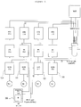
- FIG. 2a is a view showing the configuration of a system for simulating maintenance of a reactor core protection system of the present disclosure
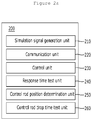
- FIG. 2b is a view showing the configuration of an apparatus for simulating maintenance of a reactor core protection system of the present disclosure.
- a nuclear power generator 400 including a reactor of the present disclosure may include at least two or more channels and preferably include a first channel 310, a second channel 320, a third channel 330 and a fourth channel 340.
- the first to fourth channels are connected to the nuclear power generator, receive state data generated by the nuclear power generator, and output a result signal.
- the channels may generate a trip signal to inform a user or a manger of the abnormal situation and shut down the nuclear power generator by dropping a control rod.
- the first to fourth channels are implemented using a computing device and output a result signal for the state signal generated by the nuclear power generator.
- a process signal input into the first to fourth channels is quadrupled 1, 2, 3 and 4 to input one signal into each of the four channels
- a control rod position signal may be duplicated RSPT1 and RSPT2.
- the first to fourth channels may include a core protection processor for executing a main algorithm of the reactor core protection system, such as calculation of DNBR, LPD or the like, a control rod assembly processor for collecting control rod assembly position signals and calculating a position signal deviation in each group or sub-group, a channel communication processor for collecting control rod position signals and transferring the control rod position signals to other channels, and transferring an overall signal including signals received from other channels to the control rod assembly processor, an interface test processor for transmitting various process variables received from other racks in a channel to the Qualified Indication and Alarm System - Non safety (QIAS-N), an operator module capable of monitoring major variables and changing set values, and a maintenance and test panel for performing periodic surveillance test and monitoring major variables.
- a core protection processor for executing a main algorithm of the reactor core protection system, such as calculation of DNBR, LPD or the like
- a control rod assembly processor for collecting control rod assembly position signals and calculating a position signal deviation in each group or sub-group
- a channel communication processor for collecting
- the channels are physically and electrically separated, and each of the channels independently derive its own result signal, and thus if two or more channels determine an abnormal situation, it is finally determined as an abnormal situation of the nuclear power generator.
- the first to fourth channels may confirm an abnormal situation by exchanging inputted control rod position signals with each other, and an abnormal situation determination unit of each channel may receive a control rod position signal and a state signal, confirm deviation of a state in each group, calculate a penalty factor based on the deviation, and transmit the penalty factor to all the channels through HR-SDL communication.
- the apparatus 200 for simulating maintenance of a reactor core protection system of the present disclosure is connected to the first to fourth channels during the maintenance period and operates to maintain the first to fourth channels connected to the nuclear power generator 400 to sense an abnormal situation of the reactor. Details of the configuration and technical content of the apparatus for simulating maintenance of a reactor core protection system will be described with reference to FIG. 2a .
- the apparatus 200 is for simulating maintenance of a reactor core protection system of the present disclosure, the reactor core protection system including at least two or more channels.
- the simulation apparatus 200 is an electronic control unit that in-eludes a central processing unit (CPU), read only memory (ROM), random access memory (RAM), and the like.
- the apparatus 200 executes various controls by loading programs stored in the ROM on the RAM and causing the CPU to execute the programs.
- the simulation apparatus 200 may be configured from a plurality of electronic control units.
- the simulation apparatus 200 may include a simulation signal generation unit 210, a communication unit 220, a control unit 230, a response time test unit 240, a control rod position determination unit 250 and a control rod drop time test unit 260.
- the simulation signal generation unit 210 may generate a simulation state signal including a normal state or an abnormal state. At this point, the simulation signal generation unit may generate a simulation state signal including at least any one of a reactor temperature, a reactor pressure, a hot leg temperature, a pump rotation speed, a neutron level, a flow rate and a reactor control rod position.
- the communication unit 220 is connected to each of the channels of the reactor core protection system and may transmit the simulation state signal to the channels. At this point, the communication unit may transmit the simulation state signal to all the first to fourth channels of the reactor core protection system. Unlike the conventional disclosure of connecting one simulation apparatus to only one channel, since the simulation apparatus of the present disclosure may transmit the simulation state signal to a plurality of channels, the simulation can be conducted without separate equipment.
- the simulation signal generation unit of the present disclosure may generate first to fourth simulation state signals for the reactor control rod position. Since a system for simulating maintenance of a reactor core protection system of the present disclosure may include first to fourth channels, the simulation signal generation unit of the present disclosure may individually generate a signal that can be input into each channel and input the signal into the channel.
- the communication unit may transmit the first simulation state signal to the first channel, the second simulation state signal to the second channel, the third simulation state signal to the third channel and the fourth simulation state signal to the fourth channel. Since the communication unit transmits the simulation state signal generated by the simulation signal generation unit to a relevant channel, the channel determines an abnormal situation by outputting a result signal for a corresponding simulation state signal.
- the first simulation state signal may include twenty-three signals
- the second simulation state signal may include seventy signals.
- the first to fourth simulation state signals correspond to a simulation state signal for a control rod position, and since a plurality of control rods may be included in one reactor of a nuclear power generator, the simulation signal generation unit generates ninety-three different simulation state signals, appropriately distributes the simulation state signals among the channels to be processed by each channel, and separately inputs twenty-three signals and seventy signals into each channel.
- the simulation signal generation unit of the present disclosure may generate a simulation state signal of a form including at least any one of a ramp signal, a step signal, an impulse signal, a pulse signal and a sinusoidal signal. Since a simulation can be properly conducted only when the simulation signal generation unit of the present disclosure generates a state signal of a form the same as that of a state signal generated by the nuclear power generator, the simulation signal generation unit is able to generate a state signal of all possible forms.
- the simulation signal generation unit of the present disclosure may generate a simulation signal of a form that can be generally used in a signal, such as a sinusoidal signal of a sinusoidal waveform of a trigonometric function, a ramp signal proportionally increasing after a predetermined time, a step signal outputting a constant value after a predetermined time, an impulse signal inputting an infinite value at a specific time, and a pulse signal.
- a simulation signal of a form that can be generally used in a signal, such as a sinusoidal signal of a sinusoidal waveform of a trigonometric function, a ramp signal proportionally increasing after a predetermined time, a step signal outputting a constant value after a predetermined time, an impulse signal inputting an infinite value at a specific time, and a pulse signal.
- the simulation signal generation unit of the present disclosure may simulate various forms of signals, including a hard wire signal and a communication signal, an unlimited number of times at a desired time, it may generate all forms of state signals generated by the nuclear power generator.
- the communication unit of the present disclosure may be connected to the reactor core protection system through a connector. Since the apparatus for simulating maintenance of a reactor core protection system of the present disclosure may generate all kinds of responses using only a simulator, it may progress a simulation by connecting a hard wire to the system through a connector without the need of separate equipment such as response time test equipment (RTTE) or resistors of the terminal block.
- RTTE response time test equipment
- the control unit 230 may receive a result signal output from the channel in response to the input simulation state signal and confirm whether the reactor core protection system normally determines a reactor core state by analyzing the result signal. Since the object of the apparatus for simulating a reactor core protection system of the present disclosure is to confirm whether the first to fourth channels properly operate, the control unit confirms whether an output signal corresponding to the input simulation state signal is properly output from each of the channels.
- a normal state output signal may be received from all of the channels.
- the control unit of the present disclosure may determine that the first channel is out of order and inform a manager or a maintenance technician of the corresponding content using an e-mail or a text message.
- control unit of the present disclosure may confirm whether the reactor core protection system suspends output of the trip signal. For example, if the simulation signal generation unit simulates twelve single control rod drops and a Reactor Power Cutback (RPC) request signal is output from the reactor core protection system, the control unit may confirm whether the reactor core protection system suspends the trip signal by subsequently inserting the control rod for reactor power cutback.
- RPC Reactor Power Cutback
- the response time test unit 240 may measure a time taken from transmission of the simulation state signal to reception of the result signal. Since the apparatus for simulating maintenance of a reactor core protection system of the present disclosure performs a function of confirming how fast a result signal is output in response to the simulation state signal input from each channel, the response time is measured through the response time test unit.
- the control unit may analyze corresponding content.
- the control unit of the present disclosure determines that the first to fourth channels operate normally.
- the control unit of the present disclosure confirms a channel of the delayed response time and determines that the third channel, which is the delayed channel, is out of order and informs a manager or a technical expert of corresponding content through an e-mail or a text message.
- FIG. 3 is a view showing the configuration of a simulation method of an apparatus for simulating maintenance of a reactor core protection system of the present disclosure.
- FIG. 3 this is an exemplary view showing a sequence of a simulation conducted by the apparatus for simulating maintenance of a reactor core protection system of the present disclosure.
- the simulation apparatus 200 may generate a simulation state signal that can be input into a first channel 310, a second channel 320, a third channel 330 and a fourth channel 340.
- the simulation state signal may include a first simulation state signal 211 for the position of a reactor control rod, a second simulation state signal 212 for the position of a reactor control rod, a third simulation state signal 213 for the position of a reactor control rod, and a fourth simulation state signal 214 for the position of a reactor control rod and may include a first simulation state signal 215, a second simulation state signal 216, a third simulation state signal 217 and a fourth simulation state signal 218 including general information such as a temperature, a pressure, a neutron level, a flow rate and the like.
- the simulation apparatus 200 may generate twenty-three of the first simulation state signal 211 for the position of a reactor control rod and transmit the first simulation state signals to the first channel 310 and may generate seventy of the second simulation state signal 212 for the position of a reactor control rod and transmit the second simulation state signals to the second channel 320.
- the first channel 310 may transmit twenty-three received first simulation state signals to the second channel 320
- the second channel 320 may transmit seventy received second simulation state signals to the first channel 310.
- communication between the first channel and the second channel may be accomplished through HR-SDL signals, and signal exchange can be conducted in a speedy way since communication between PCs is allowed.
- the first channel 310 and the second channel 320 analyze the first simulation state signal for the position of a reactor control rod and the second simulation state signal for the position of a reactor control rod received from each other and respectively generate a result signal. At this point, if the first simulation state signal for the position of a reactor control rod is determined as an abnormal state, each of the channels generates a trip signal 351 and 352 and transmits the trip signal to the simulation apparatus 200.
- the third channel 330 and the fourth channel 340 also determine a simulation state signal received from the simulation apparatus in a method the same as the signal exchange method of the first channel 310 and the second channel 320.
- a method of communicating between the channels includes a link method, a network method, a HR-SDL method, a HR-SDN method or the like, and communication between the channels may be accomplished in the various methods.
- the link or HR-SDL method performs peer-to-peer communication and may be used for an important data link for transmitting a control signal related to safety, such as a trip signal.
- a control signal related to safety such as a trip signal.
- a self-diagnosis, a variety of set values and constant values, a trip, a preliminary trip and the like may be transmitted to a processor, and whether or not the signals meet safety requirements may be determined.
- the network or HR-SDN method performs computer network communication and corresponds to one-to-many communication for controlling a plurality of apparatuses connected to a network by one central control apparatus.
- the apparatus for simulating maintenance of a reactor core protection system of the present disclosure may be used to train beginner operators or trainees of the reactor core protection system, in addition to conducting a maintenance simulation. Only experienced operators may operate the reactor core protection system, and verification on the channels may be performed using the simulation apparatus of the present disclosure before using the reactor core in order to perfectly guarantee a safety system of the reactor core.
- a beginner operator or a trainee, who operates the reactor core protection system for the first time, as well as an experienced operator may confirm how the reactor core protection system operates the safety system, and the simulation apparatus may be used as a training material for confirming the types of information collected from the reactor and the types of logic for shutting down the reactor.
- FIG. 4 is a view showing the configuration of measuring a control rod position drop response time of an apparatus for simulating maintenance of a reactor core protection system of the present disclosure
- FIG. 5 is a view showing a graph measuring a control rod position drop response time of an apparatus for simulating maintenance of a reactor core protection system.
- the apparatus for simulating maintenance of a reactor core protection system of the present disclosure may further include a control rod position determination unit 250 and a control rod drop time test unit 260.
- the control rod position determination unit 250 may receive a control rod position signal of the reactor core protection system, and the control rod drop time test unit 260 may measure a drop time of the control rod when the control rod of the reactor core protection system is shut down according to a simulation abnormal state signal generated by the simulation signal generation unit.
- the control rod position determination unit may configure a 1k ⁇ resistor, one hundred of 10 ⁇ resistors and a 1k ⁇ resistor in series and configure the resistors so that the total resistance may vary among the one hundred of 10 ⁇ resistors according to the movement of the control rod. Accordingly, since the total resistance value varies according to the position of the control rod, determination of the position of the control rod may be efficiently performed by adjusting the applied voltage out of the supply voltage of 15V to have a value between 5 and 10V.
- control rod drop time test unit may measure and store all of the drop time of the control rod for each of the channels.
- control unit may determine whether the reactor core protection system normally determines a reactor core state according to the measured drop time of the control rod.
- a control rod of a bar shape covered with a material easily absorbing thermal neutrons exists in the reactor core.
- reactivity of nuclear fuel is adjusted by inserting and withdrawing the control rod into and out of the reactor core, and if the control rod is inserted, reactivity of the reactor is lowered, and if the control rod is removed, reactivity of the reactor is increased. Accordingly, if an abnormal situation occurs in the reactor, the control rod is inserted for emergency shutdown of the reactor, and the reactor may be shut down by fully inserting the control rod.
- the apparatus for simulating maintenance of a reactor core protection system of the present disclosure may determine the current position of the control rod placed in the reactor core and measure performance of the reactor core protection system by measuring drop time of the control rod for fast shutdown of the reactor when an abnormal situation occurs in the reactor.
- a system for receiving a control rod position signal from a RSPT signal corresponds to the reactor core protection system, and the apparatus for simulating a reactor core protection system should receive information on the control rod position signal from the reactor core protection system to perform a control rod drop test.
- the internal structure of the reactor core protection system is a structure in which the CCP transfers total ninety-three pieces of information on the control rod position of RSPT1 and RSPT2 to the CEAP, and since the transmission port of the HR-SDL card of the controller is duplicated, the apparatus for simulating maintenance of a reactor core protection system may receive a signal the same as the control rod position signal transferred to the CEAP through an unused port.
- the apparatus for simulating maintenance of a reactor core protection system of the present disclosure applies a HR-SDL card for PC to directly receive the signal, records all the ninety-three RSPT1 signals and ninety-three RSPT2 signals every 50ms, and determines whether the control rod has dropped within the permitted range of time.
- the simulation apparatus artificially generates an abnormal state signal and inputs the signal into the PPS apparatus connected to two or more channels 1 and 2, and the apparatus for simulating maintenance of a reactor core protection system of the present disclosure generates a trip signal.
- the RTSS apparatus connected to the PPS apparatus transmits the trip signal to shut down the reactor by dropping the control rod in the reactor 3.
- a control rod position signal RSPT is transmitted to the first to fourth channels 310 to 340 4, and the first to fourth channels sense a corresponding control rod position signal and transmit values measuring the current position and the drop time of the control rod to the simulation apparatus 5.
- control rod of the reactor core protection system of the present disclosure when the control rod of the reactor core protection system of the present disclosure is shut down, a value measuring the drop time of the control rod can be confirmed.
- the control rod gradually drops as the control rod is shut down, and finally, the control rod is completely dropped to the bottom after about 5500ms.
- control rod position determination unit of the present disclosure may receive a control rod position signal from one of two channels among the first to fourth channels and receive a control rod position signal from one of two other channels. Since the first and second channels receive a control rod position signal and the third and fourth channels receive another control rod position signal, the control rod position determination unit of the present disclosure may receive two different control rod position signals.
- a system for simulating maintenance of a reactor core protection system of the present disclosure includes a simulation apparatus for generating a simulation state signal including a normal state or an abnormal state, and first to n-th channels included in the reactor core protection system and respectively connected to the simulation apparatus, in which the first to n-th channels receive the generated simulation state signal, output a result signal, and transmit the result signal to the simulation apparatus, and the simulation apparatus confirms whether the reactor core protection system normally determines a reactor core state by analyzing the result signal.
- FIG. 6 is a flowchart illustrating a method of simulating maintenance of a reactor core protection system of the present disclosure.
- a method of simulating maintenance of a reactor core protection system may include the steps of generating a simulation state signal including a normal state or an abnormal state, transmitting the simulation state signal to at least two or more channels respectively connected to the reactor core protection system, receiving a result signal output from each of the channels in response to the input simulation state signal, and confirming whether the reactor core protection system normally determines a reactor core state by analyzing the result signal.
- the system for simulating maintenance of a reactor core protection system of the present disclosure may perform an additional function for a configuration of inputting a simulation situation in the form of a power graph by a user or a manager and a behavior of the simulation apparatus conducted according to a virtual power input pattern.
- the control rod may be dropped or maintain its position according to a value of the power applied to the simulation system, and such a power value may be changed to an arbitrary value with respect to time. For example, it may be controlled to apply 5V between zero and one seconds, 10V between one and two seconds, and 0V between two and three seconds so that a simulation situation may be implemented using the system in each situation.
- the reactor of the present disclosure includes twelve control rods
- a simulation of shutting down the reactor when a few number of control rods are dropped may be configured through the simulation system.
- the apparatus for simulating maintenance of a reactor core protection system of the present disclosure may support input and output signals for all the four channels, as well as one channel, of the reactor core protection system, a rapid simulation can be conducted by reducing a response time between the input of a simulation state signal and the output of a result signal.
- the apparatus for simulating maintenance of a reactor core protection system of the present disclosure may simulate both a hard wire signal and a communication signal among input and output signals, two hundred or more different state signals of four channels may be input.
- the apparatus for simulating maintenance of a reactor core protection system of the present disclosure may conveniently progress a simulation since all simulations can be conducted only with the simulation apparatus without the need of an additional work of using response time test equipment (RTTE) or the like or inserting resistors in a terminal block.
- RTTE response time test equipment
- the apparatus for simulating maintenance of a reactor core protection system of the present disclosure may simulate various forms of signals (a ramp signal, a step signal and the like), including a hard wire signal or a communication signal, an unlimited number of times at a desired time.
- signals a ramp signal, a step signal and the like
- the apparatus for simulating maintenance of a reactor core protection system of the present disclosure may simulate various design basis accidents or various movements of a control rod may and conduct a variety of tests while all the channels are connected.
- the apparatus for simulating maintenance of a reactor core protection system of the present disclosure may reduce overall control rod drop test time and minimize the probability of malfunction at the site of a reactor by adding various test functions.
- the apparatus for simulating maintenance of a reactor core protection system of the present disclosure may greatly reduce the total test time including a time for setting a test environment and immediately display a control rod position signal received through measurement of a control rod drop time on a test screen.
- the apparatus for simulating maintenance of a reactor core protection system of the present disclosure may be used to construct a reactor core protection system by measuring a position and a drop speed of a control rod using a method of confirming a position of a control rod when a state of the reactor is confirmed.
Landscapes
- Engineering & Computer Science (AREA)
- Physics & Mathematics (AREA)
- General Engineering & Computer Science (AREA)
- High Energy & Nuclear Physics (AREA)
- Plasma & Fusion (AREA)
- Theoretical Computer Science (AREA)
- General Physics & Mathematics (AREA)
- Business, Economics & Management (AREA)
- Emergency Management (AREA)
- Computer Hardware Design (AREA)
- Automation & Control Theory (AREA)
- Mathematical Physics (AREA)
- Evolutionary Computation (AREA)
- Geometry (AREA)
- Monitoring And Testing Of Nuclear Reactors (AREA)
Claims (13)
- Générateur d'énergie nucléaire comprenant un système de protection de coeur de réacteur et ayant mis en oeuvre un appareil (200) pour simuler l'entretien du système de protection de coeur de réacteur, qui comprend au moins quatre canaux, CH, (310, 320, 330, 340), mis en oeuvre en utilisant des dispositifs de calcul,
l'appareil (200) comprenant :une unité de production de signal de simulation (210) configurée pour produire un signal d'état de simulation comprenant un état normal ou un état anormal et comprenant les premier au quatrième signaux d'état de simulation d'une position de tige de contrôle de réacteur,une unité de communication (220) connectée à chacun des canaux, CH, (310, 320, 330, 340) du système de protection de coeur de réacteur et configurée pour transmettre le signal d'état de simulation à chacun des canaux, CH, (310, 320, 330, 340) etle premier signal de simulation au premier canal (310),le deuxième signal de simulation au deuxième canal (320),le troisième signal de simulation au troisième canal (330) etle quatrième signal de simulation au quatrième canal (340), etune unité de contrôle (230) configurée pour recevoir une sortie de signal de résultat de chacun des canaux (310, 320, 330, 340) en réponse au signal d'état de simulation d'entrée, etpour confirmer si le système de protection de coeur de réacteur détermine normalement un état de coeur de réacteur en analysant le signal de résultat. - Générateur d'énergie nucléaire selon la revendication 1, dans lequel l'unité de production de signal de simulation (210) produit le signal d'état de simulation comprenant de plus au moins l'un quelconque d'une température de réacteur, d'une pression de réacteur, d'une température de jambe chaude, d'une vitesse de rotation de pompe, d'un niveau de neutrons, d'un débit.
- Générateur d'énergie nucléaire selon l'une quelconque des revendications 1 ou 2, dans lequel le premier signal de simulation comprend vingt-trois signaux et le deuxième signal de simulation comprend soixante-dix signaux.
- Générateur d'énergie nucléaire selon l'une quelconque des revendications précédentes, dans lequel l'unité de production de signal de simulation (210) est configurée pour produire un signal d'état de simulation d'une forme comprenant au moins un d'un signal de montée, d'un signal d'étape, d'un signal d'impulsion, d'un signal de pulsion et d'un signal sinusoïdal.
- Générateur d'énergie nucléaire selon l'une quelconque des revendications précédentes, dans lequel l'unité de communication (220) est connectée au système de protection de coeur de réacteur par un connecteur.
- Générateur d'énergie nucléaire selon l'une quelconque des revendications précédentes, comprenant en outre une unité de test de temps de réponse (240) configurée pour mesurer un temps pris de la transmission du signal d'état de simulation et de la réception d'un signal de résultat.
- Générateur d'énergie nucléaire selon la revendication 6, dans lequel l'unité de test de temps de réponse (240) est configurée pour mesurer le temps de réponse et l'unité de contrôle (230) est configurée pour analyser la teneur correspondante, si le temps de réponse est retardé plus longtemps qu'un temps de réponse standard prédéfini.
- Générateur d'énergie nucléaire selon l'une quelconque des revendications précédentes, comprenant en outre une unité de détermination de position de tige de contrôle (250) configurée pour recevoir le signal de position de tige de contrôle du système de protection de coeur de réacteur.
- Générateur d'énergie nucléaire selon l'une quelconque des revendications précédentes, comprenant en outre une unité de test de temps de chute de tige de contrôle (260) configurée pour mesurer un temps de chute d'une tige de contrôle quand la tige de contrôle du système de protection de coeur de réacteur est interrompue selon un signal d'état anormal de simulation produit par l'unité de production de signal de simulation (210).
- Générateur d'énergie nucléaire selon la revendication 9, dans lequel l'unité de test de temps de chute de tige de contrôle (250) est configurée pour mesurer et stocker l'ensemble des temps de chute de la tige de contrôle pour chacun des canaux (310, 320, 330, 340).
- Générateur d'énergie nucléaire selon la revendication 9 ou 10, dans lequel l'unité de contrôle (230) est configurée pour déterminer si le système de protection de coeur de réacteur détermine normalement un état de coeur de réacteur selon le temps de chute mesuré de la tige de contrôle.
- Générateur d'énergie nucléaire selon l'une des revendications 1 à 11, dans lequel le premier au quatrième canaux (310, 320, 330, 340) sont compris dans le système de protection de coeur de réacteur et respectivement connectés à l'appareil de simulation (200) .
- Procédé de simulation de l'entretien d'un système de protection de coeur nucléaire d'un générateur d'énergie nucléaire selon la revendication 1, le procédé comprenant les étapes de :production, en utilisant une unité de production de signal de simulation (210),d'un signal d'état de simulation comprenant un état normal ou un état anormal d'une position de tige de contrôle de réacteur,transmission, en utilisant une unité de communication (220),du signal d'état de simulation à chacun des canaux (310, 320, 330, 340) respectivement connectés au système de protection de coeur de réacteur etle premier signal d'état de simulation au premier canal (310),le deuxième signal d'état de simulation au deuxième canal (320),le troisième signal d'état de simulation au troisième canal (330) etle quatrième signal de transmission au quatrième canal (340) ;réception, en utilisant une unité de contrôle (230), d'une sortie de signal de résultat de chacun des canaux (310, 320, 330, 340) en réponse au signal d'état de simulation d'entrée ; etconfirmation, en utilisant l'unité de contrôle (230), si le système de protection de coeur de réacteur détermine normalement un état de coeur de réacteur en analysant le signal de résultat.
Applications Claiming Priority (1)
| Application Number | Priority Date | Filing Date | Title |
|---|---|---|---|
| KR1020160089982A KR101797078B1 (ko) | 2016-07-15 | 2016-07-15 | 원자로노심보호계통 유지보수 시뮬레이션 장치 및 시스템 |
Publications (2)
| Publication Number | Publication Date |
|---|---|
| EP3270382A1 EP3270382A1 (fr) | 2018-01-17 |
| EP3270382B1 true EP3270382B1 (fr) | 2019-07-03 |
Family
ID=58873659
Family Applications (1)
| Application Number | Title | Priority Date | Filing Date |
|---|---|---|---|
| EP17173391.8A Active EP3270382B1 (fr) | 2016-07-15 | 2017-05-30 | Appareil et système de simulation d'entretien d'un système de protection de noyau de réacteur |
Country Status (3)
| Country | Link |
|---|---|
| US (1) | US10580541B2 (fr) |
| EP (1) | EP3270382B1 (fr) |
| KR (1) | KR101797078B1 (fr) |
Cited By (1)
| Publication number | Priority date | Publication date | Assignee | Title |
|---|---|---|---|---|
| KR20200117212A (ko) * | 2019-04-03 | 2020-10-14 | 한국수력원자력 주식회사 | 노심보호계통 제어봉집합체프로세서의 동적 소프트웨어 검증시험 장치 및 방법 |
Families Citing this family (8)
| Publication number | Priority date | Publication date | Assignee | Title |
|---|---|---|---|---|
| US11398318B2 (en) * | 2017-06-02 | 2022-07-26 | Kepco Engineering & Construction Company, Inc. | Apparatus and method of evaluating response time of nuclear plant protection system |
| CN111008070B (zh) * | 2019-12-10 | 2023-05-12 | 北京科技大学 | 一种快中子反应堆全堆芯子通道并行任务划分方法及系统 |
| CN112562878A (zh) * | 2020-11-25 | 2021-03-26 | 三门核电有限公司 | 核电厂反应堆保护和监测系统响应时间测量装置及方法 |
| CN112668165B (zh) * | 2020-12-21 | 2022-06-17 | 中国核动力研究设计院 | 一种反应堆堆芯核设计系统及应用 |
| KR20230099903A (ko) | 2021-12-28 | 2023-07-05 | 주식회사 위존 | 위험작업 시뮬레이션 시스템 |
| KR102900361B1 (ko) * | 2023-05-09 | 2025-12-16 | 주식회사 수산이앤에스 | 제어봉 위치전송기 모의신호 발생 장치 |
| CN119673505B (zh) * | 2024-10-29 | 2025-07-18 | 中国核动力研究设计院 | 反应堆堆芯的在线保护方法、装置、介质及设备 |
| CN119864187B (zh) * | 2024-12-19 | 2025-11-14 | 中国核动力研究设计院 | 一种可变负载式棒位探测器模拟设备 |
Family Cites Families (10)
| Publication number | Priority date | Publication date | Assignee | Title |
|---|---|---|---|---|
| KR101473769B1 (ko) * | 2013-09-23 | 2014-12-17 | 두산중공업 주식회사 | 응답시간 측정 장치, 응답시간 측정 시스템 및 응답시간 측정 방법 |
| US4692299A (en) * | 1985-10-18 | 1987-09-08 | Westinghouse Electric Corp. | Testing sensor signal processors |
| US4783307A (en) * | 1987-03-05 | 1988-11-08 | Commonwealth Edison Company | Reactor control system verification |
| JP3514910B2 (ja) | 1996-05-24 | 2004-04-05 | 株式会社東芝 | 電動駆動型制御棒の健全性確認装置 |
| JP3892572B2 (ja) * | 1998-02-20 | 2007-03-14 | 株式会社東芝 | 制御棒操作監視制御システムの試験方法および試験装置 |
| KR20010037389A (ko) | 1999-10-16 | 2001-05-07 | 이호림 | 원자로의 부적절노심냉각감시기기에 대한 시험장치 및 방법 |
| US11017907B2 (en) * | 2013-12-31 | 2021-05-25 | Nuscale Power, Llc | Nuclear reactor protection systems and methods |
| JP2015145855A (ja) * | 2014-02-04 | 2015-08-13 | 株式会社東芝 | 原子炉の出力領域モニタの試験装置及びその試験方法 |
| KR101469175B1 (ko) * | 2014-07-28 | 2014-12-04 | 주식회사 포뉴텍 | 원자력 발전 보호계통 시뮬레이션 시스템 |
| KR20160089982A (ko) | 2015-01-21 | 2016-07-29 | 정세현 | 동작인식센서를 이용한 입력장치 |
-
2016
- 2016-07-15 KR KR1020160089982A patent/KR101797078B1/ko active Active
-
2017
- 2017-05-30 EP EP17173391.8A patent/EP3270382B1/fr active Active
- 2017-06-08 US US15/617,487 patent/US10580541B2/en active Active
Non-Patent Citations (1)
| Title |
|---|
| None * |
Cited By (1)
| Publication number | Priority date | Publication date | Assignee | Title |
|---|---|---|---|---|
| KR20200117212A (ko) * | 2019-04-03 | 2020-10-14 | 한국수력원자력 주식회사 | 노심보호계통 제어봉집합체프로세서의 동적 소프트웨어 검증시험 장치 및 방법 |
Also Published As
| Publication number | Publication date |
|---|---|
| EP3270382A1 (fr) | 2018-01-17 |
| KR101797078B1 (ko) | 2017-11-13 |
| US10580541B2 (en) | 2020-03-03 |
| US20180019029A1 (en) | 2018-01-18 |
Similar Documents
| Publication | Publication Date | Title |
|---|---|---|
| EP3270382B1 (fr) | Appareil et système de simulation d'entretien d'un système de protection de noyau de réacteur | |
| CN111665818B (zh) | 一种核电厂数字化仪控验证系统及其方法 | |
| KR101865666B1 (ko) | 원자로노심보호계통 소프트웨어 검증용 시뮬레이션 장치 및 시스템 | |
| CN103163398B (zh) | 核电站贝雷板件可靠性检测系统和方法 | |
| CN104809932B (zh) | 一种核电厂数字化安全级控制系统模拟装置 | |
| CN104898638B (zh) | 一种压水堆核电厂保护系统的定期试验装置 | |
| Rankin et al. | A hardware-in-the-loop simulation platform for the verification and validation of safety control systems | |
| CN104793075A (zh) | 一种压水堆核电厂保护系统的定期试验系统 | |
| CN113917901A (zh) | 一种核电厂全范围dcs模拟测试系统 | |
| CN116893624A (zh) | 一种生产线安全级控制系统运维仿真机及仿真方法 | |
| Nam et al. | HINT-Sec: Hardware-in-the-loop nuclear power plant testbed for cyber security | |
| CN115729217A (zh) | 一种晶闸管换流阀控制全链路的测试系统 | |
| Wu et al. | Development, verification and validation of an FPGA-based core heat removal protection system for a PWR | |
| CN117594260A (zh) | 一种核反应堆过程仪表模拟试验系统及方法 | |
| KR102228054B1 (ko) | 노심보호계통 제어봉집합체프로세서의 동적 소프트웨어 검증시험 장치 및 방법 | |
| RU2699688C1 (ru) | Тренажерный комплекс для подготовки эксплуатационного персонала Автоматизированных систем управления технологическим процессом (АСУ ТП) | |
| CN221175278U (zh) | 一种分散控制设备 | |
| KR20200117213A (ko) | 노심보호계통의 1채널 동적 시험장치 및 시험방법 | |
| CN110580566A (zh) | 一种仪控系统黑盒测试系统 | |
| Jervis | Models and simulation in nuclear power station design and operation | |
| Kropík et al. | New measuring and protection system at VR-1 training reactor | |
| Yatabe et al. | DEVELOPMENT OF A SEVERE ACCIDENT PROGRESSION SIMULATOR BASED ON THE MAAP CODE TO ASSIST IN ACCIDENT MANAGEMENT EDUCATION | |
| Végh et al. | Building up an on-line plant information system for the emergency response center of the hungarian nuclear safety directorate | |
| GOVINDARAJAN | MP SHARMA | |
| Zahedi | HARDWARE CONTROLLER IMPLEMENTATION OF CANDU NUCLEAR POWER PLANT SHUTDOWN SYSTEM |
Legal Events
| Date | Code | Title | Description |
|---|---|---|---|
| PUAI | Public reference made under article 153(3) epc to a published international application that has entered the european phase |
Free format text: ORIGINAL CODE: 0009012 |
|
| STAA | Information on the status of an ep patent application or granted ep patent |
Free format text: STATUS: REQUEST FOR EXAMINATION WAS MADE |
|
| 17P | Request for examination filed |
Effective date: 20170530 |
|
| AK | Designated contracting states |
Kind code of ref document: A1 Designated state(s): AL AT BE BG CH CY CZ DE DK EE ES FI FR GB GR HR HU IE IS IT LI LT LU LV MC MK MT NL NO PL PT RO RS SE SI SK SM TR |
|
| AX | Request for extension of the european patent |
Extension state: BA ME |
|
| RBV | Designated contracting states (corrected) |
Designated state(s): AL AT BE BG CH CY CZ DE DK EE ES FI FR GB GR HR HU IE IS IT LI LT LU LV MC MK MT NL NO PL PT RO RS SE SI SK SM TR |
|
| STAA | Information on the status of an ep patent application or granted ep patent |
Free format text: STATUS: EXAMINATION IS IN PROGRESS |
|
| 17Q | First examination report despatched |
Effective date: 20180622 |
|
| GRAP | Despatch of communication of intention to grant a patent |
Free format text: ORIGINAL CODE: EPIDOSNIGR1 |
|
| STAA | Information on the status of an ep patent application or granted ep patent |
Free format text: STATUS: GRANT OF PATENT IS INTENDED |
|
| INTG | Intention to grant announced |
Effective date: 20181214 |
|
| RAP1 | Party data changed (applicant data changed or rights of an application transferred) |
Owner name: DOOSAN HEAVY INDUSTRIES & CONSTRUCTION CO., LTD. |
|
| GRAJ | Information related to disapproval of communication of intention to grant by the applicant or resumption of examination proceedings by the epo deleted |
Free format text: ORIGINAL CODE: EPIDOSDIGR1 |
|
| STAA | Information on the status of an ep patent application or granted ep patent |
Free format text: STATUS: EXAMINATION IS IN PROGRESS |
|
| GRAR | Information related to intention to grant a patent recorded |
Free format text: ORIGINAL CODE: EPIDOSNIGR71 |
|
| GRAS | Grant fee paid |
Free format text: ORIGINAL CODE: EPIDOSNIGR3 |
|
| STAA | Information on the status of an ep patent application or granted ep patent |
Free format text: STATUS: GRANT OF PATENT IS INTENDED |
|
| INTC | Intention to grant announced (deleted) | ||
| GRAA | (expected) grant |
Free format text: ORIGINAL CODE: 0009210 |
|
| STAA | Information on the status of an ep patent application or granted ep patent |
Free format text: STATUS: THE PATENT HAS BEEN GRANTED |
|
| RAP1 | Party data changed (applicant data changed or rights of an application transferred) |
Owner name: DOOSAN HEAVY INDUSTRIES & CONSTRUCTION CO., LTD. |
|
| INTG | Intention to grant announced |
Effective date: 20190509 |
|
| AK | Designated contracting states |
Kind code of ref document: B1 Designated state(s): AL AT BE BG CH CY CZ DE DK EE ES FI FR GB GR HR HU IE IS IT LI LT LU LV MC MK MT NL NO PL PT RO RS SE SI SK SM TR |
|
| REG | Reference to a national code |
Ref country code: GB Ref legal event code: FG4D |
|
| REG | Reference to a national code |
Ref country code: CH Ref legal event code: EP Ref country code: AT Ref legal event code: REF Ref document number: 1151965 Country of ref document: AT Kind code of ref document: T Effective date: 20190715 |
|
| REG | Reference to a national code |
Ref country code: DE Ref legal event code: R096 Ref document number: 602017004955 Country of ref document: DE |
|
| REG | Reference to a national code |
Ref country code: IE Ref legal event code: FG4D |
|
| REG | Reference to a national code |
Ref country code: NL Ref legal event code: MP Effective date: 20190703 |
|
| REG | Reference to a national code |
Ref country code: LT Ref legal event code: MG4D |
|
| REG | Reference to a national code |
Ref country code: AT Ref legal event code: MK05 Ref document number: 1151965 Country of ref document: AT Kind code of ref document: T Effective date: 20190703 |
|
| PG25 | Lapsed in a contracting state [announced via postgrant information from national office to epo] |
Ref country code: NO Free format text: LAPSE BECAUSE OF FAILURE TO SUBMIT A TRANSLATION OF THE DESCRIPTION OR TO PAY THE FEE WITHIN THE PRESCRIBED TIME-LIMIT Effective date: 20191003 Ref country code: HR Free format text: LAPSE BECAUSE OF FAILURE TO SUBMIT A TRANSLATION OF THE DESCRIPTION OR TO PAY THE FEE WITHIN THE PRESCRIBED TIME-LIMIT Effective date: 20190703 Ref country code: SE Free format text: LAPSE BECAUSE OF FAILURE TO SUBMIT A TRANSLATION OF THE DESCRIPTION OR TO PAY THE FEE WITHIN THE PRESCRIBED TIME-LIMIT Effective date: 20190703 Ref country code: FI Free format text: LAPSE BECAUSE OF FAILURE TO SUBMIT A TRANSLATION OF THE DESCRIPTION OR TO PAY THE FEE WITHIN THE PRESCRIBED TIME-LIMIT Effective date: 20190703 Ref country code: LT Free format text: LAPSE BECAUSE OF FAILURE TO SUBMIT A TRANSLATION OF THE DESCRIPTION OR TO PAY THE FEE WITHIN THE PRESCRIBED TIME-LIMIT Effective date: 20190703 Ref country code: AT Free format text: LAPSE BECAUSE OF FAILURE TO SUBMIT A TRANSLATION OF THE DESCRIPTION OR TO PAY THE FEE WITHIN THE PRESCRIBED TIME-LIMIT Effective date: 20190703 Ref country code: BG Free format text: LAPSE BECAUSE OF FAILURE TO SUBMIT A TRANSLATION OF THE DESCRIPTION OR TO PAY THE FEE WITHIN THE PRESCRIBED TIME-LIMIT Effective date: 20191003 Ref country code: PT Free format text: LAPSE BECAUSE OF FAILURE TO SUBMIT A TRANSLATION OF THE DESCRIPTION OR TO PAY THE FEE WITHIN THE PRESCRIBED TIME-LIMIT Effective date: 20191104 Ref country code: NL Free format text: LAPSE BECAUSE OF FAILURE TO SUBMIT A TRANSLATION OF THE DESCRIPTION OR TO PAY THE FEE WITHIN THE PRESCRIBED TIME-LIMIT Effective date: 20190703 |
|
| PG25 | Lapsed in a contracting state [announced via postgrant information from national office to epo] |
Ref country code: AL Free format text: LAPSE BECAUSE OF FAILURE TO SUBMIT A TRANSLATION OF THE DESCRIPTION OR TO PAY THE FEE WITHIN THE PRESCRIBED TIME-LIMIT Effective date: 20190703 Ref country code: ES Free format text: LAPSE BECAUSE OF FAILURE TO SUBMIT A TRANSLATION OF THE DESCRIPTION OR TO PAY THE FEE WITHIN THE PRESCRIBED TIME-LIMIT Effective date: 20190703 Ref country code: LV Free format text: LAPSE BECAUSE OF FAILURE TO SUBMIT A TRANSLATION OF THE DESCRIPTION OR TO PAY THE FEE WITHIN THE PRESCRIBED TIME-LIMIT Effective date: 20190703 Ref country code: GR Free format text: LAPSE BECAUSE OF FAILURE TO SUBMIT A TRANSLATION OF THE DESCRIPTION OR TO PAY THE FEE WITHIN THE PRESCRIBED TIME-LIMIT Effective date: 20191004 Ref country code: RS Free format text: LAPSE BECAUSE OF FAILURE TO SUBMIT A TRANSLATION OF THE DESCRIPTION OR TO PAY THE FEE WITHIN THE PRESCRIBED TIME-LIMIT Effective date: 20190703 Ref country code: IS Free format text: LAPSE BECAUSE OF FAILURE TO SUBMIT A TRANSLATION OF THE DESCRIPTION OR TO PAY THE FEE WITHIN THE PRESCRIBED TIME-LIMIT Effective date: 20191103 |
|
| PG25 | Lapsed in a contracting state [announced via postgrant information from national office to epo] |
Ref country code: TR Free format text: LAPSE BECAUSE OF FAILURE TO SUBMIT A TRANSLATION OF THE DESCRIPTION OR TO PAY THE FEE WITHIN THE PRESCRIBED TIME-LIMIT Effective date: 20190703 |
|
| PG25 | Lapsed in a contracting state [announced via postgrant information from national office to epo] |
Ref country code: RO Free format text: LAPSE BECAUSE OF FAILURE TO SUBMIT A TRANSLATION OF THE DESCRIPTION OR TO PAY THE FEE WITHIN THE PRESCRIBED TIME-LIMIT Effective date: 20190703 Ref country code: EE Free format text: LAPSE BECAUSE OF FAILURE TO SUBMIT A TRANSLATION OF THE DESCRIPTION OR TO PAY THE FEE WITHIN THE PRESCRIBED TIME-LIMIT Effective date: 20190703 Ref country code: PL Free format text: LAPSE BECAUSE OF FAILURE TO SUBMIT A TRANSLATION OF THE DESCRIPTION OR TO PAY THE FEE WITHIN THE PRESCRIBED TIME-LIMIT Effective date: 20190703 Ref country code: IT Free format text: LAPSE BECAUSE OF FAILURE TO SUBMIT A TRANSLATION OF THE DESCRIPTION OR TO PAY THE FEE WITHIN THE PRESCRIBED TIME-LIMIT Effective date: 20190703 Ref country code: DK Free format text: LAPSE BECAUSE OF FAILURE TO SUBMIT A TRANSLATION OF THE DESCRIPTION OR TO PAY THE FEE WITHIN THE PRESCRIBED TIME-LIMIT Effective date: 20190703 |
|
| PG25 | Lapsed in a contracting state [announced via postgrant information from national office to epo] |
Ref country code: SM Free format text: LAPSE BECAUSE OF FAILURE TO SUBMIT A TRANSLATION OF THE DESCRIPTION OR TO PAY THE FEE WITHIN THE PRESCRIBED TIME-LIMIT Effective date: 20190703 Ref country code: IS Free format text: LAPSE BECAUSE OF FAILURE TO SUBMIT A TRANSLATION OF THE DESCRIPTION OR TO PAY THE FEE WITHIN THE PRESCRIBED TIME-LIMIT Effective date: 20200224 Ref country code: SK Free format text: LAPSE BECAUSE OF FAILURE TO SUBMIT A TRANSLATION OF THE DESCRIPTION OR TO PAY THE FEE WITHIN THE PRESCRIBED TIME-LIMIT Effective date: 20190703 |
|
| REG | Reference to a national code |
Ref country code: DE Ref legal event code: R097 Ref document number: 602017004955 Country of ref document: DE |
|
| PLBE | No opposition filed within time limit |
Free format text: ORIGINAL CODE: 0009261 |
|
| STAA | Information on the status of an ep patent application or granted ep patent |
Free format text: STATUS: NO OPPOSITION FILED WITHIN TIME LIMIT |
|
| PG2D | Information on lapse in contracting state deleted |
Ref country code: IS |
|
| 26N | No opposition filed |
Effective date: 20200603 |
|
| PG25 | Lapsed in a contracting state [announced via postgrant information from national office to epo] |
Ref country code: SI Free format text: LAPSE BECAUSE OF FAILURE TO SUBMIT A TRANSLATION OF THE DESCRIPTION OR TO PAY THE FEE WITHIN THE PRESCRIBED TIME-LIMIT Effective date: 20190703 |
|
| REG | Reference to a national code |
Ref country code: DE Ref legal event code: R119 Ref document number: 602017004955 Country of ref document: DE |
|
| PG25 | Lapsed in a contracting state [announced via postgrant information from national office to epo] |
Ref country code: MC Free format text: LAPSE BECAUSE OF FAILURE TO SUBMIT A TRANSLATION OF THE DESCRIPTION OR TO PAY THE FEE WITHIN THE PRESCRIBED TIME-LIMIT Effective date: 20190703 Ref country code: LI Free format text: LAPSE BECAUSE OF NON-PAYMENT OF DUE FEES Effective date: 20200531 Ref country code: CH Free format text: LAPSE BECAUSE OF NON-PAYMENT OF DUE FEES Effective date: 20200531 |
|
| REG | Reference to a national code |
Ref country code: BE Ref legal event code: MM Effective date: 20200531 |
|
| PG25 | Lapsed in a contracting state [announced via postgrant information from national office to epo] |
Ref country code: LU Free format text: LAPSE BECAUSE OF NON-PAYMENT OF DUE FEES Effective date: 20200530 |
|
| PG25 | Lapsed in a contracting state [announced via postgrant information from national office to epo] |
Ref country code: IE Free format text: LAPSE BECAUSE OF NON-PAYMENT OF DUE FEES Effective date: 20200530 Ref country code: FR Free format text: LAPSE BECAUSE OF NON-PAYMENT OF DUE FEES Effective date: 20200531 |
|
| PG25 | Lapsed in a contracting state [announced via postgrant information from national office to epo] |
Ref country code: BE Free format text: LAPSE BECAUSE OF NON-PAYMENT OF DUE FEES Effective date: 20200531 Ref country code: DE Free format text: LAPSE BECAUSE OF NON-PAYMENT OF DUE FEES Effective date: 20201201 |
|
| PG25 | Lapsed in a contracting state [announced via postgrant information from national office to epo] |
Ref country code: MT Free format text: LAPSE BECAUSE OF FAILURE TO SUBMIT A TRANSLATION OF THE DESCRIPTION OR TO PAY THE FEE WITHIN THE PRESCRIBED TIME-LIMIT Effective date: 20190703 Ref country code: CY Free format text: LAPSE BECAUSE OF FAILURE TO SUBMIT A TRANSLATION OF THE DESCRIPTION OR TO PAY THE FEE WITHIN THE PRESCRIBED TIME-LIMIT Effective date: 20190703 |
|
| PG25 | Lapsed in a contracting state [announced via postgrant information from national office to epo] |
Ref country code: MK Free format text: LAPSE BECAUSE OF FAILURE TO SUBMIT A TRANSLATION OF THE DESCRIPTION OR TO PAY THE FEE WITHIN THE PRESCRIBED TIME-LIMIT Effective date: 20190703 |
|
| PGFP | Annual fee paid to national office [announced via postgrant information from national office to epo] |
Ref country code: CZ Payment date: 20250521 Year of fee payment: 9 |
|
| PGFP | Annual fee paid to national office [announced via postgrant information from national office to epo] |
Ref country code: GB Payment date: 20260313 Year of fee payment: 10 |