EP3270401A1 - Commutateur thermique dote de vitre isolante - Google Patents
Commutateur thermique dote de vitre isolante Download PDFInfo
- Publication number
- EP3270401A1 EP3270401A1 EP16178866.6A EP16178866A EP3270401A1 EP 3270401 A1 EP3270401 A1 EP 3270401A1 EP 16178866 A EP16178866 A EP 16178866A EP 3270401 A1 EP3270401 A1 EP 3270401A1
- Authority
- EP
- European Patent Office
- Prior art keywords
- switch
- cover part
- switch according
- contact surface
- curved edge
- Prior art date
- Legal status (The legal status is an assumption and is not a legal conclusion. Google has not performed a legal analysis and makes no representation as to the accuracy of the status listed.)
- Granted
Links
Images


Classifications
-
- H—ELECTRICITY
- H01—ELECTRIC ELEMENTS
- H01H—ELECTRIC SWITCHES; RELAYS; SELECTORS; EMERGENCY PROTECTIVE DEVICES
- H01H37/00—Thermally-actuated switches
- H01H37/02—Details
- H01H37/32—Thermally-sensitive members
- H01H37/52—Thermally-sensitive members actuated due to deflection of bimetallic element
- H01H37/54—Thermally-sensitive members actuated due to deflection of bimetallic element wherein the bimetallic element is inherently snap acting
- H01H37/5427—Thermally-sensitive members actuated due to deflection of bimetallic element wherein the bimetallic element is inherently snap acting encapsulated in sealed miniaturised housing
-
- H—ELECTRICITY
- H01—ELECTRIC ELEMENTS
- H01H—ELECTRIC SWITCHES; RELAYS; SELECTORS; EMERGENCY PROTECTIVE DEVICES
- H01H37/00—Thermally-actuated switches
- H01H37/02—Details
- H01H37/04—Bases; Housings; Mountings
- H01H2037/046—Bases; Housings; Mountings being soldered on the printed circuit to be protected
Definitions
- the present invention relates to a temperature-dependent switch having a housing which comprises a cover part with an upper side and a lower part with a peripheral wall, the upper portion of which engages over the cover part, with at least one arranged on the top of the cover part first outer contact surface, at least one on the outside the housing provided second outer contact surface, and at least one arranged at least on the upper side of the cover part protective film, wherein the cover part cross-upper portion of the peripheral wall of the lower part holds the lid part with the interposition of the protective film on the lower part, and arranged with a temperature-dependent in the housing Derailleur, which establishes or opens in dependence on its temperature, an electrically conductive connection between the first and the second outer contact surface.
- Such a switch is from the DE 196 23 570 A1 known.
- the known temperature-dependent switch is used in a conventional manner to monitor the temperature of a device. For this purpose, for example, it is brought into thermal contact with the device to be protected via one of its outer surfaces, so that the temperature of the device to be protected influences the temperature of the derailleur.
- the switch is electrically connected via the soldered to its two outer contact pads leads in series in the supply circuit of the device to be protected, so that below the response temperature of the switch, the supply current of the device to be protected flows through the switch.
- the known switch has a deep-drawn lower part, in which an inner circumferential shoulder is provided, on which a lid part rests.
- the lid part is held firmly on this shoulder by a raised and at its upper portion by about 60 ° inwardly bent circumferential wall of the base.
- cover part and lower part are made of electrically conductive material, an insulating film extending around the cover part is provided between them, which extends inwardly in the switch parallel to the cover part and is pulled up laterally, so that its edge region except for the Extends the top of the lid part.
- the bent upper portion of the peripheral wall of the lower part rests on the edge region of the insulating film, wherein the wall and edge region of the insulating film at an angle of approximately 30 ° to the top of the cover part of this pioneering.
- the end face of the upper portion of the peripheral wall thus has an angle of 90 ° to the insulating film.
- the temperature-dependent switching mechanism here comprises a spring snap-action disk, which carries the movable contact part, as well as a bimetallic disk which is put over the movable contact part.
- the spring snap-action disc presses the movable contact part against a stationary counter contact on the inside of the cover part.
- the spring snap-action disc With its edge, the spring snap-action disc is supported in the lower part of the housing, so that the electric current flows from the lower part through the spring snap-action disc and the movable contact part into the stationary counter-contact and from there into the cover part.
- first outer terminal is a first outer contact surface, which is arranged centrally on the cover part.
- second outer terminal provided on the flanged edge of the lower part second outer contact surface is used. But it is also possible to arrange the second external connection not on the edge but laterally on the current-carrying housing or on the underside of the lower part.
- This design is particularly chosen when very high currents must be switched, which can not be easily passed through the spring washer itself.
- a bimetal disc is provided for the temperature-dependent switching function, which rests below its critical temperature without force in the switching mechanism, wherein it is arranged geometrically between the contact part or the contact bridge and the spring snap-action disc.
- a multi-layer active sheet-metal components made of two, three or four are inseparably connected to one another Components with different coefficients of expansion understood.
- the connection of the individual layers of metals or metal alloys are cohesively or positively and are achieved for example by rolling.
- bimetallic parts In their low-temperature position, such bimetallic parts have a first and their high-temperature position have a second stable geometric conformation, between which they change over in a temperature-dependent manner in the manner of a hysteresis. When the temperature changes beyond its response temperature or below its return temperature, the bimetal parts snap over into the other conformation.
- the bimetal parts are therefore often referred to as snap disks, wherein they can have an elongated, oval or circular shape in plan view.
- the bimetallic disc changes its configuration and works against the spring snap-action disc, that they are the movable contact part of the stationary mating contact and the current transfer member of the two stationary mating contacts lifts, so that the switch opens and the device to be protected is turned off and can not heat up.
- the bimetallic disc is mounted mechanically free of forces below its transition temperature, wherein the bimetallic disc is not used to guide the flow.
- bimetallic discs have a long mechanical life, and that the switching point, so the critical temperature of the bimetal disc, not changed even after many switching cycles.
- the bimetallic snap disk can also take over the function of the spring snap-action disc and possibly even the current transfer member, so that the switching mechanism comprises only one bimetallic disc, which then the carries movable contact part or instead of the current transmitting member has two contact surfaces, so that the bimetallic disc not only provides for the closing pressure of the switch, but also leads the current in the closed state of the switch.
- temperature-dependent switch which have no contact plate as a current transfer member but a spring member which carries the two mating contact or on which the two mating contacts are formed.
- the spring member may be a Bimetallteil, in particular a bimetallic snap disk, which not only provides the temperature-dependent switching function, but at the same time also provides the contact pressure and the current leads when the switch is closed.
- the bimetallic disc can take over the function of the spring snap-action disc.
- the PTC thermistor cover is electrically connected in parallel to the two outer terminals, so that it gives the switch a self-holding function.
- PTC thermistors are also referred to as PTC resistors. They are made, for example, from semiconductive, polycrystalline ceramics such as BafiO 3 .
- the cover part made of PTC thermistor material, so that it also has a self-holding function.
- the outer heads form the two outer terminals, and interact their inner heads as a stationary mating contacts with the contact bridge.
- the cover member may be made of insulating material or metal in a switch of this type also, in the latter case as from the DE 196 23 570 A1 Known switch is provided around the cover part extending around insulating sheet, which extends inside the switch in parallel to the cover part and is pulled up laterally, so that its edge region extends to the top of the cover part.
- the radially inwardly bent by about 60 ° upper portion of the peripheral wall of the base presses while laying the insulating film flat on the lid part.
- the housing is typically protected from the entry of contaminants by a seal which is applied before or even after the connection of terminal lugs or connecting leads to the external terminals.
- the cover part provided with a bead, with which it penetrates when bending the upper portion of the peripheral wall of the lower part in the insulating film. Although this ensures a better seal, in many cases, however, penetrates paint into the interior of the housing.
- the DE 10 2013 102 089 B4 describes a switch, as in principle from the above-mentioned DE 196 23 570 A1 is known.
- This switch has between the shoulder in the lower part and the cover part on a spacer ring, which allows a larger switching distance between the movable contact part and stationary counter contact.
- the edge region of the insulating is cut from the outside V-shaped, whereby the ripple is greatly reduced, so that the tightness is improved.
- the DE 10 2013 102 006 B4 also describes a switch, as in principle from the above-mentioned DE 196 23 570 A1 is known.
- This switch is like the one from the DE 195 17 310 A1 Known switch on a cover part of PTC thermistor material. Because of the lack of pressure stability of this PTC cover, can be effected by the approximately 90 ° radially inwardly bent upper portion of the peripheral wall of the base no adequate sealing of the known switch against the entry of impurities, which is why the bent upper portion of the peripheral wall at the time of the DE 195 17 310 A1 known switch must be sealed against the top of the lid part with silicone, which often causes problems.
- the DE 10 2013 102 006 B4 solves this problem in that a cover sheet is provided, which rests only on the top of the PTC lid, and in which the bent by about 90 ° and flat on the cover flying up the upper portion of the peripheral wall of the base penetrates.
- the end face of the upper portion of the peripheral wall faces away from the cover sheet.
- the flat-lying upper portion of the peripheral wall of the base often does not provide the desired seal.
- both a flat-lying cover sheet, as they are known from DE 10 2013 102 006 B4 is known, as well as the edge region of an example of the DE196 23 579 A1 or the DE 10 2013 102 089 B4 known, extending around the lid part around insulating film which extends inside the switch between the lower part and the lid part and is pulled laterally between the wall of the lower part and the lid part and turned over with its edge region on top of the lid part.
- a protective film in the sense of the present invention can serve for the electrical insulation, the mechanical protection and / or the sealing of the interior of the switch.
- an insulating covering film for example made of Nomex®, which extends with its edge radially outwards up to the insulating film, which consists for example of Kapton®.
- Nomex® and Kapton® consist of aramid paper or aromatic polyimides.
- the present invention seeks to eliminate in the known switch in a structurally simple and inexpensive way, the above-mentioned problems, at least reduce.
- the lid portion overlapping upper portion of the peripheral wall of the lower part is formed as a continuous curved edge, which preferably presses with its end face on the protective film.
- the upper portion of the peripheral wall is therefore not bent radially inwardly as in the prior art, but bent in itself so that it forms a continuous curved edge in the manner of a bead, where it can get into contact with the protective film with its end face on which it preferably rests sealingly.
- the protective film is an insulating film extending around the lid part, its edge region is pushed further towards the upper side of the lid part as the upper portion of the peripheral wall is further bent, thereby already providing better sealing of the switch.
- the front side can also penetrate into the edge region, which further improves the seal, because a self-contained connection between arched edge and insulating film is formed.
- the protective film is a covering film resting on the upper side of the cover part, then the end face of the curved edge penetrates into the covering film, which here too improves the sealing because a self-contained connection arises between the curved edge and cover film
- the front side of the upper portion is bent inwardly by at least 90 °, so that a circumferential bead is formed, which is for example U-shaped in cross section, when the portion is bent or curved in itself by about 180 °.
- a circumferential bead is formed, which is for example U-shaped in cross section, when the portion is bent or curved in itself by about 180 °.
- the protective film is an insulating film running around the lid part, whose edge region extends at an angle to the top side of the lid part, an additional sealing of the interior of the switch results, which provides an overall better seal.
- the inventor of the present application has recognized that the problems with the tightness of the known switches are due to the fact that the insulating sheet curls or wrinkles when bent on the top of the lid member, resulting in that the wall of the base is not far enough on the top of the lid part can be bent. Furthermore, this waviness of the insulating foil on the upper side and on the peripheral end side of the lid part causes creepage paths for liquids to form, so that when impregnating the known switch with protective lacquers they can creep into the interior of the switch.
- the bent edge of the lower part does not seal the upper side so well that in any case it is ensured that no liquid can get into the interior of the switch during resin formation.
- SMD Surface Mounted Device
- Reel belt and coil
- Pick and Place SMD placement machines on a printed circuit board apply and mount there and eg to contact in the reflow process.
- both the curved edge and the one or both contact surfaces on the top of the cover part can be used as a contact surface for the Surface Mounted Technology (SMT) compound.
- SMT Surface Mounted Technology
- the switch with the cover part is placed on the printed circuit board, so that the contact surface or the contact surfaces on the upper side of the cover part and the curved edge are available for SMT contacting.
- the edge serves the mechanical fixing and the thermal connection of the switch to the circuit board and the electrical contact, if only one contact surface on the top of the cover part is present.
- the curved edge defines a first plane which defines at least one contact surface on the upper side, a second plane parallel to the first plane, and the first and the second plane are at a distance from one another, which is an assembly of the switch on a circuit board with SMT allows, preferably less than 2 mm.
- the inventors of the present application have recognized that bending the upper portion of the circumferential wall forms a curved edge which spans a plane approximately at the same level as the plane passing through the one or more contact surfaces the top of the ceiling part is clamped. These two levels are spaced so close together that the top of the switch can first be mounted on a Surface Mounted Technology (SMT) circuit board.
- SMT Surface Mounted Technology
- the distance between the two planes is less than 2 mm, in a preferred embodiment even less than 1 mm, these differences in height can be easily compensated by the solder paste in SMT.
- the at least one protective film comprises an insulating film, which extends inside the switch between the lower part and the lid part and laterally between the peripheral wall of the lower part and the lid part and is folded over with its edge region on the upper side of the lid part.
- the new switch can be formed with electrically conductive lower part and electrically conductive cover part, wherein the insulating film for electrical insulation between the cover part and lower part is used and at the same time prevents the ingress of contaminants into the interior of the switch.
- the arched edge according to the invention results in an additional sealing of the switch, namely because the curved edge presses with its end face the insulating film on the top of the cover part and possibly even penetrates into this, so that the curved edge an annular protection against the ingress of contaminants represents.
- the insulating film may have compared to the insulating films used in the prior art have a smaller outer diameter, whereby the waves and wrinkles are reduced, which arise when turning over the insulating film.
- This smaller diameter insulating film can be used because a particularly good seal of the new switch is realized by the curved edge, so that less material of an insulating film is required for the seal.
- this insulating film can also be used when the cover part and / or lower part are not made of electrically conductive material, so that the insulating film is only the mechanical seal against the entry of impurities, but not the electrical insulation.
- the at least one protective film comprises a cover film which rests on the upper side of the cover part, the cover film preferably extending to below the edge region of the insulating film.
- the cover film When the cover film is used alone, it is used in switches in which usually the upper part is not made of metal, but consists of electrically insulating plastic or PTC material.
- the cover then serves both the mechanical protection of the upper part, on the other hand, the seal between the curved edge and the top of the cover part.
- the front side of the curved edge can also be bent down so far on the cover that it penetrates into the cover, which also causes a particularly efficient over the entire circumference of the curved edge.
- the cover film is used in addition to the insulating film, this ensures a particularly good sealing of the new switch, wherein the diameter of the insulating film may be chosen so that the end face of the curved edge either penetrates into the resting on the cover film edge region of the insulating film, or but in the cover itself, namely because the insulating ends with its edge region under the curved edge of the peripheral wall.
- the protective film consists of polyimide, preferably of aromatic polyimide, or aramid paper.
- Such protective films are known from the prior art, they are sold, for example under the trade name Kapton® or Nomex®.
- Insulating films made of these materials are characterized by the fact that they are "drawable”, so slightly stretch when inserting the lid part in the lower part, and that they can still be folded well around the front side of the lid part on the top, and further the required Dielectric strength is achieved.
- the switching mechanism carries a movable contact part, which cooperates with a stationary counter-contact, which on an inner side the lid part is arranged and cooperates with a arranged on the top first outer contact surface.
- the two outer contact surfaces are almost in one plane, so that the switch can be mounted with the lid part on a printed circuit board according to SMT and contacted.
- the curved edge serves not only the mechanical fixation and the electrical contact of the switch, but at the same time the thermal connection to the circuit board, further being given a further protection against the ingress of contaminants, because the curved edge closes the top of the lid part tight towards the outside.
- the second outer contact surface is arranged on the upper side of the cover part, wherein preferably the switching mechanism then carries a Stromübertragungsglied, which cooperates with two stationary mating contacts, which are arranged on an inner side of the cover part, and one of which with a the two arranged on the top outer contact surfaces cooperates.
- the new switch can also be designed for switching and carrying very high currents, what the two stationary mating contacts interact with a current transfer member in the form of a contact bridge or a contact plate, so that the operating current of the device to be protected not by the spring -Schnappulation or even the bimetallic snap disk but only flows through the power transmission element.
- the curved edge then serves not the electrical contact, but on the one hand, the mechanical fixation and the thermal connection, on the other hand, the protection of the top of the lid part before the entry of impurities.
- the curved edge surrounds after mounting on the circuit board, the contact surface or the contact surfaces on the top of the cover part and the transition between the protective film on the top of the lid part and the front side of the curved edge, so is a barrier against the ingress of contaminants.
- the cover part and / or the lower part can be made of electrically conductive material, which allows the construction of a mechanically very pressure-resistant and easy to manufacture switch.
- the switching mechanism has a bimetal part.
- the bimetallic part may be a round, preferably circular bimetal snap-action disc, wherein it is also possible to use as bimetallic an elongated, cantilevered bimetallic spring. With simple switches, this bimetal can also be used to conduct electricity.
- the rear derailleur additionally has a spring snap-action disc.
- This spring snap-action disc can, for example, carry the movable contact part and carry the current through the closed switch and, in the closed state, provide for the contact pressure. In this way, the bimetal is relieved of both the current flow and the mechanical load when it is closed.
- the derailleur has a current transmitting member which cooperates with two stationary mating contacts, either only one bimetallic part can be provided, which then provides the closing pressure and the opening function takes over, or it can additionally be provided a spring member, which expends the closing force, so that the bimetal part is only mechanically loaded when it opens the switch.
- the present invention is particularly suitable for round temperature-dependent switches, which are thus round, circular or oval in the plan view of the lower part or cover part, with other housing forms can use the invention, when bending over the upper portion of the peripheral wall of the lower part of the curved Edge arises, which presses on the protective film and thus exerts the protective function against the entry of impurities.
- the present invention also relates to an electronic circuit with at least one mounted on a circuit board, temperature-dependent switch according to the invention, wherein the switch rests with its cover part on the circuit board.
- the new temperature-dependent switch can be used as an SMD component, without additional contact lugs, contact bridges or connecting leads are required to electrically connect the switch to the printed circuit board.
- the curved edge not only serves the electrical contact, but also serves in the sense already described above as a barrier against the entry of impurities. Even if the end of the curved edge does not press on the protective film or even penetrates into this, it is very effectively ensured at least in a ready-mounted switch that no contaminants from the top of the switch can get into the interior of the switch, Namely, because the top of the switch is effectively protected from the entry of particulate or liquid contaminants by the soldering edge acting as a barrier.
- the second outer contact surface is arranged on the curved edge, wherein alternatively the second outer contact surface can also be arranged on the upper side of the cover part and is soldered to a third soldering surface provided on the printed circuit board.
- the curved edge can serve for the mechanical fixation and for the formation of a barrier against contamination, while at the same time serving as a second contact surface.
- a vent hole is provided, which opens into a space which is formed between the circuit board and the curved edge.
- Fig. 1 is shown schematically, not to scale and in the lateral section a circular in plan view temperature-dependent switch 10 ', as is known from the prior art.
- the well-known switch 10 has a temperature-dependent switching mechanism 11, which is arranged in a housing 12 in which an insulating film 13 is arranged between a cup-shaped lower part 14 and a lid part 15 extends, which closes the lower part 14.
- a circumferential, stepped shoulder 16 is provided, on which a spacer ring 17 is arranged, on which the lid part 15 rests under intermediate storage of the insulating film 13, the edge region 18 extends to the top of the lid part 15.
- the lower part 14 has a circumferential wall 19, whose upper portion 20 engages over the lid part 15.
- the upper portion 20 is bent radially inwardly so that it presses the lid member 15 on the spacer ring 17 and this on the peripheral shoulder 16.
- Lower part 14 and cover part 15 are made of electrically conductive material in the embodiment shown, which is why the cover 15 is provided around extending insulating film 13 which extends inside the housing 12 parallel to the cover member 15, laterally between the wall 19 and the cover part 15 is guided upward and with its edge region 18 facing upward.
- the upper portion 20 of the wall 19 lies flat on the edge region 18 of the insulating film 13, and pushes it toward the top 21 of the cover part 14.
- the at its edge region 18 thereby radially inwardly folded, rigid insulating film 13 is thereby in its edge region 18th wavy and forms wrinkles, whereby it exerts a back pressure on the upper portion 20, so that edge region 18 and upper portion 18 extend to the top 21 at an angle W, which is about 30 °.
- edge portion 18 is above over the upper portion 20 via.
- a further insulating cover 22 is provided, which extends radially outwards to the edge region 18 of the insulating film 13.
- the folds of the edge region 18 can not be reliably sealed in every manufacturing process, so that it is ensured in each case that no contaminants can enter the interior of the switch 10 in the region of the angle W.
- the housing 12 is therefore usually protected against the entry of impurities by an additional seal, wherein it can not be ruled out that the coating enamel used in this case penetrates into the housing 12.
- a stationary mating contact 24 is arranged, with which a movable contact part 25 supported by the switching mechanism 11 cooperates.
- the rear derailleur 11 comprises a spring snap-action disc 26, which is permanently clamped with its edge 27 between the spacer ring 17 and the shoulder 16, so that it produces a permanent electrically conductive connection there.
- a bimetal snap-action disc 28 is provided below the spring snap-action disc 26, that is on its side facing away from the stationary counter-contact 24 side, which has two geometric temperature positions, the in Fig. 1 shown low-temperature position and a high-temperature position, not shown.
- the bimetallic snap disk 28 lies with its edge 29 freely above a wedge-shaped, circumferential shoulder 31, which is formed on an inner bottom 32 of the lower part 14.
- the lower part 14 has an outer bottom 33, is made with the thermal contact with a device to be protected.
- the bimetallic snap disk 28 is supported on a peripheral shoulder 34 of the contact part 25 with its center 35.
- the spring snap-action disc 26 is connected to an inner region 36 in its center permanently connected to the movable contact part 25, to which on the pin 30 which projects through the two snap discs 26 and 28, a ring 37 is pressed, on which also the shoulder 34 is formed.
- the electrically conductive connected to the top 21 of the cover member 15 stationary counter-contact 24 cooperates with the movable contact part 25 and via this with the inner portion 36 of the spring snap-action disc 26, the mechanically and electrically permanently with the shoulder 16 and via this with the lower part 14 is connected.
- the top 21 serves as the first outer contact surface 38, which is indicated by a black area.
- the outer bottom 33 of the lower part 14 is used in the known switch as a further contact surface, wherein it is also known to use as the second outer contact surface 39, the upper portion 20 of the wall 19.
- the bimetallic snap disk 28 presses with its center 35 on the shoulder 34 and thus lifts the movable contact part 25 from the stationary counter contact 24.
- the spring snap-action disc 26 may be a bistable spring washer, which is geometrically stable even in the open position of the switch, so that the movable contact member 25 does not come back into contact with the stationary counter contact 24 even if the edge 29 of the bimetallic snap disk 28 no longer presses against the edge 27 of the spring snap-action disc 26.
- the temperature inside the switch 10 is lowered again, then moves the edge 29 of the bimetallic snap disk 26 down and comes into abutment with the wedge-shaped shoulder 31. With its center 35, the bimetallic snap disk 26 then presses from below against the spring snap-action disc 26 and pushes them back into their other geometrically stable position, in accordance with Fig. 1 the movable contact member 25 presses against the stationary mating contact 24.
- the rear derailleur 11 in addition to the bimetallic washer 28, the current-spring spring snap-action disc 26, wherein in the rear derailleur 11, only the bimetallic snap disk 28 may be provided, which would then be clamped with its edge 29 under the rotating ring 17 and would lead the stream.
- Fig. 2 is the development of the switch 10 'according to the invention Fig. 1 shown, wherein the new switch 10 is cut only cut in the upper section.
- the upper portion 20 of the peripheral wall 19 is at the switch 10 from Fig. 2 bent inwardly so that a continuously curved edge 41 is formed, which rests with its end face 42 on the edge region 18 of the insulating film 13.
- the end face 42 is so in contact with the edge region 18 arrives that this is pressed to the top of the cover member 15, so it applies more tightly to the cover 22, as this at the switch off Fig. 1 the case is.
- the upper portion 20 in the embodiment of Fig. 2 bent over almost 180 °, so that the curved edge 41 in cross section looks like a U-shaped bead.
- the edge region 18 of the insulating film 13 can also be turned over only slightly on the upper side of the cover part 15 so that it ends within the U-shaped bead of the edge 41 so that the end face 42 comes into contact with the cover film 22 past the edge region 18 ,
- the switch points according to Fig. 2 a further advantage, which is additionally or independently of the sealing effect of the curved edge 41 can be realized.
- the curved edge 41 spans a plane 43 which lies parallel to a plane 44 which spans the first contact surface 38 on the upper side of the cover part 15.
- the indicated at 45 distance between the two planes 43 and 44 is so small that it can be compensated by the solder paste in SMT assembly.
- the distance 45 is less than 0.3 mm.
- the switch 10 depending on the design has a diameter between 8 and 20 mm and has a height of 6 to 15 mm.
- Fig. 3 is the assembly of the switch 10 off Fig. 3 shown on a printed circuit board 46, to which the switch 10 is placed with its lid part 15 on the circuit board 46.
- annular soldering surface 47 is provided, which corresponds to the diameter of the curved edge 41. Within the annular soldering surface 47, a soldering surface 48 is centrally provided, which serves to contact the first contact surface 38.
- a vent hole 49 is provided in the printed circuit board 46.
- solder pastes 51, 52 are applied on the annular soldering surface 47 and on the central soldering surface 48, whereupon the switch is thus placed upside down on the printed circuit board 46, so to speak, that the soldering paste 51 between the annular soldering surface 47 and the curved edge 41 and the solder paste 52 between the central soldering surface 48 and the first outer contact surface 38th
- solder pads 47, 48 and the outer contact surfaces 38, 39 are now soldered together.
- a space 53 is formed between the printed circuit board 46 and the curved edge 41, which is vented through the vent hole, so that no mechanical disturbing forces occur during soldering.
- the curved edge 41 thus ensures SMD mounting of the switch 10 for a protection of the interior of the switch 10 against the entry of impurities, even if the curved edge 41 is not sealingly in contact with the insulating film 13 and / or the cover 22.
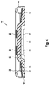
- a switch 10 or 10 ' is shown, in which the temperature-dependent switching mechanism carries a movable contact part, which is in contact with a stationary mating contact, which is contacted by the cover part through outwardly to the first outer contact surface shows Fig. 4 an alternative embodiment of a switch 10, in which on a plastic cover part 55 two stationary mating contacts 56, 57 are arranged.
- the two stationary mating contacts 56, 57 cooperate with a current transfer member 58, which differs from the in Fig. 4 not shown, temperature-dependent switching mechanism is moved.
- the two stationary mating contacts 56, 57 cooperate with two outer contact surfaces 61, 62, with which they are in Fig. 4 not shown manner are electrically connected.
- This switch can also be mounted on a printed circuit board in an SMT manner, two soldering surfaces for the contact surfaces 61, 62 then being provided on the printed circuit board in order to electrically connect the switch.
- annular soldering surface for the curved edge 41 is provided to mechanically fix the switch. If the curved edge is connected along its entire circumference with an annular soldering surface, the curved edge 41 also serves as a barrier against the entry of impurities, as already described above.
- cover part 55 is here made of an insulating plastic, no insulating film is required between the cover part 55 and the lower part, although of course this can also be provided here.
- a protective film 63 is arranged, which serves the sealing between the lower part and the cover part, wherein the curved edge 41 can rest with its end face 42 sealingly on the protective film 63.
Landscapes
- Physics & Mathematics (AREA)
- Thermal Sciences (AREA)
- Thermally Actuated Switches (AREA)
- Switch Cases, Indication, And Locking (AREA)
Priority Applications (3)
| Application Number | Priority Date | Filing Date | Title |
|---|---|---|---|
| DK16178866.6T DK3270401T3 (da) | 2016-07-11 | 2016-07-11 | Temperaturafhængig kontakt med isoleringsskive |
| EP16178866.6A EP3270401B8 (fr) | 2016-07-11 | 2016-07-11 | Commutateur thermique doté de vitre isolante |
| ES16178866T ES2741350T3 (es) | 2016-07-11 | 2016-07-11 | Interruptor dependiente de la temperatura con arandela aislante |
Applications Claiming Priority (1)
| Application Number | Priority Date | Filing Date | Title |
|---|---|---|---|
| EP16178866.6A EP3270401B8 (fr) | 2016-07-11 | 2016-07-11 | Commutateur thermique doté de vitre isolante |
Publications (3)
| Publication Number | Publication Date |
|---|---|
| EP3270401A1 true EP3270401A1 (fr) | 2018-01-17 |
| EP3270401B1 EP3270401B1 (fr) | 2019-05-15 |
| EP3270401B8 EP3270401B8 (fr) | 2019-06-26 |
Family
ID=56684442
Family Applications (1)
| Application Number | Title | Priority Date | Filing Date |
|---|---|---|---|
| EP16178866.6A Active EP3270401B8 (fr) | 2016-07-11 | 2016-07-11 | Commutateur thermique doté de vitre isolante |
Country Status (3)
| Country | Link |
|---|---|
| EP (1) | EP3270401B8 (fr) |
| DK (1) | DK3270401T3 (fr) |
| ES (1) | ES2741350T3 (fr) |
Cited By (1)
| Publication number | Priority date | Publication date | Assignee | Title |
|---|---|---|---|---|
| WO2020108805A1 (fr) * | 2018-11-28 | 2020-06-04 | Hofsaess Marcel P | Commutateur dépendant de la température muni d'un disque isolant |
Citations (9)
| Publication number | Priority date | Publication date | Assignee | Title |
|---|---|---|---|---|
| DE19517310A1 (de) | 1995-05-03 | 1996-11-14 | Thermik Geraetebau Gmbh | Baustein aus Kaltleitermaterial |
| DE19623579A1 (de) | 1996-06-13 | 1997-12-18 | Opel Adam Ag | Kraftfahrzeug-Armaturentafel aus Kunststoff mit einer Airbag-Abdeckung |
| DE19623570A1 (de) | 1996-06-13 | 1998-01-02 | Marcel Hofsaes | Temperaturwächter mit einer Kaptonfolie |
| DE19827113C2 (de) | 1998-06-18 | 2001-11-29 | Marcel Hofsaes | Temperaturabhängiger Schalter mit Stromübertragungsglied |
| DE4143671C2 (de) | 1991-11-28 | 2002-02-28 | Hofsaes Geb Zeitz | Verfahren zur Fertigung eines Temperaturschalters |
| DE102009039948A1 (de) | 2009-08-27 | 2011-03-03 | Hofsaess, Marcel P. | Temperaturabhängiger Schalter |
| EP2654057A1 (fr) * | 2012-04-16 | 2013-10-23 | Marcel P. Hofsaess | Commutateur thermodépendant |
| DE102013102089B4 (de) | 2013-03-04 | 2015-02-12 | Marcel P. HOFSAESS | Temperaturabhängiger Schalter mit Isolierscheibe |
| DE102013102006B4 (de) | 2013-02-28 | 2015-03-05 | Marcel P. HOFSAESS | Temperaturabhängiger Schalter |
-
2016
- 2016-07-11 ES ES16178866T patent/ES2741350T3/es active Active
- 2016-07-11 DK DK16178866.6T patent/DK3270401T3/da active
- 2016-07-11 EP EP16178866.6A patent/EP3270401B8/fr active Active
Patent Citations (9)
| Publication number | Priority date | Publication date | Assignee | Title |
|---|---|---|---|---|
| DE4143671C2 (de) | 1991-11-28 | 2002-02-28 | Hofsaes Geb Zeitz | Verfahren zur Fertigung eines Temperaturschalters |
| DE19517310A1 (de) | 1995-05-03 | 1996-11-14 | Thermik Geraetebau Gmbh | Baustein aus Kaltleitermaterial |
| DE19623579A1 (de) | 1996-06-13 | 1997-12-18 | Opel Adam Ag | Kraftfahrzeug-Armaturentafel aus Kunststoff mit einer Airbag-Abdeckung |
| DE19623570A1 (de) | 1996-06-13 | 1998-01-02 | Marcel Hofsaes | Temperaturwächter mit einer Kaptonfolie |
| DE19827113C2 (de) | 1998-06-18 | 2001-11-29 | Marcel Hofsaes | Temperaturabhängiger Schalter mit Stromübertragungsglied |
| DE102009039948A1 (de) | 2009-08-27 | 2011-03-03 | Hofsaess, Marcel P. | Temperaturabhängiger Schalter |
| EP2654057A1 (fr) * | 2012-04-16 | 2013-10-23 | Marcel P. Hofsaess | Commutateur thermodépendant |
| DE102013102006B4 (de) | 2013-02-28 | 2015-03-05 | Marcel P. HOFSAESS | Temperaturabhängiger Schalter |
| DE102013102089B4 (de) | 2013-03-04 | 2015-02-12 | Marcel P. HOFSAESS | Temperaturabhängiger Schalter mit Isolierscheibe |
Cited By (5)
| Publication number | Priority date | Publication date | Assignee | Title |
|---|---|---|---|---|
| WO2020108805A1 (fr) * | 2018-11-28 | 2020-06-04 | Hofsaess Marcel P | Commutateur dépendant de la température muni d'un disque isolant |
| CN111243904A (zh) * | 2018-11-28 | 2020-06-05 | 马赛尔·P·霍夫萨埃斯 | 具有绝缘盘片的温控开关 |
| EP3660877A3 (fr) * | 2018-11-28 | 2020-07-29 | Marcel P. Hofsaess | Commutateur dépendant de la température pourvu de vitre isolante |
| US11195679B2 (en) | 2018-11-28 | 2021-12-07 | Marcel P. HOFSAESS | Temperature-dependent switch |
| CN111243904B (zh) * | 2018-11-28 | 2022-12-30 | 马赛尔·P·霍夫萨埃斯 | 具有绝缘盘片的温控开关 |
Also Published As
| Publication number | Publication date |
|---|---|
| DK3270401T3 (da) | 2019-08-12 |
| EP3270401B1 (fr) | 2019-05-15 |
| EP3270401B8 (fr) | 2019-06-26 |
| ES2741350T3 (es) | 2020-02-10 |
Similar Documents
| Publication | Publication Date | Title |
|---|---|---|
| DE102013102006B4 (de) | Temperaturabhängiger Schalter | |
| EP2775495B1 (fr) | Commutateur thermosensible avec plaque isolante | |
| DE102009039948A1 (de) | Temperaturabhängiger Schalter | |
| DE19609310C2 (de) | Schalter mit einem temperaturabhängigen Schaltwerk | |
| EP4369374B1 (fr) | Commutateur dépendant de la température | |
| EP0858090B1 (fr) | Thermostat avec un dispositif interrupteur à bimétal | |
| EP3828912B1 (fr) | Commutateur dépendant de la température | |
| DE102015110509B4 (de) | Temperaturabhängiger Schalter mit lsolierscheibe und elektronische Schaltung mit einemauf einer Leiterplatte montierten, temperaturabhängigen Schalter | |
| EP3136416B1 (fr) | Commutateur thermodépendant comprenant un dispositif de coupe | |
| EP3796360B1 (fr) | Commutateur dépendant de la température | |
| EP3660877B1 (fr) | Dispositif comprenant commutateur dépendant de la température et un capuchon de montage métallique | |
| EP2743954B1 (fr) | Commutateur thermodépendant | |
| EP2654057B1 (fr) | Commutateur thermodépendant | |
| EP2978007A1 (fr) | Commutateur thermosensible avec film isolant | |
| EP3270401B1 (fr) | Commutateur thermique doté de vitre isolante | |
| DE102019111279B4 (de) | Temperaturabhängiger Schalter | |
| DE102015017281B3 (de) | Temperaturabhängiger Schalter mit Isolierscheibe und elektronische Schaltung |
Legal Events
| Date | Code | Title | Description |
|---|---|---|---|
| PUAI | Public reference made under article 153(3) epc to a published international application that has entered the european phase |
Free format text: ORIGINAL CODE: 0009012 |
|
| STAA | Information on the status of an ep patent application or granted ep patent |
Free format text: STATUS: THE APPLICATION HAS BEEN PUBLISHED |
|
| AK | Designated contracting states |
Kind code of ref document: A1 Designated state(s): AL AT BE BG CH CY CZ DE DK EE ES FI FR GB GR HR HU IE IS IT LI LT LU LV MC MK MT NL NO PL PT RO RS SE SI SK SM TR |
|
| AX | Request for extension of the european patent |
Extension state: BA ME |
|
| STAA | Information on the status of an ep patent application or granted ep patent |
Free format text: STATUS: REQUEST FOR EXAMINATION WAS MADE |
|
| 17P | Request for examination filed |
Effective date: 20180530 |
|
| RBV | Designated contracting states (corrected) |
Designated state(s): AL AT BE BG CH CY CZ DE DK EE ES FI FR GB GR HR HU IE IS IT LI LT LU LV MC MK MT NL NO PL PT RO RS SE SI SK SM TR |
|
| GRAP | Despatch of communication of intention to grant a patent |
Free format text: ORIGINAL CODE: EPIDOSNIGR1 |
|
| STAA | Information on the status of an ep patent application or granted ep patent |
Free format text: STATUS: GRANT OF PATENT IS INTENDED |
|
| RIC1 | Information provided on ipc code assigned before grant |
Ipc: H01H 37/04 20060101ALI20181029BHEP Ipc: H01H 37/54 20060101AFI20181029BHEP |
|
| INTG | Intention to grant announced |
Effective date: 20181119 |
|
| GRAS | Grant fee paid |
Free format text: ORIGINAL CODE: EPIDOSNIGR3 |
|
| GRAJ | Information related to disapproval of communication of intention to grant by the applicant or resumption of examination proceedings by the epo deleted |
Free format text: ORIGINAL CODE: EPIDOSDIGR1 |
|
| GRAL | Information related to payment of fee for publishing/printing deleted |
Free format text: ORIGINAL CODE: EPIDOSDIGR3 |
|
| STAA | Information on the status of an ep patent application or granted ep patent |
Free format text: STATUS: REQUEST FOR EXAMINATION WAS MADE |
|
| GRAR | Information related to intention to grant a patent recorded |
Free format text: ORIGINAL CODE: EPIDOSNIGR71 |
|
| STAA | Information on the status of an ep patent application or granted ep patent |
Free format text: STATUS: GRANT OF PATENT IS INTENDED |
|
| GRAA | (expected) grant |
Free format text: ORIGINAL CODE: 0009210 |
|
| STAA | Information on the status of an ep patent application or granted ep patent |
Free format text: STATUS: THE PATENT HAS BEEN GRANTED |
|
| INTC | Intention to grant announced (deleted) | ||
| GRAT | Correction requested after decision to grant or after decision to maintain patent in amended form |
Free format text: ORIGINAL CODE: EPIDOSNCDEC |
|
| INTG | Intention to grant announced |
Effective date: 20190403 |
|
| AK | Designated contracting states |
Kind code of ref document: B1 Designated state(s): AL AT BE BG CH CY CZ DE DK EE ES FI FR GB GR HR HU IE IS IT LI LT LU LV MC MK MT NL NO PL PT RO RS SE SI SK SM TR |
|
| REG | Reference to a national code |
Ref country code: CH Ref legal event code: EP |
|
| REG | Reference to a national code |
Ref country code: DE Ref legal event code: R108 Ref document number: 502016004677 Country of ref document: DE |
|
| REG | Reference to a national code |
Ref country code: CH Ref legal event code: PK Free format text: BERICHTIGUNG B8 |
|
| RBV | Designated contracting states (corrected) |
Designated state(s): AL AT BE BG CH CY CZ DE DK EE ES FI FR GB GR HR HU IE IS IT LI LT LU LV MC MK MT NL NO PL PT RO RS SE SI SK SM TR |
|
| REG | Reference to a national code |
Ref country code: DE Ref legal event code: R096 Ref document number: 502016004677 Country of ref document: DE |
|
| RBV | Designated contracting states (corrected) |
Designated state(s): AL AT BE BG CH CY CZ DK EE ES FI FR GB GR HR HU IE IS IT LI LT LU LV MC MK MT NL NO PL PT RO RS SE SI SK SM TR |
|
| REG | Reference to a national code |
Ref country code: IE Ref legal event code: FG4D Free format text: LANGUAGE OF EP DOCUMENT: GERMAN |
|
| REG | Reference to a national code |
Ref country code: CH Ref legal event code: NV Representative=s name: RENTSCH PARTNER AG, CH |
|
| REG | Reference to a national code |
Ref country code: DE Ref legal event code: R107 Ref document number: 502016004677 Country of ref document: DE |
|
| REG | Reference to a national code |
Ref country code: DK Ref legal event code: T3 Effective date: 20190809 |
|
| REG | Reference to a national code |
Ref country code: NL Ref legal event code: FP |
|
| REG | Reference to a national code |
Ref country code: SE Ref legal event code: TRGR |
|
| REG | Reference to a national code |
Ref country code: LT Ref legal event code: MG4D |
|
| PG25 | Lapsed in a contracting state [announced via postgrant information from national office to epo] |
Ref country code: AL Free format text: LAPSE BECAUSE OF FAILURE TO SUBMIT A TRANSLATION OF THE DESCRIPTION OR TO PAY THE FEE WITHIN THE PRESCRIBED TIME-LIMIT Effective date: 20190515 Ref country code: PT Free format text: LAPSE BECAUSE OF FAILURE TO SUBMIT A TRANSLATION OF THE DESCRIPTION OR TO PAY THE FEE WITHIN THE PRESCRIBED TIME-LIMIT Effective date: 20190915 Ref country code: NO Free format text: LAPSE BECAUSE OF FAILURE TO SUBMIT A TRANSLATION OF THE DESCRIPTION OR TO PAY THE FEE WITHIN THE PRESCRIBED TIME-LIMIT Effective date: 20190815 Ref country code: FI Free format text: LAPSE BECAUSE OF FAILURE TO SUBMIT A TRANSLATION OF THE DESCRIPTION OR TO PAY THE FEE WITHIN THE PRESCRIBED TIME-LIMIT Effective date: 20190515 Ref country code: LT Free format text: LAPSE BECAUSE OF FAILURE TO SUBMIT A TRANSLATION OF THE DESCRIPTION OR TO PAY THE FEE WITHIN THE PRESCRIBED TIME-LIMIT Effective date: 20190515 Ref country code: HR Free format text: LAPSE BECAUSE OF FAILURE TO SUBMIT A TRANSLATION OF THE DESCRIPTION OR TO PAY THE FEE WITHIN THE PRESCRIBED TIME-LIMIT Effective date: 20190515 |
|
| PGFP | Annual fee paid to national office [announced via postgrant information from national office to epo] |
Ref country code: IE Payment date: 20190724 Year of fee payment: 4 |
|
| PG25 | Lapsed in a contracting state [announced via postgrant information from national office to epo] |
Ref country code: LV Free format text: LAPSE BECAUSE OF FAILURE TO SUBMIT A TRANSLATION OF THE DESCRIPTION OR TO PAY THE FEE WITHIN THE PRESCRIBED TIME-LIMIT Effective date: 20190515 Ref country code: RS Free format text: LAPSE BECAUSE OF FAILURE TO SUBMIT A TRANSLATION OF THE DESCRIPTION OR TO PAY THE FEE WITHIN THE PRESCRIBED TIME-LIMIT Effective date: 20190515 Ref country code: GR Free format text: LAPSE BECAUSE OF FAILURE TO SUBMIT A TRANSLATION OF THE DESCRIPTION OR TO PAY THE FEE WITHIN THE PRESCRIBED TIME-LIMIT Effective date: 20190816 Ref country code: BG Free format text: LAPSE BECAUSE OF FAILURE TO SUBMIT A TRANSLATION OF THE DESCRIPTION OR TO PAY THE FEE WITHIN THE PRESCRIBED TIME-LIMIT Effective date: 20190815 |
|
| PGFP | Annual fee paid to national office [announced via postgrant information from national office to epo] |
Ref country code: BE Payment date: 20190718 Year of fee payment: 4 |
|
| PG25 | Lapsed in a contracting state [announced via postgrant information from national office to epo] |
Ref country code: CZ Free format text: LAPSE BECAUSE OF FAILURE TO SUBMIT A TRANSLATION OF THE DESCRIPTION OR TO PAY THE FEE WITHIN THE PRESCRIBED TIME-LIMIT Effective date: 20190515 Ref country code: SK Free format text: LAPSE BECAUSE OF FAILURE TO SUBMIT A TRANSLATION OF THE DESCRIPTION OR TO PAY THE FEE WITHIN THE PRESCRIBED TIME-LIMIT Effective date: 20190515 Ref country code: EE Free format text: LAPSE BECAUSE OF FAILURE TO SUBMIT A TRANSLATION OF THE DESCRIPTION OR TO PAY THE FEE WITHIN THE PRESCRIBED TIME-LIMIT Effective date: 20190515 |
|
| PGFP | Annual fee paid to national office [announced via postgrant information from national office to epo] |
Ref country code: CH Payment date: 20190719 Year of fee payment: 4 |
|
| REG | Reference to a national code |
Ref country code: ES Ref legal event code: FG2A Ref document number: 2741350 Country of ref document: ES Kind code of ref document: T3 Effective date: 20200210 |
|
| PG25 | Lapsed in a contracting state [announced via postgrant information from national office to epo] |
Ref country code: SM Free format text: LAPSE BECAUSE OF FAILURE TO SUBMIT A TRANSLATION OF THE DESCRIPTION OR TO PAY THE FEE WITHIN THE PRESCRIBED TIME-LIMIT Effective date: 20190515 Ref country code: MC Free format text: LAPSE BECAUSE OF FAILURE TO SUBMIT A TRANSLATION OF THE DESCRIPTION OR TO PAY THE FEE WITHIN THE PRESCRIBED TIME-LIMIT Effective date: 20190515 |
|
| PLBE | No opposition filed within time limit |
Free format text: ORIGINAL CODE: 0009261 |
|
| STAA | Information on the status of an ep patent application or granted ep patent |
Free format text: STATUS: NO OPPOSITION FILED WITHIN TIME LIMIT |
|
| PG25 | Lapsed in a contracting state [announced via postgrant information from national office to epo] |
Ref country code: TR Free format text: LAPSE BECAUSE OF FAILURE TO SUBMIT A TRANSLATION OF THE DESCRIPTION OR TO PAY THE FEE WITHIN THE PRESCRIBED TIME-LIMIT Effective date: 20190515 |
|
| 26N | No opposition filed |
Effective date: 20200218 |
|
| PG25 | Lapsed in a contracting state [announced via postgrant information from national office to epo] |
Ref country code: PL Free format text: LAPSE BECAUSE OF FAILURE TO SUBMIT A TRANSLATION OF THE DESCRIPTION OR TO PAY THE FEE WITHIN THE PRESCRIBED TIME-LIMIT Effective date: 20190515 |
|
| PG25 | Lapsed in a contracting state [announced via postgrant information from national office to epo] |
Ref country code: SI Free format text: LAPSE BECAUSE OF FAILURE TO SUBMIT A TRANSLATION OF THE DESCRIPTION OR TO PAY THE FEE WITHIN THE PRESCRIBED TIME-LIMIT Effective date: 20190515 Ref country code: LU Free format text: LAPSE BECAUSE OF NON-PAYMENT OF DUE FEES Effective date: 20190711 |
|
| REG | Reference to a national code |
Ref country code: CH Ref legal event code: PL |
|
| GBPC | Gb: european patent ceased through non-payment of renewal fee |
Effective date: 20200711 |
|
| REG | Reference to a national code |
Ref country code: BE Ref legal event code: MM Effective date: 20200731 |
|
| PG25 | Lapsed in a contracting state [announced via postgrant information from national office to epo] |
Ref country code: GB Free format text: LAPSE BECAUSE OF NON-PAYMENT OF DUE FEES Effective date: 20200711 Ref country code: LI Free format text: LAPSE BECAUSE OF NON-PAYMENT OF DUE FEES Effective date: 20200731 Ref country code: RO Free format text: LAPSE BECAUSE OF FAILURE TO SUBMIT A TRANSLATION OF THE DESCRIPTION OR TO PAY THE FEE WITHIN THE PRESCRIBED TIME-LIMIT Effective date: 20190515 Ref country code: CH Free format text: LAPSE BECAUSE OF NON-PAYMENT OF DUE FEES Effective date: 20200731 |
|
| PG25 | Lapsed in a contracting state [announced via postgrant information from national office to epo] |
Ref country code: BE Free format text: LAPSE BECAUSE OF NON-PAYMENT OF DUE FEES Effective date: 20200731 Ref country code: CY Free format text: LAPSE BECAUSE OF FAILURE TO SUBMIT A TRANSLATION OF THE DESCRIPTION OR TO PAY THE FEE WITHIN THE PRESCRIBED TIME-LIMIT Effective date: 20190515 |
|
| PG25 | Lapsed in a contracting state [announced via postgrant information from national office to epo] |
Ref country code: IS Free format text: LAPSE BECAUSE OF FAILURE TO SUBMIT A TRANSLATION OF THE DESCRIPTION OR TO PAY THE FEE WITHIN THE PRESCRIBED TIME-LIMIT Effective date: 20190915 |
|
| PG25 | Lapsed in a contracting state [announced via postgrant information from national office to epo] |
Ref country code: MT Free format text: LAPSE BECAUSE OF FAILURE TO SUBMIT A TRANSLATION OF THE DESCRIPTION OR TO PAY THE FEE WITHIN THE PRESCRIBED TIME-LIMIT Effective date: 20190515 Ref country code: HU Free format text: LAPSE BECAUSE OF FAILURE TO SUBMIT A TRANSLATION OF THE DESCRIPTION OR TO PAY THE FEE WITHIN THE PRESCRIBED TIME-LIMIT; INVALID AB INITIO Effective date: 20160711 |
|
| PG25 | Lapsed in a contracting state [announced via postgrant information from national office to epo] |
Ref country code: IE Free format text: LAPSE BECAUSE OF NON-PAYMENT OF DUE FEES Effective date: 20200711 |
|
| PG25 | Lapsed in a contracting state [announced via postgrant information from national office to epo] |
Ref country code: MK Free format text: LAPSE BECAUSE OF FAILURE TO SUBMIT A TRANSLATION OF THE DESCRIPTION OR TO PAY THE FEE WITHIN THE PRESCRIBED TIME-LIMIT Effective date: 20190515 |
|
| P01 | Opt-out of the competence of the unified patent court (upc) registered |
Effective date: 20230508 |
|
| PGFP | Annual fee paid to national office [announced via postgrant information from national office to epo] |
Ref country code: NL Payment date: 20250721 Year of fee payment: 10 |
|
| PGFP | Annual fee paid to national office [announced via postgrant information from national office to epo] |
Ref country code: ES Payment date: 20250826 Year of fee payment: 10 |
|
| PGFP | Annual fee paid to national office [announced via postgrant information from national office to epo] |
Ref country code: DK Payment date: 20250725 Year of fee payment: 10 |
|
| PGFP | Annual fee paid to national office [announced via postgrant information from national office to epo] |
Ref country code: IT Payment date: 20250724 Year of fee payment: 10 |
|
| PGFP | Annual fee paid to national office [announced via postgrant information from national office to epo] |
Ref country code: FR Payment date: 20250725 Year of fee payment: 10 Ref country code: AT Payment date: 20250722 Year of fee payment: 10 |
|
| PGFP | Annual fee paid to national office [announced via postgrant information from national office to epo] |
Ref country code: SE Payment date: 20250722 Year of fee payment: 10 |