EP3270463B1 - Bildgebungsarray-gespeister reflektor - Google Patents
Bildgebungsarray-gespeister reflektor Download PDFInfo
- Publication number
- EP3270463B1 EP3270463B1 EP17176140.6A EP17176140A EP3270463B1 EP 3270463 B1 EP3270463 B1 EP 3270463B1 EP 17176140 A EP17176140 A EP 17176140A EP 3270463 B1 EP3270463 B1 EP 3270463B1
- Authority
- EP
- European Patent Office
- Prior art keywords
- antenna system
- beam antenna
- amplifier
- beamlet
- radiating
- Prior art date
- Legal status (The legal status is an assumption and is not a legal conclusion. Google has not performed a legal analysis and makes no representation as to the accuracy of the status listed.)
- Active
Links
Images




Classifications
-
- H—ELECTRICITY
- H01—ELECTRIC ELEMENTS
- H01Q—ANTENNAS, i.e. RADIO AERIALS
- H01Q21/00—Antenna arrays or systems
- H01Q21/06—Arrays of individually energised antenna units similarly polarised and spaced apart
- H01Q21/061—Two dimensional planar arrays
- H01Q21/067—Two dimensional planar arrays using endfire radiating aerial units transverse to the plane of the array
-
- H—ELECTRICITY
- H01—ELECTRIC ELEMENTS
- H01Q—ANTENNAS, i.e. RADIO AERIALS
- H01Q15/00—Devices for reflection, refraction, diffraction or polarisation of waves radiated from an antenna, e.g. quasi-optical devices
- H01Q15/14—Reflecting surfaces; Equivalent structures
-
- H—ELECTRICITY
- H01—ELECTRIC ELEMENTS
- H01Q—ANTENNAS, i.e. RADIO AERIALS
- H01Q1/00—Details of, or arrangements associated with, antennas
- H01Q1/27—Adaptation for use in or on movable bodies
- H01Q1/28—Adaptation for use in or on aircraft, missiles, satellites, or balloons
-
- H—ELECTRICITY
- H01—ELECTRIC ELEMENTS
- H01Q—ANTENNAS, i.e. RADIO AERIALS
- H01Q1/00—Details of, or arrangements associated with, antennas
- H01Q1/27—Adaptation for use in or on movable bodies
- H01Q1/28—Adaptation for use in or on aircraft, missiles, satellites, or balloons
- H01Q1/288—Satellite antennas
-
- H—ELECTRICITY
- H01—ELECTRIC ELEMENTS
- H01Q—ANTENNAS, i.e. RADIO AERIALS
- H01Q19/00—Combinations of primary active antenna elements and units with secondary devices, e.g. with quasi-optical devices, for giving the antenna a desired directional characteristic
- H01Q19/10—Combinations of primary active antenna elements and units with secondary devices, e.g. with quasi-optical devices, for giving the antenna a desired directional characteristic using reflecting surfaces
-
- H—ELECTRICITY
- H01—ELECTRIC ELEMENTS
- H01Q—ANTENNAS, i.e. RADIO AERIALS
- H01Q19/00—Combinations of primary active antenna elements and units with secondary devices, e.g. with quasi-optical devices, for giving the antenna a desired directional characteristic
- H01Q19/10—Combinations of primary active antenna elements and units with secondary devices, e.g. with quasi-optical devices, for giving the antenna a desired directional characteristic using reflecting surfaces
- H01Q19/12—Combinations of primary active antenna elements and units with secondary devices, e.g. with quasi-optical devices, for giving the antenna a desired directional characteristic using reflecting surfaces wherein the surfaces are concave
- H01Q19/17—Combinations of primary active antenna elements and units with secondary devices, e.g. with quasi-optical devices, for giving the antenna a desired directional characteristic using reflecting surfaces wherein the surfaces are concave the primary radiating source comprising two or more radiating elements
-
- H—ELECTRICITY
- H01—ELECTRIC ELEMENTS
- H01Q—ANTENNAS, i.e. RADIO AERIALS
- H01Q21/00—Antenna arrays or systems
- H01Q21/06—Arrays of individually energised antenna units similarly polarised and spaced apart
- H01Q21/061—Two dimensional planar arrays
- H01Q21/064—Two dimensional planar arrays using horn or slot aerials
-
- H—ELECTRICITY
- H01—ELECTRIC ELEMENTS
- H01Q—ANTENNAS, i.e. RADIO AERIALS
- H01Q21/00—Antenna arrays or systems
- H01Q21/06—Arrays of individually energised antenna units similarly polarised and spaced apart
- H01Q21/22—Antenna units of the array energised non-uniformly in amplitude or phase, e.g. tapered array or binomial array
-
- H—ELECTRICITY
- H01—ELECTRIC ELEMENTS
- H01Q—ANTENNAS, i.e. RADIO AERIALS
- H01Q25/00—Antennas or antenna systems providing at least two radiating patterns
- H01Q25/007—Antennas or antenna systems providing at least two radiating patterns using two or more primary active elements in the focal region of a focusing device
-
- H—ELECTRICITY
- H04—ELECTRIC COMMUNICATION TECHNIQUE
- H04B—TRANSMISSION
- H04B7/00—Radio transmission systems, i.e. using radiation field
- H04B7/14—Relay systems
- H04B7/15—Active relay systems
- H04B7/204—Multiple access
- H04B7/2041—Spot beam multiple access
Definitions
- the present disclosure relates generally to satellite antennas, and particularly to an imaging array fed reflector for a high throughput satellite payload.
- the assignee of the present invention manufactures and deploys spacecraft for, inter alia, communications and broadcast services.
- Market demands for such spacecraft have imposed increasingly stringent requirements on spacecraft payloads.
- broadband service providers desire spacecraft with increased data rate capacity at higher EIRP through each of an increased number of user spot beans operable from geosynchronous orbit altitudes in communication with small ( ⁇ 1 meter aperture) user terminals.
- a multi-beam antenna (MBA) system generates a set of user spot beams that define a coverage area which may extend, in aggregate, across a large region on the ground.
- MBAs providing wide-band communications services from a geosynchronous satellite conventionally provide contiguous coverage of a region with a triangular lattice of overlapping circular antenna beams. These beams are conventionally formed using clusters of radiating elements configured as circular feed horns, also centered on a triangular lattice.
- An objective of an MBA system is to maximize beam forming efficiency, measured as gain area product (GAP) of the MBA divided by 4 ⁇ steradians (41,253 square degrees).
- GAP G ave *A cov , where G ave is the average gain over coverage area, A cov , with A cov expressed in square degrees.
- Known MBA systems provide a GAP of 10000-16000 and, therefore, a beam forming efficiency in the range of 24% to 39%. See: Han, C.C., etal., "Satellite Antennas", Antenna Handbook, volume 3, chapter 21, edited by Lo, Y.T., etal., ISBN 0-442-01594-1 (hereinafter, "Han").
- US2015295640A1 discloses a spacecraft that includes a payload subsystem, the payload subsystem including a phased array of feed elements configured to illuminate an antenna reflector, a beam forming network (BFN) disposed proximate to the array of feed elements, and a plurality of power amplifiers disposed between the BFN and the array of feed elements.
- BFN beam forming network
- US2009262037A1 discloses an antenna system for generating and distributing power among a plurality of non-focused beams, the system comprises a reflector having a focal plane and a non-parabolic curvature configured to form the defocused beams.
- US2003076274A1 discloses an antenna array that includes a plurality of periodic or aperiodic arranged sub-arrays.
- a single aperture, array fed reflector MBA may share radiating elements between two or more beams, complicating the beamforming and requiring multi-carrier operation.
- Multi-carrier operation requires linearity which leads to output back-off of the amplifiers and reduced amplifier efficiency with increased power and heat generated for a given output power.
- an arrangement having a single feed horn per beam with a conventional multi-reflector MBA requires higher power amplifiers and amplifier redundancy, with increased cost and complexity.
- an MBA having a single feed per beam is generally scan limited by reflector offset distortion.
- a multi-beam antenna (MBA) system for a spacecraft as set out in the appending independent claim.
- MSA multi-beam antenna
- a spacecraft comprising a communications payload subsystem, the payload subsystem including a multi-beam antenna system as set out in the appending independent claim.
- Fig. 10 The example illustrated in Fig. 10 is not according to the invention and is present for illustration purposes only.
- spacecraft spacecraft
- spacecraft spacecraft
- satellite spacecraft
- vehicle vehicle
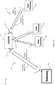
- the network includes a satellite 111, which may be located, for example, at a geostationary orbital location or in low earth orbit. Satellite 111 may be communicatively coupled, via at least one feeder link antenna 121, to at least one gateway 112 and, via at least one user link antenna 122 to a plurality of user terminals 116.
- the at least one gateway 112 may be coupled to a network such as, for example, the Internet.
- Each gateway 112 and the satellite 111 communicate over a feeder link 113, which has both a forward uplink 114 and a return downlink 115.
- User terminals 116 and the satellite 111 communicate over a user link 117 that has both a forward downlink 118 and a return uplink 119.
- User link 117 and the feeder link may operate in respective assigned frequency bands, referred to herein as the "user link band” and the “feeder link band.”
- One or more of the feeder link antenna 121 and the user link antenna 122 may include a high efficiency multi-beam antenna (MBA) system of the type disclosed in US9153877 .
- the antenna reflector may be substantially oversized with respect to a reflector conventionally sized to produce a circular beam that is 4-4.5 dB down at the edge of coverage.
- the payload subsystem 100B may include receive antenna feeds 105 illuminated by feeder link antenna 121, filters 115, low-noise amplifiers (LNAs) 125, frequency converters, including input local oscillators 135, including output local oscillators 145, amplifiers 150, which may or may not include linearization, and radiating feed elements 165 that illuminate user link antenna 122.
- the user link antenna 122 may include a reflector.
- the payload subsystem 100B may include a digital channelizer 170.
- the digital channelizer 170 may receive analog RF input signals by way of a quantity 'N' of receive ports, where 'N' is greater than or equal to 1.
- the digital channelizer 170 may enable the payload subsystem 100B to process multiple input signals and to reconfigurably distribute portions of those input signals into multiple output signals and to create reconfigurable channels to route the multiple input signals to multiple output ports.
- the digital channelizer 170 may include analog-to-digital converters, digital-to-analog converters, control computer(s) with software or firmware, and signal processing electronics (not illustrated).
- the digital channelizer 170 may forward analog RF output signals by way of a quantity 'M' of transmit ports, where 'M' is greater than or equal to 1. It will be appreciated that quantity 'M' is not necessarily equal to quantity 'N'.
- the multiple inputs and outputs provide redundancy for the payload 110, in addition to redundancy within the channelizer.
- the digital channelizer 170 may be capable of operating over all or a substantial part of the bandwidth ranges that are allocated to the payload subsystem 100B.
- the digital channelizer 170 may sub-divide the uplink frequency spectrum into smaller segments and permit fine bandwidth adjustability in the smaller segments.
- the digital channelizer 170 may also tune, in fine or coarse increments, responsive to ground and/or onboard commands, the channel center frequency and bandwidth allocated to a particular uplink beam on a communications satellite, in addition to adjusting the frequency response curve and other characteristics of each channel.
- the digital channelizer 170 may directly handle uplink frequencies and/or downlink frequencies, thus, in some implementations, replacing some or all of the filters 115, the input frequency converters 135 and output frequency converters 145.
- Other functions of a digital channelizer may include frequency conversion, demodulation, bit detection, and modulation, among others.
- a spacecraft payload subsystem may be configured to include a digital channelizer as illustrated in Figure 1B ; however, in some implementations the payload subsystem may not include a digital channelizer.
- each of a large number of beams is formed by a respective dedicated cluster of elements with no element sharing between beams.
- Figure 2 illustrates an example of an active phased array.
- an active phased array 200 is configured to provide forty-two beams, each beam formed by a cluster of seven dedicated radiating elements.
- beam number 1 is illustrated to be formed by radiating elements located at positions a, b, c, d, e, f and g. It may be observed that each radiating element is associated with a single respective beam.
- each radiating element is coupled with a respective amplifier module disposed proximate to the radiating element.
- the beams are arranged in a close packed triangular lattice; likewise, the radiating elements are arranged in a close packed triangular lattice.
- each radiating element and a respective amplifier and related electronics may be arranged so as to be contained within a rectangular footprint area having an aspect ratio of short wall to long wall of 3 2 : 1 .
- each radiating element and a respective amplifier and related electronics may be arranged so as to be contained within a hexagonal footprint area.
- the footprint area is, advantageously, 3 2 times the spacing between adjacent elements ("element spacing") squared, in order to maximize packing efficiency.
- the element spacing may, advantageously, be small, for example less than 3 ⁇ . In an implementation, the element spacing is 1.1 ⁇ .
- each beam is associated with seven radiating feed elements.
- Figure 3 illustrates a comparison of an arrangement for a beam being associated with seven radiating feed elements (Detail A) with an arrangement for a beam being associated with nineteen radiating feed elements (Detail B) and with an arrangement for a beams associated with thirty-seven radiating feed elements (Detail C).
- FIG. 4 illustrates an isometric view of an active phased array for a single beam including nineteen beamlets using helical radiating feed elements, according to an implementation.
- the active phased array 400 includes nineteen radiating feed elements 401 arranged in a triangular lattice, and may be configured to form a single beam.
- radiating feed element spacing may be electrically small (e.g., typically, 1.1 ⁇ ).
- the radiating element may be chosen to provide maximum aperture efficiency in the regime where the element spacing is less than 2 ⁇ .
- Examples of radiating feed elements suitable for operation with the disclosed techniques may include end fire elements.
- a radiating element may be configured as a cupped helix, a Yagi or crossed Yagi antenna element, a log-periodic antenna element, or a stacked patch antenna element.
- the radiating feed element is configured as a cupped helix (helical) antenna.
- a helical antenna is an electromagnetic radiator made of a conducting wire wound in the form of a screw thread forming a helix. The pattern of a single turn determines polarization along the axis while the array determines the pattern shape. A circular cup around the feed point reduces the excitation of unwanted modes.
- the helix may be connected, at a feed point, to a center conductor of a coaxial transmission line.
- An outer conductor of the coaxial transmission line may be attached to a ground plane.
- the ground plane may take different forms. For example, in some implementations, the ground plane may be flat.
- the ground plane may be cupped in the form of a cylindrical cavity or in the form of a frustum cavity.
- other types of feeds such as waveguides and dielectric rods are within the contemplation of the present disclosure.
- the helical radiating element In the end-fire, or axial, mode of operation, the helical radiating element has a single major lobe, the major lobe exhibiting a maximum radiation intensity along the axis of the helix. Minor lobes may be disposed at oblique angles to the axis.
- the radiating feed element can be a Yagi (Yagi-Uda) or crossed Yagi antenna element that includes a number of linear dipole elements, one of which is energized directly by a feed transmission line, others of which act as parasitic radiators having currents induced by mutual coupling.
- Yagi Yagi-Uda
- crossed Yagi antenna element that includes a number of linear dipole elements, one of which is energized directly by a feed transmission line, others of which act as parasitic radiators having currents induced by mutual coupling.
- the radiating feed element may be a log-periodic antenna element. While similar to the Yagi-Uda array, in which only one element is directly energized by the feed line and the others operate in a parasitic mode, all the elements of the log-periodic array are coupled with a feed. In a log-periodic antenna, the antenna is fed at the small end of the structure. This produces an end-fire beam in the direction of the longer elements.
- the radiating feed element may be a stacked microstrip patch antenna element.
- Microstrip antennas may include a very thin metallic strip (patch) placed a small fraction of a wavelength above a ground plane.
- the microstrip patch is designed so its pattern maximum is normal to the patch. This may be accomplished by appropriately choosing the mode (field configuration) of excitation beneath the patch. End-fire radiation can be accomplished by mode selection.
- each radiating element is coupled with a respective amplifier module disposed proximate to the radiating element.
- the active phased array contemplated by the present disclosure includes a large number of small solid state amplifiers (SSPAs), one per feed element-polarization, which may be optimally located very near to the radiating elements in order to minimize line losses.
- SSPAs small solid state amplifiers
- the power amplifier arrangements may be produced by SMT (surface mount technology) component placement systems, or pick-and-place machines, which are robotic machines used to place surface-mount devices (SMDs) onto a printed circuit board (PCB).
- SMT surface mount technology
- pick-and-place machines robotic machines used to place surface-mount devices (SMDs) onto a printed circuit board (PCB).
- each radiating feed element may be associated with at least one gallium nitride (GaN) SSPA.
- GaN SSPAs represent an alternative technology to TWTAs in high throughput satellite architectures.
- An active phased array including GaN SSPAs may be configured to produce hundreds of overlapping downlink user beams while obviating a need for travelling wave tube amplifiers, R-switches, output multiplexer filters and waveguide that might otherwise be required.
- Each feed element may be communicatively coupled with a separate power amplifier for each respective polarization at which the feed element is intended to operate.
- the power amplifiers may, advantageously, be located very near to the feed elements in order to minimize line losses.
- output waveguides that would be required in the absence of the present teachings, may be omitted from the forward path.
- the number of components, mass and complexity of a phased array are all reduced.
- each power amplifier is fed by coaxial cable (rather than a waveguide) and configured such that, for example, an end-fire helical radiating antenna feed element plugs directly into the power amplifier.
- one or more of the power amplifiers may be configured in a variant of the known Doherty configuration.
- a Doherty amplifier may provide high efficiency over an output backoff power range associated with the linearity profile required for bandwidth efficient modulation and coding waveforms.
- a Doherty amplifier may include relatively linear amplifiers, which are known to have lower efficiency at lower power levels. As a result, in modulation schemes that have high peak to average power ratio, a high efficiency is still obtained at back-off points.
- a Doherty amplifier may use one main power amplifier (PA) and one auxiliary PA. At maximum output power, both PAs contribute equally to the output. When decreasing the input drive level to, for example, half the maximum combined output power, the auxiliary PA may be configured to shut down.
- PA main power amplifier
- each radiating element illuminates a single large reflector to produce a very small beamlet in the reflector far-field.
- E- and H-field components are orthogonal to each other.
- the size of the beamlet is a function of the wavelength of the signal and the reflector diameter.
- nineteen beamlets may be combined to form a single beam.
- Figure 5 illustrates an example of interleaving of a number of such beams, each beam having nineteen radiating elements.
- a 9 meter diameter reflector is contemplated that will produce a beamlet of about 0.1 degree in the 20 GHz band.
- Adjacent radiating elements will produce adjacent beamlets in the far-field at a spacing determined by the element spacing and the focal length of the reflector.
- the beamlet spacing will be about 0.07 degrees. Because the beamlet spacing is less than the beamlet width, clusters of overlapping beamlets will efficiently combine in the far-field to produce an antenna pattern which is an image of the feed element cluster. Accordingly, the phased array may be referred to as an "imaging array" of which the beamlets may be regarded as pixels that produce the image.
- a beam diameter and spacing may be determined for any particular desired operating frequency and antenna efficiency.
- the presently disclosed techniques improve multi beam antenna efficiency by as much as 70% compared to conventional multi beam antennas. Because radiating feed elements are not shared between beams, beamforming circuitry is simplified to a small circuit card per beam. In some implementations, single carrier per beam operation is contemplated, which relaxes backoff requirements due to lower linearity requirements relative to multicarrier operation, and thus allows all amplifiers for a beam to be operated at maximum efficiency. In some implementations, multiple amplifiers per beam enable soft redundancy and eliminate a requirement for sparing and associated costs.
- soft redundancy means that in the event that one of the amplifiers used to form the antenna beam fails, the beam shape may be reformed by re-optimizing the amplitude and phase coefficients to the remaining amplifiers. Soft redundancy may obviate a need to provide spare amplifiers.
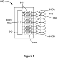
- FIG. 6 illustrates an example implementation of soft redundancy.
- the beam forming network (BFN) 640 in the illustrated implementation, is configured to perform seven element beam forming.
- the BFN 640 includes 1:7 power splitter 642, and commandable variable amplitude and phase (VAP) adjusting arrangements 644.
- VAP variable amplitude and phase
- one or more of the VAP adjusting arrangements 644 may be implemented as a monolithic microwave integrated circuit (MMIC) chip.
- MMIC monolithic microwave integrated circuit
- Each of the seven VAP adjusting arrangements 644 is communicatively coupled with a single power amplifier 650, which is communicatively coupled with a single corresponding feed element 660.
- the beam shape may be reformed by re-optimizing the amplitude and phase coefficients for remaining VAP adjusting arrangements 644B corresponding to the remaining amplifiers 650B.
- GAP gain-area product
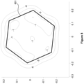
- FIG. 7 illustrates a contour plot of MBA directivity with respect to peak directivity in accordance with an implementation.
- the illustrated plot depicts performance of a seven element spot beam and a 5 m diameter reflector. It may be observed that, in the illustrated example, a beam width in the far-field, represented by two opposing edges of the hexagonal polygon 701, is about 0.2°.
- the gain-area product for the illustrated implementation has been found to be about 14,500, corresponding to approximately 35% efficiency.
- the rolloff at the edge of the hexagonal polygon 701 is about 4-4.5db.
- the 6 dB rolloff contour is approximately circular, denoting the effects of diffraction limits.
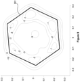
- Figure 8 illustrates a contour plot of MBA directivity with respect to peak directivity in accordance with another implementation.
- the illustrated plot depicts performance of a nineteen element spot beam and a reflector of about 9 meter diameter. It may be observed that the beam width in the far-field, represented by two opposing edges of the hexagonal polygon 801, is about 0.35°.
- the average directivity in the hexagonal polygon 801 is about 54 dB.
- the gain-area product for the illustrated implementation has been found to be over 25,000, corresponding to better than 61% efficiency.
- the rolloff at the edge of the hexagonal polygon 801 is about 1-2 db.
- the 6 dB rolloff contour is approximately hexagonal, denoting more precise beam forming. It may be observed that, because of the above-mentioned steep roll-off, nearly adjacent coverage areas (not illustrated) may each be configured at an identical combination of frequency sub-band and polarization, with negligible mutual interference.
- the frequency reuse scheme may be employed while avoiding use of a signal encoding scheme.
- Figure 9 illustrates a contour plot of MBA directivity with respect to peak directivity in accordance with a yet further implementation.
- the illustrated plot depicts performance of a 37 element spot beam and a reflector of about 9 meter diameter. It may be observed that the beam width in the far-field, represented by two opposing vertices of the hexagonal polygon 901, is about 0.48°.
- the average directivity in the hexagonal polygon 901 is 51 dBi.
- the gain-area product is about 24,000, corresponding to better than 58% efficiency.
- the rolloff at the edge of the hexagonal polygon 901 is about 4 db.
- the 6 dB rolloff contour is approximately hexagonal.
- FIG. 10 a contour plot of MBA directivity with respect to boresight peak directivity for a 37 helix element spot beam coverage area is illustrated.
- the contour plot assumes a reflector of about 3 meter diameter.
- the beam spacing in the far-field represented by two opposing edges of the hexagonal polygon 1001 is about 0.9°.
- the rolloff at the edge of the hexagonal polygon 1001 is about 4 db.
- the 6 dB rolloff contour is approximately hexagonal.
- An MBA system configured to form approximately 300 such beams can provide, full earth coverage.
Landscapes
- Physics & Mathematics (AREA)
- Engineering & Computer Science (AREA)
- Astronomy & Astrophysics (AREA)
- General Physics & Mathematics (AREA)
- Remote Sensing (AREA)
- Aviation & Aerospace Engineering (AREA)
- Electromagnetism (AREA)
- Aerials With Secondary Devices (AREA)
- Variable-Direction Aerials And Aerial Arrays (AREA)
- Details Of Aerials (AREA)
Claims (12)
- Mehrstrahlantennensystem für ein Raumfahrzeug, wobei das Mehrstrahlantennensystem Folgendes umfasst:einen Reflektor; undmehrere abstrahlende Speiseelemente (165), die als ein phasengesteuertes Array konfiguriert sind und den Reflektor beleuchten, die konfiguriert sind, um bei einer Frequenz in Betrieb zu sein, die eine charakteristische Wellenlänge (λ) aufweist, wobei die Speiseelemente konfiguriert sind, um in einem Fernfeld an dem Reflektor einen Satz zusammenhängender angrenzender Strahlen zu erzeugen;wobei jedes abstrahlende Speiseelement (165) mit einem jeweiligen Verstärkermodul (150) gekoppelt ist und nahe diesem angeordnet ist, wobei jedes abstrahlende Speiseelement konfiguriert ist, um ein jeweiliges Beamlet auszubilden; undwobei jedes abstrahlende Speiseelement (165) zusammen mit seinem jeweiligen Verstärkermodul (150) in einem dicht gepackten dreieckigen Gitter angeordnet ist,wobei jedes jeweilige Beamlet eine Beamlet-Breite in dem Fernfeld aufweist, wobei die Beamlet-Breite eine Funktion der charakteristischen Wellenlänge und eines Durchmessers des Reflektors ist;und wobei das Mehrstrahlantennensystem derart konfiguriert ist, dass die Beamlets einen Beamlet-Abstand in dem Fernfeld aufweisen;dadurch gekennzeichnet, dass die Beamlet-Breite in einem 20 GHz-Band ungefähr 0,1 Grad beträgt und der Beamlet-Abstand kleiner als die Beamlet-Breite ist; und wobei die Trennung zwischen benachbarten abstrahlenden Speiseelementen nicht größer als 2 λ ist.
- Mehrstrahlantennensystem nach Anspruch 1, wobei jedes der abstrahlenden Speiseelemente nur einem der zusammenhängenden angrenzenden Strahlen zugeordnet ist.
- Mehrstrahlantennensystem nach Anspruch 1 oder 2, wobei jeder Strahl aus mehreren zugeordneten Beamlets ausgebildet wird und jedes abstrahlende Speiseelement einem einzelnen der mehreren zugeordneten Beamlets zugeordnet ist.
- Mehrstrahlantennensystem nach einem der vorhergehenden Ansprüche, wobei jedes Verstärkermodul einen ersten Verstärker und einen zweiten Verstärker beinhaltet, wobei jeder Verstärker orthogonalen Polarisationen entspricht.
- Mehrstrahlantennensystem nach Anspruch 1, wobei der Beamlet-Abstand ungefähr 0,07 Grad beträgt.
- Mehrstrahlantennensystem nach einem der vorhergehenden Ansprüche, wobei für jeden Strahl in dem Satz zusammenhängender angrenzender Strahlen ein einzelner Träger betrieben wird.
- Mehrstrahlantennensystem nach einem der vorhergehenden Ansprüche, wobei für jeden Strahl in dem Satz zusammenhängender angrenzender Strahlen ein Satz von Verstärkern (650A, 650B) konfiguriert ist, um eine weiche Redundanz bereitzustellen.
- Mehrstrahlantennensystem nach einem der vorhergehenden Ansprüche, wobei jedes abstrahlende Speiseelement ein endgebranntes Element beinhaltet, wobei das endgebrannte Element als ein sprialförmiges, Yagi, Kreuzyagi, logarithmisch periodisches oder ein gestapeltes Patch-Antennenelement konfiguriert ist.
- Mehrstrahlantennensystem nach einem der vorhergehenden Ansprüche, wobei jedes Verstärkermodul wenigstens einen Hauptverstärker und wenigstens einen Hilfsverstärker beinhaltet, wobei der wenigstens eine Hauptverstärker und der wenigstens eine Hilfsverstärker in einer Doherty-Konfiguration eingerichtet sind.
- Raumfahrzeug, das ein Kommunikationsnutzlastteilsystem umfasst, wobei das Nutzlastteilsystem ein Mehrstrahlantennensystem nach Anspruch 1 beinhaltet.
- Raumfahrzeug nach Anspruch 10, wobei jedes der abstrahlenden Speiseelemente nur einem der zusammenhängenden angrenzenden Strahlen zugeordnet ist.
- Raumfahrzeug nach Anspruch 10 oder 11, wobei jeder Strahl aus mehreren zugeordneten Beamlets ausgebildet wird.
Applications Claiming Priority (2)
| Application Number | Priority Date | Filing Date | Title |
|---|---|---|---|
| US201662360840P | 2016-07-11 | 2016-07-11 | |
| US15/438,620 US10305195B2 (en) | 2016-07-11 | 2017-02-21 | Imaging array fed reflector |
Publications (2)
| Publication Number | Publication Date |
|---|---|
| EP3270463A1 EP3270463A1 (de) | 2018-01-17 |
| EP3270463B1 true EP3270463B1 (de) | 2022-02-16 |
Family
ID=59067559
Family Applications (1)
| Application Number | Title | Priority Date | Filing Date |
|---|---|---|---|
| EP17176140.6A Active EP3270463B1 (de) | 2016-07-11 | 2017-06-14 | Bildgebungsarray-gespeister reflektor |
Country Status (2)
| Country | Link |
|---|---|
| US (1) | US10305195B2 (de) |
| EP (1) | EP3270463B1 (de) |
Families Citing this family (5)
| Publication number | Priority date | Publication date | Assignee | Title |
|---|---|---|---|---|
| US9373896B2 (en) * | 2013-09-05 | 2016-06-21 | Viasat, Inc | True time delay compensation in wideband phased array fed reflector antenna systems |
| FR3067535B1 (fr) * | 2017-06-09 | 2023-03-03 | Airbus Defence & Space Sas | Satellite de telecommunications, procede de formation de faisceaux et procede de fabrication d’une charge utile de satellite |
| US10461409B1 (en) | 2017-12-04 | 2019-10-29 | Space Systems/Loral, Llc | Pointing system improvement with imaging array feeds |
| US10892796B1 (en) * | 2020-03-20 | 2021-01-12 | Rockwell Collins, Inc. | UWB spread spectrum power spatial combining antenna array |
| CA3280365A1 (en) * | 2024-08-02 | 2026-03-01 | Macdonald, Dettwiler And Associates Corporation | Integrated array element structure |
Citations (2)
| Publication number | Priority date | Publication date | Assignee | Title |
|---|---|---|---|---|
| US20030076274A1 (en) * | 2001-07-23 | 2003-04-24 | Phelan Harry Richard | Antenna arrays formed of spiral sub-array lattices |
| US20150061930A1 (en) * | 2013-09-05 | 2015-03-05 | Viasat, Inc. | True time delay compensation in wideband phased array fed reflector antenna systems |
Family Cites Families (14)
| Publication number | Priority date | Publication date | Assignee | Title |
|---|---|---|---|---|
| US3936835A (en) | 1974-03-26 | 1976-02-03 | Harris-Intertype Corporation | Directive disk feed system |
| US4236161A (en) | 1978-09-18 | 1980-11-25 | Bell Telephone Laboratories, Incorporated | Array feed for offset satellite antenna |
| US5936588A (en) | 1998-06-05 | 1999-08-10 | Rao; Sudhakar K. | Reconfigurable multiple beam satellite phased array antenna |
| US5936592A (en) | 1998-06-05 | 1999-08-10 | Ramanujam; Parthasarathy | Reconfigurable multiple beam satellite reflector antenna with an array feed |
| US6215452B1 (en) | 1999-01-15 | 2001-04-10 | Trw Inc. | Compact front-fed dual reflector antenna system for providing adjacent, high gain antenna beams |
| SE518207C2 (sv) | 1999-09-10 | 2002-09-10 | Ericsson Telefon Ab L M | Gles gruppantenn |
| US7034771B2 (en) * | 2003-09-10 | 2006-04-25 | The Boeing Company | Multi-beam and multi-band antenna system for communication satellites |
| US8354956B2 (en) * | 2006-01-13 | 2013-01-15 | Lockheed Martin Corporation | Space segment payload architecture for mobile satellite services (MSS) systems |
| FR2939568B1 (fr) | 2008-12-05 | 2010-12-17 | Thales Sa | Antenne a partage de sources et procede d'elaboration d'une antenne a partage de sources pour l'elaboration de multi-faisceaux |
| US8872719B2 (en) | 2009-11-09 | 2014-10-28 | Linear Signal, Inc. | Apparatus, system, and method for integrated modular phased array tile configuration |
| US8552917B2 (en) | 2010-04-28 | 2013-10-08 | The Boeing Company | Wide angle multibeams |
| US9153877B2 (en) | 2011-12-20 | 2015-10-06 | Space Systems/Loral, Llc | High efficiency multi-beam antenna |
| US10270524B2 (en) | 2014-04-15 | 2019-04-23 | Space Systems/Loral, Llc | Broadband satellite payload architecture |
| US10312995B2 (en) | 2014-12-11 | 2019-06-04 | Space Systems/Loral, Llc | Digital payload with variable high power amplifiers |
-
2017
- 2017-02-21 US US15/438,620 patent/US10305195B2/en active Active
- 2017-06-14 EP EP17176140.6A patent/EP3270463B1/de active Active
Patent Citations (2)
| Publication number | Priority date | Publication date | Assignee | Title |
|---|---|---|---|---|
| US20030076274A1 (en) * | 2001-07-23 | 2003-04-24 | Phelan Harry Richard | Antenna arrays formed of spiral sub-array lattices |
| US20150061930A1 (en) * | 2013-09-05 | 2015-03-05 | Viasat, Inc. | True time delay compensation in wideband phased array fed reflector antenna systems |
Also Published As
| Publication number | Publication date |
|---|---|
| EP3270463A1 (de) | 2018-01-17 |
| US10305195B2 (en) | 2019-05-28 |
| US20180013204A1 (en) | 2018-01-11 |
Similar Documents
| Publication | Publication Date | Title |
|---|---|---|
| US10116061B2 (en) | Beam steerable communication apparatus | |
| EP3618182B1 (de) | Dualpolarisierte fraktale antennenspeisearchitektur mit orthogonalen parallelplattenmoden | |
| US10305195B2 (en) | Imaging array fed reflector | |
| US9761937B2 (en) | Fragmented aperture for the Ka/K/Ku frequency bands | |
| EP3132494B1 (de) | Breitbandsatellitennutzlastarchitektur | |
| JP5613939B2 (ja) | マルチビームを生じるための、共用給電部を備えるアンテナ | |
| US20130321206A1 (en) | Interference rejections of satellite ground terminal with orthogonal beams | |
| US6307510B1 (en) | Patch dipole array antenna and associated methods | |
| EP3534459B1 (de) | Systeme und verfahren zur reduzierung der signalstrahlung in einer unerwünschten richtung | |
| CN115483539A (zh) | 用于多频带的电可操纵天线的平坦rf片 | |
| US11929552B2 (en) | Multi-channel communications antenna | |
| US20160301463A1 (en) | Broadband satellite payload architecture | |
| Huang et al. | A Wideband and Low Sidelobe Magnetoelectric Dipole Antenna Array With Embedded Resistors | |
| EP3859885B1 (de) | Fahrzeugantennenvorrichtung | |
| Qing et al. | A modular shared-aperture circularly polarized phased array antenna at k/ka-band on ltcc | |
| Yun et al. | Multibeam reflector antenna fed by few elements for Ka-band communication satellite | |
| US10566684B2 (en) | Amplifier integrated feed array with modularized feed elements and amplifiers | |
| JP3634047B2 (ja) | 移動体sng用グレーティングローブキャンセルアンテナ | |
| Abderrahmane et al. | An S band antenna system used for communication on earth observation microsatellite | |
| Kakaraparty et al. | High-gain, broadband radial elliptical-slot array antenna with side-lobe mitigation for low-cost satellite communication systems | |
| JPH08181540A (ja) | マルチビーム放射装置及びこれを用いたマルチビームアンテナ | |
| US20250264618A1 (en) | RF Lens Based Circularly Polarized Satellite Antenna Tracking System | |
| Egami et al. | An adaptive multiple-beam transmitter for satellite communications | |
| Gultepe | Ku-band Transmit/Receive All-Silicon Planar Phased Arrays for SATCOM and SOTM Terminals | |
| Kılık et al. | Design of a 132 GHz 1× 4 RHCP Microstrip Antenna Array with Rotman Lens for Inter-Satellite Links |
Legal Events
| Date | Code | Title | Description |
|---|---|---|---|
| PUAI | Public reference made under article 153(3) epc to a published international application that has entered the european phase |
Free format text: ORIGINAL CODE: 0009012 |
|
| STAA | Information on the status of an ep patent application or granted ep patent |
Free format text: STATUS: THE APPLICATION HAS BEEN PUBLISHED |
|
| AK | Designated contracting states |
Kind code of ref document: A1 Designated state(s): AL AT BE BG CH CY CZ DE DK EE ES FI FR GB GR HR HU IE IS IT LI LT LU LV MC MK MT NL NO PL PT RO RS SE SI SK SM TR |
|
| AX | Request for extension of the european patent |
Extension state: BA ME |
|
| STAA | Information on the status of an ep patent application or granted ep patent |
Free format text: STATUS: REQUEST FOR EXAMINATION WAS MADE |
|
| 17P | Request for examination filed |
Effective date: 20180717 |
|
| RBV | Designated contracting states (corrected) |
Designated state(s): AL AT BE BG CH CY CZ DE DK EE ES FI FR GB GR HR HU IE IS IT LI LT LU LV MC MK MT NL NO PL PT RO RS SE SI SK SM TR |
|
| STAA | Information on the status of an ep patent application or granted ep patent |
Free format text: STATUS: EXAMINATION IS IN PROGRESS |
|
| 17Q | First examination report despatched |
Effective date: 20201124 |
|
| REG | Reference to a national code |
Ref country code: DE Ref legal event code: R079 Ref document number: 602017053365 Country of ref document: DE Free format text: PREVIOUS MAIN CLASS: H01Q0025000000 Ipc: H01Q0021060000 |
|
| RIC1 | Information provided on ipc code assigned before grant |
Ipc: H01Q 21/06 20060101AFI20210604BHEP Ipc: H04B 7/204 20060101ALN20210604BHEP |
|
| RIC1 | Information provided on ipc code assigned before grant |
Ipc: H01Q 21/06 20060101AFI20210706BHEP Ipc: H01Q 1/28 20060101ALI20210706BHEP Ipc: H01Q 19/10 20060101ALI20210706BHEP Ipc: H01Q 19/17 20060101ALI20210706BHEP Ipc: H01Q 25/00 20060101ALI20210706BHEP Ipc: H04B 7/204 20060101ALN20210706BHEP |
|
| RIC1 | Information provided on ipc code assigned before grant |
Ipc: H01Q 21/06 20060101AFI20210712BHEP Ipc: H01Q 1/28 20060101ALI20210712BHEP Ipc: H01Q 19/10 20060101ALI20210712BHEP Ipc: H01Q 19/17 20060101ALI20210712BHEP Ipc: H01Q 25/00 20060101ALI20210712BHEP Ipc: H04B 7/204 20060101ALN20210712BHEP |
|
| GRAP | Despatch of communication of intention to grant a patent |
Free format text: ORIGINAL CODE: EPIDOSNIGR1 |
|
| STAA | Information on the status of an ep patent application or granted ep patent |
Free format text: STATUS: GRANT OF PATENT IS INTENDED |
|
| INTG | Intention to grant announced |
Effective date: 20210908 |
|
| GRAS | Grant fee paid |
Free format text: ORIGINAL CODE: EPIDOSNIGR3 |
|
| GRAA | (expected) grant |
Free format text: ORIGINAL CODE: 0009210 |
|
| STAA | Information on the status of an ep patent application or granted ep patent |
Free format text: STATUS: THE PATENT HAS BEEN GRANTED |
|
| AK | Designated contracting states |
Kind code of ref document: B1 Designated state(s): AL AT BE BG CH CY CZ DE DK EE ES FI FR GB GR HR HU IE IS IT LI LT LU LV MC MK MT NL NO PL PT RO RS SE SI SK SM TR |
|
| REG | Reference to a national code |
Ref country code: GB Ref legal event code: FG4D |
|
| REG | Reference to a national code |
Ref country code: CH Ref legal event code: EP |
|
| REG | Reference to a national code |
Ref country code: DE Ref legal event code: R096 Ref document number: 602017053365 Country of ref document: DE |
|
| REG | Reference to a national code |
Ref country code: AT Ref legal event code: REF Ref document number: 1469476 Country of ref document: AT Kind code of ref document: T Effective date: 20220315 |
|
| REG | Reference to a national code |
Ref country code: IE Ref legal event code: FG4D |
|
| REG | Reference to a national code |
Ref country code: LT Ref legal event code: MG9D |
|
| REG | Reference to a national code |
Ref country code: NL Ref legal event code: MP Effective date: 20220216 |
|
| REG | Reference to a national code |
Ref country code: AT Ref legal event code: MK05 Ref document number: 1469476 Country of ref document: AT Kind code of ref document: T Effective date: 20220216 |
|
| PG25 | Lapsed in a contracting state [announced via postgrant information from national office to epo] |
Ref country code: SE Free format text: LAPSE BECAUSE OF FAILURE TO SUBMIT A TRANSLATION OF THE DESCRIPTION OR TO PAY THE FEE WITHIN THE PRESCRIBED TIME-LIMIT Effective date: 20220216 Ref country code: RS Free format text: LAPSE BECAUSE OF FAILURE TO SUBMIT A TRANSLATION OF THE DESCRIPTION OR TO PAY THE FEE WITHIN THE PRESCRIBED TIME-LIMIT Effective date: 20220216 Ref country code: PT Free format text: LAPSE BECAUSE OF FAILURE TO SUBMIT A TRANSLATION OF THE DESCRIPTION OR TO PAY THE FEE WITHIN THE PRESCRIBED TIME-LIMIT Effective date: 20220616 Ref country code: NO Free format text: LAPSE BECAUSE OF FAILURE TO SUBMIT A TRANSLATION OF THE DESCRIPTION OR TO PAY THE FEE WITHIN THE PRESCRIBED TIME-LIMIT Effective date: 20220516 Ref country code: NL Free format text: LAPSE BECAUSE OF FAILURE TO SUBMIT A TRANSLATION OF THE DESCRIPTION OR TO PAY THE FEE WITHIN THE PRESCRIBED TIME-LIMIT Effective date: 20220216 Ref country code: LT Free format text: LAPSE BECAUSE OF FAILURE TO SUBMIT A TRANSLATION OF THE DESCRIPTION OR TO PAY THE FEE WITHIN THE PRESCRIBED TIME-LIMIT Effective date: 20220216 Ref country code: HR Free format text: LAPSE BECAUSE OF FAILURE TO SUBMIT A TRANSLATION OF THE DESCRIPTION OR TO PAY THE FEE WITHIN THE PRESCRIBED TIME-LIMIT Effective date: 20220216 Ref country code: ES Free format text: LAPSE BECAUSE OF FAILURE TO SUBMIT A TRANSLATION OF THE DESCRIPTION OR TO PAY THE FEE WITHIN THE PRESCRIBED TIME-LIMIT Effective date: 20220216 Ref country code: BG Free format text: LAPSE BECAUSE OF FAILURE TO SUBMIT A TRANSLATION OF THE DESCRIPTION OR TO PAY THE FEE WITHIN THE PRESCRIBED TIME-LIMIT Effective date: 20220516 |
|
| PG25 | Lapsed in a contracting state [announced via postgrant information from national office to epo] |
Ref country code: PL Free format text: LAPSE BECAUSE OF FAILURE TO SUBMIT A TRANSLATION OF THE DESCRIPTION OR TO PAY THE FEE WITHIN THE PRESCRIBED TIME-LIMIT Effective date: 20220216 Ref country code: LV Free format text: LAPSE BECAUSE OF FAILURE TO SUBMIT A TRANSLATION OF THE DESCRIPTION OR TO PAY THE FEE WITHIN THE PRESCRIBED TIME-LIMIT Effective date: 20220216 Ref country code: GR Free format text: LAPSE BECAUSE OF FAILURE TO SUBMIT A TRANSLATION OF THE DESCRIPTION OR TO PAY THE FEE WITHIN THE PRESCRIBED TIME-LIMIT Effective date: 20220517 Ref country code: FI Free format text: LAPSE BECAUSE OF FAILURE TO SUBMIT A TRANSLATION OF THE DESCRIPTION OR TO PAY THE FEE WITHIN THE PRESCRIBED TIME-LIMIT Effective date: 20220216 Ref country code: AT Free format text: LAPSE BECAUSE OF FAILURE TO SUBMIT A TRANSLATION OF THE DESCRIPTION OR TO PAY THE FEE WITHIN THE PRESCRIBED TIME-LIMIT Effective date: 20220216 |
|
| PG25 | Lapsed in a contracting state [announced via postgrant information from national office to epo] |
Ref country code: IS Free format text: LAPSE BECAUSE OF FAILURE TO SUBMIT A TRANSLATION OF THE DESCRIPTION OR TO PAY THE FEE WITHIN THE PRESCRIBED TIME-LIMIT Effective date: 20220617 |
|
| PG25 | Lapsed in a contracting state [announced via postgrant information from national office to epo] |
Ref country code: SM Free format text: LAPSE BECAUSE OF FAILURE TO SUBMIT A TRANSLATION OF THE DESCRIPTION OR TO PAY THE FEE WITHIN THE PRESCRIBED TIME-LIMIT Effective date: 20220216 Ref country code: SK Free format text: LAPSE BECAUSE OF FAILURE TO SUBMIT A TRANSLATION OF THE DESCRIPTION OR TO PAY THE FEE WITHIN THE PRESCRIBED TIME-LIMIT Effective date: 20220216 Ref country code: RO Free format text: LAPSE BECAUSE OF FAILURE TO SUBMIT A TRANSLATION OF THE DESCRIPTION OR TO PAY THE FEE WITHIN THE PRESCRIBED TIME-LIMIT Effective date: 20220216 Ref country code: EE Free format text: LAPSE BECAUSE OF FAILURE TO SUBMIT A TRANSLATION OF THE DESCRIPTION OR TO PAY THE FEE WITHIN THE PRESCRIBED TIME-LIMIT Effective date: 20220216 Ref country code: DK Free format text: LAPSE BECAUSE OF FAILURE TO SUBMIT A TRANSLATION OF THE DESCRIPTION OR TO PAY THE FEE WITHIN THE PRESCRIBED TIME-LIMIT Effective date: 20220216 Ref country code: CZ Free format text: LAPSE BECAUSE OF FAILURE TO SUBMIT A TRANSLATION OF THE DESCRIPTION OR TO PAY THE FEE WITHIN THE PRESCRIBED TIME-LIMIT Effective date: 20220216 |
|
| REG | Reference to a national code |
Ref country code: DE Ref legal event code: R097 Ref document number: 602017053365 Country of ref document: DE |
|
| PG25 | Lapsed in a contracting state [announced via postgrant information from national office to epo] |
Ref country code: AL Free format text: LAPSE BECAUSE OF FAILURE TO SUBMIT A TRANSLATION OF THE DESCRIPTION OR TO PAY THE FEE WITHIN THE PRESCRIBED TIME-LIMIT Effective date: 20220216 |
|
| PLBE | No opposition filed within time limit |
Free format text: ORIGINAL CODE: 0009261 |
|
| STAA | Information on the status of an ep patent application or granted ep patent |
Free format text: STATUS: NO OPPOSITION FILED WITHIN TIME LIMIT |
|
| REG | Reference to a national code |
Ref country code: DE Ref legal event code: R119 Ref document number: 602017053365 Country of ref document: DE |
|
| 26N | No opposition filed |
Effective date: 20221117 |
|
| PG25 | Lapsed in a contracting state [announced via postgrant information from national office to epo] |
Ref country code: MC Free format text: LAPSE BECAUSE OF FAILURE TO SUBMIT A TRANSLATION OF THE DESCRIPTION OR TO PAY THE FEE WITHIN THE PRESCRIBED TIME-LIMIT Effective date: 20220216 |
|
| REG | Reference to a national code |
Ref country code: CH Ref legal event code: PL |
|
| REG | Reference to a national code |
Ref country code: BE Ref legal event code: MM Effective date: 20220630 |
|
| PG25 | Lapsed in a contracting state [announced via postgrant information from national office to epo] |
Ref country code: SI Free format text: LAPSE BECAUSE OF FAILURE TO SUBMIT A TRANSLATION OF THE DESCRIPTION OR TO PAY THE FEE WITHIN THE PRESCRIBED TIME-LIMIT Effective date: 20220216 |
|
| GBPC | Gb: european patent ceased through non-payment of renewal fee |
Effective date: 20220614 |
|
| PG25 | Lapsed in a contracting state [announced via postgrant information from national office to epo] |
Ref country code: LU Free format text: LAPSE BECAUSE OF NON-PAYMENT OF DUE FEES Effective date: 20220614 Ref country code: LI Free format text: LAPSE BECAUSE OF NON-PAYMENT OF DUE FEES Effective date: 20220630 Ref country code: IE Free format text: LAPSE BECAUSE OF NON-PAYMENT OF DUE FEES Effective date: 20220614 Ref country code: CH Free format text: LAPSE BECAUSE OF NON-PAYMENT OF DUE FEES Effective date: 20220630 |
|
| PG25 | Lapsed in a contracting state [announced via postgrant information from national office to epo] |
Ref country code: GB Free format text: LAPSE BECAUSE OF NON-PAYMENT OF DUE FEES Effective date: 20220614 Ref country code: DE Free format text: LAPSE BECAUSE OF NON-PAYMENT OF DUE FEES Effective date: 20230103 Ref country code: BE Free format text: LAPSE BECAUSE OF NON-PAYMENT OF DUE FEES Effective date: 20220630 |
|
| P01 | Opt-out of the competence of the unified patent court (upc) registered |
Effective date: 20230528 |
|
| PG25 | Lapsed in a contracting state [announced via postgrant information from national office to epo] |
Ref country code: IT Free format text: LAPSE BECAUSE OF FAILURE TO SUBMIT A TRANSLATION OF THE DESCRIPTION OR TO PAY THE FEE WITHIN THE PRESCRIBED TIME-LIMIT Effective date: 20220216 |
|
| PG25 | Lapsed in a contracting state [announced via postgrant information from national office to epo] |
Ref country code: HU Free format text: LAPSE BECAUSE OF FAILURE TO SUBMIT A TRANSLATION OF THE DESCRIPTION OR TO PAY THE FEE WITHIN THE PRESCRIBED TIME-LIMIT; INVALID AB INITIO Effective date: 20170614 |
|
| PG25 | Lapsed in a contracting state [announced via postgrant information from national office to epo] |
Ref country code: MK Free format text: LAPSE BECAUSE OF FAILURE TO SUBMIT A TRANSLATION OF THE DESCRIPTION OR TO PAY THE FEE WITHIN THE PRESCRIBED TIME-LIMIT Effective date: 20220216 Ref country code: CY Free format text: LAPSE BECAUSE OF FAILURE TO SUBMIT A TRANSLATION OF THE DESCRIPTION OR TO PAY THE FEE WITHIN THE PRESCRIBED TIME-LIMIT Effective date: 20220216 |
|
| PG25 | Lapsed in a contracting state [announced via postgrant information from national office to epo] |
Ref country code: TR Free format text: LAPSE BECAUSE OF FAILURE TO SUBMIT A TRANSLATION OF THE DESCRIPTION OR TO PAY THE FEE WITHIN THE PRESCRIBED TIME-LIMIT Effective date: 20220216 |
|
| PG25 | Lapsed in a contracting state [announced via postgrant information from national office to epo] |
Ref country code: MT Free format text: LAPSE BECAUSE OF FAILURE TO SUBMIT A TRANSLATION OF THE DESCRIPTION OR TO PAY THE FEE WITHIN THE PRESCRIBED TIME-LIMIT Effective date: 20220216 |
|
| PGFP | Annual fee paid to national office [announced via postgrant information from national office to epo] |
Ref country code: FR Payment date: 20250401 Year of fee payment: 9 |