EP3271907B1 - Système de mesure de température comprenant un transpondeur électromagnétique et une antenne passive à changement d'impédance distincte - Google Patents
Système de mesure de température comprenant un transpondeur électromagnétique et une antenne passive à changement d'impédance distincte Download PDFInfo
- Publication number
- EP3271907B1 EP3271907B1 EP16765689.1A EP16765689A EP3271907B1 EP 3271907 B1 EP3271907 B1 EP 3271907B1 EP 16765689 A EP16765689 A EP 16765689A EP 3271907 B1 EP3271907 B1 EP 3271907B1
- Authority
- EP
- European Patent Office
- Prior art keywords
- antenna
- transponder
- temperature
- parasitic antenna
- sensor
- Prior art date
- Legal status (The legal status is an assumption and is not a legal conclusion. Google has not performed a legal analysis and makes no representation as to the accuracy of the status listed.)
- Active
Links
Images


Classifications
-
- H—ELECTRICITY
- H05—ELECTRIC TECHNIQUES NOT OTHERWISE PROVIDED FOR
- H05B—ELECTRIC HEATING; ELECTRIC LIGHT SOURCES NOT OTHERWISE PROVIDED FOR; CIRCUIT ARRANGEMENTS FOR ELECTRIC LIGHT SOURCES, IN GENERAL
- H05B6/00—Heating by electric, magnetic or electromagnetic fields
- H05B6/02—Induction heating
- H05B6/06—Control, e.g. of temperature, of power
- H05B6/062—Control, e.g. of temperature, of power for cooking plates or the like
-
- G—PHYSICS
- G01—MEASURING; TESTING
- G01K—MEASURING TEMPERATURE; MEASURING QUANTITY OF HEAT; THERMALLY-SENSITIVE ELEMENTS NOT OTHERWISE PROVIDED FOR
- G01K1/00—Details of thermometers not specially adapted for particular types of thermometer
- G01K1/02—Means for indicating or recording specially adapted for thermometers
- G01K1/024—Means for indicating or recording specially adapted for thermometers for remote indication
-
- G—PHYSICS
- G01—MEASURING; TESTING
- G01K—MEASURING TEMPERATURE; MEASURING QUANTITY OF HEAT; THERMALLY-SENSITIVE ELEMENTS NOT OTHERWISE PROVIDED FOR
- G01K7/00—Measuring temperature based on the use of electric or magnetic elements directly sensitive to heat ; Power supply therefor, e.g. using thermoelectric elements
- G01K7/36—Measuring temperature based on the use of electric or magnetic elements directly sensitive to heat ; Power supply therefor, e.g. using thermoelectric elements using magnetic elements, e.g. magnets, coils
-
- H—ELECTRICITY
- H05—ELECTRIC TECHNIQUES NOT OTHERWISE PROVIDED FOR
- H05B—ELECTRIC HEATING; ELECTRIC LIGHT SOURCES NOT OTHERWISE PROVIDED FOR; CIRCUIT ARRANGEMENTS FOR ELECTRIC LIGHT SOURCES, IN GENERAL
- H05B6/00—Heating by electric, magnetic or electromagnetic fields
- H05B6/02—Induction heating
- H05B6/10—Induction heating apparatus, other than furnaces, for specific applications
- H05B6/105—Induction heating apparatus, other than furnaces, for specific applications using a susceptor
-
- H—ELECTRICITY
- H05—ELECTRIC TECHNIQUES NOT OTHERWISE PROVIDED FOR
- H05B—ELECTRIC HEATING; ELECTRIC LIGHT SOURCES NOT OTHERWISE PROVIDED FOR; CIRCUIT ARRANGEMENTS FOR ELECTRIC LIGHT SOURCES, IN GENERAL
- H05B6/00—Heating by electric, magnetic or electromagnetic fields
- H05B6/02—Induction heating
- H05B6/10—Induction heating apparatus, other than furnaces, for specific applications
- H05B6/12—Cooking devices
- H05B6/1209—Cooking devices induction cooking plates or the like and devices to be used in combination with them
-
- H—ELECTRICITY
- H05—ELECTRIC TECHNIQUES NOT OTHERWISE PROVIDED FOR
- H05B—ELECTRIC HEATING; ELECTRIC LIGHT SOURCES NOT OTHERWISE PROVIDED FOR; CIRCUIT ARRANGEMENTS FOR ELECTRIC LIGHT SOURCES, IN GENERAL
- H05B2213/00—Aspects relating both to resistive heating and to induction heating, covered by H05B3/00 and H05B6/00
- H05B2213/06—Cook-top or cookware capable of communicating with each other
-
- H—ELECTRICITY
- H05—ELECTRIC TECHNIQUES NOT OTHERWISE PROVIDED FOR
- H05B—ELECTRIC HEATING; ELECTRIC LIGHT SOURCES NOT OTHERWISE PROVIDED FOR; CIRCUIT ARRANGEMENTS FOR ELECTRIC LIGHT SOURCES, IN GENERAL
- H05B2213/00—Aspects relating both to resistive heating and to induction heating, covered by H05B3/00 and H05B6/00
- H05B2213/07—Heating plates with temperature control means
Definitions
- the present invention is broadly concerned with temperature sensors and temperature measurement systems permitting wireless temperature measurement of various objects during heating or cooling thereof. More particularly, the invention is concerned with such sensor and systems, and especially those designed for heating of food servingware, such as food plate domes.
- the sensors include a transponder and a proximal parasitic antenna, the latter having a temperature-sensitive transducer operable to change the impedance value of the parasitic antenna when the object being temperature-sensed reaches a predetermined temperature for transducer operation.
- RFID Radio Frequency Identification
- the 169 patent describes Radio Frequency Identification (RFID) labels or tags physically connected to one or more thermal switches, where the thermal switch(es) are in contact with an object whose temperature is to be remotely measured. Interrogating electromagnetic signals are generated, which are received by the RFID tag, which in turn generates reply signals. However, when the object temperature reaches or exceeds a pre-set temperature, the thermal switch(es) disconnect the RFID antenna so that no reply signals are generated. This is interpreted by the system as a condition where the object has reached or exceeded the pre-set temperature.
- RFID Radio Frequency Identification
- the tag/switch combination is difficult to incorporate within an object whose temperature is to be measured.
- the physical connection between the tags and switches is inherently delicate, making use of fine connection wires and connectors soldered or affixed to the tag. As such, it is very difficult to injection mold such a tag/switch combination within an object.
- the connection between the switch and tag is short in length so as to facilitate manufacturing, the tag may be too close to the object to be measured to allow for good communication with the tag, owing to antenna de-tuning by the object, especially if the object is made from an electrically conducting material.
- the connection is lengthened so as to enhance communications by eliminating any adverse effects from the object, the difficulty of incorporation into the object increases.
- the fact that the tag is connected to the switch means that thermal energy from the object in contact with the switch will conduct or radiate to the tag, either through the connecting leads or simply by conduction through adjacent matter.
- the integrated circuitry of the tag may be destroyed or tag communication may be disrupted.
- US Patent No. 6,172,608 discloses an enhanced range transponder system including a transponder label electromagnetically coupled to a parasitic antenna, the latter being simultaneously electromagnetically coupled to the interrogator.
- the transponder system of the 608 patent is not designed to measure object temperatures, either at single or multiple temperature measurement locations on an object.
- DE 202009018612 U1 discloses a transponder device having a sensor element having a material, wherein a state of the sensor element changes in response to a physical or chemical action on the material.
- the present invention overcomes the problems outlined above and provides enhanced wireless temperature sensor systems usable with a wide variety of objects to the temperature-measured, and particularly food servingware.
- die invention provides wireless temperature sensors, temperature measurement systems including the sensors, and food servingware items, such as plate domes, which incorporate the temperature sensors.
- the invention eliminates the need for a physical or wired connection between labels or tags and temperature-sensitive switches typical of prior art sensor systems.
- the wireless temperature sensor of the invention is configured for attachment to an object in order to sense if the object reaches a preset temperature, said sensor comprising a transponder including a transponder antenna and a circuit operably coupled with the transponder antenna, the circuit operable to extract, energy from electromagnetic signals received by the transponder antenna, and to generate transponder reply signals containing reply information.
- the sensors further include a parasitic antenna having an impedance value and operable to be excited by electromagnetic signals including the transponder reply signals in order to generate parasitic antenna reply signals, which include the reply information.
- the transponder antenna and parasitic antenna are in proximity and are electromagnetically coupled by through a mutual induction path when the electromagnetic signals are received.
- the parasitic antenna includes a temperature-sensitive transducer for operative thermal contact with said object, said transducer operable to change the impedance value of the parasitic antenna if the object reaches said preset temperature, to thereby change a detectable parameter of the parasitic antenna reply signals, wherein the transponder and the temperature-sensitive transducer are thermally insulated from one another.
- the sensors of the invention are designed so that the relative positions of the transponder and parasitic antenna are fixed. This can be achieved by mounting these components on a substrate, such as a rigid insulating material commonly used for the production of printed electronic circuit boards (e.g., FR.-4). but could also be in the form of flexible materials, such as Kapton® or Mylar®.
- the chosen substrate material should be electrically insulating and capable of withstanding the temperatures to which the associated object will be subjected.
- the transponder and parasitic antenna can be separately mounted on or in the object to be temperature-measured; advantageously, these components are separated by thermal insulating materials. In either case, the temperature sensors of the invention can be easily integrated into the objects, even via injection molding.
- the transducer is selected from the group consisting of temperature-sensitive switches, electrically conductive traces formed of positive temperature coefficient ink, and combinations thereof.
- the parasitic antenna may also include one or more transducers, as desired.
- Complete temperature measurement systems preferably include the temperature sensors in combination with an interrogator operable to generate the necessary electronic signals received by the transponder and antenna.
- the most preferred is art RFID reader or reader/writer, which is mated with the corresponding RFID tag.
- the interrogator is strategically placed relative to the sensor to give the proper operational characteristics to the systems.
- domes to accordance with the invention typically include a dome body presenting a central section and a peripheral skirt depending from the central section.
- the central sections of the domes have an induction-heatable component and a wireless temperature sensor of the type previously described, which is actuated by means of an interrogator.
- the induction-heatable component may include a matrix having a plurality of induction-heatable layers sandwiched between alternating layers of heat-retentive material, which are well known in the art. Alternately, the component may be formed of ferromagnetic metal.
- the dome is placed in proximity to an appropriate interrogator, and is heated to a predetermined temperature, as described above.
- Heating of the dome is advantageously carried out using a specifically designed induction heater.
- the heater includes an upstanding cylindrical housing having a circular sidewall and a top wall, and a work coil within the cylindrical housing.
- the work, coil is operable, with the usual components of an induction heater such as an inverter and control circuitry, to generate an alternating magnetic field, which heats the dome's induction-heatable component.
- the induction heater housing is dimensioned so that the central section of the dome can be placed directly on the top wall of the housing, with the depending skin preventing any substantial lateral movement of the dome.
- the work coil of the heater is directly below the induction-heatable component of the dome, thereby assuring rapid heating of the dome.
- the housing also includes the system interrogator in the form of an RFID reader or reader/writer, as well as at least one upstanding interrogator antenna. Use of two or more such antennas assures that the dome will be heated notwithstanding the rotational position of the dome on the housing.
- Fig. 1 an exemplary temperature measurement system 20 is illustrated, which broadly includes a temperature sensor 22 and an interrogator 24.
- the sensor 22 is designed to be placed in effective thermal contact with an object whose temperature is to be sensed, whereas the interrogator 24 is a separate component in proximity to the sensor 22.
- the preferred sensor 22 includes a transponder, here in the form of RFID tag 26, advantageously a UHF Tagsys AK5, which has the ability to be read and written, with 160 reprogrammable bits and 96 identification bits.
- the tag 26 has an antenna 28 of self-inductance L3 and a microcircuit 30 (labeled LM) coupled with antenna 28 and operable to extract energy from the antenna and to generate and convey a reply signal to the antenna 28, or alternately to another antenna (not shown).
- the sensor 22 has a separate parasitic antenna 32 having a characteristic impedance value, a self-inductance L2, a thermal (e.g., bi-metallic) switch 34 (labeled SWI), and a turning capacitor 36 (labeled C1).
- the sensor components 26 and 32 are preferably mounted upon a substrate 38, such as a circuit board or the like, with a fixed distance D3 between these components.
- the parasitic antenna 32 is placed in thermal contact with the object to be temperature-sensed.
- the interrogator 24 includes an antenna 40 having self-inductance L1, operably coupled with a transmitter/receiver 42.
- the interrogator 24 is operable to successively interrogate sensor 22 during operation of the system 20 and to decode reply signals from sensor 22.
- the interrogator 24 is placed at a reading distance RD relative to the sensor 22.
- the system 20 uses electromagnetic communications in which the interrogator 24 containing a transmitter/receiver 42 generates electromagnetic signals which are transmitted via interrogator antenna 40 to RFID tag 26 containing antenna 28.
- the RFID antenna 2 8 receives a portion of the transmitted energy from antenna 40 and through a rectifier forming a part of microcircuit 30, generates DC power which is used for operation of a reply generation circuit, connected to the antenna 28. The result is that information-bearing electromagnetic reply signals are transmitted from tag 26 back to the receiver of the interrogator 24.
- One path of information transfer between interrogator 24 and tag 26 is the electromagnetic coupling path represented by mutual inductance M1 of Fig. 1 .
- the antenna 42 of interrogator 40 and antenna 28 of tag 26 take the form of loops of self-inductance L1 and L3.
- the principal form of direct coupling between such inductive loops is provided by reactive energy storage fields surrounding these antennas and is expressed in terms of the mutual inductance M1, between these loops.
- the interrogator antenna 40 excites the tag antenna 28 over an electromagnetic coupling path represented by the mutual inductance M1.
- the microcircuit 30 extracts energy from the excited tag antenna 28, and generates tag reply signals (or more generally, transponder reply signals), and conveys such tag reply signals to tag antenna 28 or perhaps to some separate label antenna not shown.
- the tag reply signals excite the interrogator's antenna 40 via the same electromagnetic coupling path M1.
- a second path of information transfer between interrogator 24 and tag 26 is illustrated.
- This second path comprises the individual electromagnetic coupling paths between parasitic antenna 32 and both the interrogator 24 and tag 26.
- an electromagnetic coupling path represented by the mutual inductance M2 couples parasitic antenna 32 having self-inductance L2 tuned by capacitor 36, with interrogator antenna 40 having self-inductance L1.
- the current which circulates in the parasitic antenna 32 also excites tag antenna 28 over an electromagnetic coupling path represented by mutual inductance M3 between parasitic antenna 32 and tag 26 having self-inductance L3.
- Fig. 1 depicts one method of changing the parasitic antenna impedance, by employing a thermal switch 34 along the conducting path of the parasitic antenna 32. When the thermal switch 34 is closed, the electromagnetic coupling paths shown by M2 and M3 are strong. Thus, the information from the tag reply signals, conveyed via the parasitic antenna reply signals, is received by the interrogator antenna 40.
- the maximum reading distance (the maximum distance between interrogator antenna 40 and temperature sensor 22 over which the information contained in the tag reply signals can be repeatedly received by interrogator antenna 40 and successfully decoded) is large value A.
- the temperature of thermal switch 34 or that portion of an object in thermal contact with it
- the switch will open and remain open. In this state, the impedance of the parasitic antenna 32 is greatly changed and the electromagnetic coupling paths M2 and M3 are severely reduced in strength. As such, the parasitic antenna reply signals may be no longer received at the distance A between interrogator 24 and temperature sensor 22.
- the tag reply signals may be received at a greater reading distance via electromagnetic coupling path M1 than the corresponding information received via paths M2 and M3.
- the maximum reading distance with the thermal switch 34 open will be a fraction of value A. If the distance RD has not changed during the temperature measurements (interrogations looking for reply signals), the sudden loss of reply signal after the thermal switch 34 opens is discerned by the interrogator's logic as a thermal switch temperature above or below its pre-set switching temperature.
- the senor 22 is operatively coupled with an object to be temperature-sensed, typically by application of the substrate 38 to the object so that switch 34 is in thermal contact with the object.
- the tag 26 and parasitic antenna 32 may be separated, so long as the distance therebetween permits effective electromagnetic communication. In all preferred forms of use, however, the distance between the tag 26 and antenna 38 is fixed during use, as is the distance between the interrogator 24 and the sensor 22.
- the switch 34 of sensor 22 is designed to actuate when a predetermined object temperature is sensed, for example, during heating of the object.
- the strengths of the electromagnetic couplings represented by M2 and M3 are strong and substantially constant so that the reply signals received by antenna 40 over paths M2 and M3 are of sufficient magnitude to be decoded by interrogator 24.
- the switch 34 operates (typically by opening) to greatly increase the impedance value of parasitic antenna 32. This in turn greatly reduces the strengths and magnitudes of the electromagnetic coupling paths M2 and M3.
- the reply signals from the sensor 22 may no longer be received by the interrogator 24, or are of greatly reduced magnitude, which is interpreted by the interrogator as a condition where the object has reached or is above the predetermined temperature.
- the switch 34 serves as a temperature-sensitive transducer operable to selectively change the impedance value of the parasitic antenna 32.
- the function of temperature sensor 22 is maximized when, the relative positions of the tag 26 and parasitic antenna 32 are fixed during temperature measurements. If this fixed relative relationship is maintained, then the distance between the antenna 40 of interrogator 24 and parasitic antenna 32 can be selected such that the interrogator will successfully receive the reply signal information from sensor 22 via the parasitic antenna reply signals when the object is below the pre-set temperature, but will not successfully receive the parasitic antenna reply signals when the object is at or above the pre-set temperature. Referring to Fig. 1 , if the parasitic antenna-RFID tag distance is D3, and the relative orientations of the parasitic antenna 32 and tag 26 are fixed, the maximum reading distance is the distance A.
- the interrogator 24 will successfully receive tag reply signal information when the object is below the pre-set temperature.
- the antenna 40 of interrogator 24 will no longer receive the tag reply signal information via the parasitic reply signal (or from the tag reply signal itself via the path represented by M1).
- maximum reading distance upon this impedance value change will be reduced by a factor B to a value A/B, which is typically in the range of about 5-10.
- tag reply signal information will be successfully received when the object, and thereby parasitic antenna 32, is below the pre-set temperature, and will not be received when a least a portion of the antenna 32 is at or above the pre-set temperature.
- the interrogator 24 is programmed to deduce the following: During the course of a continual interrogation of sensor 22, so long as parasitic reply signals are received from sensor 22, the object is below the pre-set temperature, whereas unsuccessful receipt of label signals means that at least some portion of the object in thermal contact the antenna 32 is at or above the pre-set temperature.
- FIG. 2 illustrates another embodiment of the invention in the form of a temperature-measuring system 44.
- the system 44 is identical with the system 20, save for the fact that the parasitic antenna 32 includes a pair of thermal switches 34 and 34a (labeled SW1 and SW2, respectively). Accordingly, the components of system 44 identical with those of system 20 have been labeled with identical reference numerals.
- the thermal switches 34, 34a may be set to open or close upon a predetermined temperature change of the sensed object. Inasmuch as the switches 34, 34a are designed to be in thermal contact with the object, it is possible that the body is not isothermal and thus the switches could be set at different predetermined temperatures. Thus, the purpose of the system 44 is to determine when at least one of two critical regions of the object reach a pre-set temperature for the region. Of course, more than two thermal switches may also be used. Once the first of multiple thermal switches opens at its predetermined temperature, the reply signal from the tag 26 would no longer be received by interrogator 24, and the logic of the interrogator would deduce that at least one of the thermal switches had reached its predetermined temperature.
- the sensor 46 includes a parasitic antenna 48 and a separate RFID tag 50, both mounted on a substrate 52.
- the antenna 48 includes elements 54, 56, 58, and 60.
- a thermal switch 62 interconnects the ends of elements 56 and 60, whereas element 54 is electrically connected with element 60 and element 58 is electrically connected with element 56.
- the switch 62 has a pre-set switching temperature which is chosen to achieve a desired regulation temperature.
- the elements 54-60 are electrically conducting paths, preferably formed of lengths of shielded copper wire of 26 gauge, and form a staggered pattern with the switch 62 at the approximate center of the pattern.
- the lengths of the elements 54-60 can be adjusted to achieve the desired strength of electromagnetic coupling with the antenna of RFID tag 50, such coupling being represented by the mutual inductance M3 of Fig. 1 .
- the electrical resistance across these elements from end to end is near 1 Ohm.
- the switch 62 operates when the sensed object reaches the preset temperature of the switch, the resistance rises to the mega Ohm range and remains there at temperatures above the pre-set temperature.
- the antenna 48 thus has a much larger impedance value at or above the predetermined temperature, as compared with the antenna 32 of Fig. 1 , so that the coupling paths M2 and M3 are considerably weaker upon operation of switch 62. This results in a reduction in the maximum reading distance for the sensor 46.
- FIG 4 illustrates an alternative temperature sensor 64 having multiple sensing locations.
- the individual components of sensor 64 are similar to those of sensor 46, and thus like reference numerals are used.
- the sensor 64 includes RFID tag 50 and parasitic antenna 48a having sensor elements 54, 56, 58, and 60, the latter electrically connected at central point 66.
- the elements 54-60 are of the same material and construction as those of Fig. 3 , and the combined length from end-to end of each leg of the resultant X shape is chosen, along with the fixed relative position of RFID tag 50 to achieve desired strength electromagnetic coupling paths M2 and M3 of Fig. 2 .
- each of the four switches there are four temperature-sensing locations, each being a different location on the object being temperature-sensed, and each in contact with a respective bi-metallic thermal switch 68, 70, 72, and 74.
- the predetermined temperatures of each of the four switches may be identical or they may be different from each other.
- the electrical resistance from the end of element 54 to element 58 is near one Ohm when the total length of these elements is 15cm. This resistance rises into the mega Ohms range at the predetermined temperatures of switch 68 and 72 due to the open circuit that occurs when one or more of these thermal switches opens and remains open.
- This much larger parasitic antenna impedance at, and at or above one or more predetermined switch temperatures causes the electromagnetic coupling paths M2 and M3 to be vastly weaker, resulting in a reduction in the maximum reading distance for the sensor 64.
- Figs. 5A and 5B The differential in maximum reading distances between the switch states (e.g., switch-closed and switch-open positions) in the systems of the invention is illustrated in Figs. 5A and 5B .
- a system employing interrogator 24 and sensor 46 is depicted in these figures, with the switch 62 being closed in Fig. 5A .
- the maximum reading distance RD is indicated by the distance arrow and is denominated as distance A, as previously discussed in connection with Fig. 1 .
- the switch 62 opens as a result of the sensed object reaching the predetermined temperature for the switch, the maximum reading distance RD is substantially reduced, by a denominator factor B, resulting from the very significant change in impedance for the antenna 48 incident to switch opening.
- FIG. 6 Another type of parasitic antenna 76 is illustrated in Fig. 6 .
- This antenna includes electrically connected conductive traces 78, 80, 82, and 84 mounted on a substrate 86 in an X-shaped pattern. These traces are formed of low resistivity conducting material, such as silver or copper. Preferably, the traces 78-84 are deposited or printed on substrate 86 using a silver ink, such as EC 1010 from Loctite. Each trace also includes a central section 78a, 80a, 82a, and 84a, respectively, which is electrically connected to the associated trace, and is formed using positive temperature coefficient ink (ECI 8001 from Loctite), likewise deposited or printed onto the substrate.
- ECI 8001 positive temperature coefficient ink
- each section 78a-84a increases in a stepwise fashion from approximately 10 Ohms to 80 Ohms at a pre-set temperature.
- the resistance as measured from the end of trace 78 to the end of segment 82 (and likewise from the end of segment 80 to the end of segment 84) is approximately 20 Ohms at a predetermined temperature, but rises to 160 Ohms at a temperature above the predetermined temperature. Therefore, when at least one of the sections 78a-84a senses the predetermined operational temperature, there is a substantial rise in electrical resistance which correspondingly increases the impedance value of antenna 76, leading to a significant reduction in the electromagnetic coupling paths M2 and M3. It will be appreciated that this embodiment makes use of a different type of temperature-sensitive transducer, namely the ink sections 78a-84a.
- the temperature measurement systems of the invention have wide applicability and can be used in a variety of contexts.
- One such use is with food servingware domes, which can be placed over a food-bearing plate in order to maintain the temperature of the food.
- Such domes are commonly used in institutional food situations, such as in hospitals or banquet rooms.
- FIGs. 7 and 8 illustrate such a servingware dome 88.
- the dome 88 has a central section 90 with a peripheral, outwardly and downwardly extending skirt section 92 thereby defining a central concavity 94.
- the bottom edge 96 of skirt section 92 is designed to rest upon or encircle a food-bearing plate (not shown).
- the section 90 and skirt 92 are formed within a polymeric shell 98 including an inner shell layer 100 and an outer shell layer 102.
- a central handle 104 extends upwardly from outer shell layer 102, as shown.
- the dome has an induction-heatable laminated matrix plate 106 in direct thermal contact with inner shell layer 100.
- This matrix plate 106 is preferably formed of material described in US Patent No. 6,657,170 , entitled “Heat Retentive Inductive Heatable Laminated Matrix,".
- the matrix plate 106 comprises a plurality of induction-heatable layers sandwiched between alternating layers of heat retentive material.
- the induction-heatable layers are formed of graphite
- the heat-retentive layers are formed of solid-to-solid phase change material, such as radiation cross-linked polyethylene.
- use may be made of a metal plate formed of ferromagnetic materials, in lieu of or in addition to the matrix plate 106.
- An RFID tag 108 is located directly beneath the outer shell layer 102 below handle 104, and is adhered thereto by silicon adhesive.
- the tag 108 is preferably the previously described Tagsys AK5.
- a parasitic antenna 76 ( Fig. 6 ) is positioned in direct contact with the opper surface of matrix plate 106, so that the sections 78a-84a are thermally coupled with the plate 106.
- a layer 110 of insulation is positioned over the antenna 76 and is preferably formed of fibrous aerogel insulation material, such as Pyrogel® XT-E produced by Aspen Aerogel, but may be formed of any other high temperature insulative material.
- Insulative material 112 fills the remainder of the dome structure, and is preferably a high temperature injectable foam, such as urethane.
- Figure 8 illustrates another dome embodiment 114 making use of the sensor 46 of Fig. 3 .
- the sensor 46 is in contact with insulative layer 110 and is sandwiched between the layer 110 and the induction-beatable matrix plate 106 (not shown in Fig. 8 ), so that the switch 62 is in thermal contact with the matrix plate 106.
- the dome 88 or 114 is heated prior to use thereof, by means of an induction heating apparatus 116 illustrated in Figs. 9-11 . As illustrated, the dome 88 is positioned atop the apparatus 116 for heating, and is removed for use when the induction-heatable matrix plate 106 reaches a predetermined temperature.
- the apparatus 116 includes an induction heater 118 and its associated work coil 120, preferably of the type described in US Patent No. 6,320,1 69 .
- the heater 118 has a rectifier 122, inverter 124, an abnormal load detection system 126, and control microprocessor 128.
- the heater components receive power from an external power source 130.
- the heater 118 is located within an upright cylindrical housing 132 with work coil 120 adjacent the top wall 134 of the housing. This allows the dome 114 to be located within the central section 90 thereof resting on the wall 134, and with skirt section 92 positioned about the housing 132.
- the housing 132 includes a laterally projecting section 136 and an upstanding antenna section 138.
- An interrogator 24, here in the form of an RFID reader 139 is located with housing section 136 and is electrically connected with microprocessor 128 via lead 140.
- the RFID reader 139 is preferably a ThingMagic Micro LTE Reader having two antenna ports and capable of transmitting at up to +30 dBm.
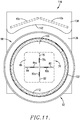
- the interrogator/RFID antenna 40 preferably includes two separate antennas 40a and 40b ( Fig. 11 ) located within the antenna section 138 and operably coupled with the RFID reader 139.
- the upright antenna section 138 has an inner face section 142 proximal to housing 132 formed of non-conducting material, such as a synthetic resin polymer or ceramic, so as to not affect the RF transmissions between the antennas 40a, 40b and the antenna 76 and RFID tag 108. Also, the mid-plane 144 of the antennas 40a and 40b should be on the same level or higher than the plane of RFID tag 108.
- the distance B between the center of the temperature-sensing structure of dome 90 (comprising both the RFID tag 108 and antenna 76) and the vertical center line of the antennas 40a and 40b should be less than the maximum reading distance A illustrated in Fig. 5A .
- the distance B is set at 0.75 x A, where A can be adjusted by the output power of the RFID reader 139. This is because the physical parameters affecting the mutual inductances M1, M2, and M3 are set by the fixed relative positions of the RFID tag 108 and parasitic antenna 76, as well as the fixed position of these components relative to the antennas 40a, 40b.
- Figure 10 illustrates a dome 88 properly positioned atop induction heater 118 for heating of the dome.
- Such proper positioning is achieved by two complementary aspects of the design of the induction heating apparatus 116.
- the mechanical fit of the dome 88 over the cylindrical housing 132 properly centers the dome. This is important because, should the dome 88 be placed off-center, the induction-beatable plate 106 would be at a greater average distance from work coil 120 than is shown in Fig. 10 . This greater average distance would cause the coupling between the work coil 120 and the matrix plate 106 to be lower than is required for the abnormal load detection system 126 to allow for continuous production of an alternating magnetic field by the apparatus 116.
- control microprocessor 128 will not allow continuous production of the alternating magnetic field unless the mid-plane 144 of the antennas 40a, 40b is above the plane of RFID tag 108, and the geometric center of the dome temperature sensor is less than the maximum reading distance A.
- the induction heating may commence.
- the microprocessor 128 will need to satisfy two conditions before it will permit continuous production of an alternating magnetic field to begin induction heating. It will first need to determine that the load provided by the dome is within the allowable load conditions for the abnormal load detection system 126. Second, it will need to determine that a valid reply signal from the RFID tag 108 has been received by RFID reader 139. The transmission and receipt of a signal to/from the tag 108 is preferably done prior to any induction work coil-produced magnetic field used to detect a load present on the apparatus 116.
- the induction heater When the two microprocessor conditions are met, the induction heater will produce a continuous alternating magnetic field for a pre-set duration to begin heating the dome 88 by virtue of the induction heating of matrix plate 106. After this pre-set duration is complete, the induction heater's microprocessor will cause the current flowing through the induction heater's work coil 120 to temporarily cease, during which time it will cause the RFID Reader 139 to transmit to the RFID tag 108. If all portions of the dome's induction-heatable matrix plate 106 are at a lower temperature than any of the parasitic antenna's PTC sections 78a-84a pre-set temperatures, then the RFID Reader 139 will receive reply signals. In this case, the maximum read range of the temperature measurement system of this invention will be the value A.
- the pre-set duration time is preferably two (2) seconds and the "off time" for RFID transmissions is preferably 50 milliseconds.
- the impedance of the parasitic antenna 76 will drastically increase and will cause the inductive coupling paths represented by M2 and M3 of Fig. 1 to become much weaker.
- the combined path represented by the combination of M2 and M3 may become weaker than the inductive coupling path represented by M1 of Fig. 1 .
- the weakened inductive coupling paths at this high temperature of the inductive heatable matrix plate 106 (and thus parasitic antenna 76) will reduce the maximum reading distance to a value C, as shown in Fig. 10 .
- the reader 139 will not receive reply signals of the same magnitude as before (or will not receive any signals whatsoever), and this will be interpreted as a condition where the plate 106 of dome 88 has reached or exceeds one of the pre-set temperatures of antenna 76. Therefore, the microprocessor 128 will stop the generation of a continuous magnetic field from work coil 120.
- the temperature sensor of the dome 88 it is preferable to design the temperature sensor of the dome 88 to make C equal a value of A/5. This will ensure that, during the next "off time" the RFID Reader 139 will not receive a reply response from the RFID tag 108. In such a case, one of the two necessary conditions for allowing a continuous production of magnetic field will not be achieved and the induction heater will not produce a continuous magnetic field. Instead, it will periodically continue to search for a reply signal from the RFID tag 108. No heating of the dome will occur during this time.
- the induction-heatable matrix plate 106 will fell in temperature such that the impedance of the parasitic antenna 76 changes back to the below-pre-set temperature value, such that the coupling path represented by M2 and M3 is strong enough such that the maximum reading range is again A.
- the induction heating of the dome will resume until the pre-set temperature is again exceeded. In this way the temperature of the induction-heatable element of the dome can be regulated about the pre-set temperature.
- apparatus 116 has been described in connection with the dome 88 having the separate RFID tag 108 and parasitic antenna 76, different types of transducers may be used, such as the thermal switch transducer 62 of Fig. 3 . Also, the induction heater's magnetic field may not need to be interrupted during RFID tag communications.
Landscapes
- Physics & Mathematics (AREA)
- Electromagnetism (AREA)
- General Physics & Mathematics (AREA)
- Measuring Temperature Or Quantity Of Heat (AREA)
- Arrangements For Transmission Of Measured Signals (AREA)
- Induction Heating Cooking Devices (AREA)
- Near-Field Transmission Systems (AREA)
Claims (14)
- Capteur de température sans fil (22) conçu pour être fixé à un objet afin de détecter si l'objet atteint une température prédéfinie, ledit capteur (22) comprenant :un transpondeur (26) comprenant une antenne à transpondeur (28) et un circuit (30) couplé de manière opérationnelle à l'antenne à transpondeur (28), ledit circuit (30) pouvant fonctionner pour extraire de l'énergie des signaux électromagnétiques reçus par ladite antenne à transpondeur (28), et pour générer des signaux de réponse de transpondeur contenant des informations de réponse ; etune antenne passive (32) ayant une valeur d'impédance et pouvant être excitée par lesdits signaux de réponse de transpondeur (26) afin de générer des signaux de réponse d'antenne passive contenant lesdites informations de réponse,ladite antenne à transpondeur (28) et ladite antenne passive (32) étant à proximité et couplées électromagnétiquement à travers un chemin d'induction mutuel lorsque lesdits signaux électromagnétiques sont reçus,caractérisé en ce que ladite antenne passive (32) comprend un transducteur sensible à la température (34) pour un contact thermique opérationnel avec ledit objet, ledit transducteur (34) pouvant fonctionner pour changer la valeur d'impédance de l'antenne passive (32) si ledit objet atteint ladite température prédéfinie, pour ainsi modifier un paramètre détectable desdits signaux de réponse d'antenne passive, dans lequelle transpondeur (26) et le transducteur sensible à la température (34) sont isolés thermiquement l'un de l'autre.
- Capteur selon la revendication 1, ledit transducteur (34) étant sélectionné dans le groupe composé d'un interrupteur sensible à la température, d'une trace électriquement conductrice formée d'encre à coefficient de température positif et de leurs combinaisons.
- Capteur selon la revendication 1, ladite antenne passive (32) comprenant une pluralité de transducteurs sensibles à la température (34, 34a), chacun pouvant fonctionner pour changer la valeur d'impédance de l'antenne passive (32) au niveau de différentes températures prédéfinies, respectivement.
- Capteur selon la revendication 1, lesdits signaux de réponse d'antenne passive ayant une amplitude liée à la valeur d'impédance de l'antenne passive (32), ledit paramètre détectable comprenant l'amplitude desdits signaux de réponse d'antenne passive.
- Capteur selon la revendication 1, ledit transpondeur (26) et ladite antenne passive (32) étant montés sur un substrat commun (38).
- Capteur selon la revendication 5, ledit transpondeur (26) et ladite antenne passive (32) étant montés séparément sur ledit substrat (38).
- Capteur selon la revendication 1, ledit transpondeur (26) étant isolé thermiquement dudit objet.
- Capteur selon la revendication 1, ladite antenne à transpondeur (28) et ladite antenne passive (32) étant couplées par inductance mutuelle (M3).
- Capteur selon la revendication 1, à la fois ladite antenne à transpondeur (28) et ladite antenne passive (32) pouvant fonctionner pour recevoir des signaux électromagnétiques d'interrogation.
- Système de mesure de température (20) pouvant fonctionner pour détecter si un objet atteint une température prédéfinie, comprenant le capteur de température sans fil (22) selon les revendications 1 à 9, en combinaison avec un interrogateur (24) pouvant fonctionner pour générer lesdits signaux électromagnétiques reçus par ladite antenne à transpondeur (28).
- Procédé permettant de détecter si un objet atteint une température prédéfinie, comprenant les étapes de fixation opérationnelle du capteur de température sans fil (22) selon les revendications 1 à 9 audit objet avec ledit transducteur sensible à la température (34) en contact thermique avec ledit objet, et l'utilisation d'un interrogateur (24) pour générer des signaux électromagnétiques reçus par l'antenne à transpondeur (28).
- Dôme chauffant pour vaisselle de service (88 ; 114), comprenant :un corps de dôme présentant une section centrale (90) et une jupe périphérique (92) dépendant de ladite section centrale (90), ladite section centrale (90) ayant un composant pouvant être chauffé par induction (106) et un capteur de température sans fil (46), ledit capteur de température sans fil comprenant;un transpondeur (108) comprenant une antenne à transpondeur et un circuit couplé de manière opérationnelle à l'antenne à transpondeur, ledit circuit pouvant fonctionner pour extraire de l'énergie des signaux électromagnétiques reçus par ladite antenne à transpondeur, et pour générer des signaux de réponse de transpondeur contenant des informations de réponse ; etune antenne passive (76) ayant une valeur d'impédance et pouvant être excitée par lesdits signaux de réponse de transpondeur afin de générer des signaux de réponse d'antenne passive contenant lesdites informations de réponse,ladite antenne à transpondeur et ladite antenne passive (76) étant à proximité et couplées électromagnétiquement à travers un chemin d'induction mutuel lorsque lesdits signaux électromagnétiques sont reçus,caractérisé en ce que ladite antenne passive (76) comprend un transducteur sensible à la température pouvant fonctionner pour changer la valeur d'impédance de l'antenne passive (76) si ledit composant atteint une température prédéterminée, pour ainsi changer un paramètre détectable desdits signaux de réponse d'antenne passive, ledit transducteur sensible à la température de ladite antenne passive (76) étant couplé thermiquement audit composant pouvant être chauffé par induction (106) afin de détecter la température du composant (106), et le transpondeur (108) et le transducteur sensible à la température sont thermiquement isolés l'un de l'autre.
- Dôme chauffant pour vaisselle de service (88 ; 114) selon la revendication 12, dans lequel ledit composant pouvant être chauffé par induction (106) comprend une matrice ayant une pluralité de couches pouvant être chauffées par induction intercalées entre des couches alternées de matériau retenant la chaleur.
- Dôme chauffant pour vaisselle de service (88 ; 114) selon la revendication 12 ou la revendication 13, dans lequel une distance entre ledit transpondeur (108) et ladite antenne passive (76) est fixe.
Applications Claiming Priority (3)
| Application Number | Priority Date | Filing Date | Title |
|---|---|---|---|
| US201562134246P | 2015-03-17 | 2015-03-17 | |
| US15/070,964 US10225890B2 (en) | 2015-03-17 | 2016-03-15 | Temperature measurement system employing an electromagnetic transponder and separate impedance-changing parasitic antenna |
| PCT/US2016/022706 WO2016149413A1 (fr) | 2015-03-17 | 2016-03-16 | Système de mesure de température comprenant un transpondeur électromagnétique et une antenne passive à changement d'impédance distincte |
Publications (3)
| Publication Number | Publication Date |
|---|---|
| EP3271907A1 EP3271907A1 (fr) | 2018-01-24 |
| EP3271907A4 EP3271907A4 (fr) | 2018-10-17 |
| EP3271907B1 true EP3271907B1 (fr) | 2020-06-03 |
Family
ID=56920003
Family Applications (1)
| Application Number | Title | Priority Date | Filing Date |
|---|---|---|---|
| EP16765689.1A Active EP3271907B1 (fr) | 2015-03-17 | 2016-03-16 | Système de mesure de température comprenant un transpondeur électromagnétique et une antenne passive à changement d'impédance distincte |
Country Status (6)
| Country | Link |
|---|---|
| US (2) | US10225890B2 (fr) |
| EP (1) | EP3271907B1 (fr) |
| JP (1) | JP6878293B2 (fr) |
| CN (1) | CN107636434B (fr) |
| CA (1) | CA2978181C (fr) |
| WO (1) | WO2016149413A1 (fr) |
Families Citing this family (10)
| Publication number | Priority date | Publication date | Assignee | Title |
|---|---|---|---|---|
| FR3035993B1 (fr) * | 2015-05-06 | 2017-06-09 | Centre Nat Rech Scient | Dispositif d'alarme sans fil miniaturise |
| FR3041892B1 (fr) * | 2015-10-02 | 2018-03-23 | Thermocompact | Procede et dispositif d'identification de fil d'electroerosion sur bobine, et application aux usinages par machine d'electroerosion a fil |
| US11263504B2 (en) | 2018-02-01 | 2022-03-01 | Shockwatch, Inc. | Temperature indicator |
| US11606845B2 (en) * | 2018-03-22 | 2023-03-14 | Illinois Tool Works Inc. | Induction heating systems having close proximity communication devices |
| JP7438624B2 (ja) * | 2020-02-12 | 2024-02-27 | 川崎車両株式会社 | 昇温検知センサ、昇温検知システム、及び昇温検知ユニット |
| WO2021216887A1 (fr) * | 2020-04-22 | 2021-10-28 | Biotags, LLC | Patch de sonde de température et système |
| US20220386815A1 (en) * | 2021-06-04 | 2022-12-08 | Tsi Technologies Llc | Smart inductively-heated food service dome and smart delivery system |
| CN114323318A (zh) * | 2021-11-25 | 2022-04-12 | 浙江新图维电子科技有限公司 | 一种电缆测温系统及方法 |
| EP4487484A1 (fr) * | 2022-03-02 | 2025-01-08 | Radwave Technologies Inc. | Générateur de champ électromagnétique pour suivi électromagnétique |
| USD1101580S1 (en) | 2024-01-31 | 2025-11-11 | Sharkninja Operating Llc | Temperature probe holder |
Family Cites Families (15)
| Publication number | Priority date | Publication date | Assignee | Title |
|---|---|---|---|---|
| US3742179A (en) * | 1971-12-29 | 1973-06-26 | Gen Electric | Induction cooking appliance including wireless transmission of temperature data |
| US3742178A (en) * | 1971-12-29 | 1973-06-26 | Gen Electric | Induction cooking appliance including cooking vessel having means for wireless transmission of temperature data |
| US4880951A (en) | 1988-06-03 | 1989-11-14 | General Housewares Corporation | Food preparation kit for use in cooking food in microwave oven or in thermal oven |
| EP0820573B1 (fr) * | 1995-04-04 | 2001-07-11 | Albin Smrke | Dispositif de commande d'alimentation par mesure automatique de la temperature |
| AUPO055296A0 (en) * | 1996-06-19 | 1996-07-11 | Integrated Silicon Design Pty Ltd | Enhanced range transponder system |
| US6320169B1 (en) | 1999-09-07 | 2001-11-20 | Thermal Solutions, Inc. | Method and apparatus for magnetic induction heating using radio frequency identification of object to be heated |
| US6953919B2 (en) * | 2003-01-30 | 2005-10-11 | Thermal Solutions, Inc. | RFID-controlled smart range and method of cooking and heating |
| US20070152828A1 (en) * | 2005-08-31 | 2007-07-05 | Mohalik Swarup K | Methods and apparatus for tag activation |
| CN101308950A (zh) * | 2007-05-18 | 2008-11-19 | 英资莱尔德无线通信技术(北京)有限公司 | 天线装置 |
| US9226343B2 (en) * | 2007-11-30 | 2015-12-29 | Nuwave, Llc | Apparatus, system, method and computer program product for precise multistage programmable induction cooktop |
| DE102009005100B4 (de) | 2009-01-19 | 2012-06-14 | Schreiner Group Gmbh & Co. Kg | Transpondervorrichtung zur Speicherung von Daten, Transponderetikett und Verfahren zum Feststellen eines Zustands einer Transpondervorrichtung |
| US8598497B2 (en) | 2010-11-30 | 2013-12-03 | Bose Corporation | Cooking temperature and power control |
| EP2527808B1 (fr) * | 2011-05-26 | 2018-08-01 | Electrolux Home Products Corporation N.V. | Ensemble d'informations de température pour plaque de cuisson |
| WO2014070254A1 (fr) * | 2012-11-01 | 2014-05-08 | Blue Spark Technologies, Inc. | Patch d'enregistrement de température corporelle |
| CN203059421U (zh) * | 2012-12-21 | 2013-07-17 | 淮南联合大学 | 电磁加热安全甜甜圈机 |
-
2016
- 2016-03-15 US US15/070,964 patent/US10225890B2/en active Active
- 2016-03-16 JP JP2017547990A patent/JP6878293B2/ja not_active Expired - Fee Related
- 2016-03-16 EP EP16765689.1A patent/EP3271907B1/fr active Active
- 2016-03-16 CN CN201680014039.6A patent/CN107636434B/zh active Active
- 2016-03-16 WO PCT/US2016/022706 patent/WO2016149413A1/fr not_active Ceased
- 2016-03-16 CA CA2978181A patent/CA2978181C/fr active Active
-
2019
- 2019-01-25 US US16/257,175 patent/US11212879B2/en active Active
Non-Patent Citations (1)
| Title |
|---|
| None * |
Also Published As
| Publication number | Publication date |
|---|---|
| EP3271907A4 (fr) | 2018-10-17 |
| WO2016149413A1 (fr) | 2016-09-22 |
| CA2978181C (fr) | 2023-08-01 |
| JP2018516357A (ja) | 2018-06-21 |
| US11212879B2 (en) | 2021-12-28 |
| US20160278168A1 (en) | 2016-09-22 |
| EP3271907A1 (fr) | 2018-01-24 |
| CN107636434B (zh) | 2019-11-05 |
| JP6878293B2 (ja) | 2021-05-26 |
| CA2978181A1 (fr) | 2016-09-22 |
| CN107636434A (zh) | 2018-01-26 |
| US10225890B2 (en) | 2019-03-05 |
| US20190159298A1 (en) | 2019-05-23 |
Similar Documents
| Publication | Publication Date | Title |
|---|---|---|
| US11212879B2 (en) | Temperature measurement system employing an electromagnetic transponder and separate impedance-changing parasitic antenna | |
| US8350196B2 (en) | Radio frequency antenna for heating devices | |
| US6466131B1 (en) | Radio frequency data communications device with adjustable receiver sensitivity and method | |
| JP5268121B2 (ja) | Rfidアンテナシステムおよび方法 | |
| US9805299B2 (en) | Radio-frequency identification tag | |
| JP3579868B2 (ja) | センサ装置、設定装置、読み出し装置及び物品管理システム | |
| KR20010090811A (ko) | 태그를 그 주위로부터 자기적으로 감결합하기 위한 병렬공진 회로를 구비한 무선 식별 태그 | |
| CN102460480A (zh) | 用于服装追踪的可洗rfid设备 | |
| US20060012482A1 (en) | Radio frequency identification tag having an inductively coupled antenna | |
| WO2003044892A1 (fr) | Antenne cadre modifiee presentant un diagramme de rayonnement omnidirectionnel et des proprietes optimisees, destinee a etre utilisee dans un dispositif rfid | |
| US8322625B2 (en) | RFID tag for metallic materials | |
| US9721128B2 (en) | Radio tag | |
| US10528861B2 (en) | Radio-frequency identification transponder for aggressive environments | |
| CN102722746A (zh) | 一种带温敏装置的rfid标签、rfid系统及温度检测方法 | |
| KR102795142B1 (ko) | 저전력 환경에서의 감도 손실 없이 저단가로 복수 채널에서의 센싱값을 측정 가능한 수동형 멀티채널 센서태그 및 이를 포함하는 스마트 신선물류박스 | |
| US20200210798A1 (en) | High temperature radio frequency identification (rfid) tag | |
| CN115189487A (zh) | 利用波束控制进行烤箱内功率窃取的无线能量收集传感器探针 | |
| NO20171018A1 (en) | Improved radio frequency identification tag | |
| KR100964947B1 (ko) | Rfid 태그 및 rfid 태그가 내장된 플라스틱 제품제조방법 | |
| JP2004329780A (ja) | 電気炊飯器 |
Legal Events
| Date | Code | Title | Description |
|---|---|---|---|
| STAA | Information on the status of an ep patent application or granted ep patent |
Free format text: STATUS: THE INTERNATIONAL PUBLICATION HAS BEEN MADE |
|
| PUAI | Public reference made under article 153(3) epc to a published international application that has entered the european phase |
Free format text: ORIGINAL CODE: 0009012 |
|
| STAA | Information on the status of an ep patent application or granted ep patent |
Free format text: STATUS: REQUEST FOR EXAMINATION WAS MADE |
|
| 17P | Request for examination filed |
Effective date: 20170823 |
|
| AK | Designated contracting states |
Kind code of ref document: A1 Designated state(s): AL AT BE BG CH CY CZ DE DK EE ES FI FR GB GR HR HU IE IS IT LI LT LU LV MC MK MT NL NO PL PT RO RS SE SI SK SM TR |
|
| AX | Request for extension of the european patent |
Extension state: BA ME |
|
| DAV | Request for validation of the european patent (deleted) | ||
| DAX | Request for extension of the european patent (deleted) | ||
| A4 | Supplementary search report drawn up and despatched |
Effective date: 20180913 |
|
| RIC1 | Information provided on ipc code assigned before grant |
Ipc: G08C 17/02 20060101AFI20180907BHEP Ipc: G01K 13/00 20060101ALI20180907BHEP Ipc: H01Q 1/24 20060101ALI20180907BHEP Ipc: H01Q 1/22 20060101ALI20180907BHEP |
|
| RIC1 | Information provided on ipc code assigned before grant |
Ipc: G01K 1/02 20060101ALI20191114BHEP Ipc: H01Q 1/24 20060101ALI20191114BHEP Ipc: H05B 6/06 20060101ALI20191114BHEP Ipc: H05B 6/12 20060101ALI20191114BHEP Ipc: G01K 13/00 20060101ALI20191114BHEP Ipc: G08C 17/02 20060101AFI20191114BHEP Ipc: H01Q 1/22 20060101ALI20191114BHEP Ipc: G01K 7/36 20060101ALI20191114BHEP Ipc: H05B 6/10 20060101ALI20191114BHEP |
|
| GRAP | Despatch of communication of intention to grant a patent |
Free format text: ORIGINAL CODE: EPIDOSNIGR1 |
|
| STAA | Information on the status of an ep patent application or granted ep patent |
Free format text: STATUS: GRANT OF PATENT IS INTENDED |
|
| INTG | Intention to grant announced |
Effective date: 20200108 |
|
| GRAS | Grant fee paid |
Free format text: ORIGINAL CODE: EPIDOSNIGR3 |
|
| GRAA | (expected) grant |
Free format text: ORIGINAL CODE: 0009210 |
|
| STAA | Information on the status of an ep patent application or granted ep patent |
Free format text: STATUS: THE PATENT HAS BEEN GRANTED |
|
| AK | Designated contracting states |
Kind code of ref document: B1 Designated state(s): AL AT BE BG CH CY CZ DE DK EE ES FI FR GB GR HR HU IE IS IT LI LT LU LV MC MK MT NL NO PL PT RO RS SE SI SK SM TR |
|
| REG | Reference to a national code |
Ref country code: GB Ref legal event code: FG4D |
|
| REG | Reference to a national code |
Ref country code: CH Ref legal event code: EP Ref country code: AT Ref legal event code: REF Ref document number: 1277831 Country of ref document: AT Kind code of ref document: T Effective date: 20200615 |
|
| REG | Reference to a national code |
Ref country code: DE Ref legal event code: R096 Ref document number: 602016037543 Country of ref document: DE |
|
| REG | Reference to a national code |
Ref country code: LT Ref legal event code: MG4D |
|
| PG25 | Lapsed in a contracting state [announced via postgrant information from national office to epo] |
Ref country code: LT Free format text: LAPSE BECAUSE OF FAILURE TO SUBMIT A TRANSLATION OF THE DESCRIPTION OR TO PAY THE FEE WITHIN THE PRESCRIBED TIME-LIMIT Effective date: 20200603 Ref country code: SE Free format text: LAPSE BECAUSE OF FAILURE TO SUBMIT A TRANSLATION OF THE DESCRIPTION OR TO PAY THE FEE WITHIN THE PRESCRIBED TIME-LIMIT Effective date: 20200603 Ref country code: FI Free format text: LAPSE BECAUSE OF FAILURE TO SUBMIT A TRANSLATION OF THE DESCRIPTION OR TO PAY THE FEE WITHIN THE PRESCRIBED TIME-LIMIT Effective date: 20200603 Ref country code: NO Free format text: LAPSE BECAUSE OF FAILURE TO SUBMIT A TRANSLATION OF THE DESCRIPTION OR TO PAY THE FEE WITHIN THE PRESCRIBED TIME-LIMIT Effective date: 20200903 Ref country code: GR Free format text: LAPSE BECAUSE OF FAILURE TO SUBMIT A TRANSLATION OF THE DESCRIPTION OR TO PAY THE FEE WITHIN THE PRESCRIBED TIME-LIMIT Effective date: 20200904 |
|
| REG | Reference to a national code |
Ref country code: NL Ref legal event code: MP Effective date: 20200603 |
|
| PG25 | Lapsed in a contracting state [announced via postgrant information from national office to epo] |
Ref country code: RS Free format text: LAPSE BECAUSE OF FAILURE TO SUBMIT A TRANSLATION OF THE DESCRIPTION OR TO PAY THE FEE WITHIN THE PRESCRIBED TIME-LIMIT Effective date: 20200603 Ref country code: LV Free format text: LAPSE BECAUSE OF FAILURE TO SUBMIT A TRANSLATION OF THE DESCRIPTION OR TO PAY THE FEE WITHIN THE PRESCRIBED TIME-LIMIT Effective date: 20200603 Ref country code: BG Free format text: LAPSE BECAUSE OF FAILURE TO SUBMIT A TRANSLATION OF THE DESCRIPTION OR TO PAY THE FEE WITHIN THE PRESCRIBED TIME-LIMIT Effective date: 20200903 Ref country code: HR Free format text: LAPSE BECAUSE OF FAILURE TO SUBMIT A TRANSLATION OF THE DESCRIPTION OR TO PAY THE FEE WITHIN THE PRESCRIBED TIME-LIMIT Effective date: 20200603 |
|
| REG | Reference to a national code |
Ref country code: AT Ref legal event code: MK05 Ref document number: 1277831 Country of ref document: AT Kind code of ref document: T Effective date: 20200603 |
|
| PG25 | Lapsed in a contracting state [announced via postgrant information from national office to epo] |
Ref country code: NL Free format text: LAPSE BECAUSE OF FAILURE TO SUBMIT A TRANSLATION OF THE DESCRIPTION OR TO PAY THE FEE WITHIN THE PRESCRIBED TIME-LIMIT Effective date: 20200603 Ref country code: AL Free format text: LAPSE BECAUSE OF FAILURE TO SUBMIT A TRANSLATION OF THE DESCRIPTION OR TO PAY THE FEE WITHIN THE PRESCRIBED TIME-LIMIT Effective date: 20200603 |
|
| PG25 | Lapsed in a contracting state [announced via postgrant information from national office to epo] |
Ref country code: CZ Free format text: LAPSE BECAUSE OF FAILURE TO SUBMIT A TRANSLATION OF THE DESCRIPTION OR TO PAY THE FEE WITHIN THE PRESCRIBED TIME-LIMIT Effective date: 20200603 Ref country code: PT Free format text: LAPSE BECAUSE OF FAILURE TO SUBMIT A TRANSLATION OF THE DESCRIPTION OR TO PAY THE FEE WITHIN THE PRESCRIBED TIME-LIMIT Effective date: 20201006 Ref country code: ES Free format text: LAPSE BECAUSE OF FAILURE TO SUBMIT A TRANSLATION OF THE DESCRIPTION OR TO PAY THE FEE WITHIN THE PRESCRIBED TIME-LIMIT Effective date: 20200603 Ref country code: IT Free format text: LAPSE BECAUSE OF FAILURE TO SUBMIT A TRANSLATION OF THE DESCRIPTION OR TO PAY THE FEE WITHIN THE PRESCRIBED TIME-LIMIT Effective date: 20200603 Ref country code: RO Free format text: LAPSE BECAUSE OF FAILURE TO SUBMIT A TRANSLATION OF THE DESCRIPTION OR TO PAY THE FEE WITHIN THE PRESCRIBED TIME-LIMIT Effective date: 20200603 Ref country code: AT Free format text: LAPSE BECAUSE OF FAILURE TO SUBMIT A TRANSLATION OF THE DESCRIPTION OR TO PAY THE FEE WITHIN THE PRESCRIBED TIME-LIMIT Effective date: 20200603 Ref country code: SM Free format text: LAPSE BECAUSE OF FAILURE TO SUBMIT A TRANSLATION OF THE DESCRIPTION OR TO PAY THE FEE WITHIN THE PRESCRIBED TIME-LIMIT Effective date: 20200603 Ref country code: EE Free format text: LAPSE BECAUSE OF FAILURE TO SUBMIT A TRANSLATION OF THE DESCRIPTION OR TO PAY THE FEE WITHIN THE PRESCRIBED TIME-LIMIT Effective date: 20200603 |
|
| PG25 | Lapsed in a contracting state [announced via postgrant information from national office to epo] |
Ref country code: SK Free format text: LAPSE BECAUSE OF FAILURE TO SUBMIT A TRANSLATION OF THE DESCRIPTION OR TO PAY THE FEE WITHIN THE PRESCRIBED TIME-LIMIT Effective date: 20200603 Ref country code: PL Free format text: LAPSE BECAUSE OF FAILURE TO SUBMIT A TRANSLATION OF THE DESCRIPTION OR TO PAY THE FEE WITHIN THE PRESCRIBED TIME-LIMIT Effective date: 20200603 Ref country code: IS Free format text: LAPSE BECAUSE OF FAILURE TO SUBMIT A TRANSLATION OF THE DESCRIPTION OR TO PAY THE FEE WITHIN THE PRESCRIBED TIME-LIMIT Effective date: 20201003 |
|
| REG | Reference to a national code |
Ref country code: DE Ref legal event code: R097 Ref document number: 602016037543 Country of ref document: DE |
|
| PLBE | No opposition filed within time limit |
Free format text: ORIGINAL CODE: 0009261 |
|
| STAA | Information on the status of an ep patent application or granted ep patent |
Free format text: STATUS: NO OPPOSITION FILED WITHIN TIME LIMIT |
|
| PG25 | Lapsed in a contracting state [announced via postgrant information from national office to epo] |
Ref country code: DK Free format text: LAPSE BECAUSE OF FAILURE TO SUBMIT A TRANSLATION OF THE DESCRIPTION OR TO PAY THE FEE WITHIN THE PRESCRIBED TIME-LIMIT Effective date: 20200603 |
|
| 26N | No opposition filed |
Effective date: 20210304 |
|
| PG25 | Lapsed in a contracting state [announced via postgrant information from national office to epo] |
Ref country code: SI Free format text: LAPSE BECAUSE OF FAILURE TO SUBMIT A TRANSLATION OF THE DESCRIPTION OR TO PAY THE FEE WITHIN THE PRESCRIBED TIME-LIMIT Effective date: 20200603 |
|
| PG25 | Lapsed in a contracting state [announced via postgrant information from national office to epo] |
Ref country code: MC Free format text: LAPSE BECAUSE OF FAILURE TO SUBMIT A TRANSLATION OF THE DESCRIPTION OR TO PAY THE FEE WITHIN THE PRESCRIBED TIME-LIMIT Effective date: 20200603 |
|
| REG | Reference to a national code |
Ref country code: CH Ref legal event code: PL |
|
| GBPC | Gb: european patent ceased through non-payment of renewal fee |
Effective date: 20210316 |
|
| REG | Reference to a national code |
Ref country code: BE Ref legal event code: MM Effective date: 20210331 |
|
| PG25 | Lapsed in a contracting state [announced via postgrant information from national office to epo] |
Ref country code: CH Free format text: LAPSE BECAUSE OF NON-PAYMENT OF DUE FEES Effective date: 20210331 Ref country code: LU Free format text: LAPSE BECAUSE OF NON-PAYMENT OF DUE FEES Effective date: 20210316 Ref country code: LI Free format text: LAPSE BECAUSE OF NON-PAYMENT OF DUE FEES Effective date: 20210331 Ref country code: GB Free format text: LAPSE BECAUSE OF NON-PAYMENT OF DUE FEES Effective date: 20210316 Ref country code: IE Free format text: LAPSE BECAUSE OF NON-PAYMENT OF DUE FEES Effective date: 20210316 |
|
| PG25 | Lapsed in a contracting state [announced via postgrant information from national office to epo] |
Ref country code: BE Free format text: LAPSE BECAUSE OF NON-PAYMENT OF DUE FEES Effective date: 20210331 |
|
| PGFP | Annual fee paid to national office [announced via postgrant information from national office to epo] |
Ref country code: DE Payment date: 20230329 Year of fee payment: 8 |
|
| PG25 | Lapsed in a contracting state [announced via postgrant information from national office to epo] |
Ref country code: CY Free format text: LAPSE BECAUSE OF FAILURE TO SUBMIT A TRANSLATION OF THE DESCRIPTION OR TO PAY THE FEE WITHIN THE PRESCRIBED TIME-LIMIT Effective date: 20200603 |
|
| P01 | Opt-out of the competence of the unified patent court (upc) registered |
Effective date: 20230602 |
|
| PG25 | Lapsed in a contracting state [announced via postgrant information from national office to epo] |
Ref country code: HU Free format text: LAPSE BECAUSE OF FAILURE TO SUBMIT A TRANSLATION OF THE DESCRIPTION OR TO PAY THE FEE WITHIN THE PRESCRIBED TIME-LIMIT; INVALID AB INITIO Effective date: 20160316 |
|
| PG25 | Lapsed in a contracting state [announced via postgrant information from national office to epo] |
Ref country code: MK Free format text: LAPSE BECAUSE OF FAILURE TO SUBMIT A TRANSLATION OF THE DESCRIPTION OR TO PAY THE FEE WITHIN THE PRESCRIBED TIME-LIMIT Effective date: 20200603 |
|
| PG25 | Lapsed in a contracting state [announced via postgrant information from national office to epo] |
Ref country code: MT Free format text: LAPSE BECAUSE OF FAILURE TO SUBMIT A TRANSLATION OF THE DESCRIPTION OR TO PAY THE FEE WITHIN THE PRESCRIBED TIME-LIMIT Effective date: 20200603 |
|
| REG | Reference to a national code |
Ref country code: DE Ref legal event code: R119 Ref document number: 602016037543 Country of ref document: DE |
|
| PG25 | Lapsed in a contracting state [announced via postgrant information from national office to epo] |
Ref country code: DE Free format text: LAPSE BECAUSE OF NON-PAYMENT OF DUE FEES Effective date: 20241001 |
|
| PG25 | Lapsed in a contracting state [announced via postgrant information from national office to epo] |
Ref country code: DE Free format text: LAPSE BECAUSE OF NON-PAYMENT OF DUE FEES Effective date: 20241001 |
|
| PGFP | Annual fee paid to national office [announced via postgrant information from national office to epo] |
Ref country code: FR Payment date: 20250325 Year of fee payment: 10 |
|
| PG25 | Lapsed in a contracting state [announced via postgrant information from national office to epo] |
Ref country code: TR Free format text: LAPSE BECAUSE OF FAILURE TO SUBMIT A TRANSLATION OF THE DESCRIPTION OR TO PAY THE FEE WITHIN THE PRESCRIBED TIME-LIMIT Effective date: 20200603 |