EP3271955B1 - Moyen de déplacement et ensemble pour relier un accumulateur d'énergie électrochimique à un réseau de bord d'un moyen de déplacement à entraînement électrique - Google Patents
Moyen de déplacement et ensemble pour relier un accumulateur d'énergie électrochimique à un réseau de bord d'un moyen de déplacement à entraînement électrique Download PDFInfo
- Publication number
- EP3271955B1 EP3271955B1 EP15794194.9A EP15794194A EP3271955B1 EP 3271955 B1 EP3271955 B1 EP 3271955B1 EP 15794194 A EP15794194 A EP 15794194A EP 3271955 B1 EP3271955 B1 EP 3271955B1
- Authority
- EP
- European Patent Office
- Prior art keywords
- torsion bar
- busbar
- lever element
- sleeve
- arrangement according
- Prior art date
- Legal status (The legal status is an assumption and is not a legal conclusion. Google has not performed a legal analysis and makes no representation as to the accuracy of the status listed.)
- Active
Links
Images

Classifications
-
- B—PERFORMING OPERATIONS; TRANSPORTING
- B60—VEHICLES IN GENERAL
- B60L—PROPULSION OF ELECTRICALLY-PROPELLED VEHICLES; SUPPLYING ELECTRIC POWER FOR AUXILIARY EQUIPMENT OF ELECTRICALLY-PROPELLED VEHICLES; ELECTRODYNAMIC BRAKE SYSTEMS FOR VEHICLES IN GENERAL; MAGNETIC SUSPENSION OR LEVITATION FOR VEHICLES; MONITORING OPERATING VARIABLES OF ELECTRICALLY-PROPELLED VEHICLES; ELECTRIC SAFETY DEVICES FOR ELECTRICALLY-PROPELLED VEHICLES
- B60L50/00—Electric propulsion with power supplied within the vehicle
- B60L50/50—Electric propulsion with power supplied within the vehicle using propulsion power supplied by batteries or fuel cells
- B60L50/60—Electric propulsion with power supplied within the vehicle using propulsion power supplied by batteries or fuel cells using power supplied by batteries
- B60L50/64—Constructional details of batteries specially adapted for electric vehicles
-
- B—PERFORMING OPERATIONS; TRANSPORTING
- B60—VEHICLES IN GENERAL
- B60K—ARRANGEMENT OR MOUNTING OF PROPULSION UNITS OR OF TRANSMISSIONS IN VEHICLES; ARRANGEMENT OR MOUNTING OF PLURAL DIVERSE PRIME-MOVERS IN VEHICLES; AUXILIARY DRIVES FOR VEHICLES; INSTRUMENTATION OR DASHBOARDS FOR VEHICLES; ARRANGEMENTS IN CONNECTION WITH COOLING, AIR INTAKE, GAS EXHAUST OR FUEL SUPPLY OF PROPULSION UNITS IN VEHICLES
- B60K1/00—Arrangement or mounting of electrical propulsion units
- B60K1/04—Arrangement or mounting of electrical propulsion units of the electric storage means for propulsion
-
- B—PERFORMING OPERATIONS; TRANSPORTING
- B60—VEHICLES IN GENERAL
- B60L—PROPULSION OF ELECTRICALLY-PROPELLED VEHICLES; SUPPLYING ELECTRIC POWER FOR AUXILIARY EQUIPMENT OF ELECTRICALLY-PROPELLED VEHICLES; ELECTRODYNAMIC BRAKE SYSTEMS FOR VEHICLES IN GENERAL; MAGNETIC SUSPENSION OR LEVITATION FOR VEHICLES; MONITORING OPERATING VARIABLES OF ELECTRICALLY-PROPELLED VEHICLES; ELECTRIC SAFETY DEVICES FOR ELECTRICALLY-PROPELLED VEHICLES
- B60L50/00—Electric propulsion with power supplied within the vehicle
- B60L50/50—Electric propulsion with power supplied within the vehicle using propulsion power supplied by batteries or fuel cells
- B60L50/60—Electric propulsion with power supplied within the vehicle using propulsion power supplied by batteries or fuel cells using power supplied by batteries
- B60L50/66—Arrangements of batteries
-
- H—ELECTRICITY
- H01—ELECTRIC ELEMENTS
- H01M—PROCESSES OR MEANS, e.g. BATTERIES, FOR THE DIRECT CONVERSION OF CHEMICAL ENERGY INTO ELECTRICAL ENERGY
- H01M50/00—Constructional details or processes of manufacture of the non-active parts of electrochemical cells other than fuel cells, e.g. hybrid cells
- H01M50/20—Mountings; Secondary casings or frames; Racks, modules or packs; Suspension devices; Shock absorbers; Transport or carrying devices; Holders
- H01M50/249—Mountings; Secondary casings or frames; Racks, modules or packs; Suspension devices; Shock absorbers; Transport or carrying devices; Holders specially adapted for aircraft or vehicles, e.g. cars or trains
-
- H—ELECTRICITY
- H01—ELECTRIC ELEMENTS
- H01M—PROCESSES OR MEANS, e.g. BATTERIES, FOR THE DIRECT CONVERSION OF CHEMICAL ENERGY INTO ELECTRICAL ENERGY
- H01M50/00—Constructional details or processes of manufacture of the non-active parts of electrochemical cells other than fuel cells, e.g. hybrid cells
- H01M50/50—Current conducting connections for cells or batteries
- H01M50/502—Interconnectors for connecting terminals of adjacent batteries; Interconnectors for connecting cells outside a battery casing
- H01M50/505—Interconnectors for connecting terminals of adjacent batteries; Interconnectors for connecting cells outside a battery casing comprising a single busbar
-
- H—ELECTRICITY
- H01—ELECTRIC ELEMENTS
- H01M—PROCESSES OR MEANS, e.g. BATTERIES, FOR THE DIRECT CONVERSION OF CHEMICAL ENERGY INTO ELECTRICAL ENERGY
- H01M50/00—Constructional details or processes of manufacture of the non-active parts of electrochemical cells other than fuel cells, e.g. hybrid cells
- H01M50/50—Current conducting connections for cells or batteries
- H01M50/502—Interconnectors for connecting terminals of adjacent batteries; Interconnectors for connecting cells outside a battery casing
- H01M50/514—Methods for interconnecting adjacent batteries or cells
- H01M50/517—Methods for interconnecting adjacent batteries or cells by fixing means, e.g. screws, rivets or bolts
-
- B—PERFORMING OPERATIONS; TRANSPORTING
- B60—VEHICLES IN GENERAL
- B60L—PROPULSION OF ELECTRICALLY-PROPELLED VEHICLES; SUPPLYING ELECTRIC POWER FOR AUXILIARY EQUIPMENT OF ELECTRICALLY-PROPELLED VEHICLES; ELECTRODYNAMIC BRAKE SYSTEMS FOR VEHICLES IN GENERAL; MAGNETIC SUSPENSION OR LEVITATION FOR VEHICLES; MONITORING OPERATING VARIABLES OF ELECTRICALLY-PROPELLED VEHICLES; ELECTRIC SAFETY DEVICES FOR ELECTRICALLY-PROPELLED VEHICLES
- B60L2200/00—Type of vehicles
- B60L2200/10—Air crafts
-
- B—PERFORMING OPERATIONS; TRANSPORTING
- B60—VEHICLES IN GENERAL
- B60L—PROPULSION OF ELECTRICALLY-PROPELLED VEHICLES; SUPPLYING ELECTRIC POWER FOR AUXILIARY EQUIPMENT OF ELECTRICALLY-PROPELLED VEHICLES; ELECTRODYNAMIC BRAKE SYSTEMS FOR VEHICLES IN GENERAL; MAGNETIC SUSPENSION OR LEVITATION FOR VEHICLES; MONITORING OPERATING VARIABLES OF ELECTRICALLY-PROPELLED VEHICLES; ELECTRIC SAFETY DEVICES FOR ELECTRICALLY-PROPELLED VEHICLES
- B60L2200/00—Type of vehicles
- B60L2200/12—Bikes
-
- B—PERFORMING OPERATIONS; TRANSPORTING
- B60—VEHICLES IN GENERAL
- B60L—PROPULSION OF ELECTRICALLY-PROPELLED VEHICLES; SUPPLYING ELECTRIC POWER FOR AUXILIARY EQUIPMENT OF ELECTRICALLY-PROPELLED VEHICLES; ELECTRODYNAMIC BRAKE SYSTEMS FOR VEHICLES IN GENERAL; MAGNETIC SUSPENSION OR LEVITATION FOR VEHICLES; MONITORING OPERATING VARIABLES OF ELECTRICALLY-PROPELLED VEHICLES; ELECTRIC SAFETY DEVICES FOR ELECTRICALLY-PROPELLED VEHICLES
- B60L2200/00—Type of vehicles
- B60L2200/32—Waterborne vessels
-
- B—PERFORMING OPERATIONS; TRANSPORTING
- B60—VEHICLES IN GENERAL
- B60L—PROPULSION OF ELECTRICALLY-PROPELLED VEHICLES; SUPPLYING ELECTRIC POWER FOR AUXILIARY EQUIPMENT OF ELECTRICALLY-PROPELLED VEHICLES; ELECTRODYNAMIC BRAKE SYSTEMS FOR VEHICLES IN GENERAL; MAGNETIC SUSPENSION OR LEVITATION FOR VEHICLES; MONITORING OPERATING VARIABLES OF ELECTRICALLY-PROPELLED VEHICLES; ELECTRIC SAFETY DEVICES FOR ELECTRICALLY-PROPELLED VEHICLES
- B60L2200/00—Type of vehicles
- B60L2200/36—Vehicles designed to transport cargo, e.g. trucks
-
- H—ELECTRICITY
- H01—ELECTRIC ELEMENTS
- H01M—PROCESSES OR MEANS, e.g. BATTERIES, FOR THE DIRECT CONVERSION OF CHEMICAL ENERGY INTO ELECTRICAL ENERGY
- H01M2220/00—Batteries for particular applications
- H01M2220/20—Batteries in motive systems, e.g. vehicle, ship, plane
-
- H—ELECTRICITY
- H01—ELECTRIC ELEMENTS
- H01M—PROCESSES OR MEANS, e.g. BATTERIES, FOR THE DIRECT CONVERSION OF CHEMICAL ENERGY INTO ELECTRICAL ENERGY
- H01M50/00—Constructional details or processes of manufacture of the non-active parts of electrochemical cells other than fuel cells, e.g. hybrid cells
- H01M50/20—Mountings; Secondary casings or frames; Racks, modules or packs; Suspension devices; Shock absorbers; Transport or carrying devices; Holders
- H01M50/204—Racks, modules or packs for multiple batteries or multiple cells
-
- Y—GENERAL TAGGING OF NEW TECHNOLOGICAL DEVELOPMENTS; GENERAL TAGGING OF CROSS-SECTIONAL TECHNOLOGIES SPANNING OVER SEVERAL SECTIONS OF THE IPC; TECHNICAL SUBJECTS COVERED BY FORMER USPC CROSS-REFERENCE ART COLLECTIONS [XRACs] AND DIGESTS
- Y02—TECHNOLOGIES OR APPLICATIONS FOR MITIGATION OR ADAPTATION AGAINST CLIMATE CHANGE
- Y02E—REDUCTION OF GREENHOUSE GAS [GHG] EMISSIONS, RELATED TO ENERGY GENERATION, TRANSMISSION OR DISTRIBUTION
- Y02E60/00—Enabling technologies; Technologies with a potential or indirect contribution to GHG emissions mitigation
- Y02E60/10—Energy storage using batteries
-
- Y—GENERAL TAGGING OF NEW TECHNOLOGICAL DEVELOPMENTS; GENERAL TAGGING OF CROSS-SECTIONAL TECHNOLOGIES SPANNING OVER SEVERAL SECTIONS OF THE IPC; TECHNICAL SUBJECTS COVERED BY FORMER USPC CROSS-REFERENCE ART COLLECTIONS [XRACs] AND DIGESTS
- Y02—TECHNOLOGIES OR APPLICATIONS FOR MITIGATION OR ADAPTATION AGAINST CLIMATE CHANGE
- Y02T—CLIMATE CHANGE MITIGATION TECHNOLOGIES RELATED TO TRANSPORTATION
- Y02T10/00—Road transport of goods or passengers
- Y02T10/60—Other road transportation technologies with climate change mitigation effect
- Y02T10/70—Energy storage systems for electromobility, e.g. batteries
Definitions
- US 2013/0017436 A1 discloses different geometries for the design of electrical connections of electrochemical storage cells to the electrical system of a means of transportation.
- DE 10 2013 004 349 A1 discloses a pole connector having laminated laminations to make an angled conduit section particularly compliant.
- wire meshes for mechanically flexible guidance of high currents are known in the prior art, but their individual strands break out of the overall composite in comparatively high numbers and, in conjunction with electrochemical energy cells, can cause dangerous short circuits between unlike poles or control units.
- the above-identified object is achieved by an arrangement for connecting an electrochemical energy storage device to an electrical system of an electrically driven means of transport.
- the electrochemical energy store may, for example, be a fuel cell or a traction battery (also called an "accumulator").
- the connection comprises a busbar for conducting electrical traction energy in the electrical system, which, for example, may be an integral part of the means of locomotion.
- a busbar is sometimes referred to as "high-voltage (HV) connector” and is characterized by comparatively high conductor cross-sections with low electrical resistance.
- HV high-voltage
- the busbar has a longitudinal extent which is many times larger than one of its transverse extensions.
- a torsion bar which has a longitudinal extent which is oriented in the direction of the vector of such torsional moments for which the torsion bar is provided and designed.
- the busbar, the torsion bar and the lever element are designed to carry the electrical energy of the energy storage electrically conductive and electrically connected in series.
- the longitudinal extension of the busbar is oriented substantially perpendicular, with an angle between 80 ° and 100 °, to the longitudinal extent of the torsion bar.
- the lever element provides an offset, which exists between the longitudinal extent of the busbar and the longitudinal extent of the torsion bar. Now moves the busbar in its longitudinal direction, it deflects the lever element, which twists the torsion bar of the inventive arrangement.
- the torsion bar can compensate over its length, the relative movement between the busbar and the electrochemical energy storage.
- the torsion bar can, for example.
- the arrangement may preferably have a sleeve which is provided for guiding a rotation of the torsion bar.
- the sleeve can enclose the torsion bar in a section adjacent to the lever element and define its position at this location while allowing rotation of the torsion bar at this position.
- the sleeve can surround the torsion bar approximately over its entire length, guide it and fix it in a rotationally fixed manner on the end opposite the lever element.
- a joining connection eg a friction-welded connection
- a bush between the sleeve and the torsion bar can be arranged, which, for example, from a friction minimizing, electrically insulating material (plastic, especially nylon) can be made.
- a contact point between the torsion bar and the sleeve is avoided in this area, which could result in operation at high currents to heat and at worst to the failure of the function of the arrangement.
- the sleeve and the torsion bar can be electrically conductively connected to each other.
- the sleeve for large-scale transmission of electrical energy can be used in the electrochemical energy storage, whereby the contact resistance is reduced and the efficiency of the arrangement is improved.
- the sleeve may have a structure for anchoring in the electrochemical energy store.
- the structure may favor a transmission of the torsional moments introduced into the sleeve and therefore itself represent a mechanical lever between the sleeve and the electrochemical energy store.
- the structure may be designed in the manner of a tab.
- the structure may have a bore oriented parallel to the longitudinal extent of the torsion bar. The bore can be used for rotationally fixed positioning of the sleeve within the electrochemical energy store. The positioning of the sleeve should be done in an insulated component, or the surface of the sleeve must be protected with insulating material, since the sleeve is involved in the power line.
- the torsion bar at its end facing the lever element have a thread for screwing the lever element.
- This facilitates in particular the manufacturing process during friction welding of the torsion bar in the sleeve.
- Proximal the thread can be completed with a flange against which the lever element is pressed by means of the screw. This results in a particularly rotationally fixed connection between the lever element and the torsion bar, which can be further promoted by positive, corresponding structures in the lever element and the torsion bar.
- the lever element may have a threaded bolt, which serves for screwing to the busbar.
- the threaded bolt can, for example, be welded to the lever element, so that the busbar is pressed by the screwing onto the lever element.
- the connection between the lever element and the busbar can be made rotatable.
- roller bearings, in particular thrust bearings support the rotation of the lever element relative to the busbar. Transmission of electrical energy can be ensured by application of conductivity-promoting surfaces and fluid aids.
- a means of transportation which is designed in particular as a car, as a transporter, as a truck, as a motorcycle, as an aircraft and / or watercraft can be.
- the means of locomotion comprises an electric machine, which may be configured in particular as a traction drive.
- An inventive arrangement according to the first-mentioned aspect of the invention ensures an electrical and mechanical connection of the means of locomotion to an internal electrochemical energy storage and avoids damage to the busbar and the electrochemical energy storage.
- FIG. 1 shows an electrically driven car 10 as a means of transport, the traction machine 26 is connected via a wire mesh comprehensive ground connection 25 with the vehicle mass.
- a first bus bar 23 connects the traction machine 26 to a first pole 21 of an electrochemical energy store 20.
- a second pole 22 of the electrochemical energy store 20 is connected via a second bus bar 24 to the vehicle ground.
- a dashed bordered area 1 is used in conjunction with the Figures 2 and 3 presented and explained in detail.
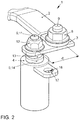
- FIG. 2 shows a perspective view of the arrangement 1, in which an insulated busbar 2 is screwed by means of a nut 8 and a threaded bolt 9 to a lever member 3.
- Die Federelement 2 ist in dem Gezzause 1 für undertake Feder 6 beprofit.
- the busbar 2 is not insulated in order to ensure transmission of electrical traction energy.
- the lever member 3 is oriented substantially perpendicular to the longitudinal extent of the busbar 2 and has at its other end a bore through which the bolt 11 of a torsion bar 5 projects and is screwed by a nut 12 rotatably.
- the mechanically effective length d of the lever element 3 overcomes an offset of the busbar 2 with respect to an axis of the torsion bar 5, which has a flange 13 below the threaded bolt 11, against which the nut 12 presses the lever element 3.
- the flange 13 rests on a flange 14 of a bushing 6, preferably made of plastic, in particular nylon, which guides the torsion bar 5 in a metallic sleeve 4.
- the bushing 6 provides a reduced frictional force between the torsion bar 5 and the sleeve 4.
- the bush 6 also serves to prevent welding at high currents between the torsion bar 5 and the sleeve 4.
- the sleeve 4 can be used as part of an electrochemical energy store be understood and provides a metallic surface for electrical connection of the cells of the electrochemical energy storage to the torsion bar 5 ready.
- the sleeve 4 has a substantially parallel, parallel or with an angle of less than 10 °, oriented to the busbar, for example.
- Laschenförmig formed structure 17 for mechanical connection in which a parallel to the longitudinal extent of the torsion bar oriented bore 18th allows a connection with the electrochemical energy storage.
- the structure 17 is arranged to stabilize the connection to the socket 6 equipped with the first end of the sleeve 4.
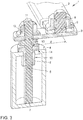
- FIG. 3 shows a sectional view of the in FIG. 2 shown arrangement 1, from which the geometry of the screw of the lever member 3 and the mounting of the torsion bar 5 within the sleeve 4 can be seen.
- a shaft 15 of the sleeve 6 has at the narrowest point between the sleeve 4 and the torsion bar 5, a taper of its outer diameter, whereby it is secured after insertion of the torsion bar 5 against displacement in the axial direction.
Landscapes
- Engineering & Computer Science (AREA)
- Chemical & Material Sciences (AREA)
- General Chemical & Material Sciences (AREA)
- Electrochemistry (AREA)
- Chemical Kinetics & Catalysis (AREA)
- Mechanical Engineering (AREA)
- Transportation (AREA)
- Life Sciences & Earth Sciences (AREA)
- Power Engineering (AREA)
- Sustainable Energy (AREA)
- Sustainable Development (AREA)
- Aviation & Aerospace Engineering (AREA)
- Combustion & Propulsion (AREA)
- Connection Of Batteries Or Terminals (AREA)
- Current-Collector Devices For Electrically Propelled Vehicles (AREA)
Claims (10)
- Arrangement pour connecter un accumulateur d'énergie (20) électrochimique à un réseau de bord d'un moyen de transport (10) pouvant être propulsé électriquement, comportant :- une barre-bus (2 ; 23, 24) destinée à conduire de l'énergie de traction électrique dans le réseau de bord,- une barre de torsion (5) et- un élément formant levier (3),la barre-bus (2 ; 23, 24), la barre de torsion (5) et l'élément formant levier (3) étant conçus électriquement conducteurs,
la barre-bus (2 ; 23, 24), la barre de torsion (5) et l'élément formant levier (3) étant reliés ensemble de manière électriquement conductrice,
une extension longitudinale de la barre-bus (2 ; 23, 24) étant orientée sensiblement perpendiculairement à une extension longitudinale de la barre de torsion (5),
et l'élément formant levier (3) possédant un décalage (d) entre l'extension longitudinale de la barre-bus (2 ; 23, 24) et l'extension longitudinale de la barre de torsion (5) . - Arrangement selon la revendication 1, comportant en outre un manchon (4) servant à guider une torsion de la barre de torsion (5).
- Arrangement selon la revendication 1 ou 2, comportant en outre une douille (6) entre le manchon (4) et la barre de torsion (5).
- Arrangement selon l'une des revendications précédentes, le manchon (4) et la barre de torsion (5) étant reliés l'un à l'autre au niveau d'une première extrémité distale (7) commune de manière électriquement conductrice et mécaniquement solidaires en rotation.
- Arrangement selon l'une des revendications précédentes, le manchon (4) possédant une structure (17) destinée à l'ancrage dans l'accumulateur d'énergie (20) électrochimique.
- Arrangement selon la revendication 5, la structure (17) possédant une languette pourvue d'un perçage (18) orienté parallèlement à l'extension longitudinale de la barre de torsion.
- Arrangement selon l'une des revendications précédentes, la barre de torsion (5) possédant au niveau d'une deuxième extrémité distale (11) un filet destiné au vissage de l'élément formant levier (3).
- Arrangement selon l'une des revendications précédentes, l'élément formant levier (3) possédant un boulon fileté (9) destiné au vissage de la barre-bus (2 ; 23, 24).
- Arrangement selon l'une des revendications précédentes, l'élément formant levier (3) étant fixé de manière rotative à la barre-bus (2 ; 23, 24).
- Moyen de transport, notamment véhicule routier pouvant être propulsé électriquement, comprenant un arrangement selon l'une des revendications précédentes.
Applications Claiming Priority (2)
| Application Number | Priority Date | Filing Date | Title |
|---|---|---|---|
| DE102015204724.5A DE102015204724A1 (de) | 2015-03-16 | 2015-03-16 | Fortbewegungsmittel und Anordnung zur Anbindung eines elektrochemischen Energiespeichers an ein Bordnetz eines elektrisch antreibbaren Fortbewegungsmittels |
| PCT/EP2015/076574 WO2016146212A1 (fr) | 2015-03-16 | 2015-11-13 | Moyen de déplacement et ensemble pour relier un accumulateur d'énergie électrochimique à un réseau de bord d'un moyen de déplacement à entraînement électrique |
Publications (2)
| Publication Number | Publication Date |
|---|---|
| EP3271955A1 EP3271955A1 (fr) | 2018-01-24 |
| EP3271955B1 true EP3271955B1 (fr) | 2019-01-09 |
Family
ID=54541084
Family Applications (1)
| Application Number | Title | Priority Date | Filing Date |
|---|---|---|---|
| EP15794194.9A Active EP3271955B1 (fr) | 2015-03-16 | 2015-11-13 | Moyen de déplacement et ensemble pour relier un accumulateur d'énergie électrochimique à un réseau de bord d'un moyen de déplacement à entraînement électrique |
Country Status (4)
| Country | Link |
|---|---|
| EP (1) | EP3271955B1 (fr) |
| CN (1) | CN107428235B (fr) |
| DE (1) | DE102015204724A1 (fr) |
| WO (1) | WO2016146212A1 (fr) |
Families Citing this family (1)
| Publication number | Priority date | Publication date | Assignee | Title |
|---|---|---|---|---|
| EP4140790B1 (fr) * | 2021-08-31 | 2024-10-09 | Volvo Truck Corporation | Support de batterie d'un véhicule |
Family Cites Families (10)
| Publication number | Priority date | Publication date | Assignee | Title |
|---|---|---|---|---|
| KR100264607B1 (ko) * | 1997-12-09 | 2000-09-01 | 정몽규 | 전기자동차용 배터리 장착구조 |
| US6161810A (en) * | 1999-02-16 | 2000-12-19 | Delphi Technologies, Inc. | Torsion rod holddown apparatus for a battery |
| DE202011000930U1 (de) * | 2011-04-19 | 2014-01-22 | Hagemann-Systems Gmbh | Batterieverbinder |
| JP2013020855A (ja) | 2011-07-12 | 2013-01-31 | Sanyo Electric Co Ltd | 電源装置及び電源装置を備える車両 |
| JP5932997B2 (ja) * | 2011-07-13 | 2016-06-08 | エルジー・ケム・リミテッド | 連結信頼性の向上した電池モジュール及びこれを備えた中大型電池パック |
| DE102012217368A1 (de) * | 2012-09-26 | 2014-03-27 | Robert Bosch Gmbh | Verbindungselement in Omega-Form zur elektrischen Verbindung von Batteriezellen eines Batteriemoduls |
| KR101428331B1 (ko) * | 2012-12-27 | 2014-08-07 | 현대자동차주식회사 | 차량용 배터리모듈의 안전장치 |
| DE102013004349A1 (de) | 2013-03-12 | 2014-09-18 | Volkswagen Aktiengesellschaft | Vorrichtung zur elektrischen Verbindung |
| CN103606637B (zh) * | 2013-11-30 | 2016-05-04 | 东莞市金源电池科技有限公司 | 一种电动车用锂电池 |
| CN103730626A (zh) * | 2014-01-24 | 2014-04-16 | 安徽江淮汽车股份有限公司 | 一种蓄电池电极连接结构及连接方法 |
-
2015
- 2015-03-16 DE DE102015204724.5A patent/DE102015204724A1/de not_active Withdrawn
- 2015-11-13 WO PCT/EP2015/076574 patent/WO2016146212A1/fr not_active Ceased
- 2015-11-13 EP EP15794194.9A patent/EP3271955B1/fr active Active
- 2015-11-13 CN CN201580077816.7A patent/CN107428235B/zh active Active
Non-Patent Citations (1)
| Title |
|---|
| None * |
Also Published As
| Publication number | Publication date |
|---|---|
| CN107428235B (zh) | 2019-09-03 |
| DE102015204724A1 (de) | 2016-09-22 |
| EP3271955A1 (fr) | 2018-01-24 |
| CN107428235A (zh) | 2017-12-01 |
| WO2016146212A1 (fr) | 2016-09-22 |
Similar Documents
| Publication | Publication Date | Title |
|---|---|---|
| EP3296143A1 (fr) | Unité de connexion pour un câble refroidi activement | |
| EP2828932A1 (fr) | Raccordement électrique anti-rotation, en particulier destiné à un élément alvéolé pouvant être chauffé électriquement | |
| EP3767752B1 (fr) | Câble électrique préassemblé, procédé de préassemblage d'un câble électrique et connecteur enfichable électrique | |
| EP3300223B1 (fr) | Dispositif de liaison amovible pour débits élevés | |
| WO2015197319A1 (fr) | Dispositif de transmission pour transmettre des signaux électriques d'au moins une cellule galvanique à au moins une unité d'évaluation électronique | |
| DE102010038407B4 (de) | Luft- oder Raumfahrzeug mit einer elektrischen Verteileranordnung | |
| DE102018203578B4 (de) | Anordnung zur elektrischen Verbindung von Polterminals sowie Zellmodul oder Batterie mit einer derartigen Verbindungsanordnung (I) | |
| EP2572396B1 (fr) | Élément de batterie lithium-ion ainsi que procédé pour établir une mise en contact électroconductrice de bornes d'éléments de batterie | |
| DE102007057501A1 (de) | Vorrichtung zur elektrischen Kontaktierung eines Steuergeräts | |
| EP3271955B1 (fr) | Moyen de déplacement et ensemble pour relier un accumulateur d'énergie électrochimique à un réseau de bord d'un moyen de déplacement à entraînement électrique | |
| DE102012202694A1 (de) | Modulare Traktionsbatterie | |
| DE102020121273A1 (de) | Elektrische Maschine mit Schutzmechanismus an einer Schweißverbindung; sowie Verfahren zur Montage der elektrischen Maschine | |
| DE102022120946A1 (de) | Vorrichtung zum elektrischen Verbinden elektrischer Komponenten, insbesondere eines elektrisch antreibbaren Fahrzeugs, mit einem kühlbaren Kontaktbereich | |
| DE102006029731B4 (de) | Batterieanschluss | |
| DE102022131094B4 (de) | Schweissverbindungsanordnung zur gekühlten stromübertragung | |
| EP2485331A2 (fr) | Borne de batterie | |
| DE102015218747A1 (de) | HV-Kabel-Anschlussanordnung | |
| EP3194238B1 (fr) | Système de jonction entre voitures pour le passage d'au moins un câble d'alimentation | |
| DE102014017869A1 (de) | Steckereinrichtung zum elektrischen Verbinden zweier Batterieeinheiten eines Kraftfahrzeugs | |
| WO2012052184A1 (fr) | Fiche d'une prise | |
| EP4239810A1 (fr) | Ensemble flottant de connecteurs enfichables et ensemble comprenant une batterie | |
| EP2524407A1 (fr) | Batterie, système de batteries et procédé de connexion d'une pluralité de batteries | |
| DE102016013799A1 (de) | Brennstoffzellenanordnung | |
| DE102019006274A1 (de) | Hochvoltbatterievorrichtung für einen Kraftwagen | |
| DE102008049377B4 (de) | Massekontaktbaugruppe zur Anordnung an einem Massebolzen |
Legal Events
| Date | Code | Title | Description |
|---|---|---|---|
| STAA | Information on the status of an ep patent application or granted ep patent |
Free format text: STATUS: THE INTERNATIONAL PUBLICATION HAS BEEN MADE |
|
| PUAI | Public reference made under article 153(3) epc to a published international application that has entered the european phase |
Free format text: ORIGINAL CODE: 0009012 |
|
| STAA | Information on the status of an ep patent application or granted ep patent |
Free format text: STATUS: REQUEST FOR EXAMINATION WAS MADE |
|
| 17P | Request for examination filed |
Effective date: 20171016 |
|
| AK | Designated contracting states |
Kind code of ref document: A1 Designated state(s): AL AT BE BG CH CY CZ DE DK EE ES FI FR GB GR HR HU IE IS IT LI LT LU LV MC MK MT NL NO PL PT RO RS SE SI SK SM TR |
|
| AX | Request for extension of the european patent |
Extension state: BA ME |
|
| DAV | Request for validation of the european patent (deleted) | ||
| DAX | Request for extension of the european patent (deleted) | ||
| GRAP | Despatch of communication of intention to grant a patent |
Free format text: ORIGINAL CODE: EPIDOSNIGR1 |
|
| STAA | Information on the status of an ep patent application or granted ep patent |
Free format text: STATUS: GRANT OF PATENT IS INTENDED |
|
| INTG | Intention to grant announced |
Effective date: 20180709 |
|
| GRAS | Grant fee paid |
Free format text: ORIGINAL CODE: EPIDOSNIGR3 |
|
| GRAA | (expected) grant |
Free format text: ORIGINAL CODE: 0009210 |
|
| STAA | Information on the status of an ep patent application or granted ep patent |
Free format text: STATUS: THE PATENT HAS BEEN GRANTED |
|
| AK | Designated contracting states |
Kind code of ref document: B1 Designated state(s): AL AT BE BG CH CY CZ DE DK EE ES FI FR GB GR HR HU IE IS IT LI LT LU LV MC MK MT NL NO PL PT RO RS SE SI SK SM TR |
|
| REG | Reference to a national code |
Ref country code: GB Ref legal event code: FG4D Free format text: NOT ENGLISH |
|
| REG | Reference to a national code |
Ref country code: CH Ref legal event code: EP Ref country code: AT Ref legal event code: REF Ref document number: 1088432 Country of ref document: AT Kind code of ref document: T Effective date: 20190115 |
|
| REG | Reference to a national code |
Ref country code: DE Ref legal event code: R096 Ref document number: 502015007648 Country of ref document: DE |
|
| REG | Reference to a national code |
Ref country code: IE Ref legal event code: FG4D Free format text: LANGUAGE OF EP DOCUMENT: GERMAN |
|
| REG | Reference to a national code |
Ref country code: NL Ref legal event code: MP Effective date: 20190109 |
|
| REG | Reference to a national code |
Ref country code: LT Ref legal event code: MG4D |
|
| PG25 | Lapsed in a contracting state [announced via postgrant information from national office to epo] |
Ref country code: NL Free format text: LAPSE BECAUSE OF FAILURE TO SUBMIT A TRANSLATION OF THE DESCRIPTION OR TO PAY THE FEE WITHIN THE PRESCRIBED TIME-LIMIT Effective date: 20190109 |
|
| PG25 | Lapsed in a contracting state [announced via postgrant information from national office to epo] |
Ref country code: PT Free format text: LAPSE BECAUSE OF FAILURE TO SUBMIT A TRANSLATION OF THE DESCRIPTION OR TO PAY THE FEE WITHIN THE PRESCRIBED TIME-LIMIT Effective date: 20190509 Ref country code: ES Free format text: LAPSE BECAUSE OF FAILURE TO SUBMIT A TRANSLATION OF THE DESCRIPTION OR TO PAY THE FEE WITHIN THE PRESCRIBED TIME-LIMIT Effective date: 20190109 Ref country code: PL Free format text: LAPSE BECAUSE OF FAILURE TO SUBMIT A TRANSLATION OF THE DESCRIPTION OR TO PAY THE FEE WITHIN THE PRESCRIBED TIME-LIMIT Effective date: 20190109 Ref country code: LT Free format text: LAPSE BECAUSE OF FAILURE TO SUBMIT A TRANSLATION OF THE DESCRIPTION OR TO PAY THE FEE WITHIN THE PRESCRIBED TIME-LIMIT Effective date: 20190109 Ref country code: SE Free format text: LAPSE BECAUSE OF FAILURE TO SUBMIT A TRANSLATION OF THE DESCRIPTION OR TO PAY THE FEE WITHIN THE PRESCRIBED TIME-LIMIT Effective date: 20190109 Ref country code: NO Free format text: LAPSE BECAUSE OF FAILURE TO SUBMIT A TRANSLATION OF THE DESCRIPTION OR TO PAY THE FEE WITHIN THE PRESCRIBED TIME-LIMIT Effective date: 20190409 Ref country code: FI Free format text: LAPSE BECAUSE OF FAILURE TO SUBMIT A TRANSLATION OF THE DESCRIPTION OR TO PAY THE FEE WITHIN THE PRESCRIBED TIME-LIMIT Effective date: 20190109 |
|
| PG25 | Lapsed in a contracting state [announced via postgrant information from national office to epo] |
Ref country code: RS Free format text: LAPSE BECAUSE OF FAILURE TO SUBMIT A TRANSLATION OF THE DESCRIPTION OR TO PAY THE FEE WITHIN THE PRESCRIBED TIME-LIMIT Effective date: 20190109 Ref country code: BG Free format text: LAPSE BECAUSE OF FAILURE TO SUBMIT A TRANSLATION OF THE DESCRIPTION OR TO PAY THE FEE WITHIN THE PRESCRIBED TIME-LIMIT Effective date: 20190409 Ref country code: GR Free format text: LAPSE BECAUSE OF FAILURE TO SUBMIT A TRANSLATION OF THE DESCRIPTION OR TO PAY THE FEE WITHIN THE PRESCRIBED TIME-LIMIT Effective date: 20190410 Ref country code: IS Free format text: LAPSE BECAUSE OF FAILURE TO SUBMIT A TRANSLATION OF THE DESCRIPTION OR TO PAY THE FEE WITHIN THE PRESCRIBED TIME-LIMIT Effective date: 20190509 Ref country code: LV Free format text: LAPSE BECAUSE OF FAILURE TO SUBMIT A TRANSLATION OF THE DESCRIPTION OR TO PAY THE FEE WITHIN THE PRESCRIBED TIME-LIMIT Effective date: 20190109 Ref country code: HR Free format text: LAPSE BECAUSE OF FAILURE TO SUBMIT A TRANSLATION OF THE DESCRIPTION OR TO PAY THE FEE WITHIN THE PRESCRIBED TIME-LIMIT Effective date: 20190109 |
|
| REG | Reference to a national code |
Ref country code: DE Ref legal event code: R097 Ref document number: 502015007648 Country of ref document: DE |
|
| PG25 | Lapsed in a contracting state [announced via postgrant information from national office to epo] |
Ref country code: IT Free format text: LAPSE BECAUSE OF FAILURE TO SUBMIT A TRANSLATION OF THE DESCRIPTION OR TO PAY THE FEE WITHIN THE PRESCRIBED TIME-LIMIT Effective date: 20190109 Ref country code: AL Free format text: LAPSE BECAUSE OF FAILURE TO SUBMIT A TRANSLATION OF THE DESCRIPTION OR TO PAY THE FEE WITHIN THE PRESCRIBED TIME-LIMIT Effective date: 20190109 Ref country code: SK Free format text: LAPSE BECAUSE OF FAILURE TO SUBMIT A TRANSLATION OF THE DESCRIPTION OR TO PAY THE FEE WITHIN THE PRESCRIBED TIME-LIMIT Effective date: 20190109 Ref country code: DK Free format text: LAPSE BECAUSE OF FAILURE TO SUBMIT A TRANSLATION OF THE DESCRIPTION OR TO PAY THE FEE WITHIN THE PRESCRIBED TIME-LIMIT Effective date: 20190109 Ref country code: CZ Free format text: LAPSE BECAUSE OF FAILURE TO SUBMIT A TRANSLATION OF THE DESCRIPTION OR TO PAY THE FEE WITHIN THE PRESCRIBED TIME-LIMIT Effective date: 20190109 Ref country code: EE Free format text: LAPSE BECAUSE OF FAILURE TO SUBMIT A TRANSLATION OF THE DESCRIPTION OR TO PAY THE FEE WITHIN THE PRESCRIBED TIME-LIMIT Effective date: 20190109 Ref country code: RO Free format text: LAPSE BECAUSE OF FAILURE TO SUBMIT A TRANSLATION OF THE DESCRIPTION OR TO PAY THE FEE WITHIN THE PRESCRIBED TIME-LIMIT Effective date: 20190109 |
|
| PLBE | No opposition filed within time limit |
Free format text: ORIGINAL CODE: 0009261 |
|
| STAA | Information on the status of an ep patent application or granted ep patent |
Free format text: STATUS: NO OPPOSITION FILED WITHIN TIME LIMIT |
|
| PG25 | Lapsed in a contracting state [announced via postgrant information from national office to epo] |
Ref country code: SM Free format text: LAPSE BECAUSE OF FAILURE TO SUBMIT A TRANSLATION OF THE DESCRIPTION OR TO PAY THE FEE WITHIN THE PRESCRIBED TIME-LIMIT Effective date: 20190109 |
|
| 26N | No opposition filed |
Effective date: 20191010 |
|
| PG25 | Lapsed in a contracting state [announced via postgrant information from national office to epo] |
Ref country code: SI Free format text: LAPSE BECAUSE OF FAILURE TO SUBMIT A TRANSLATION OF THE DESCRIPTION OR TO PAY THE FEE WITHIN THE PRESCRIBED TIME-LIMIT Effective date: 20190109 |
|
| PG25 | Lapsed in a contracting state [announced via postgrant information from national office to epo] |
Ref country code: TR Free format text: LAPSE BECAUSE OF FAILURE TO SUBMIT A TRANSLATION OF THE DESCRIPTION OR TO PAY THE FEE WITHIN THE PRESCRIBED TIME-LIMIT Effective date: 20190109 |
|
| REG | Reference to a national code |
Ref country code: CH Ref legal event code: PL |
|
| PG25 | Lapsed in a contracting state [announced via postgrant information from national office to epo] |
Ref country code: MC Free format text: LAPSE BECAUSE OF FAILURE TO SUBMIT A TRANSLATION OF THE DESCRIPTION OR TO PAY THE FEE WITHIN THE PRESCRIBED TIME-LIMIT Effective date: 20190109 Ref country code: CH Free format text: LAPSE BECAUSE OF NON-PAYMENT OF DUE FEES Effective date: 20191130 Ref country code: LU Free format text: LAPSE BECAUSE OF NON-PAYMENT OF DUE FEES Effective date: 20191113 Ref country code: LI Free format text: LAPSE BECAUSE OF NON-PAYMENT OF DUE FEES Effective date: 20191130 |
|
| REG | Reference to a national code |
Ref country code: BE Ref legal event code: MM Effective date: 20191130 |
|
| PG25 | Lapsed in a contracting state [announced via postgrant information from national office to epo] |
Ref country code: IE Free format text: LAPSE BECAUSE OF NON-PAYMENT OF DUE FEES Effective date: 20191113 |
|
| REG | Reference to a national code |
Ref country code: DE Ref legal event code: R079 Ref document number: 502015007648 Country of ref document: DE Free format text: PREVIOUS MAIN CLASS: H01M0002100000 Ipc: H01M0050200000 |
|
| PG25 | Lapsed in a contracting state [announced via postgrant information from national office to epo] |
Ref country code: BE Free format text: LAPSE BECAUSE OF NON-PAYMENT OF DUE FEES Effective date: 20191130 |
|
| PG25 | Lapsed in a contracting state [announced via postgrant information from national office to epo] |
Ref country code: CY Free format text: LAPSE BECAUSE OF FAILURE TO SUBMIT A TRANSLATION OF THE DESCRIPTION OR TO PAY THE FEE WITHIN THE PRESCRIBED TIME-LIMIT Effective date: 20190109 |
|
| PG25 | Lapsed in a contracting state [announced via postgrant information from national office to epo] |
Ref country code: HU Free format text: LAPSE BECAUSE OF FAILURE TO SUBMIT A TRANSLATION OF THE DESCRIPTION OR TO PAY THE FEE WITHIN THE PRESCRIBED TIME-LIMIT; INVALID AB INITIO Effective date: 20151113 Ref country code: MT Free format text: LAPSE BECAUSE OF FAILURE TO SUBMIT A TRANSLATION OF THE DESCRIPTION OR TO PAY THE FEE WITHIN THE PRESCRIBED TIME-LIMIT Effective date: 20190109 |
|
| REG | Reference to a national code |
Ref country code: AT Ref legal event code: MM01 Ref document number: 1088432 Country of ref document: AT Kind code of ref document: T Effective date: 20201113 |
|
| PG25 | Lapsed in a contracting state [announced via postgrant information from national office to epo] |
Ref country code: AT Free format text: LAPSE BECAUSE OF NON-PAYMENT OF DUE FEES Effective date: 20201113 |
|
| PG25 | Lapsed in a contracting state [announced via postgrant information from national office to epo] |
Ref country code: MK Free format text: LAPSE BECAUSE OF FAILURE TO SUBMIT A TRANSLATION OF THE DESCRIPTION OR TO PAY THE FEE WITHIN THE PRESCRIBED TIME-LIMIT Effective date: 20190109 |
|
| P01 | Opt-out of the competence of the unified patent court (upc) registered |
Effective date: 20230523 |
|
| PGFP | Annual fee paid to national office [announced via postgrant information from national office to epo] |
Ref country code: DE Payment date: 20241130 Year of fee payment: 10 |
|
| PGFP | Annual fee paid to national office [announced via postgrant information from national office to epo] |
Ref country code: GB Payment date: 20241126 Year of fee payment: 10 |
|
| PGFP | Annual fee paid to national office [announced via postgrant information from national office to epo] |
Ref country code: FR Payment date: 20241126 Year of fee payment: 10 |