EP3272403A2 - Verbindungselement zur verbindung zweier streckenführungselemente, streckenführungselement und streckenführungsbausatz - Google Patents
Verbindungselement zur verbindung zweier streckenführungselemente, streckenführungselement und streckenführungsbausatz Download PDFInfo
- Publication number
- EP3272403A2 EP3272403A2 EP17181423.9A EP17181423A EP3272403A2 EP 3272403 A2 EP3272403 A2 EP 3272403A2 EP 17181423 A EP17181423 A EP 17181423A EP 3272403 A2 EP3272403 A2 EP 3272403A2
- Authority
- EP
- European Patent Office
- Prior art keywords
- connecting element
- recess
- routing
- element according
- route
- Prior art date
- Legal status (The legal status is an assumption and is not a legal conclusion. Google has not performed a legal analysis and makes no representation as to the accuracy of the status listed.)
- Granted
Links
Images

Classifications
-
- A—HUMAN NECESSITIES
- A63—SPORTS; GAMES; AMUSEMENTS
- A63H—TOYS, e.g. TOPS, DOLLS, HOOPS OR BUILDING BLOCKS
- A63H18/00—Highways or trackways for toys; Propulsion by special interaction between vehicle and track
- A63H18/08—Highways or trackways for toys; Propulsion by special interaction between vehicle and track with mechanical means for guiding or steering
-
- A—HUMAN NECESSITIES
- A63—SPORTS; GAMES; AMUSEMENTS
- A63H—TOYS, e.g. TOPS, DOLLS, HOOPS OR BUILDING BLOCKS
- A63H18/00—Highways or trackways for toys; Propulsion by special interaction between vehicle and track
- A63H18/02—Construction or arrangement of the trackway
Definitions
- the invention relates to a connecting element for connecting two route guidance elements, a routing element for limiting a route for model vehicles and a route guidance kit with a connecting element according to the invention and a route guide element according to the invention.
- routing elements d. H. Set road boundaries for the formation of racetracks for remote-controlled vehicles.
- route guidance elements are commercially available, for example, which are strip-shaped and at their ends by puzzle-shaped coupling points are connected to each other.
- Two interconnected routing elements are rigidly interconnected. To form a curve, therefore, a curved routing element must be used.
- a straight track section can be formed exclusively with a straight track guide. The possibilities for producing a racetrack are therefore very limited.
- Object of the present invention is to show a way, as different routing elements can be easily connected to each other.
- a connecting element for connecting two route guide elements wherein the connecting element has a triangular basic shape with a base side and two Kathetenoxi and at least one Kathetenseite has a recess for receiving a web or projection of a route guidance element.
- two routing elements can be particularly simply be connected with each other.
- the connecting element for a connection can be made, however, be dissolved by loosening the connecting element also again.
- a race track can be built very easily and dismantled again.
- the connecting element according to the invention it is possible to connect two route guide elements substantially without play with each other.
- a web of two routing elements can come to lie in the recess, wherein the webs can abut each other.
- the connection point of two routing elements can be virtually encompassed by the connecting element.
- both catheter sides have a recess for receiving a web or projection of a route guidance element.
- a web or projection of a route guidance element Preferably, two webs or projections, each of a guide element, are received in the further recess.
- a latching element is arranged in the region of a recess.
- the connecting element can be locked with one or both route guiding elements and can thereby be arranged captive on the route guiding elements.
- no additional means are provided to secure the connection of the two route guide elements.
- the recess is formed like a groove and preferably extends over the entire length of the catheter side.
- a recess can extend over the entire length of both sides of the catheter. This results in a symmetrical configuration of the connecting element and on the other hand results in a large area connection of the two route guidance elements.
- the latching element may be formed on a groove bottom of the groove-like recess.
- a detent recess may be provided on a groove base, into which engages a detent nose of a route guidance element, preferably of two route guidance elements.
- the latching element can be arranged in the region of the base, so that the connecting element is latched against the end of insertion into a routing element.
- a web extends parallel to the groove-like recess on both sides of the recess.
- one of the webs can come to rest in a corresponding recess or groove of a route guide element to be connected.
- the width of the web can be matched to the region of the groove of the route guide element, so that a precisely fitting positive connection is formed.
- the connecting element may have an anti-twist device at its end opposite the base. Thereby, it can be prevented that the connecting member is rotated relative to a route guiding member, and the orientation of the connecting member is determined.
- the connecting element may have a slot-like recess, preferably with insertion bevels, at its end opposite the base.
- two route guiding elements can be pulled towards one another, wherein in each case one wall of the route guiding elements is introduced into the slot-like depression.
- the connecting element may taper towards its upper end.
- the webs of the connecting element to the top, d. H. away from the base, rejuvenate.
- connection element can be removed from a route guide element by a user in a particularly simple manner.
- the recessed grip can also be substantially triangular.
- the recessed grip can be spaced by gaps from the catheter sides of the connecting element.
- a route guidance element for limiting a route for model vehicles, which has at least one end of a V-shaped recess for receiving a connecting element, wherein the V-shaped recess is bounded by a web.
- the web can come to rest in the groove-like recess of the connecting element, so that thereby a positive connection can be made.
- the web may define an internal groove which serves to receive a portion of a connecting element.
- a web of the connecting element can be positively received in the groove.
- the web of the routing element may have a latching element for cooperation with a latching element of the connecting element.
- the latching element of the routing element may be formed as a latching nose, which can cooperate with a corresponding detent recess in the groove bottom of the connecting element.
- the routing element may have different shapes, so that different driving or racing tracks can be built.
- the routing element may be formed as a tee, Y-shaped or rectilinear.
- the routing element has at one end a coupling point with a first joint part, which allows a pivotable coupling with another routing element such that the set to the ground coupled route guidance elements are pivotable about a vertical pivot axis relative to each other.
- a routing element may be formed at one end to be coupled with a connecting element according to the invention with another routing element. At the opposite end, it may have a coupling point in order to produce a pivotable connection with another routing element, which is designed accordingly.
- a route guidance kit with at least one connecting element according to the invention and at least one routing element according to the invention.
- the Fig. 1 shows a front view of a connecting element 1, which has a triangular basic shape.
- the connecting element 1 has a base side 2 and two catheter sides 3, 4.
- a grip 5 is provided, which also has a substantially triangular shape.
- the recessed grip 5 is spaced by gaps 6, 7 of legs 8, 9 of the connecting element.
- the recessed grip 5 is only connected via narrow webs 10, 11, 12 with the remaining connecting element 2. By providing gaps 6, 7 material can be saved.
- the connecting element 1 has sections 13, 14 which run essentially parallel to one another.
- an anti-rotation device 15 is provided, which prevents twisting of the connecting element 1 in a routing element.
- the Fig. 2 shows a side view of the connecting element 1, in particular a view of the catheter side 3.
- the opposite side of the catheter 4 is formed analogously.
- the catheter side 3 has a particular groove-like recess 20 which is bounded on both sides by webs 21, 22.
- the recess 20 is dimensioned such that corresponding projections or webs of route guide elements to be connected find their place in the recess 20 in such a way that the route guide elements abut one another with their connecting sections.
- a slot-like recess 23 is provided in order to facilitate the insertion of the connecting element 1 or to pull two to be connected routing elements in close contact.
- a slot-like recess 23 is provided in order to facilitate the insertion of the connecting element 1 or to pull two to be connected routing elements in close contact.
- a slot-like recess 23 is provided in order to facilitate the insertion of the connecting element 1 or to pull two to be connected routing elements in close contact.
- a slot-like recess 23 is provided in order to facilitate the insertion of the connecting element 1 or to pull two to be connected routing elements in close contact.
- a slot-like recess 23 is provided in order to facilitate
- the slot-like recess 23 widens upward.
- the webs 21, 22 taper towards the upper end of the connecting element 1. This leads on the one hand to a saving of material and on the other hand to a certain flexibility of the connecting element 1 in the upper area.
- a latching element 26 is formed in the groove base of the groove-like recess 20 in the form of a latching recess. This makes it possible to lock the connecting element 1 with routing elements and thus to attach captive to the route guidance elements.
- the width of the webs 21, 22 is dimensioned so that they can be accurately inserted into corresponding grooves of route guidance elements.
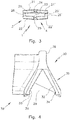
- the Fig. 3 shows a plan view of the connecting element 1.
- the features described with respect to the catheter side 3, which are also located on the catheter side 4, are identified with the same reference numeral, but with an attached apostrophe.
- Fig. 1 to 3 shows that the connecting element 1 is formed symmetrically with respect to a center plane parallel to the front and with respect to a central plane perpendicular to the front.
- the Fig. 4 shows a routing element 30 which is T-shaped.
- the routing element 30 has a V-shaped recess 29. In the area of this V-shaped recess can be in the Fig. 1 to 3 described connecting element 1 are attached.
- the v-shaped Recess 30 is limited by webs 31, 32.
- the webs 31, 32 are intended to come to rest in the groove-like recess 20 of the connecting element 1.
- locking elements 33, 34 are formed in the form of locking lugs, which cooperate with the locking elements 26, 26 'of the connecting element 1.
- the connecting element 20 has a downwardly widening first region 35, which facilitates the installation of the route guide element 30 and on the other hand ensures sufficient stability.
- the route guide element 30 is narrower and web-like in a region 36.
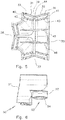
- the Fig. 5 shows a view from below of the route guide member 30.
- a total of three connection points 37, 38, 39 are provided.
- the connection point 39 is in the Fig. 4 shown in a front view.
- the webs 31, 32 each define an inner groove 40, 41.
- the inner groove 40, 41 is further limited by webs 42, 43.
- the width of the grooves 40, 41 is dimensioned so that it corresponds to the width of the webs 21, 22, 21 ', 22'.
- the webs 31, 32 come to lie in the groove-like recess 20, 20 'of the connecting element 2. They are dimensioned in their width so that they correspond to about half the width of the groove-like recess 20.
- the anti-rotation lock 15 engages in a recess 44 which is located in the section 36 of the route guide element 30.
- connection points 37, 38 are formed analogously.
- reinforcing ribs 45, 46 are provided.
- FIG. 2 shows a side view of another route guide element 50.
- the route guide element 50 is formed on one side in the same way as the connection points 37, 38, 39 of the route guide element 30.
- the side 51 of the route guide element 50 is connected to one of the connection points 37, 38, 39 of the route guide element 30 connectable by the connecting element 1.
- the route guide element 50 has a coupling point 53 with a hinge part 54, which allows a pivotable coupling with another route guide element such that the coupled to the ground coupled route guide elements are pivotable about a vertical pivot axis relative to each other.
- the routing element 50 can be used to couple different routing elements together.
- the route guide element coupled on the side 52 may have a coupling point with a hinge part at both ends.
- route guidance elements can be coupled via the coupling point 54, as described in the introduction DE 10 2011 108 719 A1 are described.
Landscapes
- Engineering & Computer Science (AREA)
- Mechanical Engineering (AREA)
- Toys (AREA)
- Electrotherapy Devices (AREA)
Abstract
Description
- Die Erfindung betrifft ein Verbindungselement zur Verbindung zweier Streckenführungselemente, ein Streckenführungselement zur Begrenzung einer Fahrstrecke für Modellfahrzeuge sowie einen Streckenführungsbausatz mit einem erfindungsgemäßen Verbindungselement und einem erfindungsgemäßen Streckenführungselement.
- Es ist bekannt, Streckenführungselemente, d. h. Fahrbahnbegrenzungen zur Ausbildung von Rennstrecken für ferngesteuerte Fahrzeuge aufzustellen. Für Modellautos im Maßstab 1:24 sind beispielsweise Streckenführungselemente im Handel erhältlich, die leistenförmig ausgebildet sind und an ihren Stirnseiten durch puzzleförmige Koppelstellen miteinander verbindbar sind. Zwei miteinander verbundene Streckenführungselemente sind dabei starr miteinander verbunden. Zur Ausbildung einer Kurve muss daher ein kurvenförmiges Streckenführungselement eingesetzt werden. Im Gegensatz dazu kann ein gerader Streckenabschnitt ausschließlich mit einem geraden Streckenführungselement ausgebildet werden. Die Möglichkeiten zur Herstellung einer Rennstrecke sind daher stark begrenzt.
- Aus der
DE 10 2011 108 719 A1 ist ein Streckenführungselement bekannt, mit dem auch Kurven besonders einfach ausgebildet werden können. Es ist jedoch nicht einfach möglich, mit einem solchen Streckenführungselement längere Geradenstrecken auszubilden oder Verzweigungen oder Kreuzungen darzustellen. - Aufgabe der vorliegenden Erfindung ist es, eine Möglichkeit aufzuzeigen, wie unterschiedliche Streckenführungselemente besonders einfach miteinander verbunden werden können.
- Gelöst wird diese Aufgabe erfindungsgemäß durch ein Verbindungselement zur Verbindung zweier Streckenführungselemente, wobei das Verbindungselement eine dreieckförmige Grundform mit einer Basisseite und zwei Kathetenseiten aufweist und zumindest eine Kathetenseite eine Ausnehmung zur Aufnahme eines Stegs oder Vorsprungs eines Streckenführungselements aufweist. Mit einem solchen Verbindungselement können zwei Streckenführungselemente besonders einfach mit einander verbunden werden. Insbesondere kann durch das Verbindungselement zum einen eine Verbindung hergestellt werden, durch Lösen des Verbindungselements jedoch auch wieder aufgelöst werden. Somit kann eine Rennstrecke besonders einfach aufgebaut und wieder abgebaut werden. Mit dem erfindungsgemäßen Verbindungselement ist es möglich, zwei Streckenführungselemente im Wesentlichen spielfrei miteinander zu verbinden. Insbesondere kann in der Ausnehmung jeweils ein Steg von zwei Streckenführungselementen zu liegen kommen, wobei die Stege aneinander anliegen können. Insbesondere kann durch das Verbindungselement die Verbindungsstelle von zwei Streckenführungselementen quasi umgriffen werden.
- Eine noch zuverlässigere Verbindung von zwei Streckenführungselementen kann dadurch realisiert werden, dass beide Kathetenseiten eine Ausnehmung zur Aufnahme eines Stegs oder Vorsprungs eines Streckenführungselements aufweisen. Vorzugsweise werden in der weiteren Ausnehmung zwei Stege oder Vorsprünge, jeweils von einem Führungselement, aufgenommen.
- Besondere Vorteile ergeben sich, wenn im Bereich einer Ausnehmung ein Rastelement angeordnet ist. Dadurch lässt sich das Verbindungselement mit einem oder beiden Streckenführungselementen verrasten und ist dadurch unverlierbar an den Streckenführungselementen anordenbar. Durch das Vorsehen einer Rastverbindung sind keine zusätzlichen Mittel vorzusehen, um die Verbindung der beiden Streckenführungselemente zu sichern.
- Weitere Vorteile ergeben sich, wenn die Ausnehmung nutartig ausgebildet ist und sich vorzugsweise über die gesamte Länge der Kathetenseite erstreckt. Insbesondere kann sich eine Ausnehmung über die gesamte Länge von beiden Kathetenseiten erstrecken. Somit ergibt sich eine symmetrische Ausgestaltung des Verbindungselements und zum anderen ergibt sich eine großflächige Verbindung der beiden Streckenführungselemente.
- Dabei kann das Rastelement an einem Nutgrund der nutartigen Ausnehmung ausgebildet sein. Insbesondere kann an einem Nutgrund eine Rastmulde vorgesehen sein, in die eine Rastnase eines Streckenführungselements, vorzugsweise von zwei Streckenführungselementen, eingreift. Das Rastelement kann dabei im Bereich der Basis angeordnet sein, sodass das Verbindungselement erst gegen Ende des Einsteckens in ein Streckenführungselement verrastet.
- Besonders vorteilhaft ist es, wenn sich beidseits der Ausnehmung jeweils ein Steg parallel zur nutartigen Ausnehmung erstreckt. Jeweils einer der Stege kann dabei in einer entsprechenden Ausnehmung oder Nut eines zu verbindenden Streckenführungselements zu liegen kommen. Die Breite des Stegs kann dabei auf den Bereich der Nut des Streckenführungselements abgestimmt sein, sodass eine passgenaue formschlüssige Verbindung entsteht.
- Das Verbindungselement kann an seinem der Basis gegenüberliegenden Ende eine Verdrehsicherung aufweisen. Dadurch kann verhindert werden, dass sich das Verbindungselement relativ zu einem Streckenführungselement verdreht, und wird die Orientierung des Verbindungselements festgelegt.
- Das Verbindungselement kann an seinem der Basis gegenüberliegenden Ende eine schlitzartige Ausnehmung, vorzugsweise mit Einführschrägen, aufweisen. Durch diese Ausgestaltung des oberen Endes des Verbindungselements können zwei Streckenführungselemente aufeinander zu gezogen werden, wobei jeweils eine Wandung der Streckenführungselemente in die schlitzartige Vertiefung eingeführt wird. Das Verbindungselement kann sich zu seinem oberen Ende hin verjüngen. Insbesondere können sich die Stege des Verbindungselements nach oben hin, d. h. von der Basisseite weg, verjüngen.
- Die Handhabbarkeit des Verbindungselements wird erleichtert, wenn eine Griffmulde vorgesehen ist. Dadurch lässt sich das Verbindungselement durch einen Benutzer besonders einfach wieder von einem Streckenführungselement entfernen. Dabei kann die Griffmulde im Wesentlichen ebenfalls dreieckförmig gestaltet sein. Die Griffmulde kann durch Zwischenräume von den Kathetenseiten des Verbindungselements beabstandet sein.
- In den Rahmen der Erfindung fällt außerdem ein Streckenführungselement zur Begrenzung einer Fahrstrecke für Modellfahrzeuge, welches an zumindest einem Ende eine v-förmige Ausnehmung zur Aufnahme eines Verbindungselements aufweist, wobei die v-förmige Ausnehmung durch einen Steg begrenzt wird. Der Steg kann dabei in der nutartigen Ausnehmung des Verbindungselements zum Liegen kommen, sodass dadurch eine formschlüssige Verbindung hergestellt werden kann.
- Der Steg kann eine innenliegende Nut, die der Aufnahme eines Abschnitts eines Verbindungselements dient, begrenzen. Insbesondere kann ein Steg des Verbindungselements formschlüssig in der Nut aufgenommen werden.
- Der Steg des Streckenführungselements kann ein Rastelement zur Zusammenwirkung mit einem Rastelement des Verbindungselements aufweisen. Insbesondere kann das Rastelement des Streckenführungselements als Rastnase ausgebildet sein, die mit einer entsprechenden Rastmulde im Nutgrund des Verbindungselements zusammenwirken kann.
- Das Streckenführungselement kann unterschiedliche Formen aufweisen, sodass unterschiedliche Fahr- oder Rennstrecken aufgebaut werden können. Insbesondere kann das Streckenführungselement als T-Stück, Y-förmig oder geradlinig ausgebildet sein.
- Weitere Vorteile ergeben sich, wenn das Streckenführungselement an einem Ende eine Koppelstelle mit einem ersten Gelenkteil aufweist, das eine schwenkbare Kopplung mit einem weiteren Streckenführungselement derart erlaubt, dass die auf den Untergrund gestellten gekoppelten Streckenführungselemente relativ zueinander um eine vertikale Schwenkachse schwenkbar sind. Somit kann ein Streckenführungselement an einem Ende ausgebildet sein, um mit einem erfindungsgemäßen Verbindungselement mit einem weiteren Streckenführungselement gekoppelt zu werden. Am gegenüberliegenden Ende kann es eine Koppelstelle aufweisen, um eine schwenkbar Verbindung mit einem anderen Streckenführungselement, das entsprechend ausgebildet ist, herstellen zu können.
- Es sind jedoch auch Streckenführungselemente denkbar, die an zwei oder mehr Enden für die Verbindung mit einem erfindungsgemäßen Verbindungselement ausgebildet sind.
- Weiterhin fällt in den Rahmen der Erfindung ein Streckenführungsbausatz mit zumindest einem erfindungsgemäßen Verbindungselement und zumindest einem erfindungsgemäßen Streckenführungselement.
- Weitere Merkmale und Vorteile der Erfindung ergeben sich aus der nachfolgenden detaillierten Beschreibung von Ausführungsbeispielen der Erfindung, anhand der Figuren der Zeichnung, die erfindungswesentliche Einzelheiten zeigt, sowie aus den Ansprüchen. Die dort gezeigten Merkmale sind nicht notwendig maßstäblich zu verstehen und derart dargestellt, dass die erfindungsgemäßen Besonderheiten deutlich sichtbar gemacht werden können. Die verschiedenen Merkmale können je einzeln für sich oder zu mehreren in beliebigen Kombinationen bei Varianten der Erfindung verwirklicht sein.
- In der schematischen Zeichnung sind Ausführungsbeispiele der Erfindung dargestellt und in der nachfolgenden Beschreibung näher erläutert.
- Es zeigen:
- Fig. 1
- eine Ansicht von vorn auf ein Verbindungselement;
- Fig. 2
- eine Seitenansicht des Verbindungselements;
- Fig. 3
- eine Draufsicht auf das Verbindungselement;
- Fig. 4
- eine Draufsicht auf einen ersten Verbindungsbereich eines Streckenführungselements;
- Fig. 5
- eine Draufsicht von unten auf ein Streckenführungselement;
- Fig. 6
- eine Seitenansicht eines Streckenführungselements.
- Die
Fig. 1 zeigt eine Ansicht von vorn eines Verbindungselements 1, welches eine dreieckförmige Grundform aufweist. Das Verbindungselement 1 weist eine Basisseite 2 und zwei Kathetenseiten 3, 4 auf. In einem zentralen Bereich ist eine Griffmulde 5 vorgesehen, die ebenfalls eine im Wesentlichen dreieckförmige Gestalt aufweist. Die Griffmulde 5 ist durch Zwischenräume 6, 7 von Schenkeln 8, 9 des Verbindungselements beabstandet. Insbesondere ist die Griffmulde 5 lediglich über schmale Stege 10, 11, 12 mit dem übrigen Verbindungselement 2 verbunden. Durch das Vorsehen von Zwischenräumen 6, 7 kann Material eingespart werden. In einem unteren Bereich weist das Verbindungselement 1 im Wesentlichen parallel zueinander verlaufende Abschnitte 13, 14 auf. Im oberen Bereich ist eine Verdrehsicherung 15 vorgesehen, die ein Verdrehen des Verbindungselements 1 in einem Streckenführungselement verhindert. - Die
Fig. 2 zeigt eine Seitenansicht des Verbindungselements 1, insbesondere eine Ansicht auf die Kathetenseite 3. Die gegenüberliegende Kathetenseite 4 ist analog ausgebildet. - Der
Fig. 2 kann man entnehmen, dass die Kathetenseite 3 eine insbesondere nutartig ausgebildete Ausnehmung 20 aufweist, die beidseits von Stegen 21, 22 begrenzt wird. Die Ausnehmung 20 ist so bemessen, dass entsprechende Vorsprünge oder Stege von zu verbindenden Streckenführungselementen so in der Ausnehmung 20 Platz finden, dass die Streckenführungselemente mit ihren Verbindungsabschnitten aneinander anliegen. Um das Einführen des Verbindungselements 1 zu erleichtern bzw. um zwei zu verbindende Streckenführungselemente in enge Anlage zu ziehen, ist eine schlitzartige Ausnehmung 23 vorgesehen. Sie erstreckt sich in Verlängerung der nutartigen Ausnehmung 20. Insbesondere wird die schlitzartige Ausnehmung 23 durch die Verdrehsicherung 15 begrenzt. Am oberen Ende der schlitzartigen Ausnehmung 23 sind Einführschrägen 24, 25 vorgesehen. Somit erweitert sich die schlitzartige Ausnehmung 23 nach oben hin. Gleichzeitig ist zu erkennen, dass sich die Stege 21, 22 zum oberen Ende des Verbindungselements 1 hin verjüngen. Dies führt zum einen zu einer Materialersparnis und zum anderen zu einer gewissen Flexibilität des Verbindungselements 1 im oberen Bereich. - Im Bereich der Basisseite 2 ist im Nutgrund der nutartigen Ausnehmung 20 ein Rastelement 26 in Form einer Rastmulde ausgebildet. Dies ermöglicht es, das Verbindungselement 1 mit Streckenführungselementen zu verrasten und damit unverlierbar an den Streckenführungselementen anzubringen.
- Die Breite der Stege 21, 22 ist so bemessen, dass sie passgenau in entsprechende Nuten von Streckenführungselementen eingebracht werden können.
- Die
Fig. 3 zeigt eine Draufsicht auf das Verbindungselement 1. Die bezüglich der Kathetenseite 3 beschriebenen Merkmale, die sich auch auf der Kathetenseite 4 befinden, werden mit der gleichen Bezugsziffer, jedoch mit einem angefügten Apostroph gekennzeichnet. - Aus den
Fig. 1 bis 3 ergibt sich, dass das Verbindungselement 1 bezüglich einer Mittenebene parallel zur Vorderseite und bezüglich einer Mittenebene senkrecht zur Vorderseite symmetrisch ausgebildet ist. - Die
Fig. 4 zeigt ein Streckenführungselement 30, welches T-förmig ausgebildet ist. An einer Verbindungsstelle 39 weist das Streckenführungselement 30 eine v-förmige Ausnehmung 29 auf. Im Bereich dieser v-förmigen Ausnehmung kann ein in denFig. 1 bis 3 beschriebenes Verbindungselement 1 angebracht werden. Die v-förmige Ausnehmung 30 ist durch Stege 31, 32 begrenzt. Die Stege 31, 32 sind dafür vorgesehen, in der nutartigen Ausnehmung 20 des Verbindungselements 1 zu liegen zu kommen. An den Stegen 31, 32 sind Rastelemente 33, 34 in Form von Rastnasen ausgebildet, die mit den Rastelementen 26, 26' des Verbindungselements 1 zusammenwirken. - Das Verbindungselement 20 weist einen sich nach unten verbreiternden ersten Bereich 35 auf, der das Aufstellen des Streckenführungselements 30 erleichtert und zum anderen für eine hinreichende Stabilität sorgt. Im oberen Bereich ist das Streckenführungselement 30 in einen Bereich 36 schmaler und stegartig ausgebildet.
- Die
Fig. 5 zeigt eine Ansicht von unten des Streckenführungselements 30. Hier ist zu erkennen, dass insgesamt drei Verbindungsstellen 37, 38, 39 vorgesehen sind. Die Verbindungsstelle 39 ist in derFig. 4 in einer Vorderansicht gezeigt. In derFig. 5 ist erkennbar, dass die Stege 31, 32 jeweils eine innen liegende Nut 40, 41 begrenzen. Die innen liegende Nut 40, 41 wird weiterhin durch Stege 42, 43 begrenzt. Die Breite der Nuten 40, 41 ist so bemessen, dass sie der Breite der Stege 21, 22, 21', 22' entspricht. Die Stege 31, 32 kommen in der nutartigen Ausnehmung 20, 20' der Verbindungselements 2 zu liegen. Sie sind in ihrer Breite so bemessen, dass sie etwa der Hälfte der Breite der nutartigen Ausnehmung 20 entsprechen. - Die Verdrehsicherung 15 greift in eine Ausnehmung 44 ein, die sich im Abschnitt 36 des Streckenführungselements 30 befindet.
- Die anderen Verbindungsstellen 37, 38 sind analog ausgebildet. Zur Verstärkung des Streckenführungselements 30 sind Verstärkungsrippen 45, 46 vorgesehen.
- Die
Fig. 6 zeigt eine Seitenansicht eines weiteren Streckenführungselements 50. Das Streckenführungselement 50 ist auf der einen Seite so ausgebildet wie die Verbindungsstellen 37, 38, 39 des Streckenführungselements 30. Somit ist die Seite 51 des Streckenführungselements 50 mit einer der Verbindungsstellen 37, 38, 39 des Streckenführungselements 30 durch das Verbindungselement 1 verbindbar. - Auf der gegenüberliegenden Seite 52 weist das Streckenführungselement 50 eine Koppelstelle 53 auf mit einem Gelenkteil 54, das eine schwenkbare Kopplung mit einem weiteren Streckenführungselement derart erlaubt, dass die auf den Untergrund gestellten gekoppelten Streckenführungselemente relativ zueinander um eine vertikale Schwenkachse schwenkbar sind.
- Das Streckenführungselement 50 kann dabei verwendet werden, um unterschiedliche Streckenführungselemente miteinander zu koppeln. Das auf der Seite 52 gekoppelte Streckenführungselement kann an beiden Enden eine Koppelstelle mit einem Gelenkteil aufweisen. Es ist jedoch auch denkbar, ein Streckenführungselement ähnlich dem Streckenführungselement 50 zu koppeln, wobei dieses eine komplementäre Koppelstelle benötigt, um mit der Koppelstelle 53 gekoppelt werden zu können. Insbesondere können über die Koppelstelle 54 Streckenführungselemente gekoppelt werden, wie sie in der eingangs genannten
DE 10 2011 108 719 A1 beschrieben sind.
Claims (15)
- Verbindungselement (1) zur Verbindung zweier Streckenführungselemente (30), wobei das Verbindungselement (1) eine dreieckförmige Grundform mit einer Basisseite (2) und zwei Kathetenseiten (3, 4) aufweist und zumindest eine Kathetenseite (3, 4) eine Ausnehmung (20, 20') zur Aufnahme eines Stegs (31, 32) oder Vorsprungs eines Streckenführungselements (30) aufweist.
- Verbindungselement nach Anspruch 1, dadurch gekennzeichnet, dass beide Kathetenseiten (3, 4) eine Ausnehmung (20, 20') zur Aufnahme eines Stegs (31, 32) oder Vorsprungs eines Streckenführungselements (30) aufweisen.
- Verbindungselement nach einem der vorhergehenden Ansprüche, dadurch gekennzeichnet, dass im Bereich einer Ausnehmung (20, 20') ein Rastelement (26, 26') angeordnet ist.
- Verbindungselement nach einem der vorhergehenden Ansprüche, dadurch gekennzeichnet, dass die Ausnehmung (20, 20') nutartig ausgebildet ist und sich vorzugsweise über die gesamte Länge der Kathetenseite (3, 4) erstreckt.
- Verbindungselement nach einem der vorhergehenden Ansprüche, dadurch gekennzeichnet, dass das Rastelement (26, 26') an einem Nutgrund der nutartigen Ausnehmung ausgebildet ist.
- Verbindungselement nach einem der vorhergehenden Ansprüche, dadurch gekennzeichnet, dass sich beidseits der Ausnehmung (20, 20') jeweils ein Steg (21, 22, 21', 22') parallel zur nutartigen Ausnehmung (20, 20') erstreckt.
- Verbindungselement nach einem der vorhergehenden Ansprüche, dadurch gekennzeichnet, dass das Verbindungselement (1) an seinem der Basis (2) gegenüberliegenden Ende eine Verdrehsicherung (15) aufweist.
- Verbindungselement nach einem der vorhergehenden Ansprüche, dadurch gekennzeichnet, dass das Verbindungselement (1) an seinem der Basis (2) gegenüberliegenden Ende eine schlitzartige Ausnehmung (23), vorzugsweise mit Einführschrägen (24, 25), aufweist.
- Verbindungselement nach einem der vorhergehenden Ansprüche, dadurch gekennzeichnet, dass eine Griffmulde (5) vorgesehen ist.
- Streckenführungselement (30, 50) zur Begrenzung einer Fahrstrecke für Modellfahrzeuge, welches an zumindest einem Ende eine v-förmige Ausnehmung (29) zur Aufnahme eines Verbindungselements (1) aufweist, wobei die v-förmige Ausnehmung (29) durch einen Steg (31, 32) begrenzt wird.
- Streckenführungselement nach Anspruch 10, dadurch gekennzeichnet, dass der Steg (31, 32) eine innen liegende Nut (40, 41), die der Aufnahme eines Abschnitts eines Verbindungselements (1) dient, begrenzt.
- Streckenführungselement nach einem der vorhergehenden Ansprüche 10 oder 11, dadurch gekennzeichnet, dass der Steg (31, 32) ein Rastelement (33, 34) zur Zusammenwirkung mit einem Rastelement (26, 26') des Verbindungselements (1) aufweist.
- Streckenführungselement nach einem der vorhergehenden Ansprüche, dadurch gekennzeichnet, dass es als T-Stück, Y-förmig oder geradlinig ausgebildet ist.
- Streckenführungselement nach einem der vorhergehenden Ansprüche, dadurch gekennzeichnet, dass es an einem Ende eine Koppelstelle (53) mit einem ersten Gelenkteil (54) aufweist, das eine schwenkbare Kopplung mit dem weiteren Streckenführungselement derart erlaubt, dass die auf den Untergrund gestellten gekoppelten Streckenführungselemente relativ zueinander um eine vertikale Schwenkachse schwenkbar sind.
- Streckenführungsbausatz mit zumindest einem Verbindungselement (1) nach einem der Ansprüche 1 - 9 und zumindest einem Streckenführungselement (30, 50) nach einem der Ansprüche 10 - 14.
Priority Applications (1)
| Application Number | Priority Date | Filing Date | Title |
|---|---|---|---|
| PL17181423T PL3272403T3 (pl) | 2016-07-21 | 2017-07-14 | Element łączący do połączenia dwóch elementów bariery toru, element bariery toru i zestaw konstrukcyjny bariery toru |
Applications Claiming Priority (1)
| Application Number | Priority Date | Filing Date | Title |
|---|---|---|---|
| DE202016103970.3U DE202016103970U1 (de) | 2016-07-21 | 2016-07-21 | Verbindungselement zur Verbindung zweier Streckenführungselemente, Streckenführungselement und Streckenführungsbausatz |
Publications (3)
| Publication Number | Publication Date |
|---|---|
| EP3272403A2 true EP3272403A2 (de) | 2018-01-24 |
| EP3272403A3 EP3272403A3 (de) | 2018-04-04 |
| EP3272403B1 EP3272403B1 (de) | 2019-07-03 |
Family
ID=56738409
Family Applications (1)
| Application Number | Title | Priority Date | Filing Date |
|---|---|---|---|
| EP17181423.9A Active EP3272403B1 (de) | 2016-07-21 | 2017-07-14 | Verbindungselement zur verbindung zweier streckenführungselemente, streckenführungselement und streckenführungsbausatz |
Country Status (4)
| Country | Link |
|---|---|
| EP (1) | EP3272403B1 (de) |
| DE (1) | DE202016103970U1 (de) |
| ES (1) | ES2748563T3 (de) |
| PL (1) | PL3272403T3 (de) |
Citations (1)
| Publication number | Priority date | Publication date | Assignee | Title |
|---|---|---|---|---|
| DE102011108719A1 (de) | 2011-07-28 | 2013-01-31 | Rainer Andreas Czak | Streckenführungselement |
Family Cites Families (5)
| Publication number | Priority date | Publication date | Assignee | Title |
|---|---|---|---|---|
| CH443095A (de) * | 1965-11-08 | 1967-08-31 | Burgstaller Rolf | Bausatz für Spielzeug-Hochbahn |
| US3958361A (en) * | 1971-03-22 | 1976-05-25 | Ideal Toy Corporation | Track segment with braking elements which retain vehicle vertically during braking |
| DE3103505A1 (de) * | 1981-02-03 | 1982-08-12 | Gebr. Fleischmann, 8500 Nürnberg | Schienenverbindung fuer elektrische spiel- und modellbahnen |
| US5421762A (en) * | 1991-09-13 | 1995-06-06 | Connector Set Limited Partnership | Vehicle track for construction toy system |
| US5203733A (en) * | 1991-11-13 | 1993-04-20 | Patch Bryce L | Toy car racetrack assembled from multiple paperboard blanks |
-
2016
- 2016-07-21 DE DE202016103970.3U patent/DE202016103970U1/de active Active
-
2017
- 2017-07-14 EP EP17181423.9A patent/EP3272403B1/de active Active
- 2017-07-14 ES ES17181423T patent/ES2748563T3/es active Active
- 2017-07-14 PL PL17181423T patent/PL3272403T3/pl unknown
Patent Citations (1)
| Publication number | Priority date | Publication date | Assignee | Title |
|---|---|---|---|---|
| DE102011108719A1 (de) | 2011-07-28 | 2013-01-31 | Rainer Andreas Czak | Streckenführungselement |
Also Published As
| Publication number | Publication date |
|---|---|
| DE202016103970U1 (de) | 2016-08-03 |
| PL3272403T3 (pl) | 2019-12-31 |
| EP3272403A3 (de) | 2018-04-04 |
| ES2748563T3 (es) | 2020-03-17 |
| EP3272403B1 (de) | 2019-07-03 |
Similar Documents
| Publication | Publication Date | Title |
|---|---|---|
| DE10348852A1 (de) | Schalungssystem | |
| EP2550855A1 (de) | Begrenzungsmauer mit Versteifungsvorrichtung | |
| DE8118239U1 (de) | Laufplanke fuer ein geruest | |
| DE202006003836U1 (de) | Deckenschalungssystem | |
| DE102008045518B4 (de) | Betonschutzwand | |
| DE102014106068B4 (de) | Vorrichtung zur Verbindung zweier einander gegenüberliegender plattenförmiger Schalungselemente | |
| EP3272403B1 (de) | Verbindungselement zur verbindung zweier streckenführungselemente, streckenführungselement und streckenführungsbausatz | |
| DE10348264B3 (de) | Feststeller für eingenutete Rückwände an Kastenmöbeln | |
| DE102016113478A1 (de) | Verbindungselement zur Verbindung zweier Streckenführungselemente, Streckenführungselement und Streckenführungsbausatz | |
| EP1717456B1 (de) | Steckverbindung mit Stabilisator | |
| EP2447434A1 (de) | Metallische Deckenunterkonstruktion | |
| EP1702120A1 (de) | Schalungssystem | |
| DE102011108719B4 (de) | Streckenführungselement | |
| DE19707689C1 (de) | Kabelbrücke | |
| AT13915U1 (de) | Gitterträger | |
| EP3427572A1 (de) | Einfassung zum aufnehmen von erd- und/oder kompostmaterial | |
| DE4441769C2 (de) | Steckverbinder für Sprossenprofile | |
| DE202014003122U1 (de) | Technischer Spielzeugbaukasten Holz - Kunststoff | |
| DE729692C (de) | Zweiteiliger Metallduebel zur Verbindung von hoelzernen Baugliedern | |
| DE602006000265T2 (de) | Halter | |
| DE8218690U1 (de) | Haltevorrichtung | |
| AT411771B (de) | Randstein | |
| DE19549550C2 (de) | Transportsystem für Betonteile | |
| DE202015007893U1 (de) | Stecker-Kupplungs-Vorrichtung zur Montage an einem Bauelement einer Spielzeugbahn, Steckervorrichtung und Kupplungsvorrichtung | |
| DE1793266U (de) | Modell-konstruktionsteil. |
Legal Events
| Date | Code | Title | Description |
|---|---|---|---|
| PUAI | Public reference made under article 153(3) epc to a published international application that has entered the european phase |
Free format text: ORIGINAL CODE: 0009012 |
|
| STAA | Information on the status of an ep patent application or granted ep patent |
Free format text: STATUS: THE APPLICATION HAS BEEN PUBLISHED |
|
| AK | Designated contracting states |
Kind code of ref document: A2 Designated state(s): AL AT BE BG CH CY CZ DE DK EE ES FI FR GB GR HR HU IE IS IT LI LT LU LV MC MK MT NL NO PL PT RO RS SE SI SK SM TR |
|
| AX | Request for extension of the european patent |
Extension state: BA ME |
|
| PUAL | Search report despatched |
Free format text: ORIGINAL CODE: 0009013 |
|
| AK | Designated contracting states |
Kind code of ref document: A3 Designated state(s): AL AT BE BG CH CY CZ DE DK EE ES FI FR GB GR HR HU IE IS IT LI LT LU LV MC MK MT NL NO PL PT RO RS SE SI SK SM TR |
|
| AX | Request for extension of the european patent |
Extension state: BA ME |
|
| RIC1 | Information provided on ipc code assigned before grant |
Ipc: A63H 18/02 20060101AFI20180223BHEP |
|
| STAA | Information on the status of an ep patent application or granted ep patent |
Free format text: STATUS: REQUEST FOR EXAMINATION WAS MADE |
|
| 17P | Request for examination filed |
Effective date: 20181004 |
|
| RBV | Designated contracting states (corrected) |
Designated state(s): AL AT BE BG CH CY CZ DE DK EE ES FI FR GB GR HR HU IE IS IT LI LT LU LV MC MK MT NL NO PL PT RO RS SE SI SK SM TR |
|
| RIC1 | Information provided on ipc code assigned before grant |
Ipc: A63H 18/02 20060101AFI20181219BHEP |
|
| GRAP | Despatch of communication of intention to grant a patent |
Free format text: ORIGINAL CODE: EPIDOSNIGR1 |
|
| STAA | Information on the status of an ep patent application or granted ep patent |
Free format text: STATUS: GRANT OF PATENT IS INTENDED |
|
| INTG | Intention to grant announced |
Effective date: 20190301 |
|
| GRAS | Grant fee paid |
Free format text: ORIGINAL CODE: EPIDOSNIGR3 |
|
| GRAA | (expected) grant |
Free format text: ORIGINAL CODE: 0009210 |
|
| STAA | Information on the status of an ep patent application or granted ep patent |
Free format text: STATUS: THE PATENT HAS BEEN GRANTED |
|
| AK | Designated contracting states |
Kind code of ref document: B1 Designated state(s): AL AT BE BG CH CY CZ DE DK EE ES FI FR GB GR HR HU IE IS IT LI LT LU LV MC MK MT NL NO PL PT RO RS SE SI SK SM TR |
|
| REG | Reference to a national code |
Ref country code: GB Ref legal event code: FG4D Free format text: NOT ENGLISH |
|
| REG | Reference to a national code |
Ref country code: AT Ref legal event code: REF Ref document number: 1150283 Country of ref document: AT Kind code of ref document: T Effective date: 20190715 Ref country code: CH Ref legal event code: NV Representative=s name: ROTTMANN, ZIMMERMANN + PARTNER AG, CH Ref country code: CH Ref legal event code: EP |
|
| REG | Reference to a national code |
Ref country code: IE Ref legal event code: FG4D Free format text: LANGUAGE OF EP DOCUMENT: GERMAN |
|
| REG | Reference to a national code |
Ref country code: DE Ref legal event code: R096 Ref document number: 502017001675 Country of ref document: DE |
|
| REG | Reference to a national code |
Ref country code: NL Ref legal event code: FP |
|
| REG | Reference to a national code |
Ref country code: NO Ref legal event code: T2 Effective date: 20190703 |
|
| REG | Reference to a national code |
Ref country code: LT Ref legal event code: MG4D |
|
| PG25 | Lapsed in a contracting state [announced via postgrant information from national office to epo] |
Ref country code: PT Free format text: LAPSE BECAUSE OF FAILURE TO SUBMIT A TRANSLATION OF THE DESCRIPTION OR TO PAY THE FEE WITHIN THE PRESCRIBED TIME-LIMIT Effective date: 20191104 Ref country code: FI Free format text: LAPSE BECAUSE OF FAILURE TO SUBMIT A TRANSLATION OF THE DESCRIPTION OR TO PAY THE FEE WITHIN THE PRESCRIBED TIME-LIMIT Effective date: 20190703 Ref country code: LT Free format text: LAPSE BECAUSE OF FAILURE TO SUBMIT A TRANSLATION OF THE DESCRIPTION OR TO PAY THE FEE WITHIN THE PRESCRIBED TIME-LIMIT Effective date: 20190703 Ref country code: HR Free format text: LAPSE BECAUSE OF FAILURE TO SUBMIT A TRANSLATION OF THE DESCRIPTION OR TO PAY THE FEE WITHIN THE PRESCRIBED TIME-LIMIT Effective date: 20190703 Ref country code: SE Free format text: LAPSE BECAUSE OF FAILURE TO SUBMIT A TRANSLATION OF THE DESCRIPTION OR TO PAY THE FEE WITHIN THE PRESCRIBED TIME-LIMIT Effective date: 20190703 Ref country code: BG Free format text: LAPSE BECAUSE OF FAILURE TO SUBMIT A TRANSLATION OF THE DESCRIPTION OR TO PAY THE FEE WITHIN THE PRESCRIBED TIME-LIMIT Effective date: 20191003 |
|
| PG25 | Lapsed in a contracting state [announced via postgrant information from national office to epo] |
Ref country code: RS Free format text: LAPSE BECAUSE OF FAILURE TO SUBMIT A TRANSLATION OF THE DESCRIPTION OR TO PAY THE FEE WITHIN THE PRESCRIBED TIME-LIMIT Effective date: 20190703 Ref country code: GR Free format text: LAPSE BECAUSE OF FAILURE TO SUBMIT A TRANSLATION OF THE DESCRIPTION OR TO PAY THE FEE WITHIN THE PRESCRIBED TIME-LIMIT Effective date: 20191004 Ref country code: IS Free format text: LAPSE BECAUSE OF FAILURE TO SUBMIT A TRANSLATION OF THE DESCRIPTION OR TO PAY THE FEE WITHIN THE PRESCRIBED TIME-LIMIT Effective date: 20191103 Ref country code: LV Free format text: LAPSE BECAUSE OF FAILURE TO SUBMIT A TRANSLATION OF THE DESCRIPTION OR TO PAY THE FEE WITHIN THE PRESCRIBED TIME-LIMIT Effective date: 20190703 Ref country code: AL Free format text: LAPSE BECAUSE OF FAILURE TO SUBMIT A TRANSLATION OF THE DESCRIPTION OR TO PAY THE FEE WITHIN THE PRESCRIBED TIME-LIMIT Effective date: 20190703 |
|
| REG | Reference to a national code |
Ref country code: ES Ref legal event code: FG2A Ref document number: 2748563 Country of ref document: ES Kind code of ref document: T3 Effective date: 20200317 |
|
| REG | Reference to a national code |
Ref country code: BE Ref legal event code: MM Effective date: 20190731 |
|
| PG25 | Lapsed in a contracting state [announced via postgrant information from national office to epo] |
Ref country code: DK Free format text: LAPSE BECAUSE OF FAILURE TO SUBMIT A TRANSLATION OF THE DESCRIPTION OR TO PAY THE FEE WITHIN THE PRESCRIBED TIME-LIMIT Effective date: 20190703 Ref country code: EE Free format text: LAPSE BECAUSE OF FAILURE TO SUBMIT A TRANSLATION OF THE DESCRIPTION OR TO PAY THE FEE WITHIN THE PRESCRIBED TIME-LIMIT Effective date: 20190703 Ref country code: RO Free format text: LAPSE BECAUSE OF FAILURE TO SUBMIT A TRANSLATION OF THE DESCRIPTION OR TO PAY THE FEE WITHIN THE PRESCRIBED TIME-LIMIT Effective date: 20190703 |
|
| PG25 | Lapsed in a contracting state [announced via postgrant information from national office to epo] |
Ref country code: SK Free format text: LAPSE BECAUSE OF FAILURE TO SUBMIT A TRANSLATION OF THE DESCRIPTION OR TO PAY THE FEE WITHIN THE PRESCRIBED TIME-LIMIT Effective date: 20190703 Ref country code: BE Free format text: LAPSE BECAUSE OF NON-PAYMENT OF DUE FEES Effective date: 20190731 Ref country code: SM Free format text: LAPSE BECAUSE OF FAILURE TO SUBMIT A TRANSLATION OF THE DESCRIPTION OR TO PAY THE FEE WITHIN THE PRESCRIBED TIME-LIMIT Effective date: 20190703 Ref country code: IS Free format text: LAPSE BECAUSE OF FAILURE TO SUBMIT A TRANSLATION OF THE DESCRIPTION OR TO PAY THE FEE WITHIN THE PRESCRIBED TIME-LIMIT Effective date: 20200224 Ref country code: LU Free format text: LAPSE BECAUSE OF NON-PAYMENT OF DUE FEES Effective date: 20190714 Ref country code: MC Free format text: LAPSE BECAUSE OF FAILURE TO SUBMIT A TRANSLATION OF THE DESCRIPTION OR TO PAY THE FEE WITHIN THE PRESCRIBED TIME-LIMIT Effective date: 20190703 |
|
| REG | Reference to a national code |
Ref country code: DE Ref legal event code: R097 Ref document number: 502017001675 Country of ref document: DE |
|
| PLBE | No opposition filed within time limit |
Free format text: ORIGINAL CODE: 0009261 |
|
| STAA | Information on the status of an ep patent application or granted ep patent |
Free format text: STATUS: NO OPPOSITION FILED WITHIN TIME LIMIT |
|
| PG2D | Information on lapse in contracting state deleted |
Ref country code: IS |
|
| PG25 | Lapsed in a contracting state [announced via postgrant information from national office to epo] |
Ref country code: IE Free format text: LAPSE BECAUSE OF NON-PAYMENT OF DUE FEES Effective date: 20190714 |
|
| 26N | No opposition filed |
Effective date: 20200603 |
|
| PG25 | Lapsed in a contracting state [announced via postgrant information from national office to epo] |
Ref country code: SI Free format text: LAPSE BECAUSE OF FAILURE TO SUBMIT A TRANSLATION OF THE DESCRIPTION OR TO PAY THE FEE WITHIN THE PRESCRIBED TIME-LIMIT Effective date: 20190703 |
|
| PG25 | Lapsed in a contracting state [announced via postgrant information from national office to epo] |
Ref country code: CY Free format text: LAPSE BECAUSE OF FAILURE TO SUBMIT A TRANSLATION OF THE DESCRIPTION OR TO PAY THE FEE WITHIN THE PRESCRIBED TIME-LIMIT Effective date: 20190703 |
|
| PG25 | Lapsed in a contracting state [announced via postgrant information from national office to epo] |
Ref country code: HU Free format text: LAPSE BECAUSE OF FAILURE TO SUBMIT A TRANSLATION OF THE DESCRIPTION OR TO PAY THE FEE WITHIN THE PRESCRIBED TIME-LIMIT; INVALID AB INITIO Effective date: 20170714 Ref country code: MT Free format text: LAPSE BECAUSE OF FAILURE TO SUBMIT A TRANSLATION OF THE DESCRIPTION OR TO PAY THE FEE WITHIN THE PRESCRIBED TIME-LIMIT Effective date: 20190703 |
|
| PG25 | Lapsed in a contracting state [announced via postgrant information from national office to epo] |
Ref country code: MK Free format text: LAPSE BECAUSE OF FAILURE TO SUBMIT A TRANSLATION OF THE DESCRIPTION OR TO PAY THE FEE WITHIN THE PRESCRIBED TIME-LIMIT Effective date: 20190703 |
|
| PGFP | Annual fee paid to national office [announced via postgrant information from national office to epo] |
Ref country code: PL Payment date: 20250415 Year of fee payment: 9 |
|
| PGFP | Annual fee paid to national office [announced via postgrant information from national office to epo] |
Ref country code: NL Payment date: 20250723 Year of fee payment: 9 |
|
| PGFP | Annual fee paid to national office [announced via postgrant information from national office to epo] |
Ref country code: ES Payment date: 20250819 Year of fee payment: 9 |
|
| PGFP | Annual fee paid to national office [announced via postgrant information from national office to epo] |
Ref country code: DE Payment date: 20250728 Year of fee payment: 9 |
|
| PGFP | Annual fee paid to national office [announced via postgrant information from national office to epo] |
Ref country code: NO Payment date: 20250722 Year of fee payment: 9 |
|
| PGFP | Annual fee paid to national office [announced via postgrant information from national office to epo] |
Ref country code: IT Payment date: 20250731 Year of fee payment: 9 Ref country code: TR Payment date: 20250708 Year of fee payment: 9 |
|
| PGFP | Annual fee paid to national office [announced via postgrant information from national office to epo] |
Ref country code: GB Payment date: 20250724 Year of fee payment: 9 |
|
| PGFP | Annual fee paid to national office [announced via postgrant information from national office to epo] |
Ref country code: AT Payment date: 20250721 Year of fee payment: 9 Ref country code: FR Payment date: 20250723 Year of fee payment: 9 |
|
| PGFP | Annual fee paid to national office [announced via postgrant information from national office to epo] |
Ref country code: CH Payment date: 20250801 Year of fee payment: 9 |
|
| PGFP | Annual fee paid to national office [announced via postgrant information from national office to epo] |
Ref country code: CZ Payment date: 20250701 Year of fee payment: 9 |
|
| REG | Reference to a national code |
Ref country code: CH Ref legal event code: R17 Free format text: ST27 STATUS EVENT CODE: U-0-0-R10-R17 (AS PROVIDED BY THE NATIONAL OFFICE) Effective date: 20260410 |