EP3272437B1 - Procédé de formage à la presse et outil de formage à la presse - Google Patents
Procédé de formage à la presse et outil de formage à la presse Download PDFInfo
- Publication number
- EP3272437B1 EP3272437B1 EP16764534.0A EP16764534A EP3272437B1 EP 3272437 B1 EP3272437 B1 EP 3272437B1 EP 16764534 A EP16764534 A EP 16764534A EP 3272437 B1 EP3272437 B1 EP 3272437B1
- Authority
- EP
- European Patent Office
- Prior art keywords
- forming
- blank
- side wall
- press
- punch
- Prior art date
- Legal status (The legal status is an assumption and is not a legal conclusion. Google has not performed a legal analysis and makes no representation as to the accuracy of the status listed.)
- Active
Links
Images




Classifications
-
- B—PERFORMING OPERATIONS; TRANSPORTING
- B21—MECHANICAL METAL-WORKING WITHOUT ESSENTIALLY REMOVING MATERIAL; PUNCHING METAL
- B21D—WORKING OR PROCESSING OF SHEET METAL OR METAL TUBES, RODS OR PROFILES WITHOUT ESSENTIALLY REMOVING MATERIAL; PUNCHING METAL
- B21D19/00—Flanging or other edge treatment, e.g. of tubes
- B21D19/08—Flanging or other edge treatment, e.g. of tubes by single or successive action of pressing tools, e.g. vice jaws
-
- B—PERFORMING OPERATIONS; TRANSPORTING
- B21—MECHANICAL METAL-WORKING WITHOUT ESSENTIALLY REMOVING MATERIAL; PUNCHING METAL
- B21D—WORKING OR PROCESSING OF SHEET METAL OR METAL TUBES, RODS OR PROFILES WITHOUT ESSENTIALLY REMOVING MATERIAL; PUNCHING METAL
- B21D22/00—Shaping without cutting, by stamping, spinning, or deep-drawing
- B21D22/02—Stamping using rigid devices or tools
-
- B—PERFORMING OPERATIONS; TRANSPORTING
- B21—MECHANICAL METAL-WORKING WITHOUT ESSENTIALLY REMOVING MATERIAL; PUNCHING METAL
- B21D—WORKING OR PROCESSING OF SHEET METAL OR METAL TUBES, RODS OR PROFILES WITHOUT ESSENTIALLY REMOVING MATERIAL; PUNCHING METAL
- B21D22/00—Shaping without cutting, by stamping, spinning, or deep-drawing
- B21D22/20—Deep-drawing
-
- B—PERFORMING OPERATIONS; TRANSPORTING
- B21—MECHANICAL METAL-WORKING WITHOUT ESSENTIALLY REMOVING MATERIAL; PUNCHING METAL
- B21D—WORKING OR PROCESSING OF SHEET METAL OR METAL TUBES, RODS OR PROFILES WITHOUT ESSENTIALLY REMOVING MATERIAL; PUNCHING METAL
- B21D37/00—Tools as parts of machines covered by this subclass
- B21D37/10—Die sets; Pillar guides
-
- B—PERFORMING OPERATIONS; TRANSPORTING
- B21—MECHANICAL METAL-WORKING WITHOUT ESSENTIALLY REMOVING MATERIAL; PUNCHING METAL
- B21D—WORKING OR PROCESSING OF SHEET METAL OR METAL TUBES, RODS OR PROFILES WITHOUT ESSENTIALLY REMOVING MATERIAL; PUNCHING METAL
- B21D22/00—Shaping without cutting, by stamping, spinning, or deep-drawing
- B21D22/20—Deep-drawing
- B21D22/21—Deep-drawing without fixing the border of the blank
-
- B—PERFORMING OPERATIONS; TRANSPORTING
- B21—MECHANICAL METAL-WORKING WITHOUT ESSENTIALLY REMOVING MATERIAL; PUNCHING METAL
- B21D—WORKING OR PROCESSING OF SHEET METAL OR METAL TUBES, RODS OR PROFILES WITHOUT ESSENTIALLY REMOVING MATERIAL; PUNCHING METAL
- B21D22/00—Shaping without cutting, by stamping, spinning, or deep-drawing
- B21D22/20—Deep-drawing
- B21D22/30—Deep-drawing to finish articles formed by deep-drawing
Definitions
- the present invention relates to a press forming method and a tool of press forming used for a metal sheet, and particularly relates to a press forming method and a tool of press forming that are capable of preventing an occurrence of wrinkles during a crash forming process.
- high-strength steel sheets have been widely used in many automotive parts to realize weight reduction of automotive bodies to respond to environmental issues.
- press forming processes are often used because press forming processes are excellent in view of manufacturing costs.
- high-strength steel sheets have a lower level of ductility than low-strength steel sheets, during a deep drawing process in which a blank holder force is applied while a tip end portion of a blank is gripped by a blank holder, a large strain tends to occur in the vicinity of the tip end portion of the blank, which may easily lead to a fracture of the sheet.
- a crash forming process is preferably used in many occasions, which is a kind of press forming process that primarily uses a bending deformation process without using the blank holder.
- a crash forming process because the tension applied to a blank is small, excess metal caused by a shape of the manufactured component part may easily become a direct cause of wrinkles. It is therefore difficult to manufacture a press-formed product having a desired shape.
- Patent Literature 1 describes a method for manufacturing an L-shaped product by performing a pressing process. According to this method, it is indicated that, by performing the pressing process while using a pad for preventing wrinkles, it is possible to avoid the occurrence of wrinkles in the top portion of the L-shape product and to avoid the occurrence of a fracture during a stretch flange forming process.
- Patent Literature 2 discloses a method for manufacturing a component part that has an arc-shaped portion in a corner portion thereof, without generating wrinkles in a side wall portion thereof. This method includes: a step of manufacturing an intermediate formed product having no arc-shaped portion formed therein; and a step of completing the corner portion by performing a drawing process to form the arc-shaped portion in the intermediate formed product manufactured at the preceding step. It is indicated that it is possible to avoid the occurrence of wrinkles by making one or more incisions in such a section that does not reach the arc-shaped portion, the incisions each starting from the edge side of a flange portion.
- Patent Literature 3 discloses a tool of press forming which applies a bending deformation process to make a hat-shaped cross section from a steel blank sheet and immediately after the bending deformation process is completed, to apply a compressive stress to a side wall portion of the steel blank sheet.
- Examples of methods for preventing the occurrence of wrinkles during a press forming process include a method in which buckling of a blank caused by excess metal is prevented by applying a padding force in advance to a section where wrinkles may occur, by using a pad mechanism for preventing wrinkles that is powered separately from the pressing machine.
- this method is applicable to a top portion of a part that can be held between a punch and a pad in an initial stage of the press forming process, this method is not applicable to a side wall portion of a part that has a large inclination angle with respect to the drive direction of the pressing machine.
- Patent Literature 2 has a disadvantage in terms of productivity because the manufacturing process of the component part requires at least two steps. In addition, because it is necessary to make the incisions in the blank, a problem arises where there is a possibility that the component part may have a shape different from an originally-intended shape.
- the side wall portion is compressed by moving an upper bending blade of a die sideways with the use of a suspended slider that is slidably attached to an upper section of the tool, so as to pinch and hold the upper half of the side wall portion, while pressing the lower half thereof.
- a press forming process of a component part having a side wall portion that curves outward in terms of the longitudinal direction which is to be dealt with in the present application, it would be necessary to vary the shape of the upper bending blade of the tool of press forming in accordance with the curvature of the curving during the bending deformation process, because the curvature of the curving of the side wall portion changes during the bending deformation process.
- a press forming method for forming a press-formed product having no flange portion from a blank by performing a crash forming process while using a die and a punch, the press-formed product including at least a top portion and a side wall portion continued from the top portion via a connecting portion and being structured so that either all or a part of the side wall portion curves toward an outside of the press-formed product to form a convex shape in a planar view, the press forming method including forming the side wall portion while keeping a tip end portion of the blank in continuous contact with a side wall forming portion of the die and causing the die to impose no restrain on any part other than the tip end portion of the blank.
- the tip end portion of the blank of the above invention corresponds to an extent from a tip end of the blank defined by a distance up to four times longer than a thickness of the blank.
- a tool of press forming according to the present invention is used by the press forming method according to any of the above inventions and includes the punch and the die.
- a tool of press forming for forming a press-formed product having no flange portion by performing a crash forming process and including at least a top portion and a side wall portion continued from the top portion via a connecting portion and being structured so that either all or a part of the side wall portion curves toward an outside of the press-formed product to form a convex shape in a planar view.
- the tool of press forming includes a punch that has a forming top portion on which a blank is placed, a punch shoulder portion that is continued from the forming top portion and extends along the curving of the press-formed product, and a forming wall portion continued from the punch shoulder portion; and a die that has a side wall forming portion that forms the side wall portion of the press-formed product by moving relative to the punch.
- an X-Y coordinate system in which an origin is a point serving as a center of a radius curvature of the curving on the forming top portion, while an X-axis corresponds to a horizontal direction, whereas a Y-axis corresponds to a vertical direction
- a curve drawn by a formula presented below is referred to as an optimal curve
- an inclination angle of a tangential line of the optimal curve at an arbitrary X-coordinate position is referred to as an optimal inclination angle
- the side wall forming portion of the die has a cross-sectional shape expressed with a curve where an inclination angle of a tangential line at the arbitrary X-coordinate position with respect to the horizontal direction is equal to or greater than the optimal inclination angle.
- the press forming method and the tool of press forming according to the present invention achieves an advantageous effect where it is possible to easily form the side wall portion curving toward the outside of the press-formed product to have a convex shape in a planar view, in the single step without the need to make incisions in the blank, while preventing the occurrence of wrinkles.
- a press-formed product 11 having no flange portion is formed by performing a crash forming process while using a tool of press forming 1 illustrated in FIG. 1 .
- the press-formed product 11 includes, at least, a top portion 13 and a side wall portion 15 that is continued from the top portion 13 via a connecting portion 14. Either all or a part of the side wall portion 15 curves toward the outside to have a convex shape in a planar view.
- the side wall portion 15 of the press-formed product 11 is formed by constantly keeping a tip end portion of a blank 3 in contact with the die 9 in such a manner that, in a side wall forming portion 9a, the die 9 imposes no restraint other than keeping the tip end portion in contact therewith.
- the press-formed product 11 having the side wall portion 15 that curves toward the outside to have a convex shape in a planar view as illustrated in FIG. 2 is manufactured by performing a conventional crash forming process
- the height of the side wall portion 15 of the press-formed product 11 is equal to or greater than a certain level
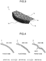
- wrinkles 19 occur (see FIG. 3 ), because a shrink deformation is concentrated at a lower end of the side wall portion 15. It is considered that the wrinkles occur due to a mechanism which is explained below.
- the deformation at the tip end portion requires shrink deformation energy in an in-plane direction as well as deformation energy to increase the thickness.
- the press-formed product 11 is formed so as to have a desired shape of the present invention, it is possible to prevent wrinkles from occurring on the outside, by arranging the die 9 to press the tip end portion of the blank 3 so as not to spread outwardly, as illustrated in FIG. 1 .
- FIG. 4 illustrates a horizontal cross-section (a cross-section of the blank 3 sectioned in a direction parallel to the plane of the top portion 13 illustrated in FIG. 3 ) of the blank 3 used in the tip end portion of the side wall portion 15 of the press-formed product 11.
- the tip end portion of the blank 3 by arranging the die 9 to press down the tip end portion of the blank 3 from the outside thereof and to keep the tip end portion in contact therewith, while the die 9 imposes no restraint other than keeping the tip end portion in contact therewith, it is possible to prevent the tip end portion from being deformed outwardly and to prevent the occurrence of wrinkles in the tip end portion. Further, the state where the wrinkles can easily occur toward the outside remains from a certain point in time during the forming process, up to the end of the forming process. It is therefore necessary to constantly keep the tip end portion of the blank 3 in contact with the die 9, so as to press down the tip end portion from the outside thereof.
- the first embodiment presents the press forming method in which the crash forming process is performed while the top face of the blank 3 is being pressed by the pad 7 as illustrated in FIG. 1 . It should be noted that, however, even when a forming process is performed without arranging the pad 7 to press the blank 3, it is possible to form the side wall portion 15 in such a manner that the side wall portion 15 of the press-formed product 11 has no wrinkles, as long as the tip end portion of the blank 3 is constantly kept in contact with the side wall forming portion 9a of the die 9 during the forming process in such a manner that no restraint is imposed on the tip end portion of the blank 3 other than keeping the tip end portion in contact.
- the tip end portion of the blank 3 kept in contact with the side wall forming portion 9a of the die 9 during the forming process corresponds to an extent from the tip end of the blank 3 defined by a distance up to four times longer than the thickness of the blank 3, as described in the first example below.
- this condition it is possible to form the side wall portion 15 in such a manner that the side wall portion 15 has no wrinkles.
- a tool of press forming 1 according to the second embodiment will be explained, with reference to FIG. 1 illustrating a state during the forming process.
- the tool of press forming 1 according to the second embodiment of the present invention includes, at least, the top portion 13 and the side wall portion 15 that is continued from the top portion 13 via the connecting portion 14, as illustrated in FIG. 2 similar to the first embodiment explained above, so as to form the press-formed product 11 in which either all or a part of the side wall portion 15 curves toward the outside to have a convex shape in a planar view. As illustrated in FIG.
- the tool of press forming 1 includes: the punch 5 that supports the lower face of the blank 3 that is tabular-shaped; the pad 7 that presses the top face of the blank 3 supported by a forming top portion 5a of the punch 5; and the die 9 that performs a bending process while the side wall forming portion 9a thereof abuts against the blank 3 held between the punch 5 and the pad 7.
- the punch 5 includes: the forming top portion 5a; a punch shoulder portion 5b that is a shoulder portion of the punch which continues downward at an angle from an end of the forming top portion 5a; and a forming wall portion 5c that continues downward from a lower end side of the punch shoulder portion 5b.
- the forming top portion 5a supports the lower face of the blank 3, which is a flat face.
- the cross-sectional shape of the punch shoulder portion 5b is an arc having a radius curvature R.
- the pad 7 is arranged so as to oppose the forming top portion 5a of the punch 5 and is configured so as to be raised and lowered.
- the die 9 performs the bending deformation process on the blank 3 while abutting against the blank 3 and includes the side wall forming portion 9a that forms the side wall portion 15 of the press-formed product 11.
- the cross-sectional shape of the side wall forming portion 9a is curved as illustrated in FIG. 1 . Because the cross-sectional shape of the side wall forming portion 9a is arranged to be curved, it is possible to constantly keep the tip end portion of the blank 3 in contact with the side wall forming portion 9a during the forming process. Alternatively, as explained later, by using a die 39 that has a side wall forming portion 39a of which the cross-sectional shape is a straight line as illustrated in FIG. 5 , it is also possible to constantly keep the tip end portion of the blank 3 in contact with the side wall forming portion 39a during the forming process.
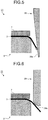
- FIGS. 6 to 9 a requirement for the cross-sectional shape of the side wall forming portion 9a of the die 9 to constantly keep the tip end portion of the blank 3 in contact with the die 9 will be explained with reference to FIGS. 6 to 9 .
- FIGS. 6 to 9 some of the sections that are the same as, or that correspond to, those in FIG. 1 will be referred to by using the same reference signs.
- the cross-sectional shape of a die shoulder portion 29b is determined by the cross-sectional shape of a connecting portion connecting together the side wall portion and the flange portion of the press-formed product.
- the press-formed product 11 having no flange portion as targeted by the present invention is formed by performing a press forming process while using the conventional tool of press forming 21, it is possible for the die shoulder portion 29b to have any cross-sectional shape regardless of the shape of the product resulting from the forming process of the press-formed product 11, except that the press-formed product 11 may have a forming defect such as a crack or wrinkles after the press forming process.
- the inclination angle, with respect to the horizontal direction, of the tip end of the blank 3 corresponding to the side wall portion 15 of the press-formed product 11 varies during the forming process.
- the inventors of the present application have discovered that it is possible to constantly keep the tip end of the blank 3 in contact with the side wall forming portion 9a without the need to determine the forming stroke to be long, by arranging the cross-sectional shape of the side wall forming portion 9a to be a cross-sectional shape expressed by a curve where the inclination angle of the side wall forming portion 9a with respect to the horizontal direction changes in accordance with the position in which the tip end of the blank 3 is in contact with the die 9 during the forming process.
- the specific cross-sectional shape in which the inclination angle of the side wall forming portion 9a with respect to the horizontal direction changes was determined in the following manner.
- the radius of the punch (hereinafter referred to as "punch radius”) on a plane parallel to the horizontal direction of the forming top portion 5a of the punch 5 is expressed as “pr” [mm]
- the radius curvature of the punch shoulder portion 5b is expressed as "R” [mm]
- the radius of the blank 3 (hereinafter referred to as "blank radius”) on a plane parallel to the horizontal direction of the forming top portion 5a is expressed as "br" [mm]
- the thickness of the blank 3 is expressed as "t” [mm].
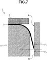
- a distance L from the point (the point A in FIG. 8 ) where the blank 3 becomes apart from the punch shoulder portion 5b as a result of the bending deformation process performed thereon while the blank 3 abutting against the punch shoulder portion 5b, to the tip end of the blank 3 can be expressed by using the formula presented below, where the contact angle " ⁇ " [rad] of the blank 3 with respect to the punch shoulder portion 5b is used as a parameter.
- L br ⁇ pr ⁇ R ⁇ R + t 2 ⁇
- a locus of the tip end position of the blank 3 during the forming process as a point (x, y) expressed by the following formula in an x-y coordinate system in which the origin O is the point serving as the center of the radius curvature of the curve in the horizontal direction on the forming top portion 5a, while the x-axis corresponds to the horizontal direction of the forming top portion 5a, whereas the y-axis corresponds to the vertical direction of the forming top portion 5a.
- the angle ⁇ B formed by the horizontal direction and the direction parallel to the section of the blank 3 at the tip end of the blank 3 kept in contact with the side wall forming portion 9a is equal to the contact angle ⁇ of the blank 3 with respect to the punch shoulder portion 5b. Accordingly, in order for the side wall forming portion 9a of the die 9 to have a cross-sectional shape so as to be constantly kept in contact with the tip end of the blank 3, it is necessary that the inclination angle ⁇ indicating the angle of the side wall forming portion 9a with respect to the horizontal direction at the point (the point B in FIG. 9 ) where the tip end of the blank 3 is kept in contact be equal to or greater than the angle ⁇ B at all times. It is therefore necessary that the contact angle ⁇ of the blank 3 with respect to the punch shoulder portion 5b and the inclination angle ⁇ satisfy the relationship expressed in Expression (1) presented below: ⁇ ⁇ ⁇
- FIG. 11 illustrates an example of the side wall forming portion 9a having the optimal cross-sectional shape determined by using the method described above.
- the condition defined in Expression (1) is satisfied at all times during the forming process, as long as the cross-sectional shape of the side wall forming portion 9a is such a cross-sectional shape (hereinafter referred to as a "tolerable cross-sectional shape") that is expressed with a curve where the inclination angle of the tangential line at the arbitrary X-coordinate position with respect to the horizontal line is equal to or greater than the optimal inclination angle.
- FIGS. 12-A to 12-C are drawings that illustrate examples of tolerable cross-sectional shapes of the side wall forming portion 9a that satisfy Expression (1). It is assumed that the tip end of the blank 3 is, without fail, in contact with the side wall forming portion 9a at the start of the press forming process.
- FIG. 12A illustrates Example 1 of the tolerable cross-sectional shape of the side wall forming portion 9a.
- the tolerable cross-sectional shape in Example 1 is a tolerable cross-sectional shape expressed with an inclined surface of which the inclination angle ⁇ 2 is constant. In Example 1, as illustrated in FIG. 12A , the inclination angle ⁇ 2 is greater than the optimal inclination angle ⁇ 1 .
- FIG. 12B illustrates Example 2 of the tolerable cross-sectional shape of the side wall forming portion 9a.
- the tolerable cross-sectional shape in Example 2 is a tolerable cross-sectional shape obtained by applying analogous enlargement to the optimal cross-sectional shape. As illustrated in FIG.
- FIG. 12C illustrates Example 3 of the tolerable cross-sectional shape of the side wall forming portion 9a.
- the tolerable cross-sectional shape in Example 3 is a tolerable cross-sectional shape expressed with an arc having a large radius curvature.
- the inclination angle ⁇ 2 of the tangential line of the arc at an arbitrary X-coordinate position is greater than the optimal inclination angle ⁇ 1 .
- the cross-sectional shape of the side wall forming portion 9a satisfies the condition defined in Expression (1) in any of the examples illustrated in FIGS. 12A to 12C . It is therefore possible to perform the bending deformation process while constantly keeping the tip end of the blank 3 in contact with the side wall forming portion 9a.
- the cross-sectional shape of the side wall forming portion 9a may be a tolerable cross-sectional shape that is expressed, as illustrated in FIG. 13A , with a curve where the inclination angle ⁇ 2 (not illustrated in FIG. 13A ) of the tangential line at the arbitrary X-coordinate position with respect to the horizontal direction decreases in an intermediate section.
- the cross-sectional shape of the side wall forming portion 9a is a cross-sectional shape that is expressed, as illustrated in FIG. 13B for example, with a curve where the inclination angle ⁇ 2 of the tangential line at a certain X-coordinate position X A is less than the optimal inclination angle ⁇ 1 .
- Such cross-sectional shapes that do not satisfy the condition defined in Expression (1) are intolerable cross-sectional shapes that are not tolerable for the side wall forming portion 9a.
- the cross-sectional shape of the side wall forming portion 9a is an intolerable cross-sectional shape, a section other than the tip end of the blank 3 comes into contact with the side wall forming portion 9a.
- the side wall forming portion 9a has a cross-sectional shape such as that illustrated in FIG. 13B . It should be noted that, however, when the cross-sectional shape of the side wall forming portion 9a is such a shape that the extent from the tip end of the blank 3 defined by a distance up to four times longer than the thickness of the blank 3 is constantly kept in contact with the side wall forming portion 9a during the side wall forming process, it is possible to prevent the occurrence of wrinkles.
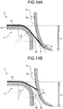
- the contact angle of the basic blank 41 with respect to the punch shoulder portion 5b is expressed as " ⁇ ", when the moving distance of the die 9 is expressed as "Ls", while using the height of the forming top portion 5a of the punch 5 as a reference.
- the inclination angle of the tangential line of the die 9 with respect to the horizontal direction at the point (the point A in FIG. 14A ) where the tip end of the basic blank 41 is in contact with the side wall forming portion 9a is expressed as " ⁇ 1 ".
- the contact angle of the smaller blank 43 with respect to the punch shoulder portion 5b is expressed as " ⁇ '", when the moving distance of the die 9 toward the punch 5 side is expressed as "Ls".
- the inclination angle of the tangential line of the die 9 with respect to the horizontal direction at the point (the point B in FIG. 14B ) where the tip end of the smaller blank 43 is in contact with the side wall forming portion 9a is expressed as " ⁇ 2 ".
- the contact angle ⁇ ' of the smaller blank 43 is less than the contact angle ⁇ of the basic blank 41 at all times, regardless of the value of the moving distance Ls of the die 9. Further, the inclination angle ⁇ 2 of the tangential line of the die 9 at the point where the tip end of the smaller blank 43 is in contact with the side wall forming portion 9a is greater than the contact angle ⁇ '. Accordingly, when a forming process is performed on the smaller blank 43 by using the die 9 having the side wall forming portion 9a of which the cross-sectional shape is determined on the basis of the basic blank 41, the relationship defined in Expression (1) is always satisfied.
- the section in which the cross-sectional shape of the side wall forming portion 9a of the die 9 is determined in the manner described above may be applied to only a target section for which the occurrence of wrinkles is to be prevented in the side wall portion 15 of the press-formed product 11.
- the cross-section determination process may be whole of the side wall portion 15.
- the radius curvature of the side wall portion 15 curving toward the outside to have a convex shape in a planar view is not constant throughout the whole of the side wall portion 15, it may be a good idea to design the die 9, by dividing the side wall portion 15 into sections in each of which the radius curvature of the curve is the same, determining a cross-sectional shape of the side wall forming portion 9a of the die 9 for each of the divided sections by using the method described above, and joining together the cross-sectional shapes determined for the divided sections to form the side wall forming portion 9a.
- a first example corresponds to a situation where a crash forming process is performed to form a press-formed product 51 that has a side wall portion 55 continued from a disc-shaped top portion 53 via a connecting portion 54 illustrated in FIG. 15 .
- the radius r of the top portion 53 was 90 [mm]
- the radius curvature of the connecting portion 54 was 8 [mm].
- two types of blanks 3 were used for forming the press-formed product 51, namely, a steel sheet A that had a thickness t of 1.2 [mm] and had a tensile strength of 590 [MPa] grade; and a steel sheet B that had a thickness t of 1.6 [mm] and had a tensile strength of 590 [MPa] grade.
- the blank 3 had a disc shape of which the radius (the blank radius) was 105 [mm] for the steel sheet A and was 107 [mm] for the steel sheet B.
- the punch radius of the punch 5 was 90 [mm]
- the radius curvature of the punch shoulder portion 5b was 8 [mm].
- the forming process is performed while only the tip end of the blank 3 is in contact with the side wall forming portion 9a.
- the side wall forming portion 9a has a cross-sectional shape determined by using another value br less than the blank radius of the blank 3
- the forming process is performed while a tip end portion including a section positioned on the inside of the tip end of the blank 3 is in contact with the side wall forming portion 9a.
- the greater the difference is between the blank radius of the blank 3 and the value of br in Expression (2), the greater the extent of the tip end portion that is in contact with the side wall forming portion 9a becomes.
- Table 1 illustrates results regarding whether wrinkles occurred or not in the side wall portions 55 of the press-formed products 51 and the extent (the distance) "a" of the tip end portion of the blank 3 that was in contact with the side wall forming portion 9a, when the crash forming process was performed on the steel sheet A and the steel sheet B under the abovementioned conditions.
- the radius curvature of the cross-sectional plane of the connecting portion 14 connecting together the top portion 13 and the side wall portion 15 was 5 [mm]
- the radius curvature of the curve on a plane parallel to the horizontal direction of the top portion 13 was 80 [mm].
- the blank 3 was a steel sheet that had a thickness of 1.2 [mm] and a tensile strength of 980 [MPa] grade.
- the blank radius of the blank 3 denotes, as illustrated in FIG. 16 , the radius curvature of the curve at the tip end portion of the blank 3.
- Example 2 In the second example, it was checked to see whether wrinkles occurred or not by varying the press-formed-product height h of the press-formed product 11 in each of these situations.
- Example 1 of the present invention and Example 2 of the present invention As indicated in Table 2, in Example 1 of the present invention and Example 2 of the present invention, no wrinkles occurred in the side wall portion 15 of the press-formed product 11, regardless of the values of the blank radius. In particular, even when the blank radius was 100 [mm], it was possible to form the side wall portion 15 without any wrinkles. As understood from Table 2, the results from Example 1 of the present invention and Example 2 of the present invention were better than those from Comparative Example 1 formed by using the conventional tool of press forming 21.
- Example 1 of the present invention was 80 [mm]
- the forming stroke in Example 2 of the present invention was 470 [mm]. It was therefore possible to prevent the forming stroke from increasing, by arranging the side wall forming portion 9a of the die 9 to have the optimal cross-sectional shape A.
- the press-formed product 51 has the top portion 53 and the side wall portion 55.
- the top portion 53 and the side wall portion 55 are connected together in continuity by the connecting portion 54 represented by an arc-shaped curved plane having a constant curvature.
- the height of the side wall portion 55 corresponds to the height of the press-formed product 51 (i.e., the press-formed-product height h).
- the press-formed product 51 was formed by using a steel sheet serving as the blank 3 that had a thickness of 1.2 mm and a tensile strength of 590 [MPa] grade, while using the tool of press forming 1 of which the cross-section is illustrated in FIG. 1 .
- the radius r of the top portion 53 was 90 [mm]
- the radius curvature of the connecting portion 54 connecting together the top portion 53 and the side wall portion 55 was 8 [mm].
- an analysis was performed on these two types of side wall forming portions 9a.
- the third example corresponds to situations where advantageous effects of the present invention were verified by making comparisons with crash forming processes performed by using the conventional tool of press forming 21 as illustrated in FIG. 6 .
- Two types of the conventional tool of press forming 21 were used, namely, one in which the die shoulder portion 29b had a radius curvature of 8 [mm] (Comparative Example 2) and the other in which the die shoulder portion 29b had a radius curvature of 2 [mm]
- the third example corresponds to situations where a crash forming process was performed on each of the blanks 3 having mutually-different radius values, while using either the tool of press forming 1 (either Example 3 or Example 4 of the present invention) of which the side wall forming portion 9a had the optimal cross-sectional shape or the conventional tool of press forming 21 (either Comparative Example 2 or Comparative Example 3).
- the third example it was checked to see whether wrinkles occurred or not in the side wall portion 55 of each of the obtained press-formed products 51. Results from the third example are presented in Table 3.
- Comparative Example 2 As indicated in Table 3, compared to Comparative Example 3 in which the radius curvature of the die shoulder portion 29b was 2 [mm], Comparative Example 2 having a greater radius curvature exhibited a slightly better wrinkle prevention effect. However, by using the tool of press forming 1 including the side wall forming portion 9a that had either the optimal cross-sectional shape B or the optimal cross-sectional shape C presented as Examples 3 and 4 of the present invention, it was possible to press-form the side wall portion 55 of the press-formed product 51 without any wrinkles, with even greater blank radius values.
- the press forming method and the tool of press forming according to the present invention are useful in the crash forming processes of the press-formed products.
- the press forming method and the tool of press forming are suitable as a press forming method and a tool of press forming used for easily forming, in a single step, the side wall portion curving toward the outside of the press-formed product to have a convex shape in a planar view, while preventing the occurrence of wrinkles.
Landscapes
- Engineering & Computer Science (AREA)
- Mechanical Engineering (AREA)
- Shaping Metal By Deep-Drawing, Or The Like (AREA)
- Bending Of Plates, Rods, And Pipes (AREA)
Claims (2)
- Procédé de formage à la presse pour former un produit formé à la presse (11) n'ayant pas de partie bridée à partir d'une ébauche en réalisant un procédé de formage d'urgence tout en utilisant une matrice (9) et un poinçon (5),
dans lequel le poinçon a une partie supérieure de formage (5a) sur laquelle une ébauche (3) est placée, une partie d'épaulement de poinçon (5b) qui prolonge la partie supérieure de formage et s'étend le long de la courbe du produit formé à la presse, et une partie de paroi de formage (5c) prolongeant la partie d'épaulement de poinçon ; et
la matrice a une partie de formage de paroi latérale (9a) qui forme la partie de paroi latérale (15) du produit formé à la presse (11) en se déplaçant par rapport au poinçon, dans lequel, dans un système de coordonnées X-Y, dans lequel une origine (O) est un point servant de centre de rayon de courbure de la courbe sur la partie supérieure de formage, tandis qu'un axe X correspond à une direction horizontale et qu'un axe Y correspond à une direction verticale, une courbe tracée par une formule présentée ci-dessous est considérée comme une courbe optimale, tandis qu'un angle d'inclinaison d'une ligne tangentielle de la courbe optimale dans une position arbitraire des coordonnées X est considéré comme un angle d'inclinaison optimal, la partie de formage de paroi latérale (9a) de la matrice (9) a une forme en coupe transversale exprimée par une courbe où un angle d'inclinaison d'une ligne tangentielle dans la position arbitraire des coordonnées X par rapport à la direction horizontale est égal ou supérieur à l'angle d'inclinaison optimal : où pr : un rayon [mm] du poinçon ;R : un rayon de courbure [mm] de la partie d'épaulement de poinçon ;br : un rayon [mm] de l'ébauche ;t : une épaisseur [mm] de l'ébauche ; etθ : un angle de contact (0 ≤ θ ≤ π/2) [rad] de l'ébauche par rapport à la partie d'épaulement du poinçon,le produit formé à la presse (11) incluant au moins une partie supérieure (13) et une partie de paroi latérale (15) prolongeant la partie supérieure via une partie de liaison (14) et structurée de sorte que la totalité ou une partie de la partie de paroi latérale s'incurve vers l'extérieur du produit formé à la presse pour adopter une forme convexe en vue planaire, le procédé de formage à la presse comprenant :
le formage de la partie de paroi latérale tout en maintenant une partie d'extrémité de pointe de l'ébauche en contact continu avec une partie de formage de paroi latérale de la matrice et amenant la matrice à imposer une retenue uniquement sur la partie d'extrémité de pointe de l'ébauche, dans lequel la partie d'extrémité de pointe de l'ébauche correspond à une extension depuis l'extrémité de pointe de l'ébauche définie par une distance jusqu'à quatre fois supérieure à une épaisseur de l'ébauche. - Outil de formage à la presse pour former un produit formé à la presse (11) n'ayant pas de partie bridée en effectuant un procédé de formage d'urgence, le produit formé à la presse incluant au moins une partie supérieure (13) et une partie de paroi latérale (15) prolongeant la partie supérieure via une partie de liaison (14) et structurée de sorte que la totalité ou une partie de la partie de paroi latérale s'incurve vers l'extérieur du produit formé à la presse pour adopter une forme convexe en vue planaire, l'outil de formage à la presse comprenant :un poinçon (5) qui a une partie supérieure de formage (5a) sur laquelle une ébauche (3) est placée, une partie d'épaulement de poinçon (5b) qui prolonge la partie supérieure de formage et s'étend le long de la courbe du produit formé à la presse et une partie de paroi de formage (5c) prolongeant la partie d'épaulement de poinçon ; etune matrice (9) qui a une partie de formage de paroi latérale (9a) qui forme la partie de paroi latérale (15) du produit formé à la presse (11) en se déplaçant par rapport au poinçon, l'outil étant caractérisé en ce que, dans un système de coordonnées X-Y dans lequel une origine (O) est un point servant de centre de rayon de courbure de la courbe sur la partie supérieure de formage, tandis qu'un axe X correspond à une direction horizontale et qu'un axe Y correspond à une direction verticale, une courbe tracée par une formule présentée ci-dessous est considérée comme une courbe optimale, tandis qu'un angle d'inclinaison d'une ligne tangentielle de la courbe optimale dans une position arbitraire des coordonnées X est considéré comme un angle d'inclinaison optimal,la partie de formage de paroi latérale de la matrice a une forme en coupe transversale exprimée par une courbe où un angle d'inclinaison d'une ligne tangentielle dans la position arbitraire des coordonnées X par rapport à la direction horizontale est égal ou supérieur à l'angle d'inclinaison optimal :
 où pr : un rayon [mm] du poinçon ;R : un rayon de courbure [mm] de la partie d'épaulement de poinçon ;br : un rayon [mm] de l'ébauche ;t : une épaisseur [mm] de l'ébauche ; etθ : un angle de contact (0 ≤ θ ≤ π/2) [rad] de l'ébauche par rapport à la partie d'épaulement du poinçon.
Applications Claiming Priority (2)
| Application Number | Priority Date | Filing Date | Title |
|---|---|---|---|
| JP2015054952A JP5987942B1 (ja) | 2015-03-18 | 2015-03-18 | プレス成形金型 |
| PCT/JP2016/052300 WO2016147703A1 (fr) | 2015-03-18 | 2016-01-27 | Procédé de formage à la presse et outil de formage à la presse |
Publications (3)
| Publication Number | Publication Date |
|---|---|
| EP3272437A1 EP3272437A1 (fr) | 2018-01-24 |
| EP3272437A4 EP3272437A4 (fr) | 2018-11-21 |
| EP3272437B1 true EP3272437B1 (fr) | 2019-11-13 |
Family
ID=56871777
Family Applications (1)
| Application Number | Title | Priority Date | Filing Date |
|---|---|---|---|
| EP16764534.0A Active EP3272437B1 (fr) | 2015-03-18 | 2016-01-27 | Procédé de formage à la presse et outil de formage à la presse |
Country Status (7)
| Country | Link |
|---|---|
| US (1) | US10500624B2 (fr) |
| EP (1) | EP3272437B1 (fr) |
| JP (1) | JP5987942B1 (fr) |
| KR (1) | KR102001328B1 (fr) |
| CN (1) | CN107427884B (fr) |
| MX (1) | MX2017011881A (fr) |
| WO (1) | WO2016147703A1 (fr) |
Families Citing this family (7)
| Publication number | Priority date | Publication date | Assignee | Title |
|---|---|---|---|---|
| CA3011213C (fr) * | 2016-01-26 | 2020-05-12 | Nippon Steel Corporation | Appareil de type presse et procede de production pour article moule a la presse |
| US11383286B2 (en) | 2018-02-28 | 2022-07-12 | Jfe Steel Corporation | Metal sheet for press forming, press forming device, and production method for pressed component |
| JP6919690B2 (ja) * | 2018-12-06 | 2021-08-18 | Jfeスチール株式会社 | プレス部品の製造方法及び下金型の設計方法 |
| JP7207276B2 (ja) * | 2019-11-20 | 2023-01-18 | Jfeスチール株式会社 | プレス成形金型 |
| CN115214782B (zh) * | 2021-04-16 | 2023-08-15 | 广州汽车集团股份有限公司 | 一种侧围a柱末端结构 |
| CN113319172B (zh) * | 2021-05-11 | 2022-10-28 | 中国第一汽车股份有限公司 | 一种消除高强板冲压件翻边立壁弯曲的方法 |
| WO2024006051A1 (fr) | 2022-06-30 | 2024-01-04 | Cleveland-Cliffs Steel Properties Inc. | Procédé empêchant une fracture d'arête prématurée au niveau d'un jonc de retenue |
Family Cites Families (16)
| Publication number | Priority date | Publication date | Assignee | Title |
|---|---|---|---|---|
| US2321344A (en) * | 1939-03-04 | 1943-06-08 | Remington Arms Co Inc | Projectile |
| JPS5217363A (en) * | 1975-06-25 | 1977-02-09 | Ishizuka Seiki Kk | Method of making metallic drive plugs |
| JPH0647135B2 (ja) | 1988-03-11 | 1994-06-22 | 日新製鋼株式会社 | 角部に円弧状部を有する金属製品の製造法 |
| JP2663701B2 (ja) * | 1990-10-12 | 1997-10-15 | 日産自動車株式会社 | プレス型 |
| JPH0647135A (ja) | 1992-07-30 | 1994-02-22 | Sophia Co Ltd | 遊技機 |
| JP2003120463A (ja) * | 2001-10-16 | 2003-04-23 | Hitachi Ltd | 燃料噴射弁、ノズルボディ、流体通路を有する円筒部品の製造方法 |
| JP2005095937A (ja) * | 2003-09-25 | 2005-04-14 | Toyota Auto Body Co Ltd | プレス型及びプレス方法 |
| JP2005254279A (ja) | 2004-03-11 | 2005-09-22 | Toyota Auto Body Co Ltd | プレス型 |
| JP2008200709A (ja) * | 2007-02-20 | 2008-09-04 | Nissan Motor Co Ltd | プレス成形品の製造装置、プレス成形品の製造方法、およびプレス成形品 |
| DE102008034996B4 (de) * | 2008-07-25 | 2010-11-18 | Benteler Automobiltechnik Gmbh | Vorrichtung zum Warmformen, Presshärten und Schneiden eines Halbzeugs aus härtbarem Stahl |
| JP5199805B2 (ja) * | 2008-09-24 | 2013-05-15 | 東プレ株式会社 | ダイクエンチ加工製品とその製造方法及び製造装置 |
| CN103237611B (zh) | 2010-11-24 | 2015-06-24 | 新日铁住金株式会社 | L形产品的制造方法 |
| JP5808297B2 (ja) * | 2012-06-27 | 2015-11-10 | Jfeスチール株式会社 | プレス成形方法、プレス成形装置 |
| KR101644765B1 (ko) | 2013-01-09 | 2016-08-01 | 신닛테츠스미킨 카부시키카이샤 | 프레스 성형 방법 |
| JP5569609B1 (ja) * | 2013-02-28 | 2014-08-13 | Jfeスチール株式会社 | プレス成形方法 |
| JP5664810B1 (ja) | 2013-06-27 | 2015-02-04 | Jfeスチール株式会社 | プレス成形方法及び装置 |
-
2015
- 2015-03-18 JP JP2015054952A patent/JP5987942B1/ja active Active
-
2016
- 2016-01-27 EP EP16764534.0A patent/EP3272437B1/fr active Active
- 2016-01-27 KR KR1020177025627A patent/KR102001328B1/ko active Active
- 2016-01-27 CN CN201680015831.3A patent/CN107427884B/zh active Active
- 2016-01-27 WO PCT/JP2016/052300 patent/WO2016147703A1/fr not_active Ceased
- 2016-01-27 US US15/552,615 patent/US10500624B2/en active Active
- 2016-01-27 MX MX2017011881A patent/MX2017011881A/es unknown
Non-Patent Citations (1)
| Title |
|---|
| None * |
Also Published As
| Publication number | Publication date |
|---|---|
| JP2016175087A (ja) | 2016-10-06 |
| KR20170117495A (ko) | 2017-10-23 |
| MX2017011881A (es) | 2018-06-07 |
| CN107427884A (zh) | 2017-12-01 |
| EP3272437A1 (fr) | 2018-01-24 |
| US20180021831A1 (en) | 2018-01-25 |
| US10500624B2 (en) | 2019-12-10 |
| JP5987942B1 (ja) | 2016-09-07 |
| CN107427884B (zh) | 2019-09-03 |
| WO2016147703A1 (fr) | 2016-09-22 |
| EP3272437A4 (fr) | 2018-11-21 |
| KR102001328B1 (ko) | 2019-07-17 |
Similar Documents
| Publication | Publication Date | Title |
|---|---|---|
| EP3272437B1 (fr) | Procédé de formage à la presse et outil de formage à la presse | |
| EP2878392B1 (fr) | Moule de formage sous pression et procédé pour fabriquer un produit formé sous pression | |
| JP6418249B2 (ja) | ブランク、成形品の製造方法、金型およびブランクの製造方法 | |
| KR101853573B1 (ko) | 프레스 성형 방법과 그 방법에 이용되는 예비 성형 형상의 결정 방법 | |
| EP3272438B1 (fr) | Procédé permettant de produire un produit moulé à la presse, produit moulé à la presse et dispositif de pressage | |
| EP3441153B1 (fr) | Procédé de production d'article moulé à la presse et sa chaîne de production | |
| CN107708884B (zh) | 拉伸凸缘成型部件的制造方法 | |
| CN107921504B (zh) | 拉伸凸缘成形零件的制造方法 | |
| CN106413935A (zh) | 冲压成型品的制造方法以及冲压模具 | |
| WO2016194503A1 (fr) | Procédé de formage à la presse et outil de formage à la presse | |
| CN115666809A (zh) | 冲压成形方法 | |
| US10413956B2 (en) | Press forming method and method of manufacturing press formed product | |
| US12263515B2 (en) | Press forming tool and press forming method | |
| CN105848801A (zh) | 冲压成型方法以及冲压成型部件的制造方法 | |
| US20230182189A1 (en) | Press forming tool and press forming method | |
| JP6729841B1 (ja) | プレス成形方法およびプレス装置 | |
| EP3778053A1 (fr) | Procédé de conception pour article moulé à la presse, matrice de moulage à la presse, article moulé à la presse et procédé de production d'article moulé à la presse | |
| JP6319382B2 (ja) | 伸びフランジ成形部品の製造方法 | |
| KR20170081215A (ko) | 프레스 성형 방법 및 그 방법을 사용한 부품의 제조 방법 그리고 프레스 성형 장치 및 그 장치를 사용하여 프레스 성형된 성형 부품 | |
| US20230057735A1 (en) | Manufacturing method of press formed product, press forming apparatus, and press forming line | |
| JP6319383B2 (ja) | 伸びフランジ成形部品の製造方法 | |
| JP7070287B2 (ja) | プレス成形部品の製造方法、及びプレス成形部品 | |
| JP2021159951A (ja) | 板金成形品の製造方法、板金成形品の製造装置、及びフランジアップ工具 | |
| JP2019104054A (ja) | プレス成形方法 | |
| EP4155005A1 (fr) | Procédé de formage à la presse |
Legal Events
| Date | Code | Title | Description |
|---|---|---|---|
| STAA | Information on the status of an ep patent application or granted ep patent |
Free format text: STATUS: THE INTERNATIONAL PUBLICATION HAS BEEN MADE |
|
| PUAI | Public reference made under article 153(3) epc to a published international application that has entered the european phase |
Free format text: ORIGINAL CODE: 0009012 |
|
| STAA | Information on the status of an ep patent application or granted ep patent |
Free format text: STATUS: REQUEST FOR EXAMINATION WAS MADE |
|
| 17P | Request for examination filed |
Effective date: 20170908 |
|
| AK | Designated contracting states |
Kind code of ref document: A1 Designated state(s): AL AT BE BG CH CY CZ DE DK EE ES FI FR GB GR HR HU IE IS IT LI LT LU LV MC MK MT NL NO PL PT RO RS SE SI SK SM TR |
|
| AX | Request for extension of the european patent |
Extension state: BA ME |
|
| DAV | Request for validation of the european patent (deleted) | ||
| DAX | Request for extension of the european patent (deleted) | ||
| A4 | Supplementary search report drawn up and despatched |
Effective date: 20181022 |
|
| RIC1 | Information provided on ipc code assigned before grant |
Ipc: B21D 19/08 20060101AFI20181016BHEP |
|
| GRAP | Despatch of communication of intention to grant a patent |
Free format text: ORIGINAL CODE: EPIDOSNIGR1 |
|
| STAA | Information on the status of an ep patent application or granted ep patent |
Free format text: STATUS: GRANT OF PATENT IS INTENDED |
|
| INTG | Intention to grant announced |
Effective date: 20190529 |
|
| GRAJ | Information related to disapproval of communication of intention to grant by the applicant or resumption of examination proceedings by the epo deleted |
Free format text: ORIGINAL CODE: EPIDOSDIGR1 |
|
| STAA | Information on the status of an ep patent application or granted ep patent |
Free format text: STATUS: REQUEST FOR EXAMINATION WAS MADE |
|
| GRAR | Information related to intention to grant a patent recorded |
Free format text: ORIGINAL CODE: EPIDOSNIGR71 |
|
| GRAS | Grant fee paid |
Free format text: ORIGINAL CODE: EPIDOSNIGR3 |
|
| INTC | Intention to grant announced (deleted) | ||
| STAA | Information on the status of an ep patent application or granted ep patent |
Free format text: STATUS: GRANT OF PATENT IS INTENDED |
|
| GRAA | (expected) grant |
Free format text: ORIGINAL CODE: 0009210 |
|
| STAA | Information on the status of an ep patent application or granted ep patent |
Free format text: STATUS: THE PATENT HAS BEEN GRANTED |
|
| INTG | Intention to grant announced |
Effective date: 20191002 |
|
| AK | Designated contracting states |
Kind code of ref document: B1 Designated state(s): AL AT BE BG CH CY CZ DE DK EE ES FI FR GB GR HR HU IE IS IT LI LT LU LV MC MK MT NL NO PL PT RO RS SE SI SK SM TR |
|
| REG | Reference to a national code |
Ref country code: CH Ref legal event code: EP Ref country code: AT Ref legal event code: REF Ref document number: 1201132 Country of ref document: AT Kind code of ref document: T Effective date: 20191115 |
|
| REG | Reference to a national code |
Ref country code: DE Ref legal event code: R096 Ref document number: 602016024349 Country of ref document: DE |
|
| REG | Reference to a national code |
Ref country code: IE Ref legal event code: FG4D |
|
| REG | Reference to a national code |
Ref country code: NL Ref legal event code: MP Effective date: 20191113 |
|
| REG | Reference to a national code |
Ref country code: LT Ref legal event code: MG4D |
|
| PG25 | Lapsed in a contracting state [announced via postgrant information from national office to epo] |
Ref country code: BG Free format text: LAPSE BECAUSE OF FAILURE TO SUBMIT A TRANSLATION OF THE DESCRIPTION OR TO PAY THE FEE WITHIN THE PRESCRIBED TIME-LIMIT Effective date: 20200213 Ref country code: FI Free format text: LAPSE BECAUSE OF FAILURE TO SUBMIT A TRANSLATION OF THE DESCRIPTION OR TO PAY THE FEE WITHIN THE PRESCRIBED TIME-LIMIT Effective date: 20191113 Ref country code: GR Free format text: LAPSE BECAUSE OF FAILURE TO SUBMIT A TRANSLATION OF THE DESCRIPTION OR TO PAY THE FEE WITHIN THE PRESCRIBED TIME-LIMIT Effective date: 20200214 Ref country code: PL Free format text: LAPSE BECAUSE OF FAILURE TO SUBMIT A TRANSLATION OF THE DESCRIPTION OR TO PAY THE FEE WITHIN THE PRESCRIBED TIME-LIMIT Effective date: 20191113 Ref country code: PT Free format text: LAPSE BECAUSE OF FAILURE TO SUBMIT A TRANSLATION OF THE DESCRIPTION OR TO PAY THE FEE WITHIN THE PRESCRIBED TIME-LIMIT Effective date: 20200313 Ref country code: NO Free format text: LAPSE BECAUSE OF FAILURE TO SUBMIT A TRANSLATION OF THE DESCRIPTION OR TO PAY THE FEE WITHIN THE PRESCRIBED TIME-LIMIT Effective date: 20200213 Ref country code: NL Free format text: LAPSE BECAUSE OF FAILURE TO SUBMIT A TRANSLATION OF THE DESCRIPTION OR TO PAY THE FEE WITHIN THE PRESCRIBED TIME-LIMIT Effective date: 20191113 Ref country code: LV Free format text: LAPSE BECAUSE OF FAILURE TO SUBMIT A TRANSLATION OF THE DESCRIPTION OR TO PAY THE FEE WITHIN THE PRESCRIBED TIME-LIMIT Effective date: 20191113 Ref country code: SE Free format text: LAPSE BECAUSE OF FAILURE TO SUBMIT A TRANSLATION OF THE DESCRIPTION OR TO PAY THE FEE WITHIN THE PRESCRIBED TIME-LIMIT Effective date: 20191113 Ref country code: LT Free format text: LAPSE BECAUSE OF FAILURE TO SUBMIT A TRANSLATION OF THE DESCRIPTION OR TO PAY THE FEE WITHIN THE PRESCRIBED TIME-LIMIT Effective date: 20191113 |
|
| PG25 | Lapsed in a contracting state [announced via postgrant information from national office to epo] |
Ref country code: HR Free format text: LAPSE BECAUSE OF FAILURE TO SUBMIT A TRANSLATION OF THE DESCRIPTION OR TO PAY THE FEE WITHIN THE PRESCRIBED TIME-LIMIT Effective date: 20191113 Ref country code: RS Free format text: LAPSE BECAUSE OF FAILURE TO SUBMIT A TRANSLATION OF THE DESCRIPTION OR TO PAY THE FEE WITHIN THE PRESCRIBED TIME-LIMIT Effective date: 20191113 Ref country code: IS Free format text: LAPSE BECAUSE OF FAILURE TO SUBMIT A TRANSLATION OF THE DESCRIPTION OR TO PAY THE FEE WITHIN THE PRESCRIBED TIME-LIMIT Effective date: 20200313 |
|
| PG25 | Lapsed in a contracting state [announced via postgrant information from national office to epo] |
Ref country code: AL Free format text: LAPSE BECAUSE OF FAILURE TO SUBMIT A TRANSLATION OF THE DESCRIPTION OR TO PAY THE FEE WITHIN THE PRESCRIBED TIME-LIMIT Effective date: 20191113 |
|
| PG25 | Lapsed in a contracting state [announced via postgrant information from national office to epo] |
Ref country code: EE Free format text: LAPSE BECAUSE OF FAILURE TO SUBMIT A TRANSLATION OF THE DESCRIPTION OR TO PAY THE FEE WITHIN THE PRESCRIBED TIME-LIMIT Effective date: 20191113 Ref country code: DK Free format text: LAPSE BECAUSE OF FAILURE TO SUBMIT A TRANSLATION OF THE DESCRIPTION OR TO PAY THE FEE WITHIN THE PRESCRIBED TIME-LIMIT Effective date: 20191113 Ref country code: CZ Free format text: LAPSE BECAUSE OF FAILURE TO SUBMIT A TRANSLATION OF THE DESCRIPTION OR TO PAY THE FEE WITHIN THE PRESCRIBED TIME-LIMIT Effective date: 20191113 Ref country code: RO Free format text: LAPSE BECAUSE OF FAILURE TO SUBMIT A TRANSLATION OF THE DESCRIPTION OR TO PAY THE FEE WITHIN THE PRESCRIBED TIME-LIMIT Effective date: 20191113 Ref country code: ES Free format text: LAPSE BECAUSE OF FAILURE TO SUBMIT A TRANSLATION OF THE DESCRIPTION OR TO PAY THE FEE WITHIN THE PRESCRIBED TIME-LIMIT Effective date: 20191113 |
|
| REG | Reference to a national code |
Ref country code: DE Ref legal event code: R097 Ref document number: 602016024349 Country of ref document: DE |
|
| REG | Reference to a national code |
Ref country code: AT Ref legal event code: MK05 Ref document number: 1201132 Country of ref document: AT Kind code of ref document: T Effective date: 20191113 |
|
| PG25 | Lapsed in a contracting state [announced via postgrant information from national office to epo] |
Ref country code: MC Free format text: LAPSE BECAUSE OF FAILURE TO SUBMIT A TRANSLATION OF THE DESCRIPTION OR TO PAY THE FEE WITHIN THE PRESCRIBED TIME-LIMIT Effective date: 20191113 Ref country code: SM Free format text: LAPSE BECAUSE OF FAILURE TO SUBMIT A TRANSLATION OF THE DESCRIPTION OR TO PAY THE FEE WITHIN THE PRESCRIBED TIME-LIMIT Effective date: 20191113 Ref country code: SK Free format text: LAPSE BECAUSE OF FAILURE TO SUBMIT A TRANSLATION OF THE DESCRIPTION OR TO PAY THE FEE WITHIN THE PRESCRIBED TIME-LIMIT Effective date: 20191113 |
|
| REG | Reference to a national code |
Ref country code: CH Ref legal event code: PL |
|
| PLBE | No opposition filed within time limit |
Free format text: ORIGINAL CODE: 0009261 |
|
| STAA | Information on the status of an ep patent application or granted ep patent |
Free format text: STATUS: NO OPPOSITION FILED WITHIN TIME LIMIT |
|
| REG | Reference to a national code |
Ref country code: BE Ref legal event code: MM Effective date: 20200131 |
|
| 26N | No opposition filed |
Effective date: 20200814 |
|
| PG25 | Lapsed in a contracting state [announced via postgrant information from national office to epo] |
Ref country code: LU Free format text: LAPSE BECAUSE OF NON-PAYMENT OF DUE FEES Effective date: 20200127 |
|
| PG25 | Lapsed in a contracting state [announced via postgrant information from national office to epo] |
Ref country code: BE Free format text: LAPSE BECAUSE OF NON-PAYMENT OF DUE FEES Effective date: 20200131 Ref country code: CH Free format text: LAPSE BECAUSE OF NON-PAYMENT OF DUE FEES Effective date: 20200131 Ref country code: AT Free format text: LAPSE BECAUSE OF FAILURE TO SUBMIT A TRANSLATION OF THE DESCRIPTION OR TO PAY THE FEE WITHIN THE PRESCRIBED TIME-LIMIT Effective date: 20191113 Ref country code: SI Free format text: LAPSE BECAUSE OF FAILURE TO SUBMIT A TRANSLATION OF THE DESCRIPTION OR TO PAY THE FEE WITHIN THE PRESCRIBED TIME-LIMIT Effective date: 20191113 Ref country code: LI Free format text: LAPSE BECAUSE OF NON-PAYMENT OF DUE FEES Effective date: 20200131 |
|
| PG25 | Lapsed in a contracting state [announced via postgrant information from national office to epo] |
Ref country code: IE Free format text: LAPSE BECAUSE OF NON-PAYMENT OF DUE FEES Effective date: 20200127 Ref country code: IT Free format text: LAPSE BECAUSE OF FAILURE TO SUBMIT A TRANSLATION OF THE DESCRIPTION OR TO PAY THE FEE WITHIN THE PRESCRIBED TIME-LIMIT Effective date: 20191113 |
|
| PGFP | Annual fee paid to national office [announced via postgrant information from national office to epo] |
Ref country code: GB Payment date: 20211209 Year of fee payment: 7 |
|
| PG25 | Lapsed in a contracting state [announced via postgrant information from national office to epo] |
Ref country code: TR Free format text: LAPSE BECAUSE OF FAILURE TO SUBMIT A TRANSLATION OF THE DESCRIPTION OR TO PAY THE FEE WITHIN THE PRESCRIBED TIME-LIMIT Effective date: 20191113 Ref country code: MT Free format text: LAPSE BECAUSE OF FAILURE TO SUBMIT A TRANSLATION OF THE DESCRIPTION OR TO PAY THE FEE WITHIN THE PRESCRIBED TIME-LIMIT Effective date: 20191113 Ref country code: CY Free format text: LAPSE BECAUSE OF FAILURE TO SUBMIT A TRANSLATION OF THE DESCRIPTION OR TO PAY THE FEE WITHIN THE PRESCRIBED TIME-LIMIT Effective date: 20191113 |
|
| PG25 | Lapsed in a contracting state [announced via postgrant information from national office to epo] |
Ref country code: MK Free format text: LAPSE BECAUSE OF FAILURE TO SUBMIT A TRANSLATION OF THE DESCRIPTION OR TO PAY THE FEE WITHIN THE PRESCRIBED TIME-LIMIT Effective date: 20191113 |
|
| GBPC | Gb: european patent ceased through non-payment of renewal fee |
Effective date: 20230127 |
|
| PG25 | Lapsed in a contracting state [announced via postgrant information from national office to epo] |
Ref country code: GB Free format text: LAPSE BECAUSE OF NON-PAYMENT OF DUE FEES Effective date: 20230127 |
|
| PGFP | Annual fee paid to national office [announced via postgrant information from national office to epo] |
Ref country code: FR Payment date: 20251128 Year of fee payment: 11 |
|
| PGFP | Annual fee paid to national office [announced via postgrant information from national office to epo] |
Ref country code: DE Payment date: 20251203 Year of fee payment: 11 |