EP3272454A1 - Installation de production, procédé de conception d'installation de production, procédé de commande d'installation de production et procédé de fabrication - Google Patents
Installation de production, procédé de conception d'installation de production, procédé de commande d'installation de production et procédé de fabrication Download PDFInfo
- Publication number
- EP3272454A1 EP3272454A1 EP16836903.1A EP16836903A EP3272454A1 EP 3272454 A1 EP3272454 A1 EP 3272454A1 EP 16836903 A EP16836903 A EP 16836903A EP 3272454 A1 EP3272454 A1 EP 3272454A1
- Authority
- EP
- European Patent Office
- Prior art keywords
- machining
- work
- production facility
- processing
- fuselage
- Prior art date
- Legal status (The legal status is an assumption and is not a legal conclusion. Google has not performed a legal analysis and makes no representation as to the accuracy of the status listed.)
- Withdrawn
Links
Images






Classifications
-
- B—PERFORMING OPERATIONS; TRANSPORTING
- B23—MACHINE TOOLS; METAL-WORKING NOT OTHERWISE PROVIDED FOR
- B23P—METAL-WORKING NOT OTHERWISE PROVIDED FOR; COMBINED OPERATIONS; UNIVERSAL MACHINE TOOLS
- B23P21/00—Machines for assembling a multiplicity of different parts to compose units, with or without preceding or subsequent working of such parts, e.g. with program control
- B23P21/004—Machines for assembling a multiplicity of different parts to compose units, with or without preceding or subsequent working of such parts, e.g. with program control the units passing two or more work-stations whilst being composed
-
- G—PHYSICS
- G05—CONTROLLING; REGULATING
- G05B—CONTROL OR REGULATING SYSTEMS IN GENERAL; FUNCTIONAL ELEMENTS OF SUCH SYSTEMS; MONITORING OR TESTING ARRANGEMENTS FOR SUCH SYSTEMS OR ELEMENTS
- G05B19/00—Program-control systems
- G05B19/02—Program-control systems electric
- G05B19/418—Total factory control, i.e. centrally controlling a plurality of machines, e.g. direct or distributed numerical control [DNC], flexible manufacturing systems [FMS], integrated manufacturing systems [IMS] or computer integrated manufacturing [CIM]
- G05B19/4188—Total factory control, i.e. centrally controlling a plurality of machines, e.g. direct or distributed numerical control [DNC], flexible manufacturing systems [FMS], integrated manufacturing systems [IMS] or computer integrated manufacturing [CIM] characterised by CIM planning or realisation
-
- B—PERFORMING OPERATIONS; TRANSPORTING
- B23—MACHINE TOOLS; METAL-WORKING NOT OTHERWISE PROVIDED FOR
- B23P—METAL-WORKING NOT OTHERWISE PROVIDED FOR; COMBINED OPERATIONS; UNIVERSAL MACHINE TOOLS
- B23P21/00—Machines for assembling a multiplicity of different parts to compose units, with or without preceding or subsequent working of such parts, e.g. with program control
-
- B—PERFORMING OPERATIONS; TRANSPORTING
- B64—AIRCRAFT; AVIATION; COSMONAUTICS
- B64F—GROUND OR AIRCRAFT-CARRIER-DECK INSTALLATIONS SPECIALLY ADAPTED FOR USE IN CONNECTION WITH AIRCRAFT; DESIGNING, MANUFACTURING, ASSEMBLING, CLEANING, MAINTAINING OR REPAIRING AIRCRAFT, NOT OTHERWISE PROVIDED FOR; HANDLING, TRANSPORTING, TESTING OR INSPECTING AIRCRAFT COMPONENTS, NOT OTHERWISE PROVIDED FOR
- B64F5/00—Designing, manufacturing, assembling, cleaning, maintaining or repairing aircraft, not otherwise provided for; Handling, transporting, testing or inspecting aircraft components, not otherwise provided for
-
- B—PERFORMING OPERATIONS; TRANSPORTING
- B64—AIRCRAFT; AVIATION; COSMONAUTICS
- B64F—GROUND OR AIRCRAFT-CARRIER-DECK INSTALLATIONS SPECIALLY ADAPTED FOR USE IN CONNECTION WITH AIRCRAFT; DESIGNING, MANUFACTURING, ASSEMBLING, CLEANING, MAINTAINING OR REPAIRING AIRCRAFT, NOT OTHERWISE PROVIDED FOR; HANDLING, TRANSPORTING, TESTING OR INSPECTING AIRCRAFT COMPONENTS, NOT OTHERWISE PROVIDED FOR
- B64F5/00—Designing, manufacturing, assembling, cleaning, maintaining or repairing aircraft, not otherwise provided for; Handling, transporting, testing or inspecting aircraft components, not otherwise provided for
- B64F5/10—Manufacturing or assembling aircraft, e.g. jigs therefor
-
- G—PHYSICS
- G05—CONTROLLING; REGULATING
- G05B—CONTROL OR REGULATING SYSTEMS IN GENERAL; FUNCTIONAL ELEMENTS OF SUCH SYSTEMS; MONITORING OR TESTING ARRANGEMENTS FOR SUCH SYSTEMS OR ELEMENTS
- G05B19/00—Program-control systems
- G05B19/02—Program-control systems electric
- G05B19/418—Total factory control, i.e. centrally controlling a plurality of machines, e.g. direct or distributed numerical control [DNC], flexible manufacturing systems [FMS], integrated manufacturing systems [IMS] or computer integrated manufacturing [CIM]
-
- G—PHYSICS
- G05—CONTROLLING; REGULATING
- G05B—CONTROL OR REGULATING SYSTEMS IN GENERAL; FUNCTIONAL ELEMENTS OF SUCH SYSTEMS; MONITORING OR TESTING ARRANGEMENTS FOR SUCH SYSTEMS OR ELEMENTS
- G05B19/00—Program-control systems
- G05B19/02—Program-control systems electric
- G05B19/418—Total factory control, i.e. centrally controlling a plurality of machines, e.g. direct or distributed numerical control [DNC], flexible manufacturing systems [FMS], integrated manufacturing systems [IMS] or computer integrated manufacturing [CIM]
- G05B19/41815—Total factory control, i.e. centrally controlling a plurality of machines, e.g. direct or distributed numerical control [DNC], flexible manufacturing systems [FMS], integrated manufacturing systems [IMS] or computer integrated manufacturing [CIM] characterised by the cooperation between machine tools, manipulators and conveyor or other workpiece supply system, workcell
-
- G—PHYSICS
- G06—COMPUTING OR CALCULATING; COUNTING
- G06Q—INFORMATION AND COMMUNICATION TECHNOLOGY [ICT] SPECIALLY ADAPTED FOR ADMINISTRATIVE, COMMERCIAL, FINANCIAL, MANAGERIAL OR SUPERVISORY PURPOSES; SYSTEMS OR METHODS SPECIALLY ADAPTED FOR ADMINISTRATIVE, COMMERCIAL, FINANCIAL, MANAGERIAL OR SUPERVISORY PURPOSES, NOT OTHERWISE PROVIDED FOR
- G06Q10/00—Administration; Management
-
- G—PHYSICS
- G06—COMPUTING OR CALCULATING; COUNTING
- G06Q—INFORMATION AND COMMUNICATION TECHNOLOGY [ICT] SPECIALLY ADAPTED FOR ADMINISTRATIVE, COMMERCIAL, FINANCIAL, MANAGERIAL OR SUPERVISORY PURPOSES; SYSTEMS OR METHODS SPECIALLY ADAPTED FOR ADMINISTRATIVE, COMMERCIAL, FINANCIAL, MANAGERIAL OR SUPERVISORY PURPOSES, NOT OTHERWISE PROVIDED FOR
- G06Q10/00—Administration; Management
- G06Q10/06—Resources, workflows, human or project management; Enterprise or organisation planning; Enterprise or organisation modelling
-
- G—PHYSICS
- G05—CONTROLLING; REGULATING
- G05B—CONTROL OR REGULATING SYSTEMS IN GENERAL; FUNCTIONAL ELEMENTS OF SUCH SYSTEMS; MONITORING OR TESTING ARRANGEMENTS FOR SUCH SYSTEMS OR ELEMENTS
- G05B2219/00—Program-control systems
- G05B2219/30—Nc systems
- G05B2219/31—From computer integrated manufacturing till monitoring
- G05B2219/31031—Assembly, manipulator cell
-
- G—PHYSICS
- G05—CONTROLLING; REGULATING
- G05B—CONTROL OR REGULATING SYSTEMS IN GENERAL; FUNCTIONAL ELEMENTS OF SUCH SYSTEMS; MONITORING OR TESTING ARRANGEMENTS FOR SUCH SYSTEMS OR ELEMENTS
- G05B2219/00—Program-control systems
- G05B2219/30—Nc systems
- G05B2219/31—From computer integrated manufacturing till monitoring
- G05B2219/31054—Planning, layout of assembly system
-
- G—PHYSICS
- G05—CONTROLLING; REGULATING
- G05B—CONTROL OR REGULATING SYSTEMS IN GENERAL; FUNCTIONAL ELEMENTS OF SUCH SYSTEMS; MONITORING OR TESTING ARRANGEMENTS FOR SUCH SYSTEMS OR ELEMENTS
- G05B2219/00—Program-control systems
- G05B2219/30—Nc systems
- G05B2219/31—From computer integrated manufacturing till monitoring
- G05B2219/31274—Convey products, move equipment according to production plan in memory
-
- G—PHYSICS
- G05—CONTROLLING; REGULATING
- G05B—CONTROL OR REGULATING SYSTEMS IN GENERAL; FUNCTIONAL ELEMENTS OF SUCH SYSTEMS; MONITORING OR TESTING ARRANGEMENTS FOR SUCH SYSTEMS OR ELEMENTS
- G05B2219/00—Program-control systems
- G05B2219/30—Nc systems
- G05B2219/31—From computer integrated manufacturing till monitoring
- G05B2219/31338—Design, flexible manufacturing cell design
-
- G—PHYSICS
- G05—CONTROLLING; REGULATING
- G05B—CONTROL OR REGULATING SYSTEMS IN GENERAL; FUNCTIONAL ELEMENTS OF SUCH SYSTEMS; MONITORING OR TESTING ARRANGEMENTS FOR SUCH SYSTEMS OR ELEMENTS
- G05B2219/00—Program-control systems
- G05B2219/30—Nc systems
- G05B2219/45—Nc applications
- G05B2219/45088—Riveting robot
-
- G—PHYSICS
- G05—CONTROLLING; REGULATING
- G05B—CONTROL OR REGULATING SYSTEMS IN GENERAL; FUNCTIONAL ELEMENTS OF SUCH SYSTEMS; MONITORING OR TESTING ARRANGEMENTS FOR SUCH SYSTEMS OR ELEMENTS
- G05B2219/00—Program-control systems
- G05B2219/30—Nc systems
- G05B2219/45—Nc applications
- G05B2219/45126—Riveting machine
-
- Y—GENERAL TAGGING OF NEW TECHNOLOGICAL DEVELOPMENTS; GENERAL TAGGING OF CROSS-SECTIONAL TECHNOLOGIES SPANNING OVER SEVERAL SECTIONS OF THE IPC; TECHNICAL SUBJECTS COVERED BY FORMER USPC CROSS-REFERENCE ART COLLECTIONS [XRACs] AND DIGESTS
- Y02—TECHNOLOGIES OR APPLICATIONS FOR MITIGATION OR ADAPTATION AGAINST CLIMATE CHANGE
- Y02P—CLIMATE CHANGE MITIGATION TECHNOLOGIES IN THE PRODUCTION OR PROCESSING OF GOODS
- Y02P90/00—Enabling technologies with a potential contribution to greenhouse gas [GHG] emissions mitigation
- Y02P90/02—Total factory control, e.g. smart factories, flexible manufacturing systems [FMS] or integrated manufacturing systems [IMS]
-
- Y—GENERAL TAGGING OF NEW TECHNOLOGICAL DEVELOPMENTS; GENERAL TAGGING OF CROSS-SECTIONAL TECHNOLOGIES SPANNING OVER SEVERAL SECTIONS OF THE IPC; TECHNICAL SUBJECTS COVERED BY FORMER USPC CROSS-REFERENCE ART COLLECTIONS [XRACs] AND DIGESTS
- Y02—TECHNOLOGIES OR APPLICATIONS FOR MITIGATION OR ADAPTATION AGAINST CLIMATE CHANGE
- Y02P—CLIMATE CHANGE MITIGATION TECHNOLOGIES IN THE PRODUCTION OR PROCESSING OF GOODS
- Y02P90/00—Enabling technologies with a potential contribution to greenhouse gas [GHG] emissions mitigation
- Y02P90/60—Electric or hybrid propulsion means for production processes
Definitions
- the present invention relates to production facilities, production facility design methods, production facility control methods, and manufacturing methods.
- Production facilities also called production lines
- machining targets items to be machined
- the stated production lines are required to efficiently manufacture the products.
- Patent Literature 1 discloses a car body assembly line provided with a main line where attached are main components common to different car bodies and main components capable of absorbing a deviation in attachment-work man-hours generated due to a difference in car types, and a sub-line where attached are main components incapable of absorbing the deviation in the attachment-work man-hours generated due to the difference in car types and sub-components.
- Patent Literature 2 discloses an automobile production line where assembly standby vehicle-row lanes and a buffer lane are disposed between a coating line and an assembly line.
- the buffer lane is configured to align vehicles selected from the assembly standby vehicle-row lanes in a row and feed out the aligned vehicles toward the assembly line on a downstream side; the order in which the vehicles are aligned in the buffer lane is carefully controlled so as to increase the operating ratio of the assembly line.
- a fuselage panel as a machining target is formed (processed) by driving rivets into a plurality of skins by a riveting device to join the rivets (hereinafter, referred to as "riveting").
- a shape of each of the fuselage panels such as a total length, total width, or the like, differs depending on respective sections, there is a case in which the number of driven rivets is significantly different depending on the fuselage panels.
- an occupation time of a processing device also differs depending on machining targets having different shapes.
- the number of production processes to be carried out for processing each machining target is different.
- the numbers of processing devices used for processing the machining targets having different lengths differ as follows: that is, a machining target with a long total length is processed by two processing devices, while a machining target with a short total length is processed by a single processing device.
- a plurality of processing devices are provided in a production facility in some case so as to correspond to the machining target with the largest number of production processes to be carried out.
- the machining targets with different shapes are continuously transported, there arises a case in which, of the plurality of processing devices, some of the processing devices do not process the machining targets temporarily.
- the production facility cannot efficiently process the machining targets.
- the present invention has been conceived in consideration of the above circumstances, and an object of the invention is to provide a production facility, a production facility design method, a production facility control method, and a manufacturing method capable of efficiently processing machining targets even when continuously processing a plurality of the machining targets having different shapes.
- the production facility, the production facility design method, the production facility control method, and the manufacturing method of the present invention employ the following aspects.
- the production facility is provided with: a transport device configured to transport a plurality of machining targets of multiple types having different shapes in a mixed state on a predetermined transport path; a plurality of processing devices configured to process the machining targets transported on the transport path; work regions preset in the transport path corresponding to the plurality of processing devices and represent ranges in which the processing devices can work to process the machining targets; and a control device configured to perform movement machining processing in which the processing device not having the machining target to process in the work region corresponding to the stated processing device is moved to another one of the adjacent work regions so as to process the machining target.
- the production facility is provided with the transport device configured to transport the plurality of machining targets of multiple types having different shapes in a mixed state on the predetermined transport path.
- the machining targets are, for example, fuselage panels forming an aircraft fuselage portion, and the total lengths, total widths, or the like thereof differ depending on the shapes thereof. Processing performed on the machining target is, for example, riveting.
- the production facility is provided with the plurality of processing devices configured to process the machining targets transported on the transport path, and the work regions that are preset in the transport path corresponding to the plurality of processing devices and represent the ranges in which the processing devices can work to process the machining targets. That is, the processing device performs predetermined processing on the machining target that has been stopped in the work region corresponding to the stated processing device while the processing device moves in the above work region.
- the production facility is a pulse line, for example, where predetermined is a stoppage time during which the machining target is kept being stopped at the installation position of the processing device, and the machining target is transported to a subsequent work region when the stoppage time has passed.
- the movement machining processing is a kind of processing in which the processing device not having the machining target to process in the work region corresponding to the stated processing device is moved to another adjacent work region so as to process the machining target.
- the processing device not being used to process the machining target is moved to another adjacent work region to process the machining target in the stated another work region.
- the plurality of processing devices cooperate with each other to process the machining target.
- the machining targets can be efficiently processed even in the case where the plurality of machining targets having different shapes are continuously processed.
- the production facility may be provided with a spare work region preset adjacent to the work region in the transport path and to which the processing device corresponding to the above adjacent work region moves so as to process the machining target; and the movement machining processing may move the processing device, which corresponds to the work region adjacent to the spare work region, to the spare work region to process the machining target in the case where the machining target to be processed is not present in the work region adjacent to the spare work region and the machining target to be processed is present in the spare work region.
- the production facility is provided with the spare work region that is preset adjacent to the work region in the transport path.
- the processing device corresponding to the work region adjacent to the spare work region moves to the spare work area so as to process the machining target therein.
- the movement machining processing moves the processing device, which corresponds to the work region adjacent to the spare work region, to the spare work region to process the machining target in the case where the machining target to be processed is not present in the work region adjacent to the spare work region and the machining target to be processed is present in the spare work region.
- a processing device that moves only in the spare work region is not present; only in the case where the machining target is processed in the spare work region, the processing device moves to the spare work region from the adjacent work region.
- the processing device not being used to process the machining target is moved to the adjacent spare work region to process the machining target in the spare work region, the operating ratio of the processing devices is increased and the machining targets can be efficiently processed even in the case where the plurality of machining targets having different shapes are continuously processed.
- the spare work region may be set between the work regions.
- the movement machining processing may move the processing device corresponding to the stated another work region to the adjacent work region so as to process the machining target by the plurality of processing devices.
- the processing device not being used to process the machining target is moved to the adjacent work region so that the plurality of processing devices cooperate with each other to process one machining target.
- the operating ratio of the processing devices is increased and the machining targets can be efficiently processed even in the case where the plurality of machining targets having different shapes are continuously processed.
- the production facility design method is a design method which takes a time that each of the processing devices can use for processing the machining target as a set time and determines a transport order of the machining targets of multiple types so that an operating time of each of the processing devices will not exceed the above-mentioned set time in the case where the movement machining processing is performed.
- This configuration makes it possible to more appropriately determine the transport order of the machining targets.
- a minimum number of the processing devices may be calculated and the transport order of the machining targets of multiple types may be determined based on the calculated minimum number.
- the production facility control method is a control method for a production facility provided with: a transport device configured to transport a plurality of machining targets of multiple types having different shapes in a mixed state on a predetermined transport path; a plurality of processing devices configured to process the machining targets transported on the transport path; and work regions that are preset in the transport path respectively corresponding to the plurality of processing devices and represent ranges in which the processing devices can work to process the machining targets, the method performs movement machining processing in which the processing device not having the machining target to process in the work region corresponding to the stated processing device is moved to another one of the adjacent work regions so as to process the machining target.
- the manufacturing method according to a fourth aspect of the present invention is a manufacturing method for manufacturing the machining targets using the above-described production facility.
- the present invention provides an excellent advantage in that machining targets can be efficiently processed even in the case where the plurality of machining targets having different shapes are continuously processed.
- FIG. 1 is a configuration diagram illustrating a production facility 10 according to the first embodiment.
- production lines the number of lines (hereinafter, called “production lines") included in the production facility 10 is only one, two or more production lines may be provided in parallel.
- the production facility 10 is provided with a transport device 16 configured to transport a plurality of machining targets 12 of multiple types having different shapes in a mixed state on a predetermined transport path 14.
- a total length, total width, or the like of the machining target 12 differs depending on its shape, whereby a machining position, the number of pieces of processing, or the like of the machining target 12 differs accordingly.
- the machining position, the number of pieces of processing, or the like of the machining target 12 differs in some cases even if the machining targets 12 have the same shape.
- the machining target 12 is, for example, a fuselage panel forming an aircraft fuselage portion, and the fuselage panel is formed of a plurality of (two or three) skins 18, and the like. In other words, the machining targets 12 of multiple types are transported in a mixed state (also called a mixed flow state) on a single line.
- Processing performed on the machining target 12 is riveting thereof in which rivets are driven into the machining target 12 to establish the joining, for example.
- rails (rail track) 20 are provided as the transport path 14, and an automatic guide vehicle (hereinafter, referred to as "AGV") is used as the transport device 16.
- AGV automatic guide vehicle
- the transport device 16 is provided with a jig 22, and the machining target 12 is fixed to the transport device 16 with the jig 22.
- the jig 22 is, for example, a shared jig capable of fixing the machining targets 12 even if types thereof (the total length, total width, and the like) differ.
- the production facility 10 is provided with a plurality of processing devices 24 configured to process the machining targets 12 having been transported and stopped on the transport path 14.
- the processing device 24 is, for example, a portal type automatic riveting device (hereinafter, referred to as "A/R").
- the processing device 24 is provided with wheels or the like on a bottom portion and is capable of self-propelled movement. As illustrated in FIG. 2 , the processing device 24 is disposed in each of work regions (hereinafter, referred to as "work areas") 30.
- the production facility 10 is what is called a pulse line, where a stoppage time during which the machining target 12 is kept being stopped at the installation position (work area) of the processing device 24 is predetermined, and the machining target 12 is transported to a subsequent work area 30 when the stoppage time has passed.
- a stoppage time during which the machining target 12 is kept being stopped at the installation position (work area) of the processing device 24 is predetermined, and the machining target 12 is transported to a subsequent work area 30 when the stoppage time has passed.
- each of the processing devices 24 is required to process the machining target 12 within the stoppage time as a predetermined constant time.
- the stoppage time is always the same regardless of the types of the machining targets 12.
- the work area 30 is preset corresponding to each of the processing devices 24 in the transport path 14.
- the work area 30, in which a stoppage position of the machining target 12 is set, represents a range in which each of the processing devices 24 can work to process the machining target 12 being stopped.
- work and “processing” have the same meaning here.
- the machining targets 12 are manufactured by the production facility 10.
- Pos. 1, 2, 3, ⁇ which indicate the work areas 30 or the installation positions of the processing devices 24 (In FIG. 3 , FIG. 4 , and the like to be described later) are also used.
- the final number is larger, indicated is the work area 30 or the installation position corresponding to the processing device 24 installed on a further downstream side in a transport direction of the machining target 12.
- the transport device 16 and the processing devices 24 are controlled by a control device 32.
- the control device 32 controls the stoppage time of the transport device 16 having reached the work area 30, the processing performed on the machining target 12 by the processing device 24 (machining position), or the like.
- the plurality of skins 18 and the like are placed by robots 23 on the jigs 22 included in the AGV 16, and the AGV 16 moves on rails 20. Then, when the AGV 16 stops at the stoppage position corresponding to each of the A/Rs 24, each of the A/Rs 24 forms the fuselage panel 12 by riveting the skins 18 together while moving in the work area 30 corresponding to each of the A/Rs 24.
- control device 32 performs movement machining processing (manufacture of the fuselage panel 12).
- the movement machining processing according to the first embodiment is a kind of processing in which the A/R 24 having no fuselage panel 12 to rivet in the work area 30 corresponding to the stated A/R 24 is moved to another adjacent work area 30 (a buffer area to be explained later) to rivet the fuselage panel 12.
- the movement machining processing moves the A/R 24 being not used for riveting the fuselage panel 12 to another adjacent work area 30 to cause the moved A/R 24 to rivet the fuselage panel 12 in the stated another work area 30; to rephrase, by the A/R 24 moving beyond its original work region, the plurality of A/Rs 24 cooperate with each other to rivet the fuselage panel 12. Accordingly, by the movement machining processing being performed, because the operating ratio of the A/R 24 is increased and the plurality of A/Rs 24 cooperate with each other to perform the riveting, the fuselage panels 12 can be efficiently riveted even in the case where the plurality of fuselage panels 12 having different shapes are continuously riveted.
- buffer area movement processing movement machining processing
- a spare work region (hereinafter, referred to as "buffer area”) 34 adjacent to the work area 30 is set in advance in the transport path 14, as illustrated in FIG. 2 .
- the buffer area 34 is a region to which the A/R 24 corresponding to the adjacent work area 30 is moved so as to rivet the fuselage panel 12.
- the buffer area 34 is set adjacent to the work area 30 on the downstream side in the transport direction of the fuselage panel 12, for example.
- the buffer area movement processing moves the A/R 24, which corresponds to the work area 30 adjacent to the buffer area 34, to the buffer area 34 to rivet the fuselage panel 12.
- the buffer area 34 serves as the work area 30 as well, there is not any A/R 24 that moves only in the buffer area 34; the A/R 24 moves to the buffer area 34 from the adjacent work area 30 only in the case where the fuselage panel 12 is riveted in the buffer area 34.
- FIG. 3 is a schematic view illustrating the operating states of the A/Rs 24 in the case where the buffer area 34 is absent
- FIG. 4 is a schematic view illustrating the operating states of the A/Rs 24 in the case where the buffer area 34 according to the first embodiment is present.
- lateral rows represent positions of the respective A/Rs 24, while longitudinal rows (Takt1 to Takt5 or Takt1 to Takt4) represent contents of the production processes carried out in the work areas 30 (Pos. 1 to Pos. 3) and the buffer area 34, in other words, the passage of time (also called a "takt time").
- Takt1 to Takt5 or Takt1 to Takt4 represent contents of the production processes carried out in the work areas 30 (Pos. 1 to Pos. 3) and the buffer area 34, in other words, the passage of time (also called a "takt time").
- fuselage panels 12 there are three types of fuselage panels 12 having different total lengths (large, medium, small); riveting of the large fuselage panel 12 is completed by the amount of work equivalent to three times a takt time, riveting of the medium fuselage panel 12 is completed by the amount of work equivalent to two times the takt time, and riveting of the small fuselage panel 12 is completed by the amount of work equivalent to one time the takt time. That is, the riveting of the large fuselage panel 12 is completed by the three A/Rs 24, the riveting of the medium fuselage panel 12 is completed by the two A/Rs 24, and the riveting of the small fuselage panel 12 is completed by a single A/R 24.
- the large fuselage panel 12 is described as a fuselage panel 12_b
- the medium fuselage panel 12 is described as a fuselage panel 12_m
- the small fuselage panel 12 is described as a fuselage panel 12_s.
- the A/R 24 corresponding to Pos. 1 is described as an A/R1
- the A/R 24 corresponding to Pos. 2 is described as an A/R2
- the A/R 24 corresponding to Pos. 3 is described as an A/R3.
- the three A/Rs 24 are provided in the production facility 10, and large, small, and medium fuselage panels 12 are transported on the transport path 14 in this order.
- the large fuselage panel 12_b is transported and stopped in Pos. 1, and one third of the total length of the fuselage panel 12_b is riveted by the A/R1 within the stoppage time (constant time).
- the small fuselage panel 12_s is transported and stopped in Pos. 1, and the riveting of the fuselage panel 12_s is completed by the A/R1 within the stoppage time. Further, the fuselage panel 12_b from Pos. 1 is transported and stopped in Pos. 2, and a subsequent one third of the fuselage panel 12_b is riveted by the A/R2.
- the medium fuselage panel 12_m is transported and stopped in Pos. 1, and half of the total length of the fuselage panel 12_m is riveted by the A/R1 within the stoppage time.
- the fuselage panel 12_s from Pos. 1 is transported and stopped in Pos. 2, the A/R2 does not operate because the riveting thereof has already been completed.
- the fuselage panel 12_b from Pos. 2 is transported and stopped in Pos. 3, and the remaining one third of the fuselage panel 12_b is riveted by the A/R3, thereby completing the riveting of the fuselage panel 12_b.
- the fuselage panel 12_m from Pos. 1 is transported and stopped in Pos. 2, and the remaining half of the fuselage panel 12_m is riveted by the A/R2, thereby completing the riveting of the fuselage panel 12_m.
- the fuselage panel 12_s from Pos. 2 is transported and stopped in Pos. 3, the A/R3 does not operate because the riveting thereof has already been completed.
- the operating ratio of the A/Rs 24 is 67%.
- the buffer area 34 along with the two A/Rs 24 are provided in the production facility 10, and the large, small, and medium fuselage panels 12 are transported on the transport path 14 in this order similar to that in FIG. 3 .
- the buffer area 34 is set in the position of Pos. 3 in FIG. 3 . That is, as discussed above, because there is no A/R 24 configured to move only in the buffer area 34, the two A/Rs 24 are positioned in Pos. 1 and Pos. 2, respectively, and the A/R2 positioned in Pos. 2 is capable of moving to the buffer area 34 as well in the example of FIG. 4 .
- the large fuselage panel 12_b is transported and stopped in Pos. 1, and one third of the total length of the fuselage panel 12_b is riveted by the A/R1 within the stoppage time.
- the small fuselage panel 12_s is transported and stopped in Pos. 1, and the riveting of the fuselage panel 12_s is completed by the A/R1 within the stoppage time. Further, the fuselage panel 12_b from Pos. 1 is transported and stopped in Pos. 2, and a subsequent one third of the fuselage panel 12_b is riveted by the A/R2.
- the medium fuselage panel 12_m is transported and stopped in Pos. 1, and half of the total length of the fuselage panel 12_m is riveted by the A/R1 within the stoppage time.
- the fuselage panel 12_s from Pos. 1 is transported and stopped in Pos. 2
- the fuselage panel 12 to be riveted in Pos. 2 by the A/R2 is not present because the riveting of the fuselage panel 12_s has already been completed.
- the fuselage panel 12_b from Pos. 2 is transported and stopped in the buffer area 34.
- the fuselage panel 12_m from Pos. 1 is transported and stopped in Pos. 2, and the remaining half of the fuselage panel 12_m is riveted by the A/R2, thereby completing the riveting of the fuselage panel 12_m.
- the fuselage panel 12_s from Pos. 2 is transported and stopped in the buffer area 34, the A/R2 does not move from Pos. 2 to the buffer area 34 because the riveting thereof has already been completed.
- the A/R 24 being not used for riveting the fuselage panel 12 is moved to the adjacent buffer area 34 so as to rivet the fuselage panel 12 in the buffer area 34, the operating ratio of the A/Rs 24 is increased and the fuselage panels 12 can be efficiently riveted even in the case where the plurality of fuselage panels 12 having different shapes are continuously riveted.
- the A/R2 moves to the buffer area 34 to rivet the fuselage panel 12.
- the embodiment is not limited thereto; in the case where the stoppage time of the fuselage panel 12 is still left after the riveting of the fuselage panel 12 being finished by the A/R 24 in Pos. 2, and the fuselage panel 12 to be riveted is present in the buffer area 34, the A/R 24 in Pos. 2 may move to the buffer area 34 and further rivet another fuselage panel 12.
- the buffer area 34 may be set between the work areas 30, in other words, between the A/Rs 24.
- the A/R 24 on the downstream side may move to the buffer area 34 and rivet the fuselage panel 12 in the buffer area 34 in place of the broken-down A/R 24.
- the A/R 24 having moved to the buffer area 34 returns, after the riveting being finished in the buffer area 34, to the work area 30 corresponding to the stated A/R 24 and rivets the fuselage panel 12 therein again.
- a production facility design process in which the number of buffer areas 34 (hereinafter, referred to as "buffer area number”) and the transport order of the fuselage panels 12 of multiple types are determined will be described next.
- the production facility design process is a process carried out in designing the production facility 10, where the number of buffer areas 34, the transport order of the fuselage panels 12, and the like are determined in accordance with a result of the production facility design process.
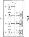
- FIG. 5 is a block diagram illustrating an electrical configuration of an information processing device 50 (computer) configured to carry out the production facility design process according to the first embodiment.
- the information processing device 50 is provided with a CPU (Central Processing Unit) 52 configured to manage the overall operation of the information processing device 50, a ROM (Read Only Memory) 54 in which various kinds of programs and various kinds of data are stored in advance, a RAM (Random Access Memory) 56 used as a work area or the like when the CPU 52 executes the various kinds of programs, and an HDD (Hard Disk Drive) 58 serving as a storage unit to store the various kinds of programs such as a program for carrying out the production facility design process, and the various kinds of data.
- a CPU Central Processing Unit
- ROM Read Only Memory
- RAM Random Access Memory
- HDD Hard Disk Drive
- the information processing device 50 is provided with an operation input unit 60 that is configured of a keyboard, mouse, and the like and receives the input of various kinds of operations, an image display unit 62 such as a liquid crystal display unit or the like configured to display various kinds of images, and an external interface 64 that is connected to other information processing devices or the like via communication lines and sends/receives various kinds of data to/from the other information processing devices or the like.
- an operation input unit 60 that is configured of a keyboard, mouse, and the like and receives the input of various kinds of operations
- an image display unit 62 such as a liquid crystal display unit or the like configured to display various kinds of images
- an external interface 64 that is connected to other information processing devices or the like via communication lines and sends/receives various kinds of data to/from the other information processing devices or the like.
- the CPU 52, ROM 54, RAM 56, HDD 58, operation input unit 60, image display unit 62, and external interface 64 are electrically connected to each other via a system bus 70.
- the CPU 52 can access the ROM 54, RAM 56, and HDD 58, grasp an operation state with respect to the operation input unit 60, display images on the image display unit 62, send/receive various kinds of data to/from the other information processing devices or the like via the external interface 64, and the like.
- FIG. 6 is a flowchart illustrating the flow of a program executed by the information processing device 50 when the production facility design process according to the first embodiment is carried out.
- step 102 a monthly production volume of the fuselage panels 12 is calculated based on the values inputted in step 100, and then the flow goes to step 108.
- the monthly production volume of the aircraft fuselage portions is 4.15 portions and the number of fuselage panels 12 needed per aircraft is 13 panels
- the monthly production volume of the fuselage panels 12 (number of fuselage panels processed) is 54 panels per month.
- step 104 the number of operating days per month of the production facility 10 and a daily operating time thereof are inputted.
- step 106 a monthly operating time of the production facility 10 is calculated based on the values inputted in step 104, and then the flow goes to step 108.
- the monthly operating time is 400 hours per month.
- production rate a time that can be used for riveting the one fuselage panel 12 (hereinafter called "production rate") is calculated in step 108.
- the production rate is calculated from the monthly production volume calculated in step 104 and the monthly operating time calculated in step 106.
- the stated production rate is what is called a takt time, which is the time each of the A/Rs 24 can use for riveting the fuselage panel 12.
- step 110 in consideration of a risk of the production facility 10 being stopped due to a trouble or the like, a value is calculated in which the production rate having been calculated in step 108 is multiplied by a predetermined value; then, the flow goes to step 114.
- the above-mentioned predetermined value is an estimated operating ratio of the production facility 10, and is 0.85, for example. Accordingly, in the case where the production rate is 444 minutes per panel, the value calculated in step 108 is 377 minutes per panel.
- This value represents a substantial operating time during which one single A/R 24 can rivet the fuselage panel 12, and is set as a set operating time in an A/R simulation.
- step 112 an average riveting time of each of the fuselage panel 12 is inputted; then, the flow goes to step 114. Note that the average riveting time is obtained in advance.
- step 114 the average riveting time inputted in step 112 is divided by the set operating time calculated in step 110, thereby calculating the minimum number of necessary A/Rs 24. Because the plurality of fuselage panels 12 having different shapes are transported to the production facility 10, calculating the minimum number of A/Rs 24 based on the average riveting time of the fuselage panel 12 makes it possible to appropriately determine the necessary number of A/Rs 24.
- the minimum number of A/Rs 24 may be calculated in step 114 using the production rate having been calculated in step 108 without executing step 110. In this case, the production rate is taken as the set operating time.
- the number of buffer areas 34 and the transport order of the fuselage panels 12 are determined by simulation using the minimum number of A/Rs 24 having been calculated in step 114.
- a buffer area number N B is set in step 200.
- the buffer area 34 is set adjacent to the work area 30, which is positioned on the most downstream side in the transport direction of the fuselage panel 12, on a further downstream side relative to the stated work area 30, for example.
- the transport order of the fuselage panels 12 is set in step 202.
- the transport order of the fuselage panels 12 may be set at random, or set based on a predetermined regulation (rule), for example.
- step 206 it is determined whether or not the A/Rs 24 have completed the riveting of the fuselage panels 12 within the set operating time in all the production processes (Takts).
- Takts the transport order of the fuselage panels 12 is determined so that the operating time of each A/R 24 will not exceed the set operating time.
- step 206 If an affirmative determination is given in step 206, the flow goes to step 208.
- step 206 if a negative determination is given in step 206, the flow goes to step 210.
- step 210 it is determined whether or not the A/R simulation has been carried out and finished in consideration of all the combinations of the transport orders of the fuselage panels 12; then, the flow goes to step 212 if the determination is affirmative. On the other hand, the flow goes to step 202 if the determination is negative, and another transport order, different from the transport orders of the fuselage panels 12 set in the past in the simulation, is set again; then, the A/R simulation is carried out again.
- step 212 When the setting in step 212 is completed, the flow goes to step 202, where the transport order of the fuselage panels 12 is set; then, the A/R simulation is carried out again in step 204.
- FIG. 7 to FIG. 9 illustrate an example of the transport order of the fuselage panels 12 in the case where a result of the A/R simulation is unsuccessful.
- the three A/Rs 24 are set and the one buffer area 34 is set on the downstream side of Pos. 3.
- FIG. 7 illustrates amounts of time (operating time) consumed in riveting the fuselage panels 12 (13 panels (fuselage panels A to M) as an example) by the respective A/Rs 24 at each Takt.
- the A/R3 rivets the fuselage panel J in the buffer area 34; however, the operating time calculated by the A/R simulation is 428 minutes, which exceeds 377 minutes as the substantial operating time (set operating time).
- FIG. 8 is a schematic view illustrating riveting times (necessary riveting times) needed for each of the fuselage panels A to M, calculated riveting times (actual riveting times), and differences in time (remaining work) between the necessary riveting times and the actual riveting times.
- FIG. 9 is a schematic view illustrating respective operating times of the A/R1 to A/R3. All the operating times of the A/R1 and A/R2 in the A/R simulation result are within the substantial operating time (377 minutes). On the other hand, the operating time of the A/R3 at Takt11 exceeds 377 minutes.
- FIG. 10 to FIG. 13 illustrate an example of the transport order of the fuselage panels 12 in the case where a result of the A/R simulation is successful, and FIG. 10 corresponds to FIG. 7 , FIG. 11 corresponds to FIG. 8 , and FIG. 12 corresponds to FIG. 9 .
- FIG. 13 is a schematic view illustrating: the fuselage panels 12 riveted in the work areas 30 (Pos. 1 to Pos. 3), and the buffer area 34 to which the A/Rs 24 respectively correspond; and a transport state of each of the fuselage panels 12.
- the A/R3 rivets the fuselage panel E in the buffer area 34 thereby completing the riveting of all the fuselage panels 12 within the set operating time.
- the A/R simulation may be carried out such that part of the riveting work by the A/R 24 on the upstream side, which is completed if attempted, is left incomplete on purpose and the A/R 24 on the downstream side carries out the remaining riveting work.
- the production facility 10 is provided with: the AGV 16 configured to transport the plurality of fuselage panels 12 of multiple types having different shapes in a mixed state on the predetermined transport path 14; the plurality of A/Rs 24 configured to rivet the fuselage panels 12 transported on the transport path 14; and the work areas 30 that are preset in the transport path 14 corresponding to the plurality of A/Rs 24 and represent ranges in which the A/Rs 24 can work to rivet the fuselage panels 12.
- the production facility 10 is further provided with the buffer area 34 preset adjacent to the work area 30 in the transport path 14 to which the A/R 24 corresponding to the adjacent work area 30 is moved so as to rivet the fuselage panel 12.
- the control device 32 of the production facility 10 performs the movement machining processing in which the A/R 24 which corresponds to the work area 30 adjacent to the buffer area 34 is moved to the buffer area 34 to rivet the fuselage panel 12 therein.
- the production facility 10 moves the A/R 24 being not used for riveting the fuselage panel 12 to the adjacent buffer area 34 so as to rivet the fuselage panel 12 in the buffer area 34, the operating ratio of the A/Rs 24 is increased and the fuselage panels 12 can be efficiently riveted even in the case where the plurality of fuselage panels 12 having different shapes are continuously riveted.
- the work area 30 corresponding to the broken-down A/R 24 may be set as a new buffer area 34, and the A/R 24 adjacent to the newly set buffer area 34 may move to the newly set buffer area 34 and rivet the fuselage panel 12 therein.
- the production facility design process as illustrated in FIG. 6 is carried out while setting the broken-down A/R 24 to be not used, and the transport order of the fuselage panels 12 is determined again.
- the production rate of the fuselage panels and the number of A/Rs 24 are set in accordance with the number of operational A/Rs 24, the processing (simulation) according to step 200 through step 212 is carried out to determine again the transport order of the fuselage panels 12, and the A/Rs 24 are controlled in accordance with the determined transport order.
- the buffer area number is set while taking the newly set buffer area 34 into consideration.
- the configuration of the production facility 10 according to the second embodiment is the same as the configuration of the production facility 10 according to the first embodiment illustrated in FIG. 1 , so the explanation thereof is omitted.
- the movement machining processing according to the second embodiment is a kind of processing in which the A/R 24 having no fuselage panel 12 to rivet in the work area 30 corresponding to the stated A/R 24 is moved to another adjacent work area 30 (the work area 30 where the A/R 24 is disposed) to rivet the fuselage panel 12.
- the fuselage panel 12 capable of being riveted by the plurality of A/Rs 24 is present in the work area 30 and no fuselage panel 12 to be riveted is present in another work area 30 adjacent to this work area 30, the A/R 24 corresponding to the above another work area 30 is moved to the adjacent work area 30, thereby riveting the fuselage panel 12 by the plurality of A/Rs 24.
- the fuselage panel 12 capable of being riveted by the plurality of A/Rs 24 refers to the fuselage panel 12, the riveting of which is not completed by a single A/R 24, such as the fuselage panel 12_b or 12_m.
- riveting the fuselage panel 12 by the plurality of A/Rs 24 means riveting the stated fuselage panel 12 by the two A/Rs 24 simultaneously, for example.
- the A/R 24 being not used for riveting the fuselage panel 12 is moved to the adjacent work area 30, whereby the plurality of A/Rs 24 cooperate with each other to rivet the one fuselage panel 12. Accordingly, the operating ratio of the A/Rs 24 is increased, and the fuselage panels 12 can be efficiently riveted even in the case where the plurality of fuselage panels 12 having different shapes are continuously riveted.
- FIG. 15 is a schematic view illustrating the operating states of the A/Rs 24 in the case of the simultaneous multiple A/R processing is not carried out
- FIG. 16 is a schematic view illustrating the operating states of the A/Rs 24 in the case of the simultaneous multiple A/R processing is carried out.
- lateral rows represent positions of the respective A/Rs 24, while longitudinal rows (Takt1 to Takt5 or Takt1 to Takt4) represent contents of the production processes carried out in the work areas 30 (Pos. 1 to Pos. 3), in other words, the passage of time.
- the three A/Rs 24 are provided in the production facility 10, and the small, large, and medium fuselage panels 12 are transported on the transport path 14 in this order.
- the large fuselage panel 12_b is transported and stopped in Pos. 1, and one third of the total length of the fuselage panel 12_b is riveted by the A/R1 within the stoppage time.
- the fuselage panel 12_s from Pos. 1 is transported and stopped in Pos. 2, the A/R2 does not operate because the riveting thereof has already been completed.
- the medium fuselage panel 12_m is transported and stopped in Pos. 1, and half of the total length of the fuselage panel 12_m is riveted by the A/R1 within the stoppage time.
- the fuselage panel 12_b from Pos. 1 is transported and stopped in Pos. 2, and a subsequent one third of the fuselage panel 12_b is riveted by the A/R2.
- the fuselage panel 12_s from Pos. 2 is transported and stopped in Pos. 3, the A/R3 does not operate because the riveting thereof has already been completed.
- the fuselage panel 12_m from Pos. 1 is transported and stopped in Pos. 2, and the remaining half of the fuselage panel 12_m is riveted by the A/R2, thereby completing the riveting of the fuselage panel 12_m.
- the fuselage panel 12_b from Pos. 2 is transported and stopped in Pos. 3, and the remaining one third of the fuselage panel 12_b is riveted by the A/R3, thereby completing the riveting of the fuselage panel 12_b.
- the operating ratio of the A/Rs 24 is 67%.
- FIG. 16 indicates a case in which the two A/Rs 24 carry out the simultaneous multiple A/R processing, and like in FIG. 15 , the small, large, and medium fuselage panels 12 are transported on the transport path 14 in this order.
- the large fuselage panel 12_b is transported and stopped in Pos. 1, and one third of the fuselage panel 12_b on the upstream side in a transport direction thereof is riveted by the A/R1 within the stoppage time.
- the fuselage panel 12_s from Pos. 1 is transported and stopped in Pos. 2
- the fuselage panel 12 to be riveted in Pos. 2 by the A/R2 is not present because the riveting of the fuselage panel 12_s has already been completed.
- the A/R2 moves to Pos. 1 to rivet one third of the fuselage panel 12_b on a downstream side in the transport direction thereof.
- the medium fuselage panel 12_m is transported and stopped in Pos. 1, and half of the total length of the fuselage panel 12_m is riveted by the A/R1 within the stoppage time. Further, the fuselage panel 12_b from Pos. 1 is transported and stopped in Pos. 2, and the remaining one third of the fuselage panel 12_b (one third of the total length in the central portion) is riveted by the A/R2, thereby completing the riveting of the fuselage panel 12_b.
- the one fuselage panel 12 is riveted by the plurality of A/Rs 24, the operating ratio of the A/Rs 24 is increased, and the fuselage panels 12 can be efficiently riveted even in the case where the plurality of fuselage panels 12 having different shapes are continuously riveted.
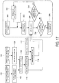
- FIG. 17 is a flowchart illustrating the flow of a program executed by the information processing device 50 when the production facility design process according to the second embodiment is carried out. Because step 100 through step 114 in FIG. 17 are the same as those in FIG. 6 , description thereof is omitted herein.
- the production facility design process according to the second embodiment determines the transport order of the fuselage panels 12 of multiple types and the number of A/Rs 24 configured to move to another work area 30 and rivet the fuselage panel 12 (hereinafter called "cooperation number").
- step 304 the A/R simulation is carried out based on the set operating time calculated in step 110, the number of A/Rs 24 determined in step 114, the cooperation number N AR set in step 300, and the transport order of the fuselage panels 12 set in step 302.
- step 306 it is determined whether or not the A/Rs 24 have completed the riveting of the fuselage panels 12 within the set operating time in all the production processes (Takt). If an affirmative determination is given in step 306, the flow goes to step 308.
- step 308 based on the recognition that the production line is successfully established with the set cooperation number N AR as well as the set transport order of the fuselage panels 12, the successful A/R simulation result is stored in the HDD 58.
- step 306 the flow goes to step 310.
- step 310 it is determined whether or not the A/R simulation has been carried out and finished in consideration of all the combinations of the transport orders of the fuselage panels 12; then, the flow goes to step 312 if the determination is affirmative. On the other hand, the flow goes to step 302 if the determination is negative, and a transport order, different from the transport orders of the fuselage panels 12 set in the past in the simulation, is set again; then, the A/R simulation is carried out again.
- the A/R 24 on the upstream side of the A/R having been set as the cooperation A/R is newly set as a cooperation A/R.
- step 312 When the setting in step 312 is finished, the flow goes to step 302, where the transport order of the fuselage panels 12 is set again; then, the A/R simulation is carried out again.
- FIG. 18 to FIG. 20 illustrate an example of the transport order of the fuselage panels 12 in the case where a result of the A/R simulation is unsuccessful.
- the three A/Rs 24 are set, where the A/R2 can move to Pos. 1 and the A/R3 can move to Pos. 2.
- FIG. 18 illustrates amounts of time (operating time) consumed in riveting the fuselage panels 12 (13 panels (fuselage panels A to M) as an example) by the respective A/Rs 24 at each Takt.
- the A/R3 rivets the fuselage panel G in Pos. 3; however, the operating time calculated by the A/R simulation is 402 minutes, which exceeds 377 minutes as the substantial operating time (set operating time).
- FIG. 19 is a schematic view illustrating riveting times (necessary riveting times) needed for each of the fuselage panels A to M, calculated riveting times (actual riveting times), and differences in time (remaining work) between the necessary riveting times and the actual riveting times.
- FIG. 20 is a schematic view illustrating respective operating times of the A/R1 to A/R3. All the operating times of the A/R1 and A/R2 in the A/R simulation result are within the substantial operating time (377 minutes). On the other hand, the operating time of the A/R3 at Takt9 exceeds 377 minutes.
- FIG. 21 to FIG. 23 illustrate an example of the transport order of the fuselage panels 12 in the case where a result of the A/R simulation is successful
- FIG. 21 corresponds to FIG. 18
- FIG. 22 corresponds to FIG. 19
- FIG. 23 corresponds to FIG. 20 .
- the operating times of all the A/Rs 24 are within the substantial operating time (377 minutes).
- the simultaneous multiple A/R processing according to the second embodiment moves the A/R 24 being not used for riveting the fuselage panel 12 to another adjacent work area 30, whereby the plurality of A/Rs 24 cooperate with each other to rivet the one fuselage panel 12. Accordingly, with the simultaneous multiple A/R processing, the operating ratio of the A/Rs 24 is increased, and the fuselage panels 12 can be efficiently riveted even in the case where the plurality of fuselage panels 12 having different shapes are continuously riveted.
- the adjacent A/R 24 may move to the work area 30 corresponding to the broken-down A/R 24 and rivet the fuselage panel 12 therein in place of the broken-down A/R 24.
- the A/R 24 having moved returns, after having finished the riveting in the work area 30 to which the A/R 24 moved, to the work area 30 corresponding to the stated A/R 24 and rivets the fuselage panel 12 therein again.
- the production facility design process as illustrated in FIG. 17 is carried out while setting the broken-down A/R 24 to be not used, and the transport order of the fuselage panels 12 is determined again.
- the production rate of the fuselage panels and the number of A/Rs 24 are set in accordance with the number of operational A/Rs 24, the processing (simulation) according to step 300 through step 312 is carried out to determine the transport order of the fuselage panels 12 again, and the A/Rs 24 are controlled in accordance with the determined transport order.
- the present invention is not limited thereto and another mode is also permissible.
- all the plurality of processing devices 24 may not be of the same type; the processing devices 24 of different types may be mixed, the processing device 24 that does not contribute to the movement machining processing may be included, or processing performed by manual operation of a worker may be included between the processing devices 24.
Landscapes
- Engineering & Computer Science (AREA)
- Business, Economics & Management (AREA)
- Manufacturing & Machinery (AREA)
- Physics & Mathematics (AREA)
- General Physics & Mathematics (AREA)
- Quality & Reliability (AREA)
- Entrepreneurship & Innovation (AREA)
- Human Resources & Organizations (AREA)
- Strategic Management (AREA)
- Economics (AREA)
- Automation & Control Theory (AREA)
- General Engineering & Computer Science (AREA)
- Operations Research (AREA)
- Tourism & Hospitality (AREA)
- Marketing (AREA)
- Theoretical Computer Science (AREA)
- General Business, Economics & Management (AREA)
- Mechanical Engineering (AREA)
- Transportation (AREA)
- Aviation & Aerospace Engineering (AREA)
- Development Economics (AREA)
- Educational Administration (AREA)
- Game Theory and Decision Science (AREA)
- General Factory Administration (AREA)
- Automatic Assembly (AREA)
- Management, Administration, Business Operations System, And Electronic Commerce (AREA)
Applications Claiming Priority (2)
| Application Number | Priority Date | Filing Date | Title |
|---|---|---|---|
| JP2015162680A JP6563274B2 (ja) | 2015-08-20 | 2015-08-20 | 生産設備、生産設備の設計方法、並びに生産設備の制御方法及び製造方法 |
| PCT/JP2016/070605 WO2017029912A1 (fr) | 2015-08-20 | 2016-07-12 | Installation de production, procédé de conception d'installation de production, procédé de commande d'installation de production et procédé de fabrication |
Publications (2)
| Publication Number | Publication Date |
|---|---|
| EP3272454A1 true EP3272454A1 (fr) | 2018-01-24 |
| EP3272454A4 EP3272454A4 (fr) | 2018-12-26 |
Family
ID=58050788
Family Applications (1)
| Application Number | Title | Priority Date | Filing Date |
|---|---|---|---|
| EP16836903.1A Withdrawn EP3272454A4 (fr) | 2015-08-20 | 2016-07-12 | Installation de production, procédé de conception d'installation de production, procédé de commande d'installation de production et procédé de fabrication |
Country Status (7)
| Country | Link |
|---|---|
| US (1) | US10654138B2 (fr) |
| EP (1) | EP3272454A4 (fr) |
| JP (1) | JP6563274B2 (fr) |
| CN (1) | CN107921591A (fr) |
| BR (1) | BR112017022995A2 (fr) |
| CA (1) | CA2983725C (fr) |
| WO (1) | WO2017029912A1 (fr) |
Cited By (5)
| Publication number | Priority date | Publication date | Assignee | Title |
|---|---|---|---|---|
| CN114516420A (zh) * | 2020-11-18 | 2022-05-20 | 波音公司 | 机体的移动流水线组装 |
| EP4000904A1 (fr) * | 2020-11-18 | 2022-05-25 | The Boeing Company | Ensemble de ligne mobile de cellules |
| EP4001094A1 (fr) | 2020-11-18 | 2022-05-25 | The Boeing Company | Ensemble aéronef formé de sections de demi-tonneau assemblées et son procédé d'assemblage |
| NL2027401B1 (en) * | 2021-01-26 | 2022-08-17 | Boeing Co | Aircraft assembly formed of mating half barrel sections and the method of assembling the same |
| US11801576B2 (en) | 2020-11-18 | 2023-10-31 | The Boeing Company | Aircraft assembly formed of mating half barrel sections and the method of assembling the same |
Families Citing this family (6)
| Publication number | Priority date | Publication date | Assignee | Title |
|---|---|---|---|---|
| JP2020035385A (ja) * | 2018-08-31 | 2020-03-05 | 三菱重工業株式会社 | スケジュール作成装置、スケジュール作成方法及びプログラム |
| CN112051806B (zh) * | 2019-09-10 | 2022-01-28 | 南京邮电大学 | 一种随机故障下往复式轨道中的rgv智能调度方法 |
| EP4001125B1 (fr) * | 2020-11-18 | 2025-10-01 | The Boeing Company | Systèmes et procédés de fabrication d'aéronef |
| EP4002034B1 (fr) | 2020-11-18 | 2024-08-14 | The Boeing Company | Systèmes et procédés de pulsation fractionnée de composants d'aéronefs et conception de systèmes de fabrication les utilisant |
| US11827380B2 (en) * | 2021-01-26 | 2023-11-28 | The Boeing Company | System and method for positioning a sub-assembly for installation |
| CN119278417A (zh) * | 2022-06-01 | 2025-01-07 | 三菱电机株式会社 | 生产系统、生产线分析方法、学习装置、推理装置、学习完毕模型以及学习完毕模型的生成方法 |
Family Cites Families (29)
| Publication number | Priority date | Publication date | Assignee | Title |
|---|---|---|---|---|
| US6708385B1 (en) * | 1954-07-28 | 2004-03-23 | Lemelson Medical, Education And Research Foundation, Lp | Flexible manufacturing systems and methods |
| US6076652A (en) * | 1971-04-16 | 2000-06-20 | Texas Instruments Incorporated | Assembly line system and apparatus controlling transfer of a workpiece |
| US4683651A (en) * | 1984-07-09 | 1987-08-04 | Mazda Motor Corporation | Vehicle assembly line |
| JPH06163293A (ja) | 1992-11-19 | 1994-06-10 | Mitsubishi Electric Corp | 生産管理方法 |
| US6104965A (en) * | 1997-05-01 | 2000-08-15 | Motorola, Inc. | Control of workstations in assembly lines |
| JP2001075624A (ja) * | 1999-07-01 | 2001-03-23 | Mori Seiki Co Ltd | Nc工作機械のツールパスデータ生成装置及びこれを備えた数値制御装置 |
| US6801821B2 (en) * | 1999-08-03 | 2004-10-05 | Honda Canada Incorporated | Assembly line control system |
| JP3844653B2 (ja) | 1999-12-28 | 2006-11-15 | 本田技研工業株式会社 | 車体組立方法及び車体組立ライン |
| US6554119B2 (en) * | 2000-02-07 | 2003-04-29 | Progressive Tool & Industries Co. | Flexible automotive assembly line and method |
| US6823230B1 (en) * | 2000-09-07 | 2004-11-23 | Honeywell International Inc. | Tool path planning process for component by layered manufacture |
| GB0112559D0 (en) * | 2000-09-14 | 2001-07-11 | Bae Systems Plc | A method and control system for generating machine tool control data |
| DE10102758A1 (de) * | 2001-01-23 | 2002-07-25 | Volkswagen Ag | Vorrichtung zur Bearbeitung von Bauteilen |
| JP2002239848A (ja) | 2001-02-13 | 2002-08-28 | Auto Network Gijutsu Kenkyusho:Kk | 小型ワークの組み立てライン |
| US6898484B2 (en) * | 2002-05-01 | 2005-05-24 | Dorothy Lemelson | Robotic manufacturing and assembly with relative radio positioning using radio based location determination |
| JP2004050918A (ja) | 2002-07-18 | 2004-02-19 | Daihatsu Motor Co Ltd | 組立待機車列レーンの車両投入抜取指示システム |
| JP4557986B2 (ja) * | 2004-11-24 | 2010-10-06 | 株式会社日立国際電気 | 基板処理装置及び半導体デバイスの製造方法 |
| US7979293B2 (en) * | 2005-09-29 | 2011-07-12 | GM Global Technology Operations LLC | System and method for production system operations timing |
| US8312611B2 (en) | 2008-08-08 | 2012-11-20 | Honda Motor Co., Ltd. | Assembling method and apparatus for assembly, and assembling method and apparatus for workpiece |
| JP2010042456A (ja) | 2008-08-08 | 2010-02-25 | Honda Motor Co Ltd | ワークの組立方法及びその装置 |
| US20100217437A1 (en) | 2009-02-24 | 2010-08-26 | Branko Sarh | Autonomous robotic assembly system |
| WO2011105641A1 (fr) | 2010-02-25 | 2011-09-01 | (주)에이시에스 | Système d'automatisation de la configuration de ressources pour la relocalisation d'installations de production et procédé associé |
| JP5421172B2 (ja) | 2010-03-31 | 2014-02-19 | 日立建機株式会社 | 溶接ライン |
| US8489224B2 (en) * | 2011-02-28 | 2013-07-16 | Solidcam Ltd. | Computerized tool path generation |
| US9090357B2 (en) | 2011-12-15 | 2015-07-28 | The Boeing Company | Method of assembling panelized aircraft fuselages |
| US10055512B2 (en) * | 2012-07-16 | 2018-08-21 | Omc2 Llc | System and method for CNC machines and software |
| CN104463394A (zh) * | 2013-09-18 | 2015-03-25 | Sap欧洲公司 | 生产资源管理 |
| JP2015093354A (ja) | 2013-11-12 | 2015-05-18 | 富士通株式会社 | 台車 |
| JP6521565B2 (ja) * | 2014-01-20 | 2019-05-29 | Dmg森精機株式会社 | 省電力を考慮したncプログラム生成装置 |
| US9014902B1 (en) * | 2014-02-21 | 2015-04-21 | Jervis B. Webb Company | Method of material handling with automatic guided vehicles |
-
2015
- 2015-08-20 JP JP2015162680A patent/JP6563274B2/ja active Active
-
2016
- 2016-07-12 BR BR112017022995-1A patent/BR112017022995A2/pt not_active IP Right Cessation
- 2016-07-12 CN CN201680024540.0A patent/CN107921591A/zh active Pending
- 2016-07-12 CA CA2983725A patent/CA2983725C/fr not_active Expired - Fee Related
- 2016-07-12 US US15/569,984 patent/US10654138B2/en active Active
- 2016-07-12 EP EP16836903.1A patent/EP3272454A4/fr not_active Withdrawn
- 2016-07-12 WO PCT/JP2016/070605 patent/WO2017029912A1/fr not_active Ceased
Cited By (6)
| Publication number | Priority date | Publication date | Assignee | Title |
|---|---|---|---|---|
| CN114516420A (zh) * | 2020-11-18 | 2022-05-20 | 波音公司 | 机体的移动流水线组装 |
| EP4000904A1 (fr) * | 2020-11-18 | 2022-05-25 | The Boeing Company | Ensemble de ligne mobile de cellules |
| EP4001094A1 (fr) | 2020-11-18 | 2022-05-25 | The Boeing Company | Ensemble aéronef formé de sections de demi-tonneau assemblées et son procédé d'assemblage |
| US11724346B2 (en) | 2020-11-18 | 2023-08-15 | The Boeing Company | Moving line assembly of airframes |
| US11801576B2 (en) | 2020-11-18 | 2023-10-31 | The Boeing Company | Aircraft assembly formed of mating half barrel sections and the method of assembling the same |
| NL2027401B1 (en) * | 2021-01-26 | 2022-08-17 | Boeing Co | Aircraft assembly formed of mating half barrel sections and the method of assembling the same |
Also Published As
| Publication number | Publication date |
|---|---|
| BR112017022995A2 (pt) | 2018-07-24 |
| JP6563274B2 (ja) | 2019-08-21 |
| US10654138B2 (en) | 2020-05-19 |
| JP2017039187A (ja) | 2017-02-23 |
| CA2983725A1 (fr) | 2017-02-23 |
| WO2017029912A1 (fr) | 2017-02-23 |
| CN107921591A (zh) | 2018-04-17 |
| CA2983725C (fr) | 2020-11-10 |
| EP3272454A4 (fr) | 2018-12-26 |
| US20180104778A1 (en) | 2018-04-19 |
Similar Documents
| Publication | Publication Date | Title |
|---|---|---|
| US10654138B2 (en) | Production facility, production facility design method, production facility control method, and manufacturing method | |
| EP3445526B1 (fr) | Installation de fabrication et procédé de fabrication | |
| EP3259096B1 (fr) | Installation et procédé de fabrication | |
| EP3703902B1 (fr) | Système de transport et procédé de transport simultané de pièces et de monteurs | |
| CN109976320B (zh) | 一种基于时间窗在线修正的多agv路径规划方法 | |
| DE102013000569B4 (de) | Fertigungsanlage zur Serienfertigung von Kraftfahrzeugen | |
| DE102019008205A1 (de) | Produktionsplanungsvorrichtung | |
| EP2392981B1 (fr) | Procédé de commande d'une voie de fabrication cadencée | |
| DE102016204392A1 (de) | System und Verfahren zur Produktionsplanung | |
| DE102016010983A1 (de) | Verfahren zum Montieren eines Objekts | |
| DE102022120455A1 (de) | Teile-zufuhrsystem und verfahren zum betreiben eines teile-zufuhrsystems | |
| WO2022188929A1 (fr) | Procédé de commande de véhicules de transport et système de transport | |
| EP4002034B1 (fr) | Systèmes et procédés de pulsation fractionnée de composants d'aéronefs et conception de systèmes de fabrication les utilisant | |
| US20250153752A1 (en) | Method of departure management of automated guided vehicle and departure management system of automated guided vehicle for performing the same | |
| DE102010006093A1 (de) | Verfahren zum Aufbau oder zur Aktualisierung von Routingtabellen für ein modulares Fördersystem und modulares Fördersystem | |
| US11593730B2 (en) | Schedule creation device, schedule creation method, and program | |
| DE102019203290B3 (de) | Verfahren zum Montieren von Bauteilen | |
| AU2023321641B2 (en) | Method and system for transporting items | |
| EP4465142B1 (fr) | Classificateur à blocage préventif | |
| Hirogaki et al. | Autonomous conveyance control of AGV based on knowledge of taxi transportation rules | |
| JPH04303204A (ja) | 生産計画システム | |
| EP1729196B1 (fr) | Système de commande pour véhicules conduits manuellement | |
| EP4001125B1 (fr) | Systèmes et procédés de fabrication d'aéronef | |
| Raymond | Applicability of Toyota production system to commercial airplane manufacturing | |
| CN120146751A (zh) | 一种生产出库管理方法、系统及存储介质 |
Legal Events
| Date | Code | Title | Description |
|---|---|---|---|
| STAA | Information on the status of an ep patent application or granted ep patent |
Free format text: STATUS: THE INTERNATIONAL PUBLICATION HAS BEEN MADE |
|
| PUAI | Public reference made under article 153(3) epc to a published international application that has entered the european phase |
Free format text: ORIGINAL CODE: 0009012 |
|
| STAA | Information on the status of an ep patent application or granted ep patent |
Free format text: STATUS: REQUEST FOR EXAMINATION WAS MADE |
|
| 17P | Request for examination filed |
Effective date: 20171017 |
|
| AK | Designated contracting states |
Kind code of ref document: A1 Designated state(s): AL AT BE BG CH CY CZ DE DK EE ES FI FR GB GR HR HU IE IS IT LI LT LU LV MC MK MT NL NO PL PT RO RS SE SI SK SM TR |
|
| AX | Request for extension of the european patent |
Extension state: BA ME |
|
| RIC1 | Information provided on ipc code assigned before grant |
Ipc: G05B 19/418 20060101ALI20180620BHEP Ipc: B64F 5/00 20170101ALI20180620BHEP Ipc: B23P 21/00 20060101AFI20180620BHEP |
|
| RIC1 | Information provided on ipc code assigned before grant |
Ipc: B64F 5/00 20170101ALI20180719BHEP Ipc: B23P 21/00 20060101AFI20180719BHEP Ipc: G05B 19/418 20060101ALI20180719BHEP |
|
| DAV | Request for validation of the european patent (deleted) | ||
| DAX | Request for extension of the european patent (deleted) | ||
| A4 | Supplementary search report drawn up and despatched |
Effective date: 20181127 |
|
| RIC1 | Information provided on ipc code assigned before grant |
Ipc: G06Q 10/06 20120101ALI20181121BHEP Ipc: B64F 5/00 20170101ALI20181121BHEP Ipc: G05B 19/418 20060101ALI20181121BHEP Ipc: B23P 21/00 20060101AFI20181121BHEP |
|
| STAA | Information on the status of an ep patent application or granted ep patent |
Free format text: STATUS: EXAMINATION IS IN PROGRESS |
|
| 17Q | First examination report despatched |
Effective date: 20201014 |
|
| STAA | Information on the status of an ep patent application or granted ep patent |
Free format text: STATUS: THE APPLICATION IS DEEMED TO BE WITHDRAWN |
|
| 18D | Application deemed to be withdrawn |
Effective date: 20220201 |