EP3272637B1 - Aus verbundstoffmaterial geformte zurrstange und herstellungsverfahren dafür - Google Patents
Aus verbundstoffmaterial geformte zurrstange und herstellungsverfahren dafür Download PDFInfo
- Publication number
- EP3272637B1 EP3272637B1 EP17767978.4A EP17767978A EP3272637B1 EP 3272637 B1 EP3272637 B1 EP 3272637B1 EP 17767978 A EP17767978 A EP 17767978A EP 3272637 B1 EP3272637 B1 EP 3272637B1
- Authority
- EP
- European Patent Office
- Prior art keywords
- lashing
- continuous fibers
- thimbles
- type
- lashing bar
- Prior art date
- Legal status (The legal status is an assumption and is not a legal conclusion. Google has not performed a legal analysis and makes no representation as to the accuracy of the status listed.)
- Active
Links
Images





Classifications
-
- F—MECHANICAL ENGINEERING; LIGHTING; HEATING; WEAPONS; BLASTING
- F16—ENGINEERING ELEMENTS AND UNITS; GENERAL MEASURES FOR PRODUCING AND MAINTAINING EFFECTIVE FUNCTIONING OF MACHINES OR INSTALLATIONS; THERMAL INSULATION IN GENERAL
- F16C—SHAFTS; FLEXIBLE SHAFTS; ELEMENTS OR CRANKSHAFT MECHANISMS; ROTARY BODIES OTHER THAN GEARING ELEMENTS; BEARINGS
- F16C7/00—Connecting-rods or like links pivoted at both ends; Construction of connecting-rod heads
- F16C7/02—Constructions of connecting-rods with constant length
- F16C7/026—Constructions of connecting-rods with constant length made of fibre reinforced resin
-
- B—PERFORMING OPERATIONS; TRANSPORTING
- B29—WORKING OF PLASTICS; WORKING OF SUBSTANCES IN A PLASTIC STATE IN GENERAL
- B29C—SHAPING OR JOINING OF PLASTICS; SHAPING OF MATERIAL IN A PLASTIC STATE, NOT OTHERWISE PROVIDED FOR; AFTER-TREATMENT OF THE SHAPED PRODUCTS, e.g. REPAIRING
- B29C70/00—Shaping composites, i.e. plastics material comprising reinforcements, fillers or preformed parts, e.g. inserts
- B29C70/04—Shaping composites, i.e. plastics material comprising reinforcements, fillers or preformed parts, e.g. inserts comprising reinforcements only, e.g. self-reinforcing plastics
- B29C70/28—Shaping operations therefor
- B29C70/30—Shaping by lay-up, i.e. applying fibres, tape or broadsheet on a mould, former or core; Shaping by spray-up, i.e. spraying of fibres on a mould, former or core
-
- B—PERFORMING OPERATIONS; TRANSPORTING
- B60—VEHICLES IN GENERAL
- B60P—VEHICLES ADAPTED FOR LOAD TRANSPORTATION OR TO TRANSPORT, TO CARRY, OR TO COMPRISE SPECIAL LOADS OR OBJECTS
- B60P7/00—Securing or covering of load on vehicles
- B60P7/06—Securing of load
-
- B—PERFORMING OPERATIONS; TRANSPORTING
- B63—SHIPS OR OTHER WATERBORNE VESSELS; RELATED EQUIPMENT
- B63B—SHIPS OR OTHER WATERBORNE VESSELS; EQUIPMENT FOR SHIPPING
- B63B25/00—Load-accommodating arrangements, e.g. stowing, trimming; Vessels characterised thereby
- B63B25/24—Means for preventing unwanted cargo movement, e.g. dunnage
-
- B—PERFORMING OPERATIONS; TRANSPORTING
- B63—SHIPS OR OTHER WATERBORNE VESSELS; RELATED EQUIPMENT
- B63B—SHIPS OR OTHER WATERBORNE VESSELS; EQUIPMENT FOR SHIPPING
- B63B25/00—Load-accommodating arrangements, e.g. stowing, trimming; Vessels characterised thereby
- B63B25/28—Load-accommodating arrangements, e.g. stowing, trimming; Vessels characterised thereby for deck loads
-
- B—PERFORMING OPERATIONS; TRANSPORTING
- B63—SHIPS OR OTHER WATERBORNE VESSELS; RELATED EQUIPMENT
- B63B—SHIPS OR OTHER WATERBORNE VESSELS; EQUIPMENT FOR SHIPPING
- B63B25/00—Load-accommodating arrangements, e.g. stowing, trimming; Vessels characterised thereby
- B63B25/28—Load-accommodating arrangements, e.g. stowing, trimming; Vessels characterised thereby for deck loads
- B63B2025/285—Means for securing deck containers against unwanted movements
-
- B—PERFORMING OPERATIONS; TRANSPORTING
- B63—SHIPS OR OTHER WATERBORNE VESSELS; RELATED EQUIPMENT
- B63B—SHIPS OR OTHER WATERBORNE VESSELS; EQUIPMENT FOR SHIPPING
- B63B2231/00—Material used for some parts or elements, or for particular purposes
-
- B—PERFORMING OPERATIONS; TRANSPORTING
- B63—SHIPS OR OTHER WATERBORNE VESSELS; RELATED EQUIPMENT
- B63B—SHIPS OR OTHER WATERBORNE VESSELS; EQUIPMENT FOR SHIPPING
- B63B2231/00—Material used for some parts or elements, or for particular purposes
- B63B2231/02—Metallic materials
Definitions
- the present invention relates to the equipment used for the lashing of containers. More specifically, the invention relates to a lashing bar made of a composite material formed through the filament winding process to provide light weight and capacity to withstand high tensile loads, and a method of manufacturing the same.
- on-deck containers refer to the boxes used for the efficient and cost-saving storage and transport of cargo.
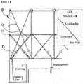
- FIG. 1 shows the conventional container lashing equipment that is commonly used now.
- the conventional containers (10) are clamped together using Twistlocks (11), which fasten the upper and lower tiers of the containers (10), and then lashing bars (13) and turnbuckles (15) are secured on deck with a crisscross lashing arrangement to reinforce the strength to withstand inclined and horizontal loads.
- Lashing bars are generally used on container ships to prevent containers from shifting and tilting during transportation at sea, and they connect the corner fittings and turnbuckles of containers.
- the eye type lashing bar in FIG. 2a comprises a hook-shaped coupling member through which one end of the bar is secured to a container, and an oval coupling member on the other end.
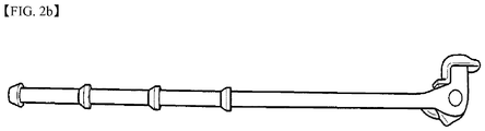
- the knob type lashing bar in FIG. 2b comprises a hook-shaped coupling member through which one end of the bar is secured to a container, and several stoppers on the other end to allow for length adjustments.
- a ship at sea moves in several degrees of motion, such as roll, pitch, and heave, and is affected by accelerations along the x, y, and z axes relative to different motions.
- Such acceleration causes a force on containers, which acts as a lashing force.
- Lashing bars are therefore subject to strict control in accordance with marine safety control regulations so that containers are secured on deck with adequate strength higher than the design limit to withstand roll, pitch, and high winds while the ship moves at sea, and only those products whose performance has been tested by supervisory authorities are permitted to be used to meet the aforementioned standard.
- lashing bars are made of high tensile strength alloy steels including SCR4, SCM4, and SNCM8.
- SCR4, SCM4, and SNCM8 high tensile strength alloy steels
- These products cause fatigue in operators, as well as accidents during transportation, installation, and dismantling, resulting in such problems as reduced efficiency and avoidance of work.
- DE 10 2006 060469 and DE 10 2007 015909 are examples of known lashing bars.
- the present invention provides a lashing bar made of a composite material comprising a bar-shaped central portion encased in a composite material through the winding of continuous fibers around the outer circumference of a metal cylindrical core which constitutes the core of the central portion; an oval coupling portion formed at one end of the aforementioned bar-shaped central portion and having wound continuous fibers attached to the holes of hook-type thimbles made from metal; and a hook-shaped coupling portion formed at the other end of the aforementioned bar-shaped central portion and having wound continuous fibers attached to the holes of two ring-type thimbles made from metal.
- the invention also provides a method of manufacturing lashing bars of a composite material comprising (1) a step in which a forming mold for the aforementioned lashing bar is assembled and loaded onto a filament winding machine; (2) a step in which continuous fibers are wound around the outer circumference of the aforementioned loaded lashing bar forming mold through the filament winding technique; and (3) a step in which the filament wound composite product is cured to form a lashing bar.
- An advantage of the present invention providing a lashing bar and a method of manufacturing the same is that it enables the manufacture of container lashing bars with light weight and capacity to withstand high tensile loads by forming a composite material through filament winding with continuous fibers including glass, carbon, and aramid fibers, which provide four to six times the tensile strength of high-tensile special steels at a specific gravity 25 to 35% lower than that of special steels, and by providing metal parts in certain areas where loads are concentrated.
- a lashing bar manufactured through the invention offers the advantages of maximizing efficiency during transportation and installation by radically lowering weight to 30 to 50% of the average weight of conventional metal lashing bars, thereby reducing accident rates and resolving the problem of work avoidance, and of allowing semi-permanent use by utilizing the corrosion resistance of the composite material, thereby solving the problem of limited service life for conventional metal products due to corrosion.
- FIG. 3 is a process flow chart to describe a method of manufacturing a lashing bar of a composite material according to the present invention
- FIG. 4 is a part drawing used in the manufacturing method of FIG. 3
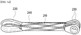
- FIG. 5a to 5c show the process of winding continuous fibers through the filament winding technique used in the manufacturing method of FIG. 3
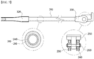
- FIG. 6 and 7 show the lashing bar made of a composite material according to the invention.
- a method of manufacturing a lashing bar made of a composite material according to the present invention with reference to FIG. 3 is described as the step in which the prepared parts are assembled as shown in FIG. 4 and then loaded onto the filament winding machine (step 110).
- the prepared parts consist of a cylindrical core (210), hook-type thimbles (220), and two ring-type thimbles (230).
- the said cylindrical core (210) constitutes the core of the center portion and a metal pipe thick enough to resist bending when tension is applied during the winding of continuous fibers.
- the aforementioned thimbles (220, 230) are made from metal and serve as a framework for the winding of continuous fibers during the lashing bar manufacturing process and later constitute the coupling portion of a lashing bar that can be coupled to the hooks of a container and put on other rings.
- the parts thus assembled are loaded onto the filament winding machine as the lashing bar forming mold (200) and then help wind the continuous fibers (240) according to the filament winding program (step 120).
- the filament winding process is a fabrication technique by which the continuous filaments of fiber-reinforced plastic (FRP) are wound around and attached onto the surface of a mandrel through the application of tension, heated and cured, and then removed from the mandrel.
- the technique is used in the manufacture of rotationally symmetrical structures such as cylindrical or spherical pressure vessels, tanks, and pipes.
- the aforementioned filament winding technique is applied to the alignment of the continuous fibers forming a composite material in the lashing bar forming mold (200) assembled with the central portion core (210) and the thimbles on both ends (220, 230).
- the most effective method of transmitting lengthwise tensile strength is the sub-step of 1 by which to align the continuous fibers (240) passed through the holes of the hook-type thimbles (220) lengthwise (0 degrees).
- the continuous fibers (240) are aligned at degrees not exceeding ⁇ 15 to minimize the loss of tensile strength while the fibers are evenly distributed lengthwise along the cylindrical core (210).
- the continuous fibers (240) are aligned at ⁇ 40 to ⁇ 50 degrees to efficiently and adequately resist torsion loads that arise during installation.
- the winding of the continuous fibers (240) is to be repeated a certain number of times until the fibers are attached through the application of tension to the surface of the lashing bar forming mold (20).
- FIG. 5c shows a front view of the alignment of the continuous fibers.
- the types of the continuous fibers (240) to be applied in the present invention are glass, carbon, aramid, and polyethylene fibers.
- the tensile strengths of these fibers are generally higher than the tensile strength of high-tensile steels as shown in Table 1 below.
- Table 1 Classification Specific gravity Tensile strength (Mpa) Tensile elasticity (Gpa) Remarks High-tensile steel 7.8 550-950 200 Glass fiber 2.6 3,100-3,800 75-78 Carbon fiber 1.8 4,200-6,100 230-300 Aramid fiber 1.4 3,600 41-186 Polyethylene fiber 1.0 2,200-3,500 89-116
- the product While the continuous fibers (240) forming the aforementioned composite material are wound and attached by tension to the surface of the lashing bar forming mold (200), the product is mounted in a rotating curing oven and then cured (step 130). Then, the product is transferred to the stripping/finishing process by which sharp edges on the surface are removed in a finishing workshop equipped with a dust collector (step 140).
- the stripped/finished product is tested for its capacity to withstand tensile and torsion loads (step 150) and, when the product meets its requirements, it is packaged and shipped (step 160).
- a lashing bar made of a composite material manufactured and finished through the aforementioned processes according to the present invention will have the shape shown in FIG. 6 and 7 .
- the lashing bar made of a composite material provided in the present invention (300) is an eye type comprising a bar-shaped central portion (310), an oval coupling portion on one end (320) and a hook coupling portion on the opposite end (330).
- the oval coupling portion (320) comprises a hook-type metal thimble (220) featuring a hole into which the continuous fiber composite material (240) is integrated.
- the hook coupling portion (330) is coupled to the container hook (250) in between the thimbles, and the bolts (260) pass the holes on the thimbles (230) fastening these hooks. Meanwhile, the continuous fiber composite material (240) is integrated into the holes of the ring-type thimbles (230).
- the lashing bar made of a composite material manufactured through the present invention (300) provides light weight and capacity to withstand tensile loads.
Landscapes
- Engineering & Computer Science (AREA)
- Mechanical Engineering (AREA)
- Chemical & Material Sciences (AREA)
- Combustion & Propulsion (AREA)
- Ocean & Marine Engineering (AREA)
- General Engineering & Computer Science (AREA)
- Composite Materials (AREA)
- Transportation (AREA)
- Moulding By Coating Moulds (AREA)
Claims (6)
- Verfahren zur Herstellung von Zurrstangen aus einem Verbundwerkstoff, umfassend(1) einen Schritt, bei dem ein Formgebungswerkzeug (200) für die vorgenannte Zurrstange durch Zusammenbau eines zylindrischen Kerns (210) ausgebildet wird, der hakenartige Hülsen (220) an einem Ende und ringartige Hülsen (230) an dem anderen Ende aufweist, und dann auf eine Faserwickelmaschine geladen wird;(2) einen Schritt, bei dem Endlosfasern (240) durch die Faserwickeltechnik um den äußeren Umfang des geladenen Formgebungswerkzeugs (200) für die Zurrstange gewickelt werden; und(3) einen Schritt, bei dem das fasergewickelte Verbundprodukt zur Ausbildung einer Zurrstange ausgehärtet wird,wobei der vorgenannte Schritt (2) besteht aus(2a) dem Teilschritt des Ausrichtens der Endlosfasern (240), die durch die Löcher der hakenartigen Hülsen (220) hindurchgeführt werden, in Längsrichtung (0 Grad);(2b) einem Teilschritt, bei dem die Endlosfasern (240) in Winkeln von nicht mehr als ±15 Grad in Längsrichtung entlang des zylindrischen Kerns (210) ausgerichtet werden; und(2c) einem Teilschritt, bei dem die Endlosfasern (240) wiederholt bei ±40 bis ±50 Grad ausgerichtet werden, um aufgewickelt zu werden.
- Verfahren nach Anspruch 1, wobei
der vorgenannte Teilschritt (1b) ein Verfahren ist, bei dem zwei ringartige Hülsen (230) an dem anderen Ende des zylindrischen Kerns (210) so montiert werden, dass sie einander gegenüberliegen. - Verfahren nach Anspruch 1, wobei
der vorgenannte Teilschritt (2) ein Verfahren ist, bei dem das Aufwickeln der Endlosfasern (240) eine bestimmte Anzahl von Malen wiederholt wird, bis die Fasern durch die Anwendung von Spannung an der Oberfläche des Formgebungswerkzeugs (200) für die Zurrstange in der Reihenfolge der Teilschritte (2a) bis (2c) befestigt sind. - Verfahren nach Anspruch 1, wobei in Abhängigkeit von der Form des Formgebungswerkzeugs (200) für die Zurrstange ausgewählt werden kann, ob ösenartige Zurrstangen oder knopfartige Zurrstangen hergestellt werden.
- Verfahren nach Anspruch 1, wobei die Endlosfasern (240) aus Glas-, Kohlenstoff-, Aramid- und Polyethylenfasern ausgewählt werden können.
- Zurrstange aus einem Verbundwerkstoff, hergestellt durch eines der in den Ansprüchen 1 bis 5 genannten Verfahren,
wobei die Zurrstange ein Formgebungswerkzeug aufweist, in dem metallische ovale Hülsen und ringartige Hülsen an beiden Enden eines metallischen zylindrischen Kerns (210) montiert sind, und fasergewickelte Endlosfasern (240), die den Kern der Achse entlang der Löcher der äußeren Oberfläche und der Hülsen durchlaufen.
Applications Claiming Priority (2)
| Application Number | Priority Date | Filing Date | Title |
|---|---|---|---|
| KR1020160045712A KR101669582B1 (ko) | 2016-04-14 | 2016-04-14 | 복합재로 된 래싱바 및 그 제조방법 |
| PCT/KR2017/002838 WO2017179823A1 (ko) | 2016-04-14 | 2017-03-16 | 복합재로 된 래싱바 및 그 제조방법 |
Publications (3)
| Publication Number | Publication Date |
|---|---|
| EP3272637A1 EP3272637A1 (de) | 2018-01-24 |
| EP3272637A4 EP3272637A4 (de) | 2018-07-18 |
| EP3272637B1 true EP3272637B1 (de) | 2020-10-07 |
Family
ID=57251882
Family Applications (1)
| Application Number | Title | Priority Date | Filing Date |
|---|---|---|---|
| EP17767978.4A Active EP3272637B1 (de) | 2016-04-14 | 2017-03-16 | Aus verbundstoffmaterial geformte zurrstange und herstellungsverfahren dafür |
Country Status (9)
| Country | Link |
|---|---|
| US (2) | US20180105231A1 (de) |
| EP (1) | EP3272637B1 (de) |
| JP (1) | JP6467731B2 (de) |
| KR (1) | KR101669582B1 (de) |
| CN (1) | CN107438561A (de) |
| DK (1) | DK3272637T3 (de) |
| RU (1) | RU2696191C1 (de) |
| SG (1) | SG11201707981UA (de) |
| WO (1) | WO2017179823A1 (de) |
Families Citing this family (14)
| Publication number | Priority date | Publication date | Assignee | Title |
|---|---|---|---|---|
| KR101858723B1 (ko) * | 2017-05-23 | 2018-05-16 | 주식회사 오즈인더스트리 | 래싱바 및 이의 제조방법 |
| NL2020693B1 (en) * | 2018-03-29 | 2019-10-07 | Cabin Air Group Bv | Expandable Heavy Equipment, Elongated Pull Element, and Frame Element with Elongated Pull Element |
| CN110735845B (zh) * | 2019-01-16 | 2024-02-27 | 中联重科股份有限公司 | 起重机、受拉构件及其制造方法和制备装置 |
| CN110053893A (zh) * | 2019-05-12 | 2019-07-26 | 南京宁宣机械制造有限公司 | 集装箱复合材料绑扎杆 |
| DE102019004341A1 (de) * | 2019-06-23 | 2020-12-24 | Albany Engineered Composites, Inc. | Stangenkopf aus thermoplastischem Faser-Kunststoff-Verbund (FKV) |
| US12117040B2 (en) | 2019-06-23 | 2024-10-15 | Albany Engineered Composites, Inc. | Rod end made of thermoplastic fiber-reinforced plastic |
| KR102328201B1 (ko) * | 2020-02-07 | 2021-11-17 | 주식회사 케이티앤지 | 에어로졸 생성 장치 및 그 동작 방법 |
| KR102300682B1 (ko) * | 2020-04-29 | 2021-09-09 | 한국생산기술연구원 | 복합재를 포함하는 라싱 바 및, 그 제조방법 |
| KR102231321B1 (ko) * | 2020-11-13 | 2021-03-24 | 주식회사 오즈인더스트리 | 복합재 로드 및 이의 제조방법 |
| KR102420768B1 (ko) * | 2020-12-17 | 2022-07-14 | (주)라컴텍 | 고박장치용 라싱바 |
| KR102439649B1 (ko) * | 2020-12-17 | 2022-09-02 | (주)라컴텍 | 고박장치용 라싱바 및 이의 제조 방법 |
| USD1087746S1 (en) * | 2021-08-06 | 2025-08-12 | Joseph Nicholas Adivari | Lashing bar |
| EP4331967B1 (de) * | 2022-08-31 | 2025-11-05 | MacGregor Finland Oy | Stützen von containern mit einem verzurrsystem |
| CN119408744B (zh) * | 2024-10-29 | 2026-04-21 | 航天东方红卫星有限公司 | 一种卫星用相机多层隔热组件隔热屏及其安装方法 |
Family Cites Families (15)
| Publication number | Priority date | Publication date | Assignee | Title |
|---|---|---|---|---|
| US4048938A (en) * | 1975-09-08 | 1977-09-20 | Patterson Iii W W | Container lash systems |
| FR2452630A1 (fr) * | 1979-03-26 | 1980-10-24 | Rech Meca Appliquee | Palier et son application aux bielles de commande et de transmission d'efforts |
| JP2620607B2 (ja) * | 1991-12-06 | 1997-06-18 | 東邦レーヨン株式会社 | 繊維強化樹脂製ドライブシャフトおよびその製造方法 |
| JP3453832B2 (ja) * | 1994-02-17 | 2003-10-06 | 株式会社豊田自動織機 | 繊維強化複合材料製駆動シャフト及びその製造方法 |
| US6324940B1 (en) * | 1997-08-13 | 2001-12-04 | Maclean-Fogg Company | Composite link |
| KR200209551Y1 (ko) * | 2000-04-12 | 2001-01-15 | 원창공업주식회사 | 섬유강화플라스틱 파이프 |
| EP1569844A1 (de) * | 2002-11-28 | 2005-09-07 | Kent Roland Hovmand Bruun | Befestigungsvorrichtung zum anbringen eines containers an einemschiff |
| DE102006060469A1 (de) * | 2006-12-19 | 2008-06-26 | Macgregor (Deu) Gmbh | Vorrichtung zum Verzurren von Containern |
| DE102007015909A1 (de) * | 2007-04-02 | 2008-10-09 | Mt Aerospace Ag | Verfahren zur Herstellung faserverstärkter Hohlkörper |
| CN101695967A (zh) * | 2009-10-26 | 2010-04-21 | 南京瑞欧威机械制造有限公司 | 集装箱复合材料绑扎杆 |
| FI122505B (fi) * | 2010-10-27 | 2012-02-29 | Cargotec Finland Oy | Sitomisvälineen pyörimisenestoväline |
| KR101294389B1 (ko) * | 2011-11-08 | 2013-08-08 | 현대중공업 주식회사 | 선박용 컨테이너 래싱장치 |
| KR101307823B1 (ko) * | 2012-02-28 | 2013-09-26 | 주식회사 에스엠에스 | 래싱 장치의 일체형 저장이 가능한 래싱 브리지 |
| WO2014053590A1 (en) * | 2012-10-04 | 2014-04-10 | Saudi Basic Industries Corporation | Method and device for manufacturing of a fibre-reinforced polymer composition |
| US20160003289A1 (en) * | 2014-07-02 | 2016-01-07 | Advent Aerospace, Inc. | Filament Wound Composite Tie Rod |
-
2016
- 2016-04-14 KR KR1020160045712A patent/KR101669582B1/ko active Active
-
2017
- 2017-03-16 SG SG11201707981UA patent/SG11201707981UA/en unknown
- 2017-03-16 EP EP17767978.4A patent/EP3272637B1/de active Active
- 2017-03-16 RU RU2018134597A patent/RU2696191C1/ru active
- 2017-03-16 DK DK17767978.4T patent/DK3272637T3/da active
- 2017-03-16 JP JP2017542181A patent/JP6467731B2/ja not_active Expired - Fee Related
- 2017-03-16 WO PCT/KR2017/002838 patent/WO2017179823A1/ko not_active Ceased
- 2017-03-16 US US15/549,557 patent/US20180105231A1/en not_active Abandoned
- 2017-03-16 CN CN201780000853.7A patent/CN107438561A/zh active Pending
-
2020
- 2020-02-13 US US16/790,391 patent/US20200255100A1/en not_active Abandoned
Non-Patent Citations (1)
| Title |
|---|
| None * |
Also Published As
| Publication number | Publication date |
|---|---|
| US20200255100A1 (en) | 2020-08-13 |
| CN107438561A (zh) | 2017-12-05 |
| US20180105231A1 (en) | 2018-04-19 |
| DK3272637T3 (da) | 2021-01-04 |
| EP3272637A1 (de) | 2018-01-24 |
| EP3272637A4 (de) | 2018-07-18 |
| KR101669582B1 (ko) | 2016-10-26 |
| WO2017179823A1 (ko) | 2017-10-19 |
| JP2018519179A (ja) | 2018-07-19 |
| JP6467731B2 (ja) | 2019-02-13 |
| RU2696191C1 (ru) | 2019-07-31 |
| SG11201707981UA (en) | 2017-11-29 |
Similar Documents
| Publication | Publication Date | Title |
|---|---|---|
| EP3272637B1 (de) | Aus verbundstoffmaterial geformte zurrstange und herstellungsverfahren dafür | |
| US8016322B2 (en) | Composite wall structure, tank trailer formed therefrom and method of manufacturing same | |
| US4438858A (en) | Filament wound vessel with improved polar fitting | |
| EP2039959A1 (de) | Kettenglied | |
| CN106542221A (zh) | 罐式集装箱 | |
| US20220205233A1 (en) | Iso-truss structure and coupling mechanism for iso-truss structure | |
| EP3802308B1 (de) | Umschalter | |
| KR101858723B1 (ko) | 래싱바 및 이의 제조방법 | |
| AU731917B2 (en) | Turnbuckle and method of making a turnbuckle | |
| KR102600554B1 (ko) | 고박장치용 라싱바 | |
| US10081427B2 (en) | Galley container for an aircraft and method for manufacturing such a galley container | |
| EP3601870A1 (de) | Druckbehälter sowie verfahren zur herstellung einer aussenhülle für einen druckbehälter | |
| KR101590383B1 (ko) | 와이어로프슬링 제조 방법 | |
| CN110834418A (zh) | 一种纤维增强复合材料压力容器及其制备方案 | |
| CN220135199U (zh) | 一种高承压高环刚钢塑复合管 | |
| KR102439649B1 (ko) | 고박장치용 라싱바 및 이의 제조 방법 | |
| US20240068618A1 (en) | High-pressure tank and manufacturing method of high-pressure tank | |
| CN223646114U (zh) | 吊梁及起吊装置 | |
| CN212097874U (zh) | 一种高刚度玻璃钢贮罐 | |
| EP0896169A1 (de) | Verbundgegenstand und Verfahren zu seiner Herstellung | |
| IT202100013337A1 (it) | Sistema di supporto per un carico trasportato, in particolare su un’imbarcazione | |
| KR20150012609A (ko) | 기관실 갑판 변형방지용 보강재 | |
| KR20130004986U (ko) | 복합소재를 이용한 경량화형 토잉바 |
Legal Events
| Date | Code | Title | Description |
|---|---|---|---|
| STAA | Information on the status of an ep patent application or granted ep patent |
Free format text: STATUS: UNKNOWN |
|
| STAA | Information on the status of an ep patent application or granted ep patent |
Free format text: STATUS: THE INTERNATIONAL PUBLICATION HAS BEEN MADE |
|
| PUAI | Public reference made under article 153(3) epc to a published international application that has entered the european phase |
Free format text: ORIGINAL CODE: 0009012 |
|
| STAA | Information on the status of an ep patent application or granted ep patent |
Free format text: STATUS: REQUEST FOR EXAMINATION WAS MADE |
|
| 17P | Request for examination filed |
Effective date: 20171020 |
|
| AK | Designated contracting states |
Kind code of ref document: A1 Designated state(s): AL AT BE BG CH CY CZ DE DK EE ES FI FR GB GR HR HU IE IS IT LI LT LU LV MC MK MT NL NO PL PT RO RS SE SI SK SM TR |
|
| AX | Request for extension of the european patent |
Extension state: BA ME |
|
| A4 | Supplementary search report drawn up and despatched |
Effective date: 20180619 |
|
| RIC1 | Information provided on ipc code assigned before grant |
Ipc: B63B 25/28 20060101AFI20180613BHEP Ipc: F16C 7/02 20060101ALI20180613BHEP Ipc: B63B 25/24 20060101ALI20180613BHEP Ipc: B60P 7/06 20060101ALI20180613BHEP |
|
| DAV | Request for validation of the european patent (deleted) | ||
| DAX | Request for extension of the european patent (deleted) | ||
| RIC1 | Information provided on ipc code assigned before grant |
Ipc: B60P 7/06 20060101ALI20200312BHEP Ipc: B63B 25/24 20060101ALI20200312BHEP Ipc: B63B 25/28 20060101AFI20200312BHEP Ipc: F16C 7/02 20060101ALI20200312BHEP |
|
| GRAP | Despatch of communication of intention to grant a patent |
Free format text: ORIGINAL CODE: EPIDOSNIGR1 |
|
| STAA | Information on the status of an ep patent application or granted ep patent |
Free format text: STATUS: GRANT OF PATENT IS INTENDED |
|
| INTG | Intention to grant announced |
Effective date: 20200506 |
|
| RAP1 | Party data changed (applicant data changed or rights of an application transferred) |
Owner name: OZ INDUSTRY CO., LTD. |
|
| RIN1 | Information on inventor provided before grant (corrected) |
Inventor name: OH, YOUNG HOAN |
|
| GRAS | Grant fee paid |
Free format text: ORIGINAL CODE: EPIDOSNIGR3 |
|
| GRAA | (expected) grant |
Free format text: ORIGINAL CODE: 0009210 |
|
| STAA | Information on the status of an ep patent application or granted ep patent |
Free format text: STATUS: THE PATENT HAS BEEN GRANTED |
|
| AK | Designated contracting states |
Kind code of ref document: B1 Designated state(s): AL AT BE BG CH CY CZ DE DK EE ES FI FR GB GR HR HU IE IS IT LI LT LU LV MC MK MT NL NO PL PT RO RS SE SI SK SM TR |
|
| REG | Reference to a national code |
Ref country code: GB Ref legal event code: FG4D |
|
| REG | Reference to a national code |
Ref country code: CH Ref legal event code: EP Ref country code: AT Ref legal event code: REF Ref document number: 1320920 Country of ref document: AT Kind code of ref document: T Effective date: 20201015 |
|
| REG | Reference to a national code |
Ref country code: IE Ref legal event code: FG4D |
|
| REG | Reference to a national code |
Ref country code: DE Ref legal event code: R096 Ref document number: 602017025123 Country of ref document: DE |
|
| REG | Reference to a national code |
Ref country code: CH Ref legal event code: NV Representative=s name: ING. MARCO ZARDI C/O M. ZARDI AND CO. S.A., CH |
|
| REG | Reference to a national code |
Ref country code: FI Ref legal event code: FGE |
|
| REG | Reference to a national code |
Ref country code: DK Ref legal event code: T3 Effective date: 20201222 |
|
| REG | Reference to a national code |
Ref country code: GR Ref legal event code: EP Ref document number: 20200403604 Country of ref document: GR Effective date: 20210215 |
|
| REG | Reference to a national code |
Ref country code: AT Ref legal event code: MK05 Ref document number: 1320920 Country of ref document: AT Kind code of ref document: T Effective date: 20201007 |
|
| PG25 | Lapsed in a contracting state [announced via postgrant information from national office to epo] |
Ref country code: PT Free format text: LAPSE BECAUSE OF FAILURE TO SUBMIT A TRANSLATION OF THE DESCRIPTION OR TO PAY THE FEE WITHIN THE PRESCRIBED TIME-LIMIT Effective date: 20210208 Ref country code: RS Free format text: LAPSE BECAUSE OF FAILURE TO SUBMIT A TRANSLATION OF THE DESCRIPTION OR TO PAY THE FEE WITHIN THE PRESCRIBED TIME-LIMIT Effective date: 20201007 Ref country code: NO Free format text: LAPSE BECAUSE OF FAILURE TO SUBMIT A TRANSLATION OF THE DESCRIPTION OR TO PAY THE FEE WITHIN THE PRESCRIBED TIME-LIMIT Effective date: 20210107 |
|
| REG | Reference to a national code |
Ref country code: LT Ref legal event code: MG4D |
|
| PG25 | Lapsed in a contracting state [announced via postgrant information from national office to epo] |
Ref country code: ES Free format text: LAPSE BECAUSE OF FAILURE TO SUBMIT A TRANSLATION OF THE DESCRIPTION OR TO PAY THE FEE WITHIN THE PRESCRIBED TIME-LIMIT Effective date: 20201007 Ref country code: AT Free format text: LAPSE BECAUSE OF FAILURE TO SUBMIT A TRANSLATION OF THE DESCRIPTION OR TO PAY THE FEE WITHIN THE PRESCRIBED TIME-LIMIT Effective date: 20201007 Ref country code: PL Free format text: LAPSE BECAUSE OF FAILURE TO SUBMIT A TRANSLATION OF THE DESCRIPTION OR TO PAY THE FEE WITHIN THE PRESCRIBED TIME-LIMIT Effective date: 20201007 Ref country code: LV Free format text: LAPSE BECAUSE OF FAILURE TO SUBMIT A TRANSLATION OF THE DESCRIPTION OR TO PAY THE FEE WITHIN THE PRESCRIBED TIME-LIMIT Effective date: 20201007 Ref country code: IS Free format text: LAPSE BECAUSE OF FAILURE TO SUBMIT A TRANSLATION OF THE DESCRIPTION OR TO PAY THE FEE WITHIN THE PRESCRIBED TIME-LIMIT Effective date: 20210207 Ref country code: SE Free format text: LAPSE BECAUSE OF FAILURE TO SUBMIT A TRANSLATION OF THE DESCRIPTION OR TO PAY THE FEE WITHIN THE PRESCRIBED TIME-LIMIT Effective date: 20201007 Ref country code: BG Free format text: LAPSE BECAUSE OF FAILURE TO SUBMIT A TRANSLATION OF THE DESCRIPTION OR TO PAY THE FEE WITHIN THE PRESCRIBED TIME-LIMIT Effective date: 20210107 |
|
| PG25 | Lapsed in a contracting state [announced via postgrant information from national office to epo] |
Ref country code: HR Free format text: LAPSE BECAUSE OF FAILURE TO SUBMIT A TRANSLATION OF THE DESCRIPTION OR TO PAY THE FEE WITHIN THE PRESCRIBED TIME-LIMIT Effective date: 20201007 |
|
| REG | Reference to a national code |
Ref country code: DE Ref legal event code: R097 Ref document number: 602017025123 Country of ref document: DE |
|
| PG25 | Lapsed in a contracting state [announced via postgrant information from national office to epo] |
Ref country code: RO Free format text: LAPSE BECAUSE OF FAILURE TO SUBMIT A TRANSLATION OF THE DESCRIPTION OR TO PAY THE FEE WITHIN THE PRESCRIBED TIME-LIMIT Effective date: 20201007 Ref country code: SK Free format text: LAPSE BECAUSE OF FAILURE TO SUBMIT A TRANSLATION OF THE DESCRIPTION OR TO PAY THE FEE WITHIN THE PRESCRIBED TIME-LIMIT Effective date: 20201007 Ref country code: CZ Free format text: LAPSE BECAUSE OF FAILURE TO SUBMIT A TRANSLATION OF THE DESCRIPTION OR TO PAY THE FEE WITHIN THE PRESCRIBED TIME-LIMIT Effective date: 20201007 Ref country code: EE Free format text: LAPSE BECAUSE OF FAILURE TO SUBMIT A TRANSLATION OF THE DESCRIPTION OR TO PAY THE FEE WITHIN THE PRESCRIBED TIME-LIMIT Effective date: 20201007 Ref country code: LT Free format text: LAPSE BECAUSE OF FAILURE TO SUBMIT A TRANSLATION OF THE DESCRIPTION OR TO PAY THE FEE WITHIN THE PRESCRIBED TIME-LIMIT Effective date: 20201007 Ref country code: SM Free format text: LAPSE BECAUSE OF FAILURE TO SUBMIT A TRANSLATION OF THE DESCRIPTION OR TO PAY THE FEE WITHIN THE PRESCRIBED TIME-LIMIT Effective date: 20201007 |
|
| PLBE | No opposition filed within time limit |
Free format text: ORIGINAL CODE: 0009261 |
|
| STAA | Information on the status of an ep patent application or granted ep patent |
Free format text: STATUS: NO OPPOSITION FILED WITHIN TIME LIMIT |
|
| 26N | No opposition filed |
Effective date: 20210708 |
|
| REG | Reference to a national code |
Ref country code: NL Ref legal event code: FP |
|
| PG25 | Lapsed in a contracting state [announced via postgrant information from national office to epo] |
Ref country code: AL Free format text: LAPSE BECAUSE OF FAILURE TO SUBMIT A TRANSLATION OF THE DESCRIPTION OR TO PAY THE FEE WITHIN THE PRESCRIBED TIME-LIMIT Effective date: 20201007 Ref country code: MC Free format text: LAPSE BECAUSE OF FAILURE TO SUBMIT A TRANSLATION OF THE DESCRIPTION OR TO PAY THE FEE WITHIN THE PRESCRIBED TIME-LIMIT Effective date: 20201007 |
|
| GBPC | Gb: european patent ceased through non-payment of renewal fee |
Effective date: 20210316 |
|
| PG25 | Lapsed in a contracting state [announced via postgrant information from national office to epo] |
Ref country code: SI Free format text: LAPSE BECAUSE OF FAILURE TO SUBMIT A TRANSLATION OF THE DESCRIPTION OR TO PAY THE FEE WITHIN THE PRESCRIBED TIME-LIMIT Effective date: 20201007 |
|
| REG | Reference to a national code |
Ref country code: BE Ref legal event code: MM Effective date: 20210331 |
|
| PG25 | Lapsed in a contracting state [announced via postgrant information from national office to epo] |
Ref country code: IE Free format text: LAPSE BECAUSE OF NON-PAYMENT OF DUE FEES Effective date: 20210316 Ref country code: GB Free format text: LAPSE BECAUSE OF NON-PAYMENT OF DUE FEES Effective date: 20210316 Ref country code: LU Free format text: LAPSE BECAUSE OF NON-PAYMENT OF DUE FEES Effective date: 20210316 |
|
| PG25 | Lapsed in a contracting state [announced via postgrant information from national office to epo] |
Ref country code: IS Free format text: LAPSE BECAUSE OF FAILURE TO SUBMIT A TRANSLATION OF THE DESCRIPTION OR TO PAY THE FEE WITHIN THE PRESCRIBED TIME-LIMIT Effective date: 20210207 |
|
| PG25 | Lapsed in a contracting state [announced via postgrant information from national office to epo] |
Ref country code: BE Free format text: LAPSE BECAUSE OF NON-PAYMENT OF DUE FEES Effective date: 20210331 |
|
| PGFP | Annual fee paid to national office [announced via postgrant information from national office to epo] |
Ref country code: FR Payment date: 20230321 Year of fee payment: 7 Ref country code: FI Payment date: 20230321 Year of fee payment: 7 Ref country code: DK Payment date: 20230321 Year of fee payment: 7 |
|
| PGFP | Annual fee paid to national office [announced via postgrant information from national office to epo] |
Ref country code: IT Payment date: 20230322 Year of fee payment: 7 Ref country code: GR Payment date: 20230322 Year of fee payment: 7 Ref country code: DE Payment date: 20230313 Year of fee payment: 7 |
|
| PG25 | Lapsed in a contracting state [announced via postgrant information from national office to epo] |
Ref country code: CY Free format text: LAPSE BECAUSE OF FAILURE TO SUBMIT A TRANSLATION OF THE DESCRIPTION OR TO PAY THE FEE WITHIN THE PRESCRIBED TIME-LIMIT Effective date: 20201007 |
|
| PGFP | Annual fee paid to national office [announced via postgrant information from national office to epo] |
Ref country code: NL Payment date: 20230321 Year of fee payment: 7 |
|
| PG25 | Lapsed in a contracting state [announced via postgrant information from national office to epo] |
Ref country code: HU Free format text: LAPSE BECAUSE OF FAILURE TO SUBMIT A TRANSLATION OF THE DESCRIPTION OR TO PAY THE FEE WITHIN THE PRESCRIBED TIME-LIMIT; INVALID AB INITIO Effective date: 20170316 |
|
| PGFP | Annual fee paid to national office [announced via postgrant information from national office to epo] |
Ref country code: CH Payment date: 20230401 Year of fee payment: 7 |
|
| PG25 | Lapsed in a contracting state [announced via postgrant information from national office to epo] |
Ref country code: MK Free format text: LAPSE BECAUSE OF FAILURE TO SUBMIT A TRANSLATION OF THE DESCRIPTION OR TO PAY THE FEE WITHIN THE PRESCRIBED TIME-LIMIT Effective date: 20201007 |
|
| PG25 | Lapsed in a contracting state [announced via postgrant information from national office to epo] |
Ref country code: TR Free format text: LAPSE BECAUSE OF FAILURE TO SUBMIT A TRANSLATION OF THE DESCRIPTION OR TO PAY THE FEE WITHIN THE PRESCRIBED TIME-LIMIT Effective date: 20201007 |
|
| PG25 | Lapsed in a contracting state [announced via postgrant information from national office to epo] |
Ref country code: MT Free format text: LAPSE BECAUSE OF FAILURE TO SUBMIT A TRANSLATION OF THE DESCRIPTION OR TO PAY THE FEE WITHIN THE PRESCRIBED TIME-LIMIT Effective date: 20201007 |
|
| REG | Reference to a national code |
Ref country code: DE Ref legal event code: R119 Ref document number: 602017025123 Country of ref document: DE |
|
| PG25 | Lapsed in a contracting state [announced via postgrant information from national office to epo] |
Ref country code: FI Free format text: LAPSE BECAUSE OF NON-PAYMENT OF DUE FEES Effective date: 20240316 |
|
| REG | Reference to a national code |
Ref country code: DK Ref legal event code: EBP Effective date: 20240331 |
|
| PG25 | Lapsed in a contracting state [announced via postgrant information from national office to epo] |
Ref country code: FI Free format text: LAPSE BECAUSE OF NON-PAYMENT OF DUE FEES Effective date: 20240316 |
|
| REG | Reference to a national code |
Ref country code: CH Ref legal event code: PL |
|
| REG | Reference to a national code |
Ref country code: NL Ref legal event code: MM Effective date: 20240401 |
|
| PG25 | Lapsed in a contracting state [announced via postgrant information from national office to epo] |
Ref country code: NL Free format text: LAPSE BECAUSE OF NON-PAYMENT OF DUE FEES Effective date: 20240401 |
|
| PG25 | Lapsed in a contracting state [announced via postgrant information from national office to epo] |
Ref country code: NL Free format text: LAPSE BECAUSE OF NON-PAYMENT OF DUE FEES Effective date: 20240401 |
|
| PG25 | Lapsed in a contracting state [announced via postgrant information from national office to epo] |
Ref country code: DE Free format text: LAPSE BECAUSE OF NON-PAYMENT OF DUE FEES Effective date: 20241001 |
|
| PG25 | Lapsed in a contracting state [announced via postgrant information from national office to epo] |
Ref country code: GR Free format text: LAPSE BECAUSE OF NON-PAYMENT OF DUE FEES Effective date: 20241004 |
|
| PG25 | Lapsed in a contracting state [announced via postgrant information from national office to epo] |
Ref country code: FR Free format text: LAPSE BECAUSE OF NON-PAYMENT OF DUE FEES Effective date: 20240331 |
|
| PG25 | Lapsed in a contracting state [announced via postgrant information from national office to epo] |
Ref country code: GR Free format text: LAPSE BECAUSE OF NON-PAYMENT OF DUE FEES Effective date: 20241004 Ref country code: FR Free format text: LAPSE BECAUSE OF NON-PAYMENT OF DUE FEES Effective date: 20240331 Ref country code: DE Free format text: LAPSE BECAUSE OF NON-PAYMENT OF DUE FEES Effective date: 20241001 Ref country code: CH Free format text: LAPSE BECAUSE OF NON-PAYMENT OF DUE FEES Effective date: 20240331 |
|
| PG25 | Lapsed in a contracting state [announced via postgrant information from national office to epo] |
Ref country code: DK Free format text: LAPSE BECAUSE OF NON-PAYMENT OF DUE FEES Effective date: 20240331 |
|
| PG25 | Lapsed in a contracting state [announced via postgrant information from national office to epo] |
Ref country code: IT Free format text: LAPSE BECAUSE OF NON-PAYMENT OF DUE FEES Effective date: 20240316 |