EP3273235A2 - Appareil de mesure d'huile et procédé de surveillance d'une huile se trouvant dans une cuve - Google Patents
Appareil de mesure d'huile et procédé de surveillance d'une huile se trouvant dans une cuve Download PDFInfo
- Publication number
- EP3273235A2 EP3273235A2 EP17001065.6A EP17001065A EP3273235A2 EP 3273235 A2 EP3273235 A2 EP 3273235A2 EP 17001065 A EP17001065 A EP 17001065A EP 3273235 A2 EP3273235 A2 EP 3273235A2
- Authority
- EP
- European Patent Office
- Prior art keywords
- oil
- probe
- meter
- measuring chamber
- pump
- Prior art date
- Legal status (The legal status is an assumption and is not a legal conclusion. Google has not performed a legal analysis and makes no representation as to the accuracy of the status listed.)
- Withdrawn
Links
Images
Classifications
-
- G—PHYSICS
- G01—MEASURING; TESTING
- G01N—INVESTIGATING OR ANALYSING MATERIALS BY DETERMINING THEIR CHEMICAL OR PHYSICAL PROPERTIES
- G01N33/00—Investigating or analysing materials by specific methods not covered by groups G01N1/00 - G01N31/00
- G01N33/02—Food
- G01N33/03—Edible oils or edible fats
-
- A—HUMAN NECESSITIES
- A47—FURNITURE; DOMESTIC ARTICLES OR APPLIANCES; COFFEE MILLS; SPICE MILLS; SUCTION CLEANERS IN GENERAL
- A47J—KITCHEN EQUIPMENT; COFFEE MILLS; SPICE MILLS; APPARATUS FOR MAKING BEVERAGES
- A47J37/00—Baking; Roasting; Grilling; Frying
- A47J37/12—Deep fat fryers, e.g. for frying fish or chips
- A47J37/1266—Control devices, e.g. to control temperature, level or quality of the frying liquid
-
- A—HUMAN NECESSITIES
- A47—FURNITURE; DOMESTIC ARTICLES OR APPLIANCES; COFFEE MILLS; SPICE MILLS; SUCTION CLEANERS IN GENERAL
- A47J—KITCHEN EQUIPMENT; COFFEE MILLS; SPICE MILLS; APPARATUS FOR MAKING BEVERAGES
- A47J37/00—Baking; Roasting; Grilling; Frying
- A47J37/12—Deep fat fryers, e.g. for frying fish or chips
- A47J37/1271—Accessories
-
- G—PHYSICS
- G01—MEASURING; TESTING
- G01N—INVESTIGATING OR ANALYSING MATERIALS BY DETERMINING THEIR CHEMICAL OR PHYSICAL PROPERTIES
- G01N27/00—Investigating or analysing materials by the use of electric, electrochemical, or magnetic means
- G01N27/02—Investigating or analysing materials by the use of electric, electrochemical, or magnetic means by investigating impedance
- G01N27/22—Investigating or analysing materials by the use of electric, electrochemical, or magnetic means by investigating impedance by investigating capacitance
- G01N27/221—Investigating or analysing materials by the use of electric, electrochemical, or magnetic means by investigating impedance by investigating capacitance by investigating the dielectric properties
-
- A—HUMAN NECESSITIES
- A47—FURNITURE; DOMESTIC ARTICLES OR APPLIANCES; COFFEE MILLS; SPICE MILLS; SUCTION CLEANERS IN GENERAL
- A47J—KITCHEN EQUIPMENT; COFFEE MILLS; SPICE MILLS; APPARATUS FOR MAKING BEVERAGES
- A47J37/00—Baking; Roasting; Grilling; Frying
- A47J37/12—Deep fat fryers, e.g. for frying fish or chips
- A47J37/1276—Constructional details
- A47J37/1285—Valves or arrangements to drain used oil or food particles settled at the bottom of the frying vessel
Definitions
- the invention relates to an oil meter for determining and / or monitoring the temperature and / or the quality of an oil in a tank.
- the invention further relates to a method for monitoring an oil in a tank.
- various parameters for monitoring may be of interest, such as the temperature and quality of the oil, or about the number and / or duration of heating cycles that the oil undergoes in use.
- the pool in particular electrically heated pool, which are filled in operation with liquid oil or fat.
- stationary fryers in which a, preferably continuous, monitoring the temperature of the liquid oil or fat and, at regular intervals, a measurement of the quality of the oil or fat for reasons of food hygiene is required.
- a return line is typically provided between a frypot and a filter tank, wherein either a sensor is provided in the return line or branched off from the return line in order to check the quality of the pumped-back oil.
- Such measuring systems can not be removed without major structural changes the device.
- non-modular systems offer in particular no possibility to retrofit a measurement functionality as described above on existing fryers without permanently installed sensors with little effort.
- retrofitting is complicated and expensive and it is also not intended to monitor several basins simultaneously or flexibly.
- Typical processes which influence the quality of the oil, or more precisely the quality of the mixture of liquid oil or fat and other substances contained therein, are the Disintegration of oil molecules and the absorption of water. Both processes usually lead to a change in the electrical properties of the oil, in particular to an increase in the electrical permittivity ⁇ of the oil, which is also referred to as dielectric conductivity.
- the invention has for its object to provide a flexibly manageable oil meter, with the quality of a located in a tank oil and preferably its temperature is easily monitored.
- the features of claim 1 are provided according to the invention.
- the oil meter comprises a probe having an inlet opening at its distal end, wherein at a proximal end of the probe a fillable with oil and connected to the probe measuring chamber and a pump for conveying oil from the inlet opening to the measuring chamber are arranged, wherein the oil meter comprises a measuring means for determining the quality of the oil and wherein the pump is arranged for the return of examined in the measuring chamber oil to the inlet opening.
- the oil meter provides all means available to remove the oil to be examined from the basin to examine and then return to the pelvis again. Due to the autonomy of the oil meter thus major structural changes to the pelvis are dispensable. Thus, the oil meter can be flexibly used on several basins, whereby the performance characteristics of the oil meter are significantly improved.
- the oil meter can thus be modularly retrofitted to existing equipment with oil baths, especially household or catering equipment with heated oil baths, without major structural changes. This provides, in particular for existing devices, a secure and cost-effective way to monitor the oil during operation and to record and record associated measurement data.
- the measuring means for determining the oil quality may preferably be arranged in or on the measuring chamber. This allows a compact design of the oil meter and a high accuracy can be achieved.
- a further advantageous embodiment may consist in that the pump is set up for the return of examined oil via the probe to the basin. This avoids that the oil level in the tank by repeated withdrawals of oil for measurements decreases and thus oil must be refilled. In addition, in this embodiment, there is no need to dispose of already examined oil.
- the oil meter is an independent module, which is fully functional as soon as a power supply is provided.
- This modularity of the system allows a problem-free transfer from one device to another, ie modularity is understood here in the sense of a modular system. Due to its modular design, the system can be flexibly integrated into other devices without having to make major technical changes to the device.
- a possibly existing electronic unit for example, equipped with an operating display, does not have to be arranged in the region of the hot oil, but can be sufficiently spaced from the oil basin so that they are better cooled and in particular that it can be arranged flexibly on the oil basin, according to the individual requirements of the user.
- Oil bath can here be understood to mean a container of a device which is filled with liquid oil or fat, in particular due to heating of liquid oil or fat.
- stationary measurement can be understood here to mean that the system is preferably operated on a stationary device, while the term "quasi-stationary measurement" can be understood to mean that the system is preferably operated on a device that is at least temporarily stationary.
- An inventive measuring principle is to monitor the oil on the one hand, the temperature of the oil and on the other to measure the quality of the oil, both outside the oil basin.
- the oil can thus be pumped cyclically, ie in breaks interrupted by pauses, from the oil bath in the measuring chamber to be measured there, the oil can be fed back to the oil bath after the measurement.
- This measuring method is preferred according to the invention. If necessary, however, a continuous monitoring of the oil quality can be achieved by an inventive oil meter or method in which the oil is continuously pumped through the measuring chamber and measured there.
- the oil meter has an electronic unit.
- This electronic unit can be used to control the pump and / or to determine the oil quality and / or other monitoring and control of functions of the oil meter and / or to control a display with or without input unit.
- a measurement and / or monitoring of the oil quality or oil temperature controlled by the electronic device in particular automated, run.
- the electronics unit is preferably located outside of the tank filled with oil. This embodiment has the advantage that the electronic unit can be protected from excessive overheating by the hot oil and in particular can be better cooled.
- the probe an oil transporting hose or pipe as a common supply / return line or executed twice Hose or pipes, preferably as separate supply / return lines, has.
- the probe of the oil meter may thus comprise one or more probe tubes or one or more probe tubes.
- the oil can be supplied by means of a supply line, preferably in the form of a hose or pipe, the measuring cell and discharged by a return line from the measuring cell again.
- the supply and return lines can also be formed by a single hose or pipe, through which the measuring cell in alternation either oil can be added or removed.
- the pump can return the oil to the oil bath of the device via the return line.
- the sampling can thus be done by means of a circuit by oil removed from the tank via a supply line, fed to the measuring chamber and then fed back to the basin via a return line.
- the pump of the oil meter can also first feed the oil via a hose or pipe to the measuring chamber and then, by reversing the pumping direction, return it to the oil reservoir via the same hose or pipe.
- the probe according to the invention can thus be flexible or rigid.
- the probe may be further configured to conduct oil back and forth between the inlet port and the metering chamber.
- the probe may be designed as a submersible probe.
- the advantage here is that the depth of the extraction point of oil in the basin is adjustable by the depth of immersion of the probe.
- the design of the oil meter with a rigid probe their positioning in the basin while a flexible design of the probe may be advantageous if the probe in proportion to the proximal components, such as the pump to be variably positionable.
- the design as a submersible probe has the advantage that, in particular, a floating mounting of the probe in the oil-filled basin can be possible and / or that the probe can be preferably set up to remove oil from a defined depth of the basin.
- the probe has a filter, preferably a filter disposed at the distal end of the probe, the oil to be examined before entering the Measuring chamber filters.
- a further embodiment according to the invention provides that a distal temperature sensor is arranged in the region of the distal end of the probe. Through this sensor, the temperature of the oil can be determined directly in the basin, and thus a suitable time for a measurement of the oil quality, especially automated, are selected.
- a suitable time for a measurement of the oil quality, especially automated are selected.
- an electronic unit for reading the distal temperature sensor and / or for the cyclical and / or continuous monitoring of the oil temperature can be set up, in particular the electronic unit already mentioned above.
- the oil meter only then start with the promotion of oil in the measuring chamber when a preset minimum temperature is reached.
- thermocouple A development of this specific embodiment provides that a distal temperature sensor is designed as a thermocouple. The advantage is thus that commercially available high-precision and cost-effective sensors can be used.
- a distal temperature sensor is arranged adjacent to an oil-transporting line. It is particularly advantageous in this case if the distal temperature sensor is arranged in the immediate vicinity of, in particular in heat-conducting contact with, an oil-transporting line and / or in the region of the inlet opening (3).
- the oil temperature in the basin can be detected in a particularly simple manner with high accuracy, the temperature sensor does not necessarily have to be in direct contact with the oil.
- a further embodiment of the invention provides that means for electrical measurement, in particular capacitive measurement, of the permittivity of oil in the measuring chamber are present as a measure of the oil quality and / or that the electronic unit is set up for detecting the measured oil quality.
- a coaxial sensor for capacitive measurement of the measuring chamber can be provided according to the invention.
- the oil meter has a proximal temperature sensor for detecting the oil temperature.
- This proximal temperature sensor can, for example, in the immediate vicinity of the measuring chamber, preferably in heat-conducting Contact with the measuring chamber, and / or be arranged in the measuring chamber.
- the electronic unit can preferably be set up for reading out the proximal temperature sensor.
- a particularly well-to-use embodiment of the invention provides that the proximal components, ie the measuring chamber, the pump, the means for determining the quality of the oil and a possibly existing electronic unit, and preferably a proximal temperature sensor, combined in or on a common housing are.
- the oil meter may be present in particular in the form of a portable handset with connectable to the housing probe. The combination of components in a housing thereby enables efficient protection against damage, in particular by contact with hot oil and a compact design of the oil meter overall.
- a position of the probe relative to the position of a housing accommodating the proximal components is variable.
- the performance characteristics of the probe can be significantly improved, as the probe can be positioned independently of the housing, which may be beneficial for the use of the oil meter in differently designed basins.
- the inlet opening of the probe can be flexibly positioned relative to the pump, which can significantly improve the operability of the probe.
- a particularly simple and therefore attractive embodiment of the oil meter according to the invention results when the pump is designed in the form of a peristaltic pump and / or when the pump is arranged between the measuring chamber and the inlet opening. It can also be provided in particular that the pumping direction of the pump is reversible.
- a single line in the form of a pipe or a hose can be used as supply and return line for oil, which can be helpful to keep the design effort for the probe low.
- the electronics unit has a data memory for storing acquired measured values and / or an interface, preferably a wireless interface.
- the interface is set up to output acquired and / or stored measurement data.
- the interface can thus be formed by conventional means of signal transmission, such as connectors for cables or with a radio unit, for example in the form of an RF transmitter.
- the interface may also have an operable display display.
- Measured values which have been recorded over a longer period of time can thus be stored in the device and called up by a user at suitable times via the interface, ie output to the latter, for example in order to be able to further process the data or merely for purposes a documentation of measured data.
- a wireless interface offers the advantage that the user does not have to go into the immediate vicinity of the oil meter to retrieve such data from the oil meter.
- the efficiency and accuracy of the measurement of the oil quality in the measuring chamber can be further improved according to the invention by a device for detecting and / or indicating the level of the oil in the measuring chamber is present, preferably the electronic unit is part of this device.
- the level of the oil in the measuring chamber to a minimum level, from which a measurement of the oil quality can be considered meaningful.
- the level indicator for example, and air bubbles in the measuring chamber, which could falsify a measurement, be detectable.
- the oil meter has means for detecting the level of the oil in the measuring chamber by monitoring the capacitive behavior of the measuring chamber. Additionally or alternatively, it can also be provided that the electronic unit is set up to start a, preferably capacitive, measurement of the oil quality after detection of a minimum level of the oil in the measuring chamber.
- the level of the oil in the measuring chamber can be detected in a particularly simple manner, preferably with any means already available for the measurement of the oil quality, and thus a suitable time for starting a measurement by the oil meter can be determined.
- a further advantageous embodiment of the invention provides that the oil meter has a switching valve, to which at least one further probe according to the invention can be arranged, in particular reversibly arranged, is.
- at least one pump and at least one measuring chamber can be in communication with the changeover valve.
- the switching valve provides means for reading out integrated temperature sensors in the probes via an electronic unit of the oil meter.
- the connectable probes can thus be designed as a temperature sensor without oil-promoting properties.
- the probe preferably the oil meter
- the probe on a pelvis to be examined oil in the position variable, in particular removable
- the probe can be fastened.
- the probe preferably the oil meter
- the probe can be used modularly on several basins, whereby the possible field of application of the probe expands.
- the features of the independent method claim are provided according to the invention.
- a part of the oil be measured by means of a probe, preferably by means of a probe of an oil meter according to one of the claims directed to an oil meter. taken from the basin, measured and then returned to the basin via the same probe, in particular wherein the oil is conveyed by means of a pump.
- This method offers the decisive advantage that only very small quantities of the oil are removed from the tank for a quality inspection so that in particular dead volumes in lines, as they occur in conventional systems, can be avoided.
- a further method based on the method just discussed, according to the invention provides that, to determine the oil quality of an oil in a basin, this oil is removed from the basin as described in method claim 17, then measured in a measuring chamber connected to the probe and subsequently returned to the pelvis via the same probe. It is advantageous if, preferably before or during the oil quality measurement, the temperature of the oil at the distal end of the probe and / or at the proximal end of the probe, in the latter case preferably in the measuring chamber, is detected. This preferred method thus ensures that a high accuracy of the measurement can be achieved by using a measuring cell designed specifically for the measurement and / or by taking into account temperature effects in the oil basin and / or at the location of the measurement.
- temperature monitoring can also be used to monitor temperature cycles, it being possible to use this method in particular for monitoring deep-fry frying cycles.
- the deep fryer When frying foods to be deep-fried, in particular in the case of frozen food, the deep fryer typically undergoes a brief lowering the oil temperature, which then rises again to the operating temperature, which is accompanied by evaporation of water from the oil.
- the invention is based on the approach to record and store this lowering of the temperature by means of the temperature sensor, so that conclusions can be drawn on the duration and number of Fillerzyklen from the data obtained.
- temporal cyclic or continuous measurement of the oil quality and the temperature of the oil can thus be exemplified for a fryer, monitoring in particular the following parameters are achieved: temporal capacity of the fryer, number and duration of Frittierzyklen, operating time of the fryer, and temperature fluctuations of the Oil bath during operation of the deep fryer.
- a second, secondary method claim 19 which may have independent inventive character.
- the invention for solving the problem in a method for measuring the number and / or duration of heating cycles of an oil located in a basin as described initially proposed that by means of a probe, preferably by means of a probe of an oil meter for one of such directed Claims, the time course of the temperature of the oil is detected and from this the number and duration of the heating cycles is calculated.
- the detection of the temperature may preferably take place cyclically and / or temporally continuously. Continuous detection can be understood here in particular to mean that measured values are recorded continuously during the operation of the oil basin.
- temperature drops or temperature rises are detected on the basis of temperature thresholds which are lower or exceeded and / or measured temporal temperature change rates, from which the number and / or duration of the heating cycles can be derived .
- the number and duration of the heating cycles for the purpose of further processing preferably in the device used for detection, can be stored or stored and can be output from this or output from it.
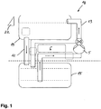
- Fig. 1 shows a typical for the prior art device 18 with a display with input unit 22 and an oil-filled tank 19, in which on oil off and supplying lines 12, 13 and a pump 5 is formed a circuit, the oil from the basin 19, circulated through a filter 15 and back into the basin 19.
- sensors are typically installed at individual or multiple points in the circuit or in the oil basin 19 to monitor the oil.
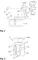
- Fig. 2 illustrates how an inventive oil meter 1 used to monitor an existing oil basin 19 can be.
- the probe 2 must be introduced into the oil so that oil can be taken from the basin via an inlet opening 3 at the distal end 20 of the probe 2 and fed to a measuring chamber 4 of the oil meter connected to the probe by means of a pump 5 integrated in the oil meter ,
- a pump 5 integrated in the oil meter
- This can be done in the simplest case by an integrated into the probe or trained by them Zu-12 and return line 13 in the form of a tube 14.
- double-executed hose or pipe lines 14, preferably as separate supply / return lines 12, 13, may be formed in or through the probe.
- the pump can be operated in such a way that it conveys oil examined in the measuring chamber 4 back to the oil basin 19 via a hose or pipeline 14.
- the oil meter may further comprise an electronic unit 6 and a proximal temperature sensor 9, which are preferably housed in a housing 17 arranged at the proximal end 21 of the probe 2.
- the electronics unit can preferably be set up to control the pump and / or to determine the oil quality.
- This temperature sensor can be designed in particular as a thermocouple. Due to the design of the oil meter with a compact and lightweight housing 17 and a independently movable probe 2, it is in particular, as in Fig. 2 indicated, possible to change a position of the probe 2 relative to the position of the housing 17, and also, the oil meter 1 in total in the position variable, in particular removable, to attach to the oil basin 19. As a result, the handling of the oil meter 1 is substantially improved.
- Fig. 3 shows a schematic view of a housing 17 of an inventive oil meter 1:
- the oil meter may comprise a measuring cell 4, a pump 5, an interface 1, and an electronic unit 6, wherein the electronic unit 6 via control - And supply lines 23 may be connected to the other components as shown.
- the electronic unit for reading and / or controlling the measuring cell 4, and / or for reading and / or controlling of distal and / or proximal temperature sensors 6,7 and / or an interface, such as a wireless RF interface, and / or be set up to record a measured oil quality.
- the oil meter 1 may also have means for electrical measurement, in particular capacitive measurement, the permittivity of located in the measuring chamber 4 oil.
- an additional proximal temperature sensor 9 is provided, which, as in Fig.2 can be seen, in particular in the immediate vicinity of the measuring chamber and / or detected in the measuring chamber 4, a temperature.
- a very compact design of the housing 17 in total can be achieved if the pump 5 is designed as a peristaltic pump.
- Further improvements of the oil meter 1 result if, as in Figure 3 1, the electronic unit 6 has a data memory 10 for storing acquired measured values and / or an interface 11, preferably a wireless interface 11.
- the oil meter 1 can also in the area of the measuring chamber 4 a in Fig. 3 not shown apparatus for detecting and / or displaying the level of the oil in the measuring chamber 4, wherein preferably the electronic unit is part of this device.
- This device can thus be present, for example, in the form of a simple viewing window on the measuring chamber that can be filled with oil, as a signal light, or as an indicator in a display 22 of the oil meter 1, for example.
- the oil meter 1 has means for detecting the level of the oil in the measuring chamber 4 by means of a capacitive measurement, wherein concomitantly or alternatively, the electronic unit 6 for starting a, preferably capacitive, measurement of oil quality after detection of a Minimum level of the oil in the measuring chamber 4 may be established.
- this functionality is made possible by the running between the individual components of the housing 17 control and supply lines 23.
- the probe 2 can be reversibly attached to the housing 17 or permanently installed with this. How through Fig. 3 indicated, the pump 5 is preferably arranged between the measuring cell 4 and the probe 2.
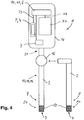
- FIG. 4 shows Fig. 4 in that, with the aid of a changeover valve 16, further probes 2 according to the invention can be connected or arranged on the oil meter 1.
- the probes can each be equipped with distal temperature sensors 7 and filters 15 and have in the form of hose or pipe 14 present supply and return lines 12, 13 or form such lines.
- the filter which filters the oil to be examined before entering the measuring chamber, can also be arranged within the housing 17, but preferably, as in Figure 4 shown at the distal end 20 of the probe 2.
- the housing 17 at the proximal end 21 of the probe. 2
- an electronic unit 6 with data memory 10 and interface 11
- a measuring cell 4 with integrated proximal temperature sensor 9 a pump 5 and a display 22 with input unit.
- an oil measuring device 1 For monitoring an oil located in a basin 19, it is proposed to equip an oil measuring device 1 with a rigid or flexible probe 2, so that oil from the basin 19 can be withdrawn via an inlet opening 3 at the proximal end of the probe 2 with the aid of a pump 5 integrated in the oil measuring device 1 in a connected to the probe measuring chamber 4 of the oil meter 1 is conveyed.
- the oil meter 1 has a measuring means for determining the quality of befindliches in the measuring chamber 4 oil and the pump 5, in conjunction with the probe 2, is arranged so that oil from the measuring chamber 4 to the inlet port 3 and thus to the basin 19 is traceable.
Landscapes
- Food Science & Technology (AREA)
- Engineering & Computer Science (AREA)
- Chemical & Material Sciences (AREA)
- Health & Medical Sciences (AREA)
- Life Sciences & Earth Sciences (AREA)
- Immunology (AREA)
- Pathology (AREA)
- Analytical Chemistry (AREA)
- Biochemistry (AREA)
- General Health & Medical Sciences (AREA)
- General Physics & Mathematics (AREA)
- Physics & Mathematics (AREA)
- Medicinal Chemistry (AREA)
- Chemical Kinetics & Catalysis (AREA)
- Electrochemistry (AREA)
- Investigating Or Analyzing Materials By The Use Of Electric Means (AREA)
- Lubrication Details And Ventilation Of Internal Combustion Engines (AREA)
- Frying-Pans Or Fryers (AREA)
- Measuring Volume Flow (AREA)
Applications Claiming Priority (1)
| Application Number | Priority Date | Filing Date | Title |
|---|---|---|---|
| DE102016007668.2A DE102016007668A1 (de) | 2016-06-24 | 2016-06-24 | Ölmessgerät und Verfahren zur Überwachung eines in einem Becken befindlichen Öls |
Publications (2)
| Publication Number | Publication Date |
|---|---|
| EP3273235A2 true EP3273235A2 (fr) | 2018-01-24 |
| EP3273235A3 EP3273235A3 (fr) | 2018-06-13 |
Family
ID=59312939
Family Applications (1)
| Application Number | Title | Priority Date | Filing Date |
|---|---|---|---|
| EP17001065.6A Withdrawn EP3273235A3 (fr) | 2016-06-24 | 2017-06-23 | Appareil de mesure d'huile et procédé de surveillance d'une huile se trouvant dans une cuve |
Country Status (4)
| Country | Link |
|---|---|
| US (1) | US10725009B2 (fr) |
| EP (1) | EP3273235A3 (fr) |
| CN (1) | CN107543846A (fr) |
| DE (1) | DE102016007668A1 (fr) |
Families Citing this family (6)
| Publication number | Priority date | Publication date | Assignee | Title |
|---|---|---|---|---|
| PL3764858T3 (pl) * | 2018-03-16 | 2024-07-15 | Pitco Frialator, Inc. | Układ detekcji i kontroli poziomu płynu |
| US11209408B2 (en) * | 2019-03-19 | 2021-12-28 | Frontline International, Inc. | Cooking oil pumping station with oil quality sensor |
| US11454571B2 (en) * | 2019-08-21 | 2022-09-27 | Pratt & Whitney Canada Corp. | Sampling tool for lubricating fluid analysis |
| US12150593B2 (en) * | 2020-01-30 | 2024-11-26 | Jae Gon Kim | Frying apparatus having oil recycling and purifying function and frying oil separating function |
| JP7588847B2 (ja) | 2021-07-16 | 2024-11-25 | 株式会社パロマ | フライヤー |
| CN116296565B (zh) * | 2022-12-16 | 2025-11-11 | 中国石油化工股份有限公司 | 一种用于储运油库的液体石油取样器 |
Citations (7)
| Publication number | Priority date | Publication date | Assignee | Title |
|---|---|---|---|---|
| US4942770A (en) * | 1988-09-01 | 1990-07-24 | Seifert Gunilla K E | Automatic aseptic sampling apparatus |
| US5417107A (en) * | 1993-09-21 | 1995-05-23 | Paul-Munroe Engineering | Method and capacitance probe arrangement |
| US5821406A (en) * | 1997-02-27 | 1998-10-13 | Koch Industries, Inc. | Crude oil measurement system and method |
| US20090252842A1 (en) * | 2008-04-04 | 2009-10-08 | 3M Innovative Properties Company | Apparatus, systems, and methods of extending useful life of food treating media by inhibiting degradation thereof |
| US20090309619A1 (en) * | 2007-06-28 | 2009-12-17 | Martin Behle | Oil Quality sensor and adapter for deep fryers |
| US20130036916A1 (en) * | 2010-08-22 | 2013-02-14 | Henny Penny Corporation | Systems and methods for single-sensor oil quality measurement |
| EP2937692A2 (fr) * | 2014-04-04 | 2015-10-28 | WTW Wissenschaftlich-Technische Werkstätten GmbH | Capteur de qualite d'huile et appareil de friture dote d'un tel capteur de qualite d'huile |
Family Cites Families (20)
| Publication number | Priority date | Publication date | Assignee | Title |
|---|---|---|---|---|
| JPH01160511A (ja) * | 1987-11-12 | 1989-06-23 | Food Autom Service Technic Inc | 深い油フライなべ用温度プローブ装置 |
| US5818731A (en) * | 1995-08-29 | 1998-10-06 | Mittal; Gauri S. | Method and apparatus for measuring quality of frying/cooking oil/fat |
| US5706717A (en) * | 1996-11-12 | 1998-01-13 | America's Favorite Chicken Co. | Heating control system for a gas fryer |
| FR2792414B1 (fr) * | 1999-04-13 | 2001-09-21 | Metatron | Procede et dispositif de controle in situ d'une cuve contenant une huile ou graisse de friture |
| EP1046908B1 (fr) * | 1999-04-22 | 2010-05-26 | ebro Electronic GmbH & Co. KG | Dispositif de mesure de la condition d'huiles et de graisses |
| DE10163760C5 (de) * | 2001-12-28 | 2012-02-02 | Ebro Electronic Gmbh & Co. Kg | Vorrichtung und Verfahren zum Messen des Zustandes von Ölen und Fetten |
| AU2003207699A1 (en) * | 2002-01-25 | 2003-09-02 | Hydrolab, L.L.C. | System and method for preventing fouling in sensors |
| US6897661B2 (en) * | 2003-03-14 | 2005-05-24 | Steris Inc. | Method and apparatus for detection of contaminants in a fluid |
| DE102006003733B3 (de) * | 2006-01-26 | 2007-03-29 | Testo Ag | Verfahren zur Prüfung eines Messgerätes |
| US9861234B2 (en) * | 2007-02-15 | 2018-01-09 | Illinois Tool Works, Inc. | Oil reclamation device and process |
| MX2009013590A (es) * | 2007-06-28 | 2010-03-18 | Frymaster Llc | Sensor de calidad de aceite y calentador de aceite para freidoras de inmersion. |
| DE102007036473A1 (de) * | 2007-08-01 | 2009-02-05 | Testo Ag | Vorrichtung zum Messen des Zustands eines Messguts, insbesondere von Ölen oder Fetten |
| US20090084273A1 (en) * | 2007-09-27 | 2009-04-02 | The Frymaster Corporation Llc | Low oil volume fryer with automatic filtration and top-off capability |
| EP2827753B1 (fr) * | 2012-03-21 | 2017-12-27 | Testo SE & Co. KGaA | Dispositif de friture et procédé de commande d'un dispositif de friture |
| JP2014153271A (ja) * | 2013-02-12 | 2014-08-25 | Horiba Advanced Techno Co Ltd | 比抵抗測定装置、液体試料管理方法及び液体試料管理システム |
| EP3161465B1 (fr) * | 2014-06-30 | 2019-07-24 | Pitco Frialator, Inc. | Système et procédé de détection de qualité d'huile |
| CN106574941A (zh) * | 2014-08-01 | 2017-04-19 | 弗瑞马斯特公司 | 用于烹饪油品质传感器的方法和装置 |
| CN204561801U (zh) * | 2015-04-03 | 2015-08-19 | 佛山市顺德区美的电热电器制造有限公司 | 设置有无线测温装置的烹饪器具 |
| US9841394B2 (en) * | 2015-11-16 | 2017-12-12 | Pitco Frialator, Inc. | System and method for sensing oil quality |
| US10436730B2 (en) * | 2015-12-21 | 2019-10-08 | Pitco Frialator, Inc. | System and method for sensing oil quality |
-
2016
- 2016-06-24 DE DE102016007668.2A patent/DE102016007668A1/de not_active Ceased
-
2017
- 2017-06-23 EP EP17001065.6A patent/EP3273235A3/fr not_active Withdrawn
- 2017-06-23 US US15/631,433 patent/US10725009B2/en not_active Expired - Fee Related
- 2017-06-26 CN CN201710490728.0A patent/CN107543846A/zh active Pending
Patent Citations (7)
| Publication number | Priority date | Publication date | Assignee | Title |
|---|---|---|---|---|
| US4942770A (en) * | 1988-09-01 | 1990-07-24 | Seifert Gunilla K E | Automatic aseptic sampling apparatus |
| US5417107A (en) * | 1993-09-21 | 1995-05-23 | Paul-Munroe Engineering | Method and capacitance probe arrangement |
| US5821406A (en) * | 1997-02-27 | 1998-10-13 | Koch Industries, Inc. | Crude oil measurement system and method |
| US20090309619A1 (en) * | 2007-06-28 | 2009-12-17 | Martin Behle | Oil Quality sensor and adapter for deep fryers |
| US20090252842A1 (en) * | 2008-04-04 | 2009-10-08 | 3M Innovative Properties Company | Apparatus, systems, and methods of extending useful life of food treating media by inhibiting degradation thereof |
| US20130036916A1 (en) * | 2010-08-22 | 2013-02-14 | Henny Penny Corporation | Systems and methods for single-sensor oil quality measurement |
| EP2937692A2 (fr) * | 2014-04-04 | 2015-10-28 | WTW Wissenschaftlich-Technische Werkstätten GmbH | Capteur de qualite d'huile et appareil de friture dote d'un tel capteur de qualite d'huile |
Non-Patent Citations (1)
| Title |
|---|
| ANONYMOUS: "FCU 1000 Serie FluidControl Unit, Betriebs- und Wartungsanleitung", HYDAC INTERNATIONAL, 12 April 2007 (2007-04-12), XP055553550 * |
Also Published As
| Publication number | Publication date |
|---|---|
| US10725009B2 (en) | 2020-07-28 |
| CN107543846A (zh) | 2018-01-05 |
| US20170367535A1 (en) | 2017-12-28 |
| EP3273235A3 (fr) | 2018-06-13 |
| DE102016007668A1 (de) | 2017-12-28 |
Similar Documents
| Publication | Publication Date | Title |
|---|---|---|
| EP3273235A2 (fr) | Appareil de mesure d'huile et procédé de surveillance d'une huile se trouvant dans une cuve | |
| EP2937692B1 (fr) | Capteur de qualite d'huile et appareil de friture dote d'un tel capteur de qualite d'huile | |
| EP1046908B1 (fr) | Dispositif de mesure de la condition d'huiles et de graisses | |
| DE60025181T2 (de) | Verfahren und vorrichtung zur steuerung "in situ" einer fritteuse | |
| DE3009549C2 (de) | Einrichtung zur selbsttätigen Anzeige von Mengenänderungen in Flüssigkeitsbehältern | |
| EP2065685B1 (fr) | Capteur de niveau de remplissage pour un aliment liquide dans un récipient | |
| EP3315784B1 (fr) | Groupe de pompage submersible et procédé de fonctionnement d'un groupe de pompage submersible | |
| DE102012008612A1 (de) | Temperaturmessvorrichtung | |
| DE69404169T2 (de) | Verfahren und Einrichtung zur Wasserüberwachung mittels elektrischer Wassertiere | |
| WO2015090854A1 (fr) | Appareil de terrain pour automatismes de processus | |
| DE102017104492A1 (de) | Vorrichtung und Verfahren zur Bereitstellung von Reinigungsfluid | |
| EP1466170A2 (fr) | Systeme de mesure et systeme de detection pour determiner une caracteristique d'un fluide et procede pour faire fonctionner ces systemes | |
| EP2990777B1 (fr) | Dispositif et procédé de détection de propriétés ou d'un niveau de remplissage d'un milieu dans un récipient | |
| DE19627587A1 (de) | Vorrichtung zur Überwachung von Gebrauchseigenschaften von Fluiden, insbesondere von Druckflüssigkeiten in fluidtechnischen Anlagen | |
| DE102016124796A1 (de) | Sensorkopfmodul zur kontinuierlichen automatisierten Datenerfassung | |
| DE102015210337B4 (de) | Kaffeeautomat | |
| DE102014214346B4 (de) | Haushaltsgerät | |
| DE102017128166A1 (de) | Anordnung zur Abfrage eines kritischen Füllstandes oder eines Grenzstandes in einem Tank | |
| DE102012218574B4 (de) | Sensor | |
| DE19834781A1 (de) | Verfahren zur Bestimmung wechselnder Eiskonzentrationen in Binäreisvolumen | |
| EP1582848A1 (fr) | Procédé et dispositif pour tester le type et la qualité d'un milieu liquide dans un réservoir | |
| DE102020109699A1 (de) | Verfahren zur kapazitiven Bestimmung des Füllstandes eines Mediums in einem Behälter mit mehreren durch die Wandung des Behälters vom Medium getrennten Messelektroden | |
| DE102020117844A1 (de) | Reinigungschemiebausystem und Gargerät | |
| DE202014103011U1 (de) | Vorrichtung, System und Messeinrichtung zum Messen eines Füllstands | |
| DE68919841T2 (de) | Testen bakteriologischer aktivität. |
Legal Events
| Date | Code | Title | Description |
|---|---|---|---|
| PUAI | Public reference made under article 153(3) epc to a published international application that has entered the european phase |
Free format text: ORIGINAL CODE: 0009012 |
|
| STAA | Information on the status of an ep patent application or granted ep patent |
Free format text: STATUS: THE APPLICATION HAS BEEN PUBLISHED |
|
| AK | Designated contracting states |
Kind code of ref document: A2 Designated state(s): AL AT BE BG CH CY CZ DE DK EE ES FI FR GB GR HR HU IE IS IT LI LT LU LV MC MK MT NL NO PL PT RO RS SE SI SK SM TR |
|
| AX | Request for extension of the european patent |
Extension state: BA ME |
|
| RIC1 | Information provided on ipc code assigned before grant |
Ipc: G01N 33/03 20060101AFI20180131BHEP |
|
| PUAL | Search report despatched |
Free format text: ORIGINAL CODE: 0009013 |
|
| AK | Designated contracting states |
Kind code of ref document: A3 Designated state(s): AL AT BE BG CH CY CZ DE DK EE ES FI FR GB GR HR HU IE IS IT LI LT LU LV MC MK MT NL NO PL PT RO RS SE SI SK SM TR |
|
| AX | Request for extension of the european patent |
Extension state: BA ME |
|
| RIC1 | Information provided on ipc code assigned before grant |
Ipc: G01N 33/03 20060101AFI20180508BHEP |
|
| STAA | Information on the status of an ep patent application or granted ep patent |
Free format text: STATUS: REQUEST FOR EXAMINATION WAS MADE |
|
| 17P | Request for examination filed |
Effective date: 20181129 |
|
| RBV | Designated contracting states (corrected) |
Designated state(s): AL AT BE BG CH CY CZ DE DK EE ES FI FR GB GR HR HU IE IS IT LI LT LU LV MC MK MT NL NO PL PT RO RS SE SI SK SM TR |
|
| STAA | Information on the status of an ep patent application or granted ep patent |
Free format text: STATUS: EXAMINATION IS IN PROGRESS |
|
| 17Q | First examination report despatched |
Effective date: 20200318 |
|
| STAA | Information on the status of an ep patent application or granted ep patent |
Free format text: STATUS: THE APPLICATION IS DEEMED TO BE WITHDRAWN |
|
| 18D | Application deemed to be withdrawn |
Effective date: 20220412 |