EP3273625B1 - Dispositif de branchement étendu et procédé de commande d'un tel dispositif - Google Patents
Dispositif de branchement étendu et procédé de commande d'un tel dispositif Download PDFInfo
- Publication number
- EP3273625B1 EP3273625B1 EP16764443.4A EP16764443A EP3273625B1 EP 3273625 B1 EP3273625 B1 EP 3273625B1 EP 16764443 A EP16764443 A EP 16764443A EP 3273625 B1 EP3273625 B1 EP 3273625B1
- Authority
- EP
- European Patent Office
- Prior art keywords
- port
- branching
- terminal station
- coupled
- branching unit
- Prior art date
- Legal status (The legal status is an assumption and is not a legal conclusion. Google has not performed a legal analysis and makes no representation as to the accuracy of the status listed.)
- Active
Links
Images



Classifications
-
- G—PHYSICS
- G02—OPTICS
- G02B—OPTICAL ELEMENTS, SYSTEMS OR APPARATUS
- G02B6/00—Light guides; Structural details of arrangements comprising light guides and other optical elements, e.g. couplings
- G02B6/24—Coupling light guides
- G02B6/26—Optical coupling means
- G02B6/28—Optical coupling means having data bus means, i.e. plural waveguides interconnected and providing an inherently bidirectional system by mixing and splitting signals
- G02B6/293—Optical coupling means having data bus means, i.e. plural waveguides interconnected and providing an inherently bidirectional system by mixing and splitting signals with wavelength selective means
- G02B6/29346—Optical coupling means having data bus means, i.e. plural waveguides interconnected and providing an inherently bidirectional system by mixing and splitting signals with wavelength selective means operating by wave or beam interference
- G02B6/29361—Interference filters, e.g. multilayer coatings, thin film filters, dichroic splitters or mirrors based on multilayers, WDM filters
- G02B6/29362—Serial cascade of filters or filtering operations, e.g. for a large number of channels
- G02B6/29365—Serial cascade of filters or filtering operations, e.g. for a large number of channels in a multireflection configuration, i.e. beam following a zigzag path between filters or filtering operations
- G02B6/29367—Zigzag path within a transparent optical block, e.g. filter deposited on an etalon, glass plate, wedge acting as a stable spacer
-
- H—ELECTRICITY
- H04—ELECTRIC COMMUNICATION TECHNIQUE
- H04B—TRANSMISSION
- H04B10/00—Transmission systems employing electromagnetic waves other than radio-waves, e.g. infrared, visible or ultraviolet light, or employing corpuscular radiation, e.g. quantum communication
- H04B10/29—Repeaters
-
- H—ELECTRICITY
- H04—ELECTRIC COMMUNICATION TECHNIQUE
- H04B—TRANSMISSION
- H04B10/00—Transmission systems employing electromagnetic waves other than radio-waves, e.g. infrared, visible or ultraviolet light, or employing corpuscular radiation, e.g. quantum communication
- H04B10/60—Receivers
- H04B10/61—Coherent receivers
- H04B10/614—Coherent receivers comprising one or more polarization beam splitters, e.g. polarization multiplexed [PolMux] X-PSK coherent receivers, polarization diversity heterodyne coherent receivers
-
- H—ELECTRICITY
- H04—ELECTRIC COMMUNICATION TECHNIQUE
- H04J—MULTIPLEX COMMUNICATION
- H04J14/00—Optical multiplex systems
- H04J14/02—Wavelength-division multiplex systems
- H04J14/0201—Add-and-drop multiplexing
- H04J14/0202—Arrangements therefor
- H04J14/0209—Multi-stage arrangements, e.g. by cascading multiplexers or demultiplexers
-
- H—ELECTRICITY
- H04—ELECTRIC COMMUNICATION TECHNIQUE
- H04J—MULTIPLEX COMMUNICATION
- H04J14/00—Optical multiplex systems
- H04J14/02—Wavelength-division multiplex systems
- H04J14/0201—Add-and-drop multiplexing
- H04J14/0202—Arrangements therefor
- H04J14/021—Reconfigurable arrangements, e.g. reconfigurable optical add/drop multiplexers [ROADM] or tunable optical add/drop multiplexers [TOADM]
- H04J14/0212—Reconfigurable arrangements, e.g. reconfigurable optical add/drop multiplexers [ROADM] or tunable optical add/drop multiplexers [TOADM] using optical switches or wavelength selective switches [WSS]
-
- H—ELECTRICITY
- H04—ELECTRIC COMMUNICATION TECHNIQUE
- H04J—MULTIPLEX COMMUNICATION
- H04J14/00—Optical multiplex systems
- H04J14/02—Wavelength-division multiplex systems
- H04J14/0201—Add-and-drop multiplexing
- H04J14/0215—Architecture aspects
- H04J14/0216—Bidirectional architectures
-
- H—ELECTRICITY
- H04—ELECTRIC COMMUNICATION TECHNIQUE
- H04J—MULTIPLEX COMMUNICATION
- H04J14/00—Optical multiplex systems
- H04J14/02—Wavelength-division multiplex systems
- H04J14/0201—Add-and-drop multiplexing
- H04J14/0215—Architecture aspects
- H04J14/0219—Modular or upgradable architectures
-
- H—ELECTRICITY
- H04—ELECTRIC COMMUNICATION TECHNIQUE
- H04J—MULTIPLEX COMMUNICATION
- H04J14/00—Optical multiplex systems
- H04J14/02—Wavelength-division multiplex systems
- H04J14/0201—Add-and-drop multiplexing
- H04J14/0215—Architecture aspects
- H04J14/022—For interconnection of WDM optical networks
Definitions
- the present invention relates to an extended branching device and a control method of an extended branching device, and, more particularly, to an extended branching device and a control method thereof for use in a submarine cable system.
- a branching device installed on the bottom of the sea is used in order to connect a plurality of terminal stations installed on land with each other.
- the branching device connects transmission lines including a plurality of submarine cables with each other according to predetermined specifications such as a wavelength.
- communication devices that are used in a submarine cable system are becoming more highly functional year by year. For this reason, there are cases where engineering work for replacing a branching device to something more highly functional is needed after the system has become operational.
- Japanese Patent Application Laid-Open No. 1999-127111 discloses a light signal branching device for use in a transmission line of a wavelength division multiplexing (WDM) light signal.
- WDM wavelength division multiplexing
- US 5,771,112 of HAMEL et al. describes a reconfigurable device for insertion-extraction of wavelengths.
- the device includes optical add-drop multiplexers each having a band pass filter.
- An optical switch has outputs connected to the multiplexers.
- the device may be useful in optical communications.
- connection arrangement provided in an optical path to facilitate changing optical add/drop multiplexer and other component modules while optical traffic is present on the optical path, with minimal interruption to such traffic.
- the connection arrangement has a plurality of optical ports to each of which an optical component can be coupled, and one or more optical switches which can be controlled to selectively include in the optical path or bypass each optical port.
- Such connection arrangements can be coupled in series and/or in parallel for convenient modular add/drop configurations and for opposite directions of transmission of optical traffic on respective optical paths.
- US 2008/0002978 of MIKI ONAKA et al. describes an optical node apparatus which amplifies a WDM signal light input to an input port, and thereafter branches the amplified WDM signal light by an optical branching coupler to send the branched lights to first and second optical paths, and selects the light propagated through the first optical path by an optical switch to amplify the selected light by a post-amplifier, thereby outputting the amplified light from an output port, when the optical node apparatus is operated as an optical amplification repeating node.
- an OADM section is connected between a set of connecting ports on the second optical path, and the adjustment of OADM section id performed utilizing the WDM signal light branched by the optical branching coupler, and thereafter, the switching of the optical switch is performed to select the light on the second optical path side.
- the branching device For change of the specifications of a branching device or addition of a terminal station, the branching device needs to be brought up from the bottom of the sea. For this reason, there is an issue that a cost of engineering work of the branching device is high. There is also an issue that it is needed to suspend communication services that use a transmission path which passes the branching device during the engineering work period of the branching device.
- a first branching device that connects an optical transmission/reception terminal station I and an optical transmission/reception terminal station II is provided with a separation circuit and an insertion circuit having wavelength characteristics. For this reason, in order to change the function of the first branching device, it is necessary to bring up the first branching device and perform engineering work. Therefore, whole communication which passes the first branching device, including communication between the optical transmission/reception terminal station I and optical transmission/reception terminal station II, needs to be suspended during the engineering work period.
- An extended branching device according to claim 1.
- a recording medium recording a program of an extending branching device according to claim 8.
- An extended branching device and a control method of an extended branching device of the present invention have an effect of facilitating engineering work and reducing influence of the engineering work on communication is small.
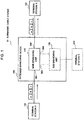
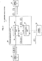
- FIG. 1 and FIG. 2 are block diagrams illustrating exemplary configurations of the submarine cable system 10 of the first example embodiment of the present invention.
- the submarine cable system 10 includes an extended branching device 100, a terminal station A 101, a terminal station B 102 and a terminal station C 103.
- the terminal station A 101, the terminal station B 102 and the terminal station C 103 are optical transmitting and receiving devices which transmit and receive a wavelength division multiplexing light signal (hereinafter, referred to as "WDM signal”), and transmit data such as sound and the like between them via the extended branching device 100.
- WDM signal wavelength division multiplexing light signal
- the extended branching device 100 includes a main branching unit 110 and a sub branching unit 120.
- the main branching unit 110 inputs and outputs a light signal to and from ports 501-504.
- the main branching unit 110 has a function to change inner connections between the ports 501-504.
- the terminal station A 101 is connected to the port 501 of the main branching unit 110 by a submarine optical cable.
- the terminal station B 102 is connected to the port 502 of the main branching unit 110 by a submarine optical cable.
- the main branching unit 110 relays communication between the terminal station A 101 and the terminal station B 102.
- FIG. 1 indicates a case where the sub branching unit 120 and the terminal station C 103 are not in operation.
- the sub branching unit 120 is separated from the main branching unit 110.
- the terminal station A 101 transmits a WDM signal including the respective light signals of wavelengths a, b, and c to the port 501 of the main branching unit 110.
- Wavelengths a, b and c are different wavelengths from each other.
- wavelengths included in a light signal are indicated schematically such as a, b, and c in the neighborhood of an optical path.
- routes inside the main branching unit 110 are set in such a way that all WDM signals transmitted from the terminal station A 101 are transmitted to the terminal station B 102.
- the main branching unit 110 may set inner routes using optical switches.
- FIG. 2 indicates a case where the sub branching unit 120 and the terminal station C 103 are in operation.
- the sub branching unit 120 inputs and outputs a light signal to and from ports 505-507.
- the ports 505 and 506 of the sub branching unit 120 are connected to the ports 503 and 504 of the main branching unit 110, respectively.
- the main branching unit 110 sets inner routes in such a way that light signals of all wavelengths inputted to the port 501 are outputted from the port 503. Further, the main branching unit 110 sets the inner routes in such a way that light signals of all wavelengths inputted to the port 504 are outputted from the port 502.
- the block having the function to set a route inside the main branching unit 110 that have been described in FIG. 1 and FIG. 2 may be called "switch".
- the paths between the port 503 and the port 505 and between the port 504 and the port 506 may be connected to an electric circuit for supervisory control or for feeding power, in addition to the optical transmission path.
- the main branching unit 110 and the sub branching unit 120 may be mounted on different chassis, and the paths between the port 503 and the port 505 and between the port 504 and the port 506 may be connected by submarine cables which can transmit a light signal and supplied power.
- the terminal station C 103 may supply power to the sub branching unit 120 via a submarine cable, and the sub branching unit 120 may supply power to the main branching unit 110.
- the sub branching unit 120 outputs a light signal inputted to the port 505 or 506 from the other port according to specifications set for each wavelength.
- a WDM signal transmitted from the terminal station A 101 is inputted to the port 505 via the port 503 of the main branching unit 110, and light signals are outputted from the port 506 or 507 determined for each wavelength will be described.
- a WDM signal including light signals of wavelengths a, b and c that has been transmitted from the terminal station A 101 is transmitted to the port 505 of the sub branching unit 120 via the ports 501 and 503 of the main branching unit 110.
- the sub branching unit 120 splits the WDM signal received from the main branching unit 110 into signals of respective wavelengths.
- FIG. 2 indicates an example where light signals of wavelength a and wavelength c are destined for the terminal station B 102, and a light signal of wavelength b is destined for the terminal station C 103.
- the sub branching unit 120 receives the WDM signal from the main branching unit 110 at the port 505.
- the sub branching unit 120 outputs the light signal of wavelength a and the light signal of wavelength c that are destined for the terminal station B 102 to the port 504 of the main branching unit 110 from the port 506. Further, to the terminal station C 103, the sub branching unit 120 outputs the light signal of wavelength b that is destined for the terminal station C 103 from the port 507. The light signal of wavelength a and the light signal of wavelength c inputted from the port 506 of the sub branching unit 120 to the port 504 of the main branching unit 110 are outputted from the port 502 of the main branching unit 110 to the terminal station B 102.
- the block having the function by which a light signal is outputted from a port determined for each wavelength in the sub branching unit 120 that have been described in FIG. 1 and FIG. 2 may be called "separating unit".
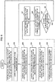
- FIG. 3 is a flow chart illustrating an example of operations of the extended branching device 100 of the present example embodiment.
- the main branching unit 110 sets inner routes in such a way that all WDM signals inputted to the port 501 are outputted from the port 502 (Step S11 of FIG. 3 ).
- Step S11 the sub branching unit 120 is separated from the main branching unit 110, and engineering work for the sub branching unit 120 is conducted (Step S12).
- the main branching unit 110 sets the inner routes in such a way that light signals of all wavelengths inputted to the port 501 are outputted from the port 503 (S13).
- the light signals outputted from the port 503 are outputted to the port 505 of the sub branching unit 120.
- the sub branching unit 120 outputs light signals of the wavelengths destined for the terminal station B 102 to the port 504 of the main branching unit 110 from the port 506 (S14).
- the main branching unit 110 outputs the light signals inputted to the port 504 to the terminal station B 102 from the port 502 (S15).
- the sub branching unit 120 outputs light signals of the wavelength destined for the terminal station C 103 to the terminal station C 103 from the port 507 (S16).
- a WDM signal transmitted from the terminal station A 101 is split by the extended branching device 100 and transmitted to the terminal station B 102 and the terminal station C 103 by predetermined wavelengths.
- Steps S13-S16 do not limit order of processing of a light signal. The processing of a light signal indicated in Steps S13-S16 is performed in parallel.
- Step S11 the main branching unit 110 is controlled in such a way that all light signals inputted to the port 501 of the main branching unit 110 are outputted from the port 502. As a result, a WDM signal which the terminal station A 101 has transmitted passes only the main branching unit 110, and is transmitted to the terminal station B 102.
- Step S17: No the operations of Steps S13-S16 continue.
- the extended branching device 100 of the present example embodiment can add the terminal station C 103 only by engineering work of the sub branching unit 120 without stopping the main branching unit 110. Accordingly, even when the extended branching device 100 is installed in the bottom of the sea, all that is needed is to bring up the sub branching unit 120 at the time of addition work of the terminal station C 103. This enables suppression of engineering work cost.
- the branching function of a WDM signal is included in the sub branching unit 120. For this reason, change of the branching and combining (add/drop) function of a WDM signal for each wavelength in the extended branching device 100, for example, can also be achieved by adjustment or replacement of the sub branching unit 120 only. Furthermore, in the extended branching device 100 of the present example embodiment, communication between the terminal station A 101 and the terminal station B 102 is maintained as illustrated in FIG. 1 even during engineering work of the sub branching unit 120, and, therefore, influence of the engineering work on communication is small.
- the extended branching device 100 of the first example embodiment exerts an effect of facilitating engineering work and reducing influence of the engineering work on communication.
- the extended branching device 100 described in the first example embodiment will be described based on a more detailed structure.
- the identical name and reference sign are attached, and description overlapping that of the first example embodiment will be omitted.
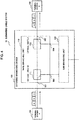
- FIG. 4 is a block diagram illustrating an exemplary configuration of the submarine cable system 10 of the second example embodiment.
- the extended branching device 100 includes the main branching unit 110 and the sub branching unit 120. In this regard, however, FIG. 4 indicates a case where the sub branching unit 120 and the terminal station C 103 are not in operation.
- the main branching unit 110 illustrated in a FIG. 4 includes optical switches 111 and 112. Both the optical switches 111 and 112 are 1x2 optical switches each having one common port and two branching ports, and switch a connection destination of the ports 501 and 502 in the extended branching device 100.
- the common port of the optical switch 111 is connected to the terminal station A 101 via the port 501.
- the common port of the optical switch 112 is connected to the terminal station B 102 via the port 502.
- One of the branching ports of the optical switch 111 is connected to one of the branching ports of the optical switch 112.
- the other of the branching ports of the optical switch 111 is connected to the port 503.
- the other of the branching ports of the optical switch 112 is connected to the port 504.
- FIG. 5 is also a block diagram illustrating an exemplary configuration of the submarine cable system 10 of the second example embodiment.
- FIG. 5 indicates a case where the sub branching unit 120 and the terminal station C 103 are in operation.
- the port 503 of the main branching unit 110 and the port 505 of the sub branching unit 120 are connected, and the port 504 of the main branching unit 110 and the port 506 of the sub branching unit 120 are connected.
- the sub branching unit 120 includes optical couplers 121 and 122, an optical filter A 123 and an optical filter B 124.
- optical couplers 121 and 122 optical directional couplers may be used.
- the optical couplers 121 and 122 split light signals inputted from the port 505 and the port 506 at a predetermined branching ratio (1:1, for example), respectively.
- One of the light signals split by each of the optical couplers is inputted to the optical filter A 123, and the other is inputted to the optical filter B 124.
- dielectric multilayer films may be used as the optical filter A 123 and the optical filter B 124.
- the ports 507 and 508 are connected to the terminal station C 103.
- the terminal station C 103 receives a light signal outputted from the port 507 of the sub branching unit 120.
- a light signal which the terminal station C 103 transmits is inputted to the sub branching unit 120 from the port 508.
- a WDM signal which the terminal station A 101 transmits is split and transmitted to the terminal station B 102 and the terminal station C 103 in the extended branching device 100. Specifically, a WDM signal which the terminal station A 101 transmits is inputted to the sub branching unit 120 via the ports 501, 503 and 505.
- the optical filter A 123 passes a light signal of wavelength a and a light signal of wavelength c and stops a light signal of wavelength b.
- Wavelength a and wavelength c are the wavelengths of light signals to be transmitted from the terminal station A 101 to the terminal station B 102.
- the optical filter B 124 passes a light signal of wavelength b which is included in the other of the light signals split by the optical coupler 121, and outputs it from the port 507.
- Wavelength b is the wavelength of light signals transmitted from the terminal station A 101 to the terminal station C 103.
- the optical filter B 124 stops a light signal of wavelength a and a light signal of wavelength c.
- the optical filter B 124 also passes a light signal of wavelength f of the same wavelength band as wavelength b transmitted from the terminal station C 103 to the terminal station B 102.
- a light signal of wavelength f is inputted from the port 508 to the optical filter B 124 and is outputted to the optical coupler 122.
- the light signal of wavelength a and the light signal of wavelength c which have passed the optical filter A 123 are combined with the light signal of wavelength f which the terminal station C 103 has transmitted.
- the light signal of combined wavelengths a, f and c is outputted to the terminal station B 102 via the ports 506, 504 and 502.
- the extended branching device 100 having the structure illustrated in FIG. 5 may input a WDM signal transmitted by the terminal station B 102 to the sub branching unit 120 via the ports 502, 504 and 506.
- the sub branching unit 120 can make the WDM signal inputted from the terminal station B 102 split to the terminal station A 101 and the terminal station C 103 based on the specifications of the optical filter A 123 and the optical filter B 124.
- the optical filter A 123 may alternatively pass light of one or more wavelength bands including wavelength a or wavelength c.
- the optical filter B 124 may alternatively pass light of a wavelength band including wavelength b and wavelength f. In this case, the wavelengths of the wavelength band including wavelength a, the wavelength band including wavelength b and the wavelength band including wavelength c do not overlap each other.
- the terminal station A 101, the terminal station B 102, and the terminal station C 103 are being connected and operated.
- engineering work such as replacement of the sub branching unit 120 or the like is needed in this state
- operations of the system is as follows.
- the optical switches 111 and 112 are controlled in such a way that the port 501 and the port 502 are connected inside the main branching unit 110.
- the port 501 and the port 502 may be connected to each other inside the main branching unit 110 before separation of the main branching unit 110 and the sub branching unit 120.
- the ports 503 and 504 of the main branching unit 110 and the ports 505 and 506 of the sub branching unit 120 are connected as illustrated in FIG. 5 .
- the optical switch 111 is controlled, after the connection of the main branching unit 110 and the sub branching unit 120, in such a way that the port 501 and the port 503 are connected, and the optical switch 112 is controlled in such a way that the port 502 and the port 504 are connected. That is, the route between the terminal station A 101 and the terminal station B 102 is switched in such a way that the route goes through the sub branching unit 120.
- the optical switches 111 and 112 provided in the main branching unit 110 may be switched in a way being triggered by absence of a light signal from the sub branching unit 120 or absence of the power feeding from the sub branching unit 120.
- the optical switches 111 and 112 may have a monitoring circuit for detecting presence or absence of a light signal or presence or absence of power feeding in the port 504.
- the monitoring circuit switches the optical switches 111 and 112 to the side of the port 503 and the port 504 (that is, the side of the sub branching unit 120).
- the monitoring circuit switches the optical switches 111 and 112 in such a way that the port 501 and the port 502 are connected directly as illustrated in FIG. 4 .
- the optical switches 111 and 112 may have a mechanism to connect the port 501 and the port 502 directly in a case where the main branching unit 110 is not receiving power feeding or when a control signal does not exist.
- the terminal station A 101 and the terminal station B 102 are connected automatically in such a way that only the main branching unit 110 is interposed therebetween.
- the main branching unit 110 does not need power supply for the optical switches 111 and 112. Then, when the main branching unit 110 and the sub branching unit 120 are connected after the end of engineering work, the terminal station A 101 and the terminal station B 102 are connected via the sub branching unit 120 again.
- FIG. 6 is a flow chart illustrating an example of operations of the extended branching device 100 of the present example embodiment.
- the optical switches 111 and 112 are controlled in such a way that light signals of all wavelengths inputted from the terminal station A 101 via the port 501 are outputted to the terminal station B 102 via the port 502 (Step S21 of FIG. 6 ).
- the sub branching unit 120 is separated from the main branching unit 110 in the state that Step S21 has been carried out, and engineering work of the sub branching unit 120 is carried out (S22).
- the main branching unit 110 controls the optical switch 111 in such a way that light signals of all wavelengths inputted from the port 501 are outputted from the port 503 (S23).
- the main branching unit 110 controls the optical switch 112 in such a way that light signals of all wavelengths inputted from the port 504 may be outputted from the port 502 (S24).
- the sub branching unit 120 splits a light signal received from the main branching unit 110 by the optical coupler 121 and inputs split light signals to the optical filter A 123 and the optical filter B 124 (S25).
- the optical filter A 123 passes light signals of the wavelength destined for the terminal station B 102.
- the sub branching unit 120 outputs the light signals destined for the terminal station B 102 from the port 506 to the port 504 of the main branching unit 110 (S26).
- the main branching unit 110 outputs the light signals, which have been inputted from the sub branching unit 120 to the port 504, to the terminal station B 102 from the port 502 (S27).
- the optical filter B 124 passes light signals of the wavelength destined for the terminal station C 103.
- the sub branching unit 120 outputs the light signal destined for the terminal station C 103 from the port 507 to the terminal station C 103 (S28).
- Step S29: Yes When there is a plan of engineering work of the sub branching unit 120 (S29: Yes), the flow returns to Step S21, and the optical switches 111 and 112 are controlled in such a way that a WDM signal transmitted from the terminal station A 101 is transmitted to the terminal station B 102 only via the main branching unit 110.
- Step S23-S28 When engineering work is not resumed, that is, when the usual operation is in progress, the operations of Steps S23-S28 continue (S29: No).
- Steps S23-S28 do not limit order of the processing of light signals.
- the processing of a WDM signal received from the terminal station A 101 in the extended branching device 100 indicated by Steps S23-S28 is performed in parallel.
- An extended branching device on which the branching function between terminal stations is fixed may be called a fixed optical add drop multiplexer (Fixed OADM).
- An OADM whose branching function can be changed may be called a reconfigurable OADM (ROADM). Then, the branching function of such OADM can be implemented on the sub branching unit 120 of the extended branching device 100.
- an ROADM device having a remote-control function of a communication path and optical filters having higher wavelength resolution have been also developed. According to the present example embodiment, it is also easy to improve functionality of the extended branching device 100 by replacing the sub branching unit 120 in operation with the sub branching unit 120 on which such highly functional device is mounted.
- the extended branching device 100 of the present example embodiment exerts an effect of facilitating engineering work and reducing influence of the engineering work on communication.
- the extended branching device 100 of the present example embodiment controls the optical switches 111 and 112 in such a way that the terminal station B 102 and the terminal station A 101 are connected in the main branching unit 110. As a result, communication between the terminal station A 101 and the terminal station B 102 is also maintained during engineering work relating to the terminal station C 103.
- one sub branching unit 120 is connected to one main branching unit 110.
- the third example embodiment a configuration with which two sub branching unit 120 are connected to one main branching unit 110 will be described.
- FIG. 7 is a block diagram illustrating an exemplary configuration of the submarine cable system 20 of the third example embodiment of the present invention.
- the submarine cable system 20 includes an extended branching device 200 instead of the extended branching device 100 described in the first and second example embodiments.
- the extended branching device 200 includes another sub branching unit 130.
- the sub branching unit 130 has ports 509-512, and is cascade-connected to the sub branching unit 120. That is, the ports 509 and 510 of the sub branching unit 130 are connected to the port 507 and the port 508 of the sub branching unit 120 respectively, and the port 511 and 512 of the sub branching unit 130 are connected to the terminal station C 103. Since the structure of the sub branching unit 120 is similar to that of the second example embodiment except for the specification of the optical filter A 123 and the optical filter B 124, the sub branching unit 120 is described simply in FIG. 7 .
- the sub branching unit 130 has a structure similar to that of the sub branching unit 120 basically. That is, the ports 509-512 of the sub branching unit 130 correspond to the ports 505-508 of the sub branching unit 120, respectively.
- the sub branching unit 130 includes optical couplers 131 and 132, an optical filter A 133 and an optical filter B 134. These correspond to the optical couplers 121 and 122, and the optical filter A 123 and the optical filter B 124 of the sub branching unit 120, respectively.
- the sub branching unit 130 outputs, to the port 510 or the port 511, a WDM signal inputted to the port 509 based on the specifications of the optical filter A 133 and the optical filter B 134. The specifications of each optical filter of the sub branching units 120 and 130 will be described later.
- the sub branching unit 130 combines, by the optical coupler 132, a light signal transmitted by the terminal station C 103 and inputted from the port 512 and a light signal that has passed the optical filter A 133, and outputs the combined signal from the port 510.
- the light signal outputted from the port 510 is outputted to the terminal station B 102 via the ports 508 and 506 of the sub branching unit 120 and the ports 504 and 502 of the main branching unit 110.
- the terminal station A 101 transmits a WDM signal of four wavelengths, wavelengths a, b, c, and d.
- the optical filter A 123 of the sub branching unit 120 passes a light signal of wavelength a and a light signal of wavelength c, and stops a light signal of wavelength b and a light signal of wavelength d.
- the optical filter B 124 of the sub branching unit 120 passes a light signal of wavelength b and a light signal of wavelength d, and stops a light signal of wavelength a and a light signal of wavelength c.
- the light signal of wavelength b and the light signal of wavelength d are outputted from the port 507 of the sub branching unit 120.
- the terminal station C 103 was connected to the port 507 and the port 508 of the sub branching unit 120, and the terminal station C 103 was receiving light signals of wavelength b and light signals of wavelength d.
- the light signal of wavelength b inputted to the port 509 of the sub branching unit 130 is outputted from the port 511 to the terminal station C 103.
- the specification of the extended branching device 200 is changed in such a way that the terminal station of the destination of the light signal of wavelength d is changed to the terminal station B 102 from the terminal station C 103. That is, the extended branching device 200 having such structure can change the specification of the extended branching device 200 without replacing the existing sub branching unit 120.
- the route of the light signal of wavelength a and the light signal of wavelength c which pass the sub branching unit 120 needs to be changed such that only the main branching unit 110 is passed through.
- communication between the terminal station A 101 and the terminal station B 102 also becomes possible even during the engineering work period of the sub branching unit 120, as it has been described in the first and second example embodiments.
- a very-short-time shutdown instantaneous shutdown
- a state of the optical switches 111 and 112 does not change during a period of engineering work for adding the sub branching unit 130. Accordingly, the light signal of wavelength a and the light signal of wavelength c transmitted to the main branching unit 110 via the sub branching unit 120 are not influenced by the engineering work for adding the sub branching unit 130.
- the extended branching device 200 of the third example embodiment exerts, in addition to the same effect as that of the first and second example embodiments, an effect of preventing the occurrence of the instantaneous shutdown associated with switching of the optical switches at the time of addition of the sub branching unit 130.
- the extended branching devices 100 and 200 of each example embodiment may include a CPU and a memory.
- the memory is a semiconductor memory and a magnetic disk device, for example, and records a program of the CPU.
- the CPU is a central processing unit, and, by executing the program which is stored in the memory, the function of the extended branching devices 100 and 200 including optical switches are achieved.
- the CPU and the memory are included inside the main branching unit 110, for example, and each unit of the extended branching devices 100 and 200 is controlled. Note that, an optical switch may be switched by remote control from outside of the extended branching devices 100 and 200.
- the extended branching devices 100 and 200 may have a battery, and the battery may provide power to electric circuits of the extended branching devices 100 and 200 including a CPU and a memory.
- each of the example embodiments a submarine cable system having a branching device installed on the bottom of the sea has been described.
- application of each of the example embodiments is not limited to a submarine cable system.
Landscapes
- Engineering & Computer Science (AREA)
- Computer Networks & Wireless Communication (AREA)
- Signal Processing (AREA)
- Physics & Mathematics (AREA)
- Electromagnetism (AREA)
- General Physics & Mathematics (AREA)
- Optics & Photonics (AREA)
- Optical Communication System (AREA)
Claims (8)
- Dispositif de branchement étendu (200), comprenant :un premier moyen de branchement (110) comprenant un premier port (501) couplé à une première station terminale (101) et adapté pour recevoir un signal de multiplexage par répartition en longueur d'onde, WDM, transmis par la première station terminale (101), un second port (502) couplé à une deuxième station terminale (102), un troisième port (503), un quatrième port (504), et un commutateur (111, 112) pour coupler le premier port (501) à un du deuxième port (502) et du troisième port (503) et coupler le deuxième port (502) au quatrième port (504) ;un deuxième moyen de branchement (120) comprenant un cinquième port (505) couplé au troisième port (503), et adapté pour recevoir le signal WDM transmis par la première station terminale (101), un sixième port (506) couplé au quatrième port (504), un septième port (507) couplé à un troisième moyen de branchement (130), et un premier moyen de séparation (121, 123) pour produire en sortie, à destination du sixième port (506), un signal lumineux d'une première longueur d'onde parmi les longueurs d'onde entrées à partir du cinquième port (505) et produire en sortie, à destination du septième port (507), les autres longueurs d'onde entrées depuis le cinquième port (505) ;dans lequelle deuxième moyen de branchement (120) est configuré pour pouvoir être séparé du premier moyen de branchement (110) et ;le troisième moyen de branchement (130), disposé entre le deuxième moyen de branchement (120) et la troisième station terminale (103), comprenant un neuvième port (509) couplé au septième port (507), un dixième port (510) couplé à un huitième port (508) du deuxième moyen de branchement (120), un onzième port (511) couplé à la troisième station terminale (103), et un second moyen de séparation pour produire en sortie à destination du dixième port (510) un signal lumineux d'une deuxième longueur d'onde parmi les longueurs d'ondes entrées depuis le neuvième port (509) et produire en sortie à destination du onzième port (511) un signal lumineux d'une troisième longueur d'onde parmi les longueurs d'ondes entrées depuis le neuvième port (509) ;dans lequelle troisième moyen de branchement (130) est configuré pour pouvoir être séparé du premier moyen de branchement (110) et du deuxième moyen de branchement (120).
- Dispositif de branchement étendu (200) selon la revendication 1, dans lequel
le commutateur fonctionne dans l'un
d'un premier état dans lequel le premier port et le deuxième sont couplés, et
d'un second état dans lequel le premier port est couplé au troisième port et le deuxième port est couplé au quatrième port. - Dispositif de branchement étendu (200) selon la revendication 2, dans lequel
le commutateur comprend un premier commutateur optique et un second commutateur optique qui sont des commutateurs optiques 1x2 présentant chacun un port commun et deux ports de branchement,
le port commun du premier commutateur optique est couplé au premier port,
le port commun du second commutateur optique est couplé au deuxième port,
un des ports de branchement du premier commutateur optique est couplé à un des ports de branchement du second commutateur optique,
un autre des ports de branchement du premier commutateur optique est couplé au troisième port,
un autre des ports de branchement du second commutateur optique est couplé au quatrième port,
dans le premier état, les premier et second commutateurs optiques sont commandés de telle sorte que le port commun du premier commutateur optique soit couplé au port commun du second commutateur optique, et,
dans le second état, les premier et second commutateurs optiques sont commandés de telle sorte que le port commun du premier commutateur optique soit couplé à l'autre des ports de branchement du premier commutateur optique et le port commun du second commutateur optique soit couplé à l'autre des ports de branchement du second commutateur optique. - Dispositif de branchement étendu (200) selon l'une quelconque des revendications 1 à 3, dans lequel
le premier moyen de séparation (121, 123) comprend un premier coupleur optique (121), un premier filtre optique (123) qui laisse passer uniquement la première longueur d'onde, et un second filtre optique (124) qui laisse passer uniquement les autres longueurs d'onde entées depuis le cinquième port (505),
le premier coupleur optique (121) divise un signal lumineux entré depuis le cinquième port en deux signaux lumineux, produit en sortie un des deux signaux lumineux à destination du premier filtre optique (123) et produit en sortie un autre des deux signaux lumineux à destination du second filtre optique (124),
le premier filtre optique (123) produit en sortie à destination du sixième port le signal lumineux de la première longueur d'onde qui est passé à travers celui-ci, et
le second filtre optique (124) produit en sortie à destination du septième port les autres longueurs d'onde entrées depuis le cinquième port qui sont passées à travers celui-ci. - Dispositif de branchement étendu (200) selon la revendication 4, dans lequel
le huitième port est configuré pour recevoir une entrée d'un signal lumineux produit en sortie par le troisième moyen de branchement (130) ;
et
un second coupleur optique (122) pour combiner un signal lumineux de la première longueur d'onde ayant passé dans le premier filtre optique (123) et un signal lumineux entré depuis le huitième port, et pour produire en sortie un signal lumineux combiné depuis le sixième port. - Système de communication comprenant :une première station terminale (101) ;une deuxième station terminale (102) ;une troisième station terminale (103) ; etun dispositif de branchement étendu (200) selon la revendication 1 dans lequel la première station terminale (101) est couplée au premier port (501),la deuxième station terminale (102) est couplée au deuxième port (502), etla troisième station terminale (103) est couplée au onzième port (511).
- Procédé de commande d'un dispositif de branchement étendu (200), le procédé de commande comprenant :dans un premier moyen de branchement (110),le couplage d'un premier port (501) à un d'un deuxième port (502) et d'un troisième port (503), le premier port (501) étant couplé à une première station terminale (101) et recevant un signal de multiplexage par répartition longueur d'onde, WDM, le deuxième port (502) étant couplé à une deuxième station terminale (102) ; etle couplage du deuxième port (502) à un quatrième port (504) ;dans un deuxième moyen de branchement (120) qui est configuré pour pouvoir être séparé du premier moyen de branchement (110),la production en sortie, à destination d'un sixième port (506), d'un signal lumineux d'une première longueur d'onde parmi des signaux lumineux entrés depuis un cinquième port (505), le cinquième port (505) étant couplé au troisième port (503), le sixième port (506) étant couplé au quatrième port (504) ;la production en sortie, à destination d'un septième port (507), des autres longueurs d'ondes entrées depuis le cinquième port (505) ; etdans un troisième moyen de branchement (130) qui est configuré pour pouvoir être séparé du premier moyen de branchement (110) et du deuxième moyen de branchement (120),la production en sortie, à destination d'un dixième port (510), d'un signal lumineux d'une troisième longueur d'onde parmi les longueurs d'ondes entrées depuis un neuvième port (509), le neuvième port (509) étant couplé au septième port (507), le dixième port (510) étant connecté à un huitième port (508) du deuxième moyen de branchement (120) ; etla production en sortie, à destination d'un onzième port (511), d'un signal lumineux d'une troisième longueur d'onde parmi les signaux lumineux entrés depuis le neuvième port (509), le onzième port (511) étant couplé à une troisième station terminale (103).
- Support d'enregistrement enregistrant un programme d'un dispositif de branchement étendu pour amener un ordinateur d'un dispositif de branchement étendu (200) à exécuter les étapes du procédé selon la revendication 7.
Applications Claiming Priority (2)
| Application Number | Priority Date | Filing Date | Title |
|---|---|---|---|
| JP2015051828 | 2015-03-16 | ||
| PCT/JP2016/001279 WO2016147610A1 (fr) | 2015-03-16 | 2016-03-09 | Dispositif de branchement étendu et procédé de commande d'un tel dispositif |
Publications (3)
| Publication Number | Publication Date |
|---|---|
| EP3273625A1 EP3273625A1 (fr) | 2018-01-24 |
| EP3273625A4 EP3273625A4 (fr) | 2018-03-28 |
| EP3273625B1 true EP3273625B1 (fr) | 2019-10-02 |
Family
ID=56919525
Family Applications (1)
| Application Number | Title | Priority Date | Filing Date |
|---|---|---|---|
| EP16764443.4A Active EP3273625B1 (fr) | 2015-03-16 | 2016-03-09 | Dispositif de branchement étendu et procédé de commande d'un tel dispositif |
Country Status (5)
| Country | Link |
|---|---|
| US (1) | US10243685B2 (fr) |
| EP (1) | EP3273625B1 (fr) |
| JP (1) | JP6451831B2 (fr) |
| CN (1) | CN107431536B (fr) |
| WO (1) | WO2016147610A1 (fr) |
Families Citing this family (9)
| Publication number | Priority date | Publication date | Assignee | Title |
|---|---|---|---|---|
| US10715270B2 (en) * | 2016-10-25 | 2020-07-14 | Nec Corporation | Optical branching/coupling device and optical branching/coupling method |
| JP6965937B2 (ja) * | 2017-09-28 | 2021-11-10 | 日本電気株式会社 | 海底分岐装置、光海底ケーブルシステム、光通信方法 |
| WO2019087520A1 (fr) * | 2017-10-30 | 2019-05-09 | 日本電気株式会社 | Système de communication optique sous-marin, et dispositif de raccordement sous-marin |
| GB201803543D0 (en) * | 2018-03-06 | 2018-04-18 | Neptune Subsea Ip Ltd | Submarine optical system |
| JP7024858B2 (ja) * | 2018-03-26 | 2022-02-24 | 日本電気株式会社 | 海底分岐装置、光海底ケーブルシステム及び光通信方法 |
| CN112385148B (zh) * | 2018-07-24 | 2022-06-03 | 日本电气株式会社 | 通信系统、用于通信系统的监测设备和监测方法 |
| EP3852285A4 (fr) * | 2018-09-10 | 2021-11-17 | NEC Corporation | Appareil de commutation de chemin et procédé de commutation de chemin |
| JP7283543B2 (ja) * | 2019-06-24 | 2023-05-30 | 日本電気株式会社 | 分岐装置、海底ケーブルシステム及び分岐装置の制御方法 |
| EP4207632A4 (fr) * | 2020-08-25 | 2024-03-13 | NEC Corporation | Système de câbles optiques sous-marins |
Family Cites Families (15)
| Publication number | Priority date | Publication date | Assignee | Title |
|---|---|---|---|---|
| FR2735931B1 (fr) | 1995-06-21 | 1997-07-25 | Hamel Andre | Dispositif reconfigurable pour insertion-extraction de longueurs d'onde |
| JP3555824B2 (ja) * | 1996-11-21 | 2004-08-18 | 日本電気株式会社 | 分岐装置 |
| JPH11127111A (ja) | 1997-10-20 | 1999-05-11 | Fujitsu Ltd | 光信号分岐装置及び、これを用いた光信号伝送システム |
| US6466341B1 (en) * | 1998-08-03 | 2002-10-15 | Agere Systems Guardian Corp. | Add/drop filter for a multi-wavelength lightwave system |
| US6674935B2 (en) * | 2001-06-15 | 2004-01-06 | Tropic Networks Inc. | Optical connection arrangements |
| US6907159B1 (en) | 2002-02-21 | 2005-06-14 | Broadband Royalty Corporation | Configurable optical add/drop multiplexer with enhanced add channel capacity |
| US20040208509A1 (en) | 2002-03-27 | 2004-10-21 | Gerstel Ornan A. | Upgradeable photonic networking apparatus and method |
| DE10343615A1 (de) * | 2003-09-20 | 2005-04-14 | Marconi Communications Gmbh | Netzknoten für ein optisches Nachrichtenübertragungsnetz |
| JP4528147B2 (ja) * | 2005-02-01 | 2010-08-18 | 株式会社日立製作所 | 光波長挿入分岐装置およびそれを用いた光ネットワーク装置 |
| US20070003283A1 (en) * | 2005-06-29 | 2007-01-04 | At&T Corp. | Dynamic allocation of bandwidth in a bidirectional optical transmission system |
| JP4678647B2 (ja) * | 2005-08-31 | 2011-04-27 | 富士通株式会社 | 光ノードのアップグレード方法および光ノード装置 |
| JP5525041B2 (ja) | 2009-05-14 | 2014-06-18 | タイコ エレクトロニクス サブシー コミュニケーションズ エルエルシー | 別個の分岐ユニットと所定波長フィルタ・ユニットを含む分岐構成およびこれを含むシステムおよび方法 |
| JP2011077808A (ja) * | 2009-09-30 | 2011-04-14 | Fujitsu Ltd | 光伝送システム |
| US9166726B2 (en) * | 2011-04-20 | 2015-10-20 | Nec Corporation | Diverging device with OADM function and wavelength division multiplexing optical network system and method therefor |
| JP6225922B2 (ja) * | 2013-01-23 | 2017-11-08 | 日本電気株式会社 | 光分岐挿入装置、光分岐挿入方法、及び光分岐挿入プログラム |
-
2016
- 2016-03-09 JP JP2017506070A patent/JP6451831B2/ja active Active
- 2016-03-09 WO PCT/JP2016/001279 patent/WO2016147610A1/fr not_active Ceased
- 2016-03-09 US US15/556,518 patent/US10243685B2/en active Active
- 2016-03-09 EP EP16764443.4A patent/EP3273625B1/fr active Active
- 2016-03-09 CN CN201680016229.1A patent/CN107431536B/zh active Active
Non-Patent Citations (1)
| Title |
|---|
| None * |
Also Published As
| Publication number | Publication date |
|---|---|
| WO2016147610A1 (fr) | 2016-09-22 |
| US20180054271A1 (en) | 2018-02-22 |
| CN107431536B (zh) | 2019-12-10 |
| EP3273625A1 (fr) | 2018-01-24 |
| EP3273625A4 (fr) | 2018-03-28 |
| CN107431536A (zh) | 2017-12-01 |
| JP6451831B2 (ja) | 2019-01-16 |
| US10243685B2 (en) | 2019-03-26 |
| JPWO2016147610A1 (ja) | 2017-12-07 |
Similar Documents
| Publication | Publication Date | Title |
|---|---|---|
| EP3273625B1 (fr) | Dispositif de branchement étendu et procédé de commande d'un tel dispositif | |
| US10530470B2 (en) | Optical add/drop device and optical add/drop method | |
| EP3176968B1 (fr) | Dispositif de communication optique, système de communication optique et procédé de communication optique | |
| US10349153B2 (en) | Optical multiplexing and demultiplexing device, and method of controlling optical multiplexing and demultiplexing device | |
| US11438087B2 (en) | Optical branching/coupling device and optical branching/coupling method | |
| US10484086B2 (en) | Optical branching unit | |
| CN107078812B (zh) | 节点设备和用于控制节点设备的方法 | |
| CN111903074B (zh) | 海底分支设备、光学海底缆线系统和光学通信方法 | |
| EP3934135B1 (fr) | Coupleur de branche optique et procédé de couplage de dérivation optique | |
| EP3989593A1 (fr) | Dispositif de dérivation optique sous-marin, système de câble optique sous-marin, procédé de commutation, support lisible par ordinateur non transitoire | |
| CN110024312B (zh) | 光传输设备和光传输方法 | |
| US12439187B2 (en) | Optical branching/coupling device and method for controlling same | |
| WO2013005412A1 (fr) | Dispositif de répartition, système oadm et procédé de répartition |
Legal Events
| Date | Code | Title | Description |
|---|---|---|---|
| STAA | Information on the status of an ep patent application or granted ep patent |
Free format text: STATUS: THE INTERNATIONAL PUBLICATION HAS BEEN MADE |
|
| PUAI | Public reference made under article 153(3) epc to a published international application that has entered the european phase |
Free format text: ORIGINAL CODE: 0009012 |
|
| STAA | Information on the status of an ep patent application or granted ep patent |
Free format text: STATUS: REQUEST FOR EXAMINATION WAS MADE |
|
| 17P | Request for examination filed |
Effective date: 20170905 |
|
| AK | Designated contracting states |
Kind code of ref document: A1 Designated state(s): AL AT BE BG CH CY CZ DE DK EE ES FI FR GB GR HR HU IE IS IT LI LT LU LV MC MK MT NL NO PL PT RO RS SE SI SK SM TR |
|
| AX | Request for extension of the european patent |
Extension state: BA ME |
|
| A4 | Supplementary search report drawn up and despatched |
Effective date: 20180226 |
|
| RIC1 | Information provided on ipc code assigned before grant |
Ipc: H04B 10/29 20130101AFI20180220BHEP Ipc: H04J 14/02 20060101ALI20180220BHEP Ipc: H04J 14/00 20060101ALI20180220BHEP |
|
| DAV | Request for validation of the european patent (deleted) | ||
| DAX | Request for extension of the european patent (deleted) | ||
| GRAP | Despatch of communication of intention to grant a patent |
Free format text: ORIGINAL CODE: EPIDOSNIGR1 |
|
| STAA | Information on the status of an ep patent application or granted ep patent |
Free format text: STATUS: GRANT OF PATENT IS INTENDED |
|
| INTG | Intention to grant announced |
Effective date: 20190115 |
|
| GRAJ | Information related to disapproval of communication of intention to grant by the applicant or resumption of examination proceedings by the epo deleted |
Free format text: ORIGINAL CODE: EPIDOSDIGR1 |
|
| STAA | Information on the status of an ep patent application or granted ep patent |
Free format text: STATUS: REQUEST FOR EXAMINATION WAS MADE |
|
| GRAP | Despatch of communication of intention to grant a patent |
Free format text: ORIGINAL CODE: EPIDOSNIGR1 |
|
| STAA | Information on the status of an ep patent application or granted ep patent |
Free format text: STATUS: GRANT OF PATENT IS INTENDED |
|
| INTC | Intention to grant announced (deleted) | ||
| INTG | Intention to grant announced |
Effective date: 20190513 |
|
| GRAS | Grant fee paid |
Free format text: ORIGINAL CODE: EPIDOSNIGR3 |
|
| GRAA | (expected) grant |
Free format text: ORIGINAL CODE: 0009210 |
|
| STAA | Information on the status of an ep patent application or granted ep patent |
Free format text: STATUS: THE PATENT HAS BEEN GRANTED |
|
| AK | Designated contracting states |
Kind code of ref document: B1 Designated state(s): AL AT BE BG CH CY CZ DE DK EE ES FI FR GB GR HR HU IE IS IT LI LT LU LV MC MK MT NL NO PL PT RO RS SE SI SK SM TR |
|
| REG | Reference to a national code |
Ref country code: GB Ref legal event code: FG4D |
|
| REG | Reference to a national code |
Ref country code: CH Ref legal event code: EP Ref country code: AT Ref legal event code: REF Ref document number: 1187364 Country of ref document: AT Kind code of ref document: T Effective date: 20191015 |
|
| REG | Reference to a national code |
Ref country code: DE Ref legal event code: R096 Ref document number: 602016021765 Country of ref document: DE |
|
| REG | Reference to a national code |
Ref country code: IE Ref legal event code: FG4D |
|
| REG | Reference to a national code |
Ref country code: NL Ref legal event code: MP Effective date: 20191002 |
|
| REG | Reference to a national code |
Ref country code: LT Ref legal event code: MG4D |
|
| REG | Reference to a national code |
Ref country code: AT Ref legal event code: MK05 Ref document number: 1187364 Country of ref document: AT Kind code of ref document: T Effective date: 20191002 |
|
| PG25 | Lapsed in a contracting state [announced via postgrant information from national office to epo] |
Ref country code: PL Free format text: LAPSE BECAUSE OF FAILURE TO SUBMIT A TRANSLATION OF THE DESCRIPTION OR TO PAY THE FEE WITHIN THE PRESCRIBED TIME-LIMIT Effective date: 20191002 Ref country code: LT Free format text: LAPSE BECAUSE OF FAILURE TO SUBMIT A TRANSLATION OF THE DESCRIPTION OR TO PAY THE FEE WITHIN THE PRESCRIBED TIME-LIMIT Effective date: 20191002 Ref country code: GR Free format text: LAPSE BECAUSE OF FAILURE TO SUBMIT A TRANSLATION OF THE DESCRIPTION OR TO PAY THE FEE WITHIN THE PRESCRIBED TIME-LIMIT Effective date: 20200103 Ref country code: NO Free format text: LAPSE BECAUSE OF FAILURE TO SUBMIT A TRANSLATION OF THE DESCRIPTION OR TO PAY THE FEE WITHIN THE PRESCRIBED TIME-LIMIT Effective date: 20200102 Ref country code: AT Free format text: LAPSE BECAUSE OF FAILURE TO SUBMIT A TRANSLATION OF THE DESCRIPTION OR TO PAY THE FEE WITHIN THE PRESCRIBED TIME-LIMIT Effective date: 20191002 Ref country code: PT Free format text: LAPSE BECAUSE OF FAILURE TO SUBMIT A TRANSLATION OF THE DESCRIPTION OR TO PAY THE FEE WITHIN THE PRESCRIBED TIME-LIMIT Effective date: 20200203 Ref country code: SE Free format text: LAPSE BECAUSE OF FAILURE TO SUBMIT A TRANSLATION OF THE DESCRIPTION OR TO PAY THE FEE WITHIN THE PRESCRIBED TIME-LIMIT Effective date: 20191002 Ref country code: LV Free format text: LAPSE BECAUSE OF FAILURE TO SUBMIT A TRANSLATION OF THE DESCRIPTION OR TO PAY THE FEE WITHIN THE PRESCRIBED TIME-LIMIT Effective date: 20191002 Ref country code: FI Free format text: LAPSE BECAUSE OF FAILURE TO SUBMIT A TRANSLATION OF THE DESCRIPTION OR TO PAY THE FEE WITHIN THE PRESCRIBED TIME-LIMIT Effective date: 20191002 Ref country code: BG Free format text: LAPSE BECAUSE OF FAILURE TO SUBMIT A TRANSLATION OF THE DESCRIPTION OR TO PAY THE FEE WITHIN THE PRESCRIBED TIME-LIMIT Effective date: 20200102 Ref country code: ES Free format text: LAPSE BECAUSE OF FAILURE TO SUBMIT A TRANSLATION OF THE DESCRIPTION OR TO PAY THE FEE WITHIN THE PRESCRIBED TIME-LIMIT Effective date: 20191002 Ref country code: NL Free format text: LAPSE BECAUSE OF FAILURE TO SUBMIT A TRANSLATION OF THE DESCRIPTION OR TO PAY THE FEE WITHIN THE PRESCRIBED TIME-LIMIT Effective date: 20191002 |
|
| PG25 | Lapsed in a contracting state [announced via postgrant information from national office to epo] |
Ref country code: IS Free format text: LAPSE BECAUSE OF FAILURE TO SUBMIT A TRANSLATION OF THE DESCRIPTION OR TO PAY THE FEE WITHIN THE PRESCRIBED TIME-LIMIT Effective date: 20200224 Ref country code: CZ Free format text: LAPSE BECAUSE OF FAILURE TO SUBMIT A TRANSLATION OF THE DESCRIPTION OR TO PAY THE FEE WITHIN THE PRESCRIBED TIME-LIMIT Effective date: 20191002 Ref country code: HR Free format text: LAPSE BECAUSE OF FAILURE TO SUBMIT A TRANSLATION OF THE DESCRIPTION OR TO PAY THE FEE WITHIN THE PRESCRIBED TIME-LIMIT Effective date: 20191002 Ref country code: RS Free format text: LAPSE BECAUSE OF FAILURE TO SUBMIT A TRANSLATION OF THE DESCRIPTION OR TO PAY THE FEE WITHIN THE PRESCRIBED TIME-LIMIT Effective date: 20191002 |
|
| PG25 | Lapsed in a contracting state [announced via postgrant information from national office to epo] |
Ref country code: AL Free format text: LAPSE BECAUSE OF FAILURE TO SUBMIT A TRANSLATION OF THE DESCRIPTION OR TO PAY THE FEE WITHIN THE PRESCRIBED TIME-LIMIT Effective date: 20191002 |
|
| REG | Reference to a national code |
Ref country code: DE Ref legal event code: R097 Ref document number: 602016021765 Country of ref document: DE |
|
| PG2D | Information on lapse in contracting state deleted |
Ref country code: IS |
|
| PG25 | Lapsed in a contracting state [announced via postgrant information from national office to epo] |
Ref country code: RO Free format text: LAPSE BECAUSE OF FAILURE TO SUBMIT A TRANSLATION OF THE DESCRIPTION OR TO PAY THE FEE WITHIN THE PRESCRIBED TIME-LIMIT Effective date: 20191002 Ref country code: EE Free format text: LAPSE BECAUSE OF FAILURE TO SUBMIT A TRANSLATION OF THE DESCRIPTION OR TO PAY THE FEE WITHIN THE PRESCRIBED TIME-LIMIT Effective date: 20191002 Ref country code: DK Free format text: LAPSE BECAUSE OF FAILURE TO SUBMIT A TRANSLATION OF THE DESCRIPTION OR TO PAY THE FEE WITHIN THE PRESCRIBED TIME-LIMIT Effective date: 20191002 Ref country code: IS Free format text: LAPSE BECAUSE OF FAILURE TO SUBMIT A TRANSLATION OF THE DESCRIPTION OR TO PAY THE FEE WITHIN THE PRESCRIBED TIME-LIMIT Effective date: 20200202 |
|
| PLBE | No opposition filed within time limit |
Free format text: ORIGINAL CODE: 0009261 |
|
| STAA | Information on the status of an ep patent application or granted ep patent |
Free format text: STATUS: NO OPPOSITION FILED WITHIN TIME LIMIT |
|
| PG25 | Lapsed in a contracting state [announced via postgrant information from national office to epo] |
Ref country code: IT Free format text: LAPSE BECAUSE OF FAILURE TO SUBMIT A TRANSLATION OF THE DESCRIPTION OR TO PAY THE FEE WITHIN THE PRESCRIBED TIME-LIMIT Effective date: 20191002 Ref country code: SM Free format text: LAPSE BECAUSE OF FAILURE TO SUBMIT A TRANSLATION OF THE DESCRIPTION OR TO PAY THE FEE WITHIN THE PRESCRIBED TIME-LIMIT Effective date: 20191002 Ref country code: SK Free format text: LAPSE BECAUSE OF FAILURE TO SUBMIT A TRANSLATION OF THE DESCRIPTION OR TO PAY THE FEE WITHIN THE PRESCRIBED TIME-LIMIT Effective date: 20191002 |
|
| 26N | No opposition filed |
Effective date: 20200703 |
|
| REG | Reference to a national code |
Ref country code: DE Ref legal event code: R119 Ref document number: 602016021765 Country of ref document: DE |
|
| PG25 | Lapsed in a contracting state [announced via postgrant information from national office to epo] |
Ref country code: MC Free format text: LAPSE BECAUSE OF FAILURE TO SUBMIT A TRANSLATION OF THE DESCRIPTION OR TO PAY THE FEE WITHIN THE PRESCRIBED TIME-LIMIT Effective date: 20191002 |
|
| REG | Reference to a national code |
Ref country code: CH Ref legal event code: PL |
|
| PG25 | Lapsed in a contracting state [announced via postgrant information from national office to epo] |
Ref country code: SI Free format text: LAPSE BECAUSE OF FAILURE TO SUBMIT A TRANSLATION OF THE DESCRIPTION OR TO PAY THE FEE WITHIN THE PRESCRIBED TIME-LIMIT Effective date: 20191002 |
|
| REG | Reference to a national code |
Ref country code: BE Ref legal event code: MM Effective date: 20200331 |
|
| PG25 | Lapsed in a contracting state [announced via postgrant information from national office to epo] |
Ref country code: LU Free format text: LAPSE BECAUSE OF NON-PAYMENT OF DUE FEES Effective date: 20200309 |
|
| PG25 | Lapsed in a contracting state [announced via postgrant information from national office to epo] |
Ref country code: DE Free format text: LAPSE BECAUSE OF NON-PAYMENT OF DUE FEES Effective date: 20201001 Ref country code: CH Free format text: LAPSE BECAUSE OF NON-PAYMENT OF DUE FEES Effective date: 20200331 Ref country code: LI Free format text: LAPSE BECAUSE OF NON-PAYMENT OF DUE FEES Effective date: 20200331 Ref country code: IE Free format text: LAPSE BECAUSE OF NON-PAYMENT OF DUE FEES Effective date: 20200309 |
|
| PG25 | Lapsed in a contracting state [announced via postgrant information from national office to epo] |
Ref country code: BE Free format text: LAPSE BECAUSE OF NON-PAYMENT OF DUE FEES Effective date: 20200331 |
|
| PG25 | Lapsed in a contracting state [announced via postgrant information from national office to epo] |
Ref country code: TR Free format text: LAPSE BECAUSE OF FAILURE TO SUBMIT A TRANSLATION OF THE DESCRIPTION OR TO PAY THE FEE WITHIN THE PRESCRIBED TIME-LIMIT Effective date: 20191002 Ref country code: MT Free format text: LAPSE BECAUSE OF FAILURE TO SUBMIT A TRANSLATION OF THE DESCRIPTION OR TO PAY THE FEE WITHIN THE PRESCRIBED TIME-LIMIT Effective date: 20191002 Ref country code: CY Free format text: LAPSE BECAUSE OF FAILURE TO SUBMIT A TRANSLATION OF THE DESCRIPTION OR TO PAY THE FEE WITHIN THE PRESCRIBED TIME-LIMIT Effective date: 20191002 |
|
| PG25 | Lapsed in a contracting state [announced via postgrant information from national office to epo] |
Ref country code: MK Free format text: LAPSE BECAUSE OF FAILURE TO SUBMIT A TRANSLATION OF THE DESCRIPTION OR TO PAY THE FEE WITHIN THE PRESCRIBED TIME-LIMIT Effective date: 20191002 |
|
| REG | Reference to a national code |
Ref country code: GB Ref legal event code: 732E Free format text: REGISTERED BETWEEN 20240321 AND 20240327 |
|
| REG | Reference to a national code |
Ref country code: GB Ref legal event code: 732E Free format text: REGISTERED BETWEEN 20250109 AND 20250115 |
|
| REG | Reference to a national code |
Ref country code: GB Ref legal event code: 732E Free format text: REGISTERED BETWEEN 20260212 AND 20260218 |
|
| PGFP | Annual fee paid to national office [announced via postgrant information from national office to epo] |
Ref country code: GB Payment date: 20260311 Year of fee payment: 11 |
|
| PGFP | Annual fee paid to national office [announced via postgrant information from national office to epo] |
Ref country code: FR Payment date: 20260323 Year of fee payment: 11 |