EP3274209B1 - Système d'aide a la navigation - Google Patents
Système d'aide a la navigation Download PDFInfo
- Publication number
- EP3274209B1 EP3274209B1 EP16713557.3A EP16713557A EP3274209B1 EP 3274209 B1 EP3274209 B1 EP 3274209B1 EP 16713557 A EP16713557 A EP 16713557A EP 3274209 B1 EP3274209 B1 EP 3274209B1
- Authority
- EP
- European Patent Office
- Prior art keywords
- target
- vehicle
- output device
- lighting
- visual output
- Prior art date
- Legal status (The legal status is an assumption and is not a legal conclusion. Google has not performed a legal analysis and makes no representation as to the accuracy of the status listed.)
- Active
Links
Images

Classifications
-
- G—PHYSICS
- G02—OPTICS
- G02B—OPTICAL ELEMENTS, SYSTEMS OR APPARATUS
- G02B27/00—Optical systems or apparatus not provided for by any of the groups G02B1/00 - G02B26/00, G02B30/00
- G02B27/01—Head-up displays
-
- B—PERFORMING OPERATIONS; TRANSPORTING
- B60—VEHICLES IN GENERAL
- B60K—ARRANGEMENT OR MOUNTING OF PROPULSION UNITS OR OF TRANSMISSIONS IN VEHICLES; ARRANGEMENT OR MOUNTING OF PLURAL DIVERSE PRIME-MOVERS IN VEHICLES; AUXILIARY DRIVES FOR VEHICLES; INSTRUMENTATION OR DASHBOARDS FOR VEHICLES; ARRANGEMENTS IN CONNECTION WITH COOLING, AIR INTAKE, GAS EXHAUST OR FUEL SUPPLY OF PROPULSION UNITS IN VEHICLES
- B60K35/00—Instruments specially adapted for vehicles; Arrangement of instruments in or on vehicles
- B60K35/20—Output arrangements, i.e. from vehicle to user, associated with vehicle functions or specially adapted therefor
- B60K35/21—Output arrangements, i.e. from vehicle to user, associated with vehicle functions or specially adapted therefor using visual output, e.g. blinking lights or matrix displays
- B60K35/23—Head-up displays [HUD]
-
- B—PERFORMING OPERATIONS; TRANSPORTING
- B60—VEHICLES IN GENERAL
- B60K—ARRANGEMENT OR MOUNTING OF PROPULSION UNITS OR OF TRANSMISSIONS IN VEHICLES; ARRANGEMENT OR MOUNTING OF PLURAL DIVERSE PRIME-MOVERS IN VEHICLES; AUXILIARY DRIVES FOR VEHICLES; INSTRUMENTATION OR DASHBOARDS FOR VEHICLES; ARRANGEMENTS IN CONNECTION WITH COOLING, AIR INTAKE, GAS EXHAUST OR FUEL SUPPLY OF PROPULSION UNITS IN VEHICLES
- B60K35/00—Instruments specially adapted for vehicles; Arrangement of instruments in or on vehicles
- B60K35/20—Output arrangements, i.e. from vehicle to user, associated with vehicle functions or specially adapted therefor
- B60K35/21—Output arrangements, i.e. from vehicle to user, associated with vehicle functions or specially adapted therefor using visual output, e.g. blinking lights or matrix displays
- B60K35/22—Display screens
-
- B—PERFORMING OPERATIONS; TRANSPORTING
- B60—VEHICLES IN GENERAL
- B60K—ARRANGEMENT OR MOUNTING OF PROPULSION UNITS OR OF TRANSMISSIONS IN VEHICLES; ARRANGEMENT OR MOUNTING OF PLURAL DIVERSE PRIME-MOVERS IN VEHICLES; AUXILIARY DRIVES FOR VEHICLES; INSTRUMENTATION OR DASHBOARDS FOR VEHICLES; ARRANGEMENTS IN CONNECTION WITH COOLING, AIR INTAKE, GAS EXHAUST OR FUEL SUPPLY OF PROPULSION UNITS IN VEHICLES
- B60K35/00—Instruments specially adapted for vehicles; Arrangement of instruments in or on vehicles
- B60K35/20—Output arrangements, i.e. from vehicle to user, associated with vehicle functions or specially adapted therefor
- B60K35/29—Instruments characterised by the way in which information is handled, e.g. showing information on plural displays or prioritising information according to driving conditions
-
- B—PERFORMING OPERATIONS; TRANSPORTING
- B60—VEHICLES IN GENERAL
- B60K—ARRANGEMENT OR MOUNTING OF PROPULSION UNITS OR OF TRANSMISSIONS IN VEHICLES; ARRANGEMENT OR MOUNTING OF PLURAL DIVERSE PRIME-MOVERS IN VEHICLES; AUXILIARY DRIVES FOR VEHICLES; INSTRUMENTATION OR DASHBOARDS FOR VEHICLES; ARRANGEMENTS IN CONNECTION WITH COOLING, AIR INTAKE, GAS EXHAUST OR FUEL SUPPLY OF PROPULSION UNITS IN VEHICLES
- B60K35/00—Instruments specially adapted for vehicles; Arrangement of instruments in or on vehicles
- B60K35/60—Instruments characterised by their location or relative disposition in or on vehicles
-
- G—PHYSICS
- G01—MEASURING; TESTING
- G01C—MEASURING DISTANCES, LEVELS OR BEARINGS; SURVEYING; NAVIGATION; GYROSCOPIC INSTRUMENTS; PHOTOGRAMMETRY OR VIDEOGRAMMETRY
- G01C21/00—Navigation; Navigational instruments not provided for in groups G01C1/00 - G01C19/00
- G01C21/26—Navigation; Navigational instruments not provided for in groups G01C1/00 - G01C19/00 specially adapted for navigation in a road network
- G01C21/265—Navigation; Navigational instruments not provided for in groups G01C1/00 - G01C19/00 specially adapted for navigation in a road network constructional aspects of navigation devices, e.g. housings, mountings, displays
-
- G—PHYSICS
- G01—MEASURING; TESTING
- G01C—MEASURING DISTANCES, LEVELS OR BEARINGS; SURVEYING; NAVIGATION; GYROSCOPIC INSTRUMENTS; PHOTOGRAMMETRY OR VIDEOGRAMMETRY
- G01C21/00—Navigation; Navigational instruments not provided for in groups G01C1/00 - G01C19/00
- G01C21/26—Navigation; Navigational instruments not provided for in groups G01C1/00 - G01C19/00 specially adapted for navigation in a road network
- G01C21/34—Route searching; Route guidance
- G01C21/36—Input/output arrangements for on-board computers
- G01C21/3626—Details of the output of route guidance instructions
- G01C21/3632—Guidance using simplified or iconic instructions, e.g. using arrows
-
- G—PHYSICS
- G01—MEASURING; TESTING
- G01C—MEASURING DISTANCES, LEVELS OR BEARINGS; SURVEYING; NAVIGATION; GYROSCOPIC INSTRUMENTS; PHOTOGRAMMETRY OR VIDEOGRAMMETRY
- G01C21/00—Navigation; Navigational instruments not provided for in groups G01C1/00 - G01C19/00
- G01C21/26—Navigation; Navigational instruments not provided for in groups G01C1/00 - G01C19/00 specially adapted for navigation in a road network
- G01C21/34—Route searching; Route guidance
- G01C21/36—Input/output arrangements for on-board computers
- G01C21/3626—Details of the output of route guidance instructions
- G01C21/3661—Guidance output on an external device, e.g. car radio
-
- G—PHYSICS
- G08—SIGNALLING
- G08G—TRAFFIC CONTROL SYSTEMS
- G08G1/00—Traffic control systems for road vehicles
-
- B—PERFORMING OPERATIONS; TRANSPORTING
- B60—VEHICLES IN GENERAL
- B60K—ARRANGEMENT OR MOUNTING OF PROPULSION UNITS OR OF TRANSMISSIONS IN VEHICLES; ARRANGEMENT OR MOUNTING OF PLURAL DIVERSE PRIME-MOVERS IN VEHICLES; AUXILIARY DRIVES FOR VEHICLES; INSTRUMENTATION OR DASHBOARDS FOR VEHICLES; ARRANGEMENTS IN CONNECTION WITH COOLING, AIR INTAKE, GAS EXHAUST OR FUEL SUPPLY OF PROPULSION UNITS IN VEHICLES
- B60K2360/00—Indexing scheme associated with groups B60K35/00 or B60K37/00 relating to details of instruments or dashboards
- B60K2360/18—Information management
- B60K2360/186—Displaying information according to relevancy
- B60K2360/1868—Displaying information according to relevancy according to driving situations
-
- B—PERFORMING OPERATIONS; TRANSPORTING
- B60—VEHICLES IN GENERAL
- B60K—ARRANGEMENT OR MOUNTING OF PROPULSION UNITS OR OF TRANSMISSIONS IN VEHICLES; ARRANGEMENT OR MOUNTING OF PLURAL DIVERSE PRIME-MOVERS IN VEHICLES; AUXILIARY DRIVES FOR VEHICLES; INSTRUMENTATION OR DASHBOARDS FOR VEHICLES; ARRANGEMENTS IN CONNECTION WITH COOLING, AIR INTAKE, GAS EXHAUST OR FUEL SUPPLY OF PROPULSION UNITS IN VEHICLES
- B60K2360/00—Indexing scheme associated with groups B60K35/00 or B60K37/00 relating to details of instruments or dashboards
- B60K2360/20—Optical features of instruments
- B60K2360/33—Illumination features
- B60K2360/338—Light strips
-
- B—PERFORMING OPERATIONS; TRANSPORTING
- B60—VEHICLES IN GENERAL
- B60K—ARRANGEMENT OR MOUNTING OF PROPULSION UNITS OR OF TRANSMISSIONS IN VEHICLES; ARRANGEMENT OR MOUNTING OF PLURAL DIVERSE PRIME-MOVERS IN VEHICLES; AUXILIARY DRIVES FOR VEHICLES; INSTRUMENTATION OR DASHBOARDS FOR VEHICLES; ARRANGEMENTS IN CONNECTION WITH COOLING, AIR INTAKE, GAS EXHAUST OR FUEL SUPPLY OF PROPULSION UNITS IN VEHICLES
- B60K2360/00—Indexing scheme associated with groups B60K35/00 or B60K37/00 relating to details of instruments or dashboards
- B60K2360/77—Instrument locations other than the dashboard
- B60K2360/785—Instrument locations other than the dashboard on or in relation to the windshield or windows
-
- B—PERFORMING OPERATIONS; TRANSPORTING
- B60—VEHICLES IN GENERAL
- B60K—ARRANGEMENT OR MOUNTING OF PROPULSION UNITS OR OF TRANSMISSIONS IN VEHICLES; ARRANGEMENT OR MOUNTING OF PLURAL DIVERSE PRIME-MOVERS IN VEHICLES; AUXILIARY DRIVES FOR VEHICLES; INSTRUMENTATION OR DASHBOARDS FOR VEHICLES; ARRANGEMENTS IN CONNECTION WITH COOLING, AIR INTAKE, GAS EXHAUST OR FUEL SUPPLY OF PROPULSION UNITS IN VEHICLES
- B60K2360/00—Indexing scheme associated with groups B60K35/00 or B60K37/00 relating to details of instruments or dashboards
- B60K2360/77—Instrument locations other than the dashboard
- B60K2360/794—Instrument locations other than the dashboard on or in doors
-
- G—PHYSICS
- G02—OPTICS
- G02B—OPTICAL ELEMENTS, SYSTEMS OR APPARATUS
- G02B27/00—Optical systems or apparatus not provided for by any of the groups G02B1/00 - G02B26/00, G02B30/00
- G02B27/01—Head-up displays
- G02B27/0101—Head-up displays characterised by optical features
- G02B2027/014—Head-up displays characterised by optical features comprising information/image processing systems
Definitions
- the invention relates to a navigation aid system for a motor vehicle, and more particularly to a system for assisting navigation when changing direction from a first direction to a second direction.
- the invention applies in particular in addition to navigational aid systems and is intended to minimize the cognitive load required for the acquisition and interpretation of information by the driver and to improve the navigation service by case of momentary loss of GPS signal ("Global Positioning System”) or imprecise indication.
- GPS signal Global Positioning System
- the navigation aid systems generally include at least one terrestrial map, a GPS signal receiver, a navigation computer for continuously providing the driver with various navigation information based on the received GPS signals: arrival time, distance remaining to go, next change of orientation or route, current name and route number, etc. ; and a display device adapted to restore the navigation information to the driver.
- a navigation guidance screen displaying directional pointers in the form of arrows.
- the GPS signals often have insufficient precision, for example 5 to 10 meters, to give a sufficiently clear indication to the driver in the event of a complex change of lane: interchanges with multiple inputs and / or outputs, parallel or separating paths in two, roundabouts with multiple outlets and close to each other, etc.
- GPS signals are not completely real-time. Considering the speed of movement of the vehicle and the processing time by the navigation aid system, there is a time difference between the reception of GPS signals and the display of the position of the vehicle to the driver. Therefore, the position indicated by the navigation aid system is always behind the actual position of the vehicle.
- a navigation aid system based on a continuous calculation and can continue to provide a particularly stable vision of a next direction to take, even in the event of momentary loss of GPS signals or imprecise indication.
- a navigation aid system comprising a visual rendering device configured to permanently aim a point of the horizon, in a compass-like manner and to continuously illuminate a component of lighting corresponding to the direction of this point of the horizon in relation to the driving axis, while ensuring that the acquisition and interpretation of this visual information by the driver remain particularly simple, intuitive and effective.
- a navigation aid system when a direction is changed from a first direction to a second direction, comprising a target angle calculation device comprising at least one terrestrial cartography, a sensor of orientation and a calculator adapted to calculate a target angle between the instantaneous position of the vehicle and a fixed point of the terrestrial map located in the second direction, said system further comprising a visual rendering device, receiving the target angle and comprising a zone substantially linear illumination located within the vehicle in the main or peripheral field of view of the driver, the visual information produced by the illumination zone being adapted to continuously indicate the direction towards said fixed point according to the value of the target angle, the visual rendering device being activated only when a delay is below a threshold, the said delay being corresponding to the time remaining before the change of direction and being calculated by a calculator using odometric information.
- the target angle calculation device can also be implemented in a mobile device, for example a smartphone or a tablet, connected to a vehicle network, Bluetooth or MirrorLink, for example.
- the illumination area of the visual rendering device can be installed in the upper part of the dashboard of the vehicle and in the upper part of the driver's door panel and configured to cover a visual field of at least 90 °.
- the visual field corresponding to the peripheral field of vision in which the driver perceives information may be at least 150 °.
- the illumination area of the visual rendering device may comprise for example a plurality of individual lighting components.
- the visual rendering device can be adapted to control the instantaneous illumination of the single individual lighting component corresponding to the instantaneous direction towards the fixed point.
- the light produced by the lighting zone must simply be perceptible in all driving situations and without disturbing the driver in his driving tasks.
- the lighting components of the visual rendering device may be based on LEDs and an optical diffuser. Such a system makes it possible to properly size and control the luminous flux emitted by the device.
- the illumination area of the visual rendering device may comprise a dial or a half-dial divided by a plurality of boxes representing at least an angle between -90 ° and 90 ° and displayed on a screen preferably the table on board or a head-up display, or in a mobile device connected to a vehicle network, Bluetooth or MirrorLink, for example.
- a light sensor may be installed in the vehicle and configured to modulate the luminous intensity of the illumination area of the visual display device according to the luminous flux received from the outside, for example different day situations. or night, glare, etc.
- a method of assisting navigation during a change of direction from a first direction to a second direction in which a first fixed point is defined on a land map. crossing of the change of direction and a second fixed point at a determined distance from the first point in the second direction, an instantaneous target angle is calculated between the instantaneous position of the vehicle and the second fixed point, and a lighting zone specific to the within the vehicle, corresponding to the instantaneous target angle in the main or peripheral field of view of the driver, and a time period corresponding to the time remaining before the change of direction is defined, in using odometric information and activating the visual rendering device only when said delay is below a threshold.
- this time trigger threshold makes it possible to take into account the speed of the vehicle.
- the device is activated late when the movement of the vehicle is slow, for example in the city. This principle is consistent with taking into account the driver's cognitive load and such a configuration makes the navigation aid system as undisturbed as possible to the driver.
- An end zone may be illuminated and flashed outside the illumination area of the visual display device as long as the absolute value of the instantaneous target angle is greater than the maximum angle of the field of view covered by the lighting zone, and it is possible to illuminate an area of the lighting zone angularly closest to the target angle in other cases, when the visual rendering device is activated.
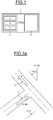
- FIG. 1 schematically illustrates a navigation aid system according to the invention.
- This system 1 is intended to be on board a motor vehicle to provide aids to navigation when the vehicle makes a change of direction, a first direction to a second direction.
- This system 1 comprises a target angle ⁇ calculation device Target 2 comprising at least one terrestrial mapping 3, an orientation sensor 4 and a computer 5 capable of calculating the target angle ⁇ Target between the instantaneous position of the vehicle and a fixed point of terrestrial mapping located in the second direction.
- the navigation aid system 1 further comprises a visual rendering device 6, receiving the target angle ⁇ Target and producing a substantially linear illumination zone located within the vehicle in the principal or peripheral field of view of the driver. .
- This visual information provided by the illumination area is adapted to continuously indicate the direction towards said fixed point as a function of the value of the target angle ⁇ Target .
- the target angle calculation device ⁇ Target can advantageously be implemented in a mobile device, for example a smartphone or a tablet, connected to a network, for example CAN ("Controller Area Network"), of the vehicle by a communication protocol. wired or wireless, the vehicle is equipped, for example Bluetooth or MirrorLink.
- a mobile device for example a smartphone or a tablet
- a network for example CAN ("Controller Area Network")
- the vehicle is equipped, for example Bluetooth or MirrorLink.
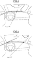
- the first azimuth ⁇ Veh corresponds to the azimuth of the current direction 7 of the vehicle along the driving axis, conventionally referred to north in the direction of clockwise.
- This ⁇ Veh azimuth is updated in real time via the integrated orientation sensor 4 in the vehicle or in the mobile device. This direction is called here the first direction 7.
- the second azimuth ⁇ Next corresponds to the azimuth of the direction, called the second direction 8, after the next change of direction proposed by the navigation aid system according to the terrestrial cartography.
- this azimuth is also referenced with respect to the north in the direction of clockwise.
- the azimuth ⁇ Next indicated in the figure 2a therefore has a negative value.
- the target angle calculation device 2 can advantageously continue to operate in the event of a momentary loss of the GPS signals.
- the figure 2b shows the definition of the target angle ⁇ Target corresponding to the second direction 8, according to the terrestrial map, with respect to the driving axis of the vehicle in the first direction 7.
- this target angle ⁇ Target is not an azimuth and is therefore not located in relation to the north.
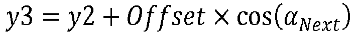
- a first moving point P1 corresponding to the current position of the vehicle is defined on the terrestrial map 3, a first fixed point P2 corresponding to the crossing of the change of direction, a second fixed point P3 of the second direction defined by the fixed azimuth ⁇ Next , located at a determined distance from the first fixed point P2 and a second moving point P4 placed at the abscissa x1 of the first moving point P1 and the ordinate y3 of the second fixed point P3.
- the distance between the first moving point P1 and the first fixed point P2 is defined as D Next .
- the distance determined between the first fixed point P2 and the second fixed point P3 is called Offset here and can have for example a value of two meters or five meters.
- This offset distance is used to define the second fixed point P3, also called "target”, which comprises a point targeted by the visual rendering device according to the invention.
- the two fixed points P2 and P3 are by definition static and provided by the navigation aid system only with each new change of direction.
- ⁇ P3 arccos ⁇ P 1 ⁇ P 4 ⁇ ⁇ ⁇ P 1 ⁇ P 3 ⁇ ⁇ .
- ⁇ Target ⁇ P 3 - ⁇ Veh
- ⁇ Target ⁇ 0 indicates the next direction to the left
- ⁇ Target > 0 indicates the next direction to the right
- the Offset distance is advantageously defined to indicate to the driver that the vehicle is moving in the right direction when the vehicle has passed the crossover P2 of the change of direction.
- the position of the vehicle P1 being the only element dependent on the GPS signals to calculate the target angle ⁇ Target , is correlated with the odometry of the vehicle which provides in particular the speed of the vehicle.
- the target angle calculation device ⁇ Target retains sufficient accuracy and continues to provide the indications of the next change of direction.
- a delay T Next is defined corresponding to the time remaining before the change of direction, calculated by the computer using odometric information, including the speed of the vehicle.
- This delay T Next is used as a control signal of the visual rendering device to determine its activation in order to limit the driving contexts and simplify the acquisition and interpretation of information for the driver.
- the visual rendering device is activated only when said delay is less than a time threshold T Max .
- this time trigger threshold T Max makes it possible to take into account the speed of the vehicle via odometric information available on the CAN network of the vehicle.
- Such a configuration being consistent with taking into account the cognitive load of the driver makes the navigation aid system as undisturbed as possible to the driver.
- the illumination zone 9 of the visual rendering device can be installed in the upper part of the dashboard of the vehicle and in the upper part of the driver's door panel, so that the light produced by the lighting zone 9 is noticeable in the main or peripheral field of view of the driver but without much disturbing the driver on his conduct.
- the illumination zone 9 of the visual rendering device is advantageously configured to cover a sufficiently wide field of view, here 90 °, centered on the driving axis 11. Keeps the peripheral field of vision in which the driver Since information is at least 150 °, the illumination area 9 can extend to cover an even wider field of view.
- the lighting zone 9 of the visual rendering device 6 illustrated on the figure 3 comprises a plurality of individual lighting components, here in number 27.
- the lighting components are indexed from 0 to 26 here, from left to right.
- the lighting components of the visual rendering device 6 are based on LEDs and an optical diffuser.
- each lighting component emits at an angle between -45 ° and 45 °.
- the video output device 6 controls the instantaneous lighting of only the individual light component corresponding to the instantaneous direction ⁇ to Target the second fixed point P3 says "target".
- the visual rendering device 6 When the visual rendering device 6 is activated and the target angle ⁇ Target is outside the field of view covered by the illumination zone, here from -45 ° to 45 °, one illuminates and blinks an end zone outside the lighting zone of the visual rendering device.
- the index lighting component 0 on the left is lit. and flashes.
- the index illumination component 26 on the right is illuminated and flashes.
- the figure 4 shows a situation in which a vehicle is close to a crossing of a change of direction proposed by the navigation aid system 1.
- the visual rendering device 6 illuminates the lighting component corresponding to the target angle ⁇ Target , here 25 °.
- the driver therefore receives an indication of a change of direction at the next crossing on the right.
- the target angle ⁇ Target becomes larger.
- ⁇ Target 45 °, as shown on the figure 5 .
- the driver starts the maneuver and turns right.
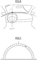
- the figure 6 illustrates a situation in which the change of direction is completed.
- the illuminated lighting component returns to the driving axis 11 to confirm to the driver that the vehicle is moving in the right direction.
- the visual rendering device 6 can be deactivated temporally until the approach of a next change of direction in order to minimize the cognitive load necessary for the acquisition and the reproduction. interpretation of the information by the driver.
- the implementation of the navigation aid system 1 according to the invention remains very simple.
- the target angle calculating device can be integrated directly into the existing vehicle architecture and the visual rendering device requires a moderate retouch at the top of the vehicle dashboard and at the top of the driver's door panel.
- this visual rendering device 6 described has a lighting zone 9 installed in the upper part of the dashboard of the vehicle and in the upper part of the driver's door panel, it is possible to provide a lighting zone.
- 9 comprising a dial or half-dial divided by a plurality of boxes representing at least an angle between -90 ° and 90 °, the target angle ⁇ Target being indicated by a symbol, for example a round disk such as represented in the figure 7 .
- dial or the half-dial on one of the screens available in the vehicle, preferably the dashboard or a head-up display, or in a mobile device, for example a smartphone or a tablet, connected to the CAN network of the vehicle by a wireless communication protocol whose vehicle is equipped, Bluetooth or MirrorLink for example.
- a wireless communication protocol whose vehicle is equipped, Bluetooth or MirrorLink for example.
- a light sensor may be installed in the vehicle and configured to modulate the light intensity of the illumination area 9 of the visual display device 6 according to the light flux received from the outside.
Landscapes
- Engineering & Computer Science (AREA)
- Chemical & Material Sciences (AREA)
- Combustion & Propulsion (AREA)
- Transportation (AREA)
- Mechanical Engineering (AREA)
- Radar, Positioning & Navigation (AREA)
- Remote Sensing (AREA)
- Physics & Mathematics (AREA)
- General Physics & Mathematics (AREA)
- Automation & Control Theory (AREA)
- Optics & Photonics (AREA)
- Navigation (AREA)
- Lighting Device Outwards From Vehicle And Optical Signal (AREA)
- Instrument Panels (AREA)
Description
- L'invention concerne un système d'aide à la navigation pour véhicule automobile, et plus particulièrement un système d'aide à la navigation lors d'un changement de direction d'une première direction vers une deuxième direction.
- L'invention s'applique notamment en complément des systèmes d'aide à la navigation et est destinée à minimiser la charge cognitive nécessaire à l'acquisition et à l'interprétation de l'information par le conducteur et à améliorer la prestation de navigation en cas de perte momentanée du signal GPS (« Global Positioning System ») ou d'indication imprécise.
- Les systèmes d'aide à navigation comprennent généralement au moins une cartographie terrestre, un récepteur des signaux GPS, un calculateur de navigation destiné à fournir en continu au conducteur diverses informations de navigation basées sur les signaux GPS reçus : délai d'arrivée, distance restant à parcourir, prochain changement d'orientation ou de route, nom et numéro de route actuelle, etc. ; et un dispositif d'affichage apte à restituer les informations de navigation au conducteur. On connait par exemple le document
US5964821A qui décrit un écran de guidage de navigation affichant des pointeurs directionnels sous forme de flèches. - Cependant, les signaux GPS possèdent souvent une précision insuffisante, par exemple 5 à 10 mètres, pour donner une indication suffisamment claire au conducteur en cas d'un changement complexe de voie : échangeurs à entrées et/ou sorties multiples, voies parallèles ou se séparant en deux, rond-points à sorties multiples et proches les unes des autre, etc.
- Par ailleurs, les signaux GPS ne sont pas complètement en temps-réel. Compte-tenu de la vitesse de déplacement du véhicule et du temps de traitement par le système d'aide à la navigation, il existe un décalage temporel entre la réception de signaux GPS et l'affichage de la position du véhicule au conducteur. Par conséquent, la position indiquée par le système d'aide à la navigation est toujours en retard par rapport à la position réelle du véhicule.
- En outre, il peut arriver que l'on reçoit des signaux GPS dégradés ou faussés (rebonds des signaux GPS sur une façade en ville), voire que l'on perde temporellement (par exemple dans un tunnel) les signaux GPS. Dans ce dernier cas, la position du véhicule ne peut plus être calculée autrement que par un principe d'extrapolation.
- Dans les situations limites d'embranchement, les imprécisions des systèmes d'aide à la navigation citées ci-dessus peuvent mener à une confusion quant à la voie sur laquelle le véhicule se situe ou celle que le conducteur doit prendre.
- De plus, le dispositif d'affichage du système d'aide à la navigation affiche une cartographie en général simplifiée via un écran intégré dans un véhicule ou dans un dispositif mobile, par exemple un navigateur GPS mobile ou un smartphone avec une application de navigation. En dépit des progrès constatés sur les affichages proposés en 2D ou en 3D, ils présentent cependant toujours certaines limites :
- ils ne peuvent pas compenser efficacement l'imprécision du système d'aide à la navigation,
- ils rentrent en compétition avec la surveillance visuelle et la charge cognitive nécessaire à la gestion d'une situation de conduite complexe, par exemple dans une situation « échangeur » ou « rond-point », et
- la localisation de cet écran dans le véhicule n'est pas toujours optimale pour la prise d'information. En effet, les systèmes d'aide à la navigation sont souvent placés sur la console centrale du véhicule, située entre le conducteur et le passager, qui nécessite un « détournement de regard » du conducteur pour la prise d'information.
- Selon un mode de réalisation, il est proposé un système d'aide à la navigation basé sur un calcul continu et pouvant continuer à fournir une vision particulièrement stable d'une prochaine direction à prendre, même en cas de perte momentanée des signaux GPS ou d'indication imprécise.
- Selon un autre mode de réalisation, il est proposé un système d'aide à la navigation comprenant un dispositif de restitution visuelle configuré pour viser en permanence un point de l'horizon, de manière analogue à une boussole et éclairer en continu un composant d'éclairage correspondant à la direction de ce point de l'horizon par rapport à l'axe de conduite, tout en assurant que l'acquisition et l'interprétation de cette information visuelle par le conducteur restent particulièrement simples, intuitives et efficaces.
- Ainsi, il est proposé un système d'aide à la navigation lors d'un changement de direction d'une première direction vers une deuxième direction, comprenant un dispositif de calcul d'angle cible comportant au moins une cartographie terrestre, un capteur d'orientation et un calculateur apte à calculer un angle cible entre la position instantanée du véhicule et un point fixe de la cartographie terrestre situé dans la deuxième direction, ledit système comprenant en outre un dispositif de restitution visuelle, recevant l'angle cible et comportant une zone d'éclairage sensiblement linéaire située au sein du véhicule dans le champ de vision principal ou périphérique du conducteur, l'information visuelle produite par la zone d'éclairage étant adaptée pour indiquer en continu la direction vers ledit point fixe en fonction de la valeur de l'angle cible, le dispositif de restitution visuelle étant activé uniquement lorsqu'un délai est inférieur à un seuil, ledit délai correspondant au temps restant avant le changement de direction et étant calculé par un calculateur en utilisant des informations odométriques.
- Selon une variante de l'invention, le dispositif de calcul d'angle cible peut être également implémenté dans un dispositif mobile, par exemple un smartphone ou une tablette, relié à un réseau du véhicule, Bluetooth ou MirrorLink par exemple.
- Par ailleurs, la zone d'éclairage du dispositif de restitution visuelle peut être installée en partie supérieure de la planche de bord du véhicule et en partie supérieure du panneau de porte du conducteur et configurée pour couvrir un champ visuel d'au moins 90°. Le champ visuel correspondant au champ de vision périphérique dans lequel le conducteur perçoit des informations peut être d'au moins 150°.
- La zone d'éclairage du dispositif de restitution visuelle peut comporter par exemple une pluralité de composants d'éclairage individuels. Le dispositif de restitution visuelle peut être adapté pour commander l'éclairage instantané du seul composant d'éclairage individuel correspondant à la direction instantanée vers le point fixe.
- La lumière produite par la zone d'éclairage doit simplement être perceptible dans toutes les situations de conduites et sans perturber le conducteur dans ses tâches de conduite.
- En outre, les composants d'éclairage du dispositif de restitution visuelle peuvent être à base de LEDs et d'un diffuseur optique. Un tel système permet de bien dimensionner et de maitriser le flux lumineux émis par le dispositif.
- En variante, la zone d'éclairage du dispositif de restitution visuelle peut comprendre un cadran ou un demi-cadran sectorisé par une pluralité de cases représentant au moins un angle compris entre -90° et 90° et affiché sur un écran de préférence le tableau de bord ou un affichage tête haute, ou dans un dispositif mobile relié à un réseau du véhicule, Bluetooth ou MirrorLink par exemple.
- Dans une implémentation optimale, un capteur de lumière peut être installé dans le véhicule et configuré pour moduler l'intensité lumineuse de la zone d'éclairage du dispositif de restitution visuelle suivant le flux lumineux reçu de l'extérieur, par exemple différentes situations de jour ou de nuit, d'éblouissement, etc.
- Selon un autre aspect de l'invention, il est proposé un procédé d'aide à la navigation lors d'un changement de direction d'une première direction vers une deuxième direction, dans lequel on définit sur une cartographie terrestre un premier point fixe au croisement du changement de direction et un deuxième point fixe à une distance déterminée du premier point dans la deuxième direction, on calcule un angle cible instantané entre la position instantanée du véhicule et le deuxième point fixe, et on éclaire une zone d'éclairage spécifique au sein du véhicule, correspondant à l'angle cible instantané dans le champ de vision principal ou périphérique du conducteur, et on définit un délai correspondant au temps restant avant le changement de direction, en utilisant des informations odométriques et on active le dispositif de restitution visuelle uniquement lorsque ledit délai est inférieur à un seuil.
- L'utilisation de ce seuil de déclenchement temporel permet de prendre compte la vitesse de véhicule. Plus le véhicule se déplace vite, par exemple en déplacement sur voie rapide, plus le dispositif de restitution visuelle est activé tôt. Inversement, le dispositif est activé tard lorsque le déplacement du véhicule est lent, par exemple en ville. Ce principe est cohérent avec une prise en compte de la charge cognitive du conducteur et une telle configuration permet de rendre le système d'aide à la navigation le moins perturbant possible au conducteur.
- On peut éclairer et faire clignoter une zone d'extrémité à l'extérieur de la zone d'éclairage du dispositif de restitution visuelle tant que la valeur absolue de l'angle cible instantané est supérieure à l'angle maximum du champ visuel couvert par la zone d'éclairage, et on peut éclairer une zone de la zone d'éclairage angulairement la plus proche de l'angle cible dans les autres cas, lorsque le dispositif de restitution visuelle est activé.
- D'autres avantages et caractéristiques de l'invention apparaîtront à l'étude de la description détaillée de modes de réalisation, pris à titre d'exemples non limitatifs et illustrés par les dessins annexés sur lesquels :
- La
figure 1 est un schéma bloc du système d'aide à la navigation lors d'un changement de direction d'une première direction vers une deuxième direction selon l'invention ; - Les
figures 2a et2b sont relatives à une définition des paramètres pour le calcul d'angle cible selon l'invention ; - La
figure 3 illustre une intégration type du dispositif de restitution visuelle installé en partie supérieure de la planche de bord du véhicule et en partie supérieure du panneau de porte du conducteur selon l'invention ; - Les
figures 4 à 6 illustrent de manière schématique différentes étapes d'indication du dispositif de restitution visuelle pendant un changement de direction selon l'invention ; et - La
figure 7 illustre un exemple de cadran permettant de représenter l'angle cible sur un écran selon l'invention. - On se réfèrera tout d'abord à la
figure 1 qui illustre schématiquement un système d'aide à la navigation conforme à l'invention. - Ce système 1 est destiné à être embarqué à bord d'un véhicule automobile pour procurer une aide à la navigation lorsque le véhicule opère un changement de direction, d'une première direction à une deuxième direction.
- Ce système 1 comporte un dispositif de calcul d'angle cible αCible 2 comportant au moins une cartographie terrestre 3, un capteur d'orientation 4 et un calculateur 5 apte à calculer l'angle cible αCible entre la position instantanée du véhicule et un point fixe de la cartographie terrestre situé dans la deuxième direction.
- Le système d'aide à la navigation 1 comporte en outre un dispositif de restitution visuelle 6, recevant l'angle cible αCible et produisant une zone d'éclairage sensiblement linéaire située au sein du véhicule dans le champ de vision principal ou périphérique du conducteur. Cette information visuelle fournie par la zone d'éclairage est adaptée pour indiquer en continu la direction vers ledit point fixe en fonction de la valeur de l'angle cible αCible.
- Le dispositif de calcul d'angle cible αCible peut avantageusement être implémenté dans un dispositif mobile, par exemple un smartphone ou une tablette, relié à un réseau, par exemple CAN (« Controller Area Network »), du véhicule par un protocole de communication avec ou sans fil dont le véhicule est équipé, par exemple Bluetooth ou MirrorLink.
- En référence à la
figure 2a qui illustre la définition de deux azimuts importants, on va maintenant décrire la procédure de calcul de l'angle cible αCible. - Le premier azimut αVeh correspond à l'azimut de la direction courante 7 du véhicule selon l'axe de conduite, par convention référencé par rapport au nord dans le sens des aiguilles d'une montre. Cet azimut αVeh est actualisé en temps réel via le capteur d'orientation 4 intégré dans le véhicule ou dans le dispositif mobile. Cette direction est appelée ici la première direction 7.
- Le deuxième azimut αNext correspond à l'azimut de la direction, appelée la deuxième direction 8, après le prochain changement de direction proposé par le système d'aide à la navigation selon la cartographie terrestre. Par convention, cet azimut est également référencé par rapport au nord dans le sens des aiguilles d'une montre. L'azimut αNext indiqué dans la
figure 2a a donc une valeur négative. - Comme l'azimut αNext ne dépend que de la cartographie terrestre 3 qui est par définition statique, le dispositif de calcul d'angle cible 2 peut avantageusement continuer à fonctionner en cas de perte momentanée des signaux GPS.
- La
figure 2b montre la définition de l'angle cible αCible correspondant à la deuxième direction 8, selon la cartographie terrestre, par rapport à l'axe de conduite du véhicule suivant la première direction 7. Par définition, cet angle cible αCible n'est pas un azimut et n'est donc pas repéré par rapport au nord. - Selon un procédé d'aide à la navigation, on définit sur la cartographie terrestre 3 un premier point mobile P1 correspondant à la position courante du véhicule, un premier point fixe P2 correspondant au croisement du changement de direction, un deuxième point fixe P3 de la deuxième direction défini par l'azimut fixe αNext, situé à une distance déterminée du premier point fixe P2 et un deuxième point mobile P4 placé à l'abscisse x1 du premier point mobile P1 et à l'ordonnée y3 du deuxième point fixe P3.
- La distance entre le premier point mobile P1 et le premier point fixe P2 est définie comme DNext. La distance déterminée entre le premier point fixe P2 et le deuxième point fixe P3 est appelée ici Offset et peut avoir par exemple une value de deux mètres ou cinq mètres.
- Cette distance Offset est utilisée pour définir le deuxième point fixe P3, appelé également « cible », qui comprend un point visé par le dispositif de restitution visuelle selon l'invention.
- Les deux points fixes P2 et P3 sont par définition statiques et fournis par le système d'aide à la navigation uniquement à chaque nouveau changement de direction.
- En connaissant DNext = ||
P1P2 || , P1(x1, y1), P2(x2, y2), Offset=||P2P3 || et l'azimut αNext, on calcule pour P3(x3, y3) :

- Par ailleurs, on calcule également l'angle αP3 visible sur la
figure 2b , représentant l'azimut du vecteurP1P3 et repéré par rapport au nord:
- Enfin, l'angle cible αCible est défini par :

- Il convient de noter que αCible < 0 indique la prochaine direction vers la gauche, αCible > 0 indique la prochaine direction vers la droite et αCible = 0 indique que le véhicule se déplace déjà dans la direction de la « prochaine direction » proposée par le système d'aide à la navigation. Ce dernier cas, αCible = 0, est aussi un signe d'une « fin de manoeuvre » lorsque le véhicule vient de terminer un changement de direction. La distance Offset est définie avantageusement pour indiquer au conducteur que le véhicule se déplace sur la bonne direction lorsque le véhicule vient de passer le croisement P2 du changement de direction.
- La position du véhicule P1, étant le seul élément dépendant des signaux GPS pour calculer l'angle cible αCible, est corrélée avec l'odométrie du véhicule qui fournit notamment la vitesse du véhicule. Ainsi, en cas de perte temporaire des signaux GPS, le dispositif de calcul d'angle de cible αCible garde une précision suffisante et continue à offrir les indications de prochain changement de direction.
- De plus, on définit un délai TNext correspondant au temps restant avant le changement de direction, calculé par le calculateur en utilisant des informations odométriques, notamment la vitesse du véhicule. Ce délai TNext est utilisé comme signal de contrôle du dispositif de restitution visuelle pour déterminer son activation afin de limiter les contextes de conduite et simplifier l'acquisition et l'interprétation de l'information pour le conducteur. Le dispositif de restitution visuelle est activé uniquement lorsque ledit délai est inférieur à un seuil temporel TMax.
- En effet, l'utilisation de ce seuil de déclenchement temporel TMax permet de prendre compte la vitesse du véhicule via des informations odométriques disponibles sur le réseau CAN du véhicule. Plus le véhicule se déplace vite, par exemple en déplacement sur autoroute, plus le dispositif de restitution visuelle sera activé tôt. Inversement, plus le véhicule se déplacement lentement, par exemple en ville, plus le dispositif de restitution visuelle est activé tard. Une telle configuration étant cohérente avec une prise en compte de la charge cognitive du conducteur permet de rendre le système d'aide à la navigation le moins perturbant possible au conducteur.
- On se réfère maintenant à la
figure 3 pour illustrer un mode de réalisation du dispositif de restitution visuelle selon l'invention. La zone d'éclairage 9 du dispositif de restitution visuelle peut être installée en partie supérieure de la planche de bord du véhicule et en partie supérieure du panneau de porte du conducteur, de manière à ce que la lumière produite par la zone d'éclairage 9 soit perceptible dans le champ de vision 10 principal ou périphérique du conducteur mais sans beaucoup perturber le conducteur sur sa conduite. - La zone d'éclairage 9 du dispositif de restitution visuelle est avantageusement configurée pour couvrir un champ de vision 10 suffisamment large, ici 90°, centré sur l'axe de conduite 11. Compte-tenue le champ de vision 10 périphérique dans lequel le conducteur perçoit des informations étant d'au moins 150°, la zone d'éclairage 9 peut s'étendre pour couvrir un champ de vision 10 encore plus large.
- La zone d'éclairage 9 du dispositif de restitution visuelle 6 illustrée sur la
figure 3 comporte une pluralité de composants d'éclairage individuels, ici au nombre de 27. Les composants d'éclairage sont indexés de 0 à 26 ici, de gauche à droite. - Dans un mode d'implémentation, les composants d'éclairage du dispositif de restitution visuelle 6 sont à base de LEDs et d'un diffuseur optique.
- Par exemple, chaque composant d'éclairage émet selon un angle compris entre -45° et 45°. A partir de l'angle cible αCible calculé en continu et du signal d'activation selon le délai TNext, le dispositif de restitution visuelle 6 commande l'éclairage instantané du seul composant d'éclairage individuel correspondant à la direction instantanée αCible vers le deuxième point fixe P3 dit « cible ».
- Lorsque le dispositif de restitution visuelle 6 est activé et l'angle cible αCible est en dehors du champ visuel couvert par la zone d'éclairage, ici de -45° à 45°, on éclaire et on fait clignoter une zone d'extrémité à l'extérieur de la zone d'éclairage du dispositif de restitution visuelle.
- Plus précisément, pour les valeurs αCible inférieures à -45°, par exemple dans le cas d'un demi-tour avec un angle cible αCible proche de -180°, le composant d'éclairage d'index 0 à gauche est éclairé et clignote. Pour les valeurs αCible supérieures à 45°, le composant d'éclairage d'index 26 à droite est éclairé et clignote. Pour les autres cas, on éclaire le composant d'éclairage angulairement le plus proche de l'angle cible (αCible ).
- La
figure 4 montre une situation dans laquelle un véhicule est à proximité d'un croisement d'un changement de direction proposé par le système d'aide à la navigation 1. Le dispositif de restitution visuelle 6 éclaire le composant d'éclairage correspondant à l'angle cible αCible, ici 25°. Le conducteur reçoit donc une indication d'un changement de direction au prochain croisement, à droite. - Lorsque le véhicule s'approche du croisement, l'angle cible αCible devient plus grand. Par exemple αCible = 45°, comme illustré sur la
figure 5 . Le conducteur commence la manoeuvre et tourne à droite. - La
figure 6 illustre une situation dans laquelle le changement de direction est terminé. Le composant d'éclairage éclairé revient dans l'axe de conduite 11 pour confirmer au conducteur que le véhicule se déplace vers la bonne direction. - Selon le seuil de déclenchement temporel TMax et le délai TNext, le dispositif restitution visuelle 6 peut être désactivé temporellement jusqu'à l'approche d'un prochain changement de direction afin de minimiser la charge cognitive nécessaire à l'acquisition et à l'interprétation de l'information par le conducteur.
- Par ailleurs, la mise en oeuvre du système d'aide à la navigation 1 selon l'invention reste très simple. Le dispositif de calcul d'angle cible peut être intégré directement à l'architecture existante du véhicule et le dispositif de restitution visuelle nécessite une retouche modérée en partie supérieure de la planche de bord du véhicule et en partie supérieure du panneau de porte du conducteur.
- L'invention n'est toutefois pas limitée aux modes de réalisation qui viennent d'être décrits.
- Ainsi alors que ce dispositif de restitution visuelle 6 décrit comporte une zone d'éclairage 9 installée en partie supérieure de la planche de bord du véhicule et en en partie supérieure du panneau de porte du conducteur, il est possible de prévoir une zone d'éclairage 9 comprenant un cadran ou un demi-cadran sectorisé par une pluralité de cases représentant au moins un angle compris entre -90° et 90°, l'angle cible αCible étant indiqué par un symbole, par exemple un disque rond tel, que représenté dans la
figure 7 . - En variante, il est également possible d'afficher le cadran ou le demi-cadran sur l'un des écrans disponibles dans le véhicule, de préférence le tableau de bord ou un affichage tête haute, ou dans un dispositif mobile, par exemple un smartphone ou une tablette, relié au réseau CAN du véhicule par un protocole de communication sans fil dont le véhicule est équipé, Bluetooth ou MirrorLink par exemple.
- Dans une implémentation optimale, un capteur de lumière peut être installé dans le véhicule et configuré pour moduler l'intensité lumineuse de la zone d'éclairage 9 du dispositif de restitution visuelle 6 suivant le flux lumineux reçu de l'extérieur.
Claims (9)
- Système d'aide à la navigation (1) lors d'un changement de direction d'une première direction (7) vers une deuxième direction (8), comprenant un dispositif de calcul d'angle cible (2) comportant au moins une cartographie terrestre (3), un capteur d'orientation (4) et un calculateur (5) apte à calculer un angle cible (αCible ) entre la position instantanée du véhicule (7) et un point fixe (P3) de la cartographie terrestre (3) situé dans la deuxième direction (8), ledit système comprenant en outre un dispositif de restitution visuelle (6) recevant l'angle cible (αCible ) et comportant une zone d'éclairage (9) sensiblement linéaire située au sein du véhicule dans le champ de vision (10) principal ou périphérique du conducteur, l'information visuelle produite par la zone d'éclairage (9) étant adaptée pour indiquer en continu la direction vers ledit point fixe (P3) en fonction de la valeur de l'angle cible (αCible ), le système étant caractérisé en ce que le dispositif de restitution visuelle (6) est activé uniquement lorsqu'un délai (TNext ) est inférieur à un seuil (TMax ), ledit délai (TNext ) correspondant au temps restant avant le changement de direction et étant calculé par un calculateur en utilisant des informations odométriques.
- Système d'aide à la navigation (1) selon la revendication 1, dans lequel le dispositif de calcul d'angle cible (2) est implémenté dans un dispositif mobile, par exemple un smartphone ou une tablette, relié à un réseau du véhicule, Bluetooth ou MirrorLink par exemple.
- Système d'aide à la navigation (1) selon la revendication 1 ou 2, dans lequel la zone d'éclairage (9) du dispositif de restitution visuelle (6) est installée en partie supérieure de la planche de bord du véhicule et en partie supérieure du panneau de porte du conducteur et configurée pour couvrir un champ visuel (9) d'au moins 90°.
- Système d'aide à la navigation (1) selon la revendication 3, dans lequel la zone d'éclairage (9) du dispositif de restitution visuelle (6) comporte une pluralité de composants d'éclairage individuels, le dispositif de restitution visuelle (6) étant adapté pour commander l'éclairage instantané du seul composant d'éclairage individuel correspondant à la direction instantanée vers le point fixe.
- Système d'aide à la navigation (1) selon la revendication 4, dans lequel les composants d'éclairage du dispositif de restitution visuelle (6) sont à base de LEDs et d'un diffuseur optique.
- Système d'aide à la navigation (1) selon la revendication 1 ou 2, dans lequel la zone d'éclairage (9) du dispositif de restitution visuelle (9) comprend un cadran ou un demi-cadran sectorisé par une pluralité de cases représentant au moins un angle compris entre -90° et 90° et affiché sur un écran de préférence le tableau de bord ou un affichage tête haute, ou dans un dispositif mobile relié à un réseau du véhicule, Bluetooth ou MirrorLink par exemple.
- Système d'aide à la navigation (1) selon l'une quelconque des revendications 1 à 6, dans lequel un capteur de lumière est installé dans le véhicule et configuré pour moduler l'intensité lumineuse de la zone d'éclairage (9) du dispositif de restitution visuelle (6), suivant le flux lumineux reçu de l'extérieur.
- Procédé d'aide à la navigation lors d'un changement de direction d'une première direction (7) vers une deuxième direction (8), dans lequel on définit sur une cartographie terrestre (3) un premier point fixe (P2) au croisement du changement de direction et un deuxième point fixe (P3) à une distance déterminée du premier point dans la deuxième direction (8), on calcule un angle cible (αCible ) instantané entre la position instantanée du véhicule (P1) et le deuxième point fixe (P3), on éclaire une zone d'éclairage (9) spécifique au sein du véhicule, correspondant à l'angle cible (αCible ) instantané dans le champ de vision (10) principal ou périphérique du conducteur, ledit procédé étant caractérisé en ce qu'on définit un délai (TNext ) correspondant au temps restant avant le changement de direction, en utilisant des informations odométriques et on active le dispositif de restitution visuelle (6) uniquement lorsque ledit délai (TNext ) est inférieur à un seuil (TMax ).
- Procédé d'aide à la navigation selon la revendication 8, dans lequel on éclaire et fait clignoter une zone d'extrémité à l'extérieur de la zone d'éclairage (9) du dispositif de restitution visuelle (6) tant que la valeur absolue de l'angle cible (αCible ) instantané est supérieure à l'angle maximum du champ visuel (10) couvert par la zone d'éclairage (9), et on éclaire une zone de la zone d'éclairage (9) angulairement la plus proche de l'angle cible (αCible ) dans les autres cas, lorsque le dispositif de restitution visuelle (6) est activé.
Applications Claiming Priority (2)
| Application Number | Priority Date | Filing Date | Title |
|---|---|---|---|
| FR1552438A FR3034237B1 (fr) | 2015-03-24 | 2015-03-24 | Systeme d'aide a la navigation |
| PCT/FR2016/050605 WO2016151220A1 (fr) | 2015-03-24 | 2016-03-18 | Système d'aide a la navigation |
Publications (2)
| Publication Number | Publication Date |
|---|---|
| EP3274209A1 EP3274209A1 (fr) | 2018-01-31 |
| EP3274209B1 true EP3274209B1 (fr) | 2019-07-31 |
Family
ID=53541738
Family Applications (1)
| Application Number | Title | Priority Date | Filing Date |
|---|---|---|---|
| EP16713557.3A Active EP3274209B1 (fr) | 2015-03-24 | 2016-03-18 | Système d'aide a la navigation |
Country Status (6)
| Country | Link |
|---|---|
| EP (1) | EP3274209B1 (fr) |
| JP (1) | JP6878296B2 (fr) |
| KR (1) | KR102426031B1 (fr) |
| CN (1) | CN107454944B (fr) |
| FR (1) | FR3034237B1 (fr) |
| WO (1) | WO2016151220A1 (fr) |
Families Citing this family (2)
| Publication number | Priority date | Publication date | Assignee | Title |
|---|---|---|---|---|
| DE102016001178A1 (de) * | 2016-02-03 | 2017-08-03 | Audi Ag | Kraftfahrzeug |
| EP4524515A1 (fr) * | 2023-09-14 | 2025-03-19 | L & T Technology Services Limited | Système d'aide à la navigation pour véhicules et procédé associé |
Citations (2)
| Publication number | Priority date | Publication date | Assignee | Title |
|---|---|---|---|---|
| US5964821A (en) * | 1995-04-07 | 1999-10-12 | Delco Electronics Corporation | Mapless GPS navigation system with sortable destinations and zone preference |
| WO2015001665A1 (fr) * | 2013-07-05 | 2015-01-08 | 三菱電機株式会社 | Dispositif d'affichage d'informations |
Family Cites Families (13)
| Publication number | Priority date | Publication date | Assignee | Title |
|---|---|---|---|---|
| JPS637855Y2 (fr) * | 1986-04-30 | 1988-03-08 | ||
| JP3896728B2 (ja) | 1999-06-23 | 2007-03-22 | トヨタ自動車株式会社 | 携帯型端末装置及び車載情報処理装置 |
| JP4590679B2 (ja) * | 2000-04-05 | 2010-12-01 | 株式会社デンソー | ナビゲーション装置 |
| JP2003054334A (ja) * | 2001-08-13 | 2003-02-26 | Nissan Motor Co Ltd | 車両用表示装置 |
| DE10324812A1 (de) * | 2003-06-02 | 2004-12-23 | Robert Bosch Gmbh | Anzeigeanordnung für ein Kraftfahrzeug und Verfahren zur Ausgabe von Fahrerinformationen, insbesondere für eine Einparkhilfe |
| JP2006091003A (ja) * | 2004-08-25 | 2006-04-06 | Denso Corp | 車載ナビゲーション装置 |
| JP4609185B2 (ja) * | 2005-05-25 | 2011-01-12 | 日産自動車株式会社 | 注意誘導装置及び注意誘導方法 |
| JP2009217682A (ja) * | 2008-03-12 | 2009-09-24 | Yazaki Corp | 車両用表示装置 |
| JP2009252098A (ja) * | 2008-04-09 | 2009-10-29 | Toyota Motor Corp | 運転支援装置 |
| JP2010120501A (ja) * | 2008-11-19 | 2010-06-03 | Yazaki Corp | 視線誘導支援装置及び車両用表示システム |
| JP5321140B2 (ja) * | 2009-03-02 | 2013-10-23 | 日産自動車株式会社 | 視線誘導装置 |
| JP5182152B2 (ja) * | 2009-03-02 | 2013-04-10 | コニカミノルタビジネステクノロジーズ株式会社 | 操作画面表示装置、画像形成装置および操作支援方法 |
| JP5568345B2 (ja) * | 2010-03-19 | 2014-08-06 | 株式会社豊田中央研究所 | 安全確認支援装置及びプログラム |
-
2015
- 2015-03-24 FR FR1552438A patent/FR3034237B1/fr not_active Expired - Fee Related
-
2016
- 2016-03-18 EP EP16713557.3A patent/EP3274209B1/fr active Active
- 2016-03-18 CN CN201680022322.3A patent/CN107454944B/zh not_active Expired - Fee Related
- 2016-03-18 JP JP2017549669A patent/JP6878296B2/ja not_active Expired - Fee Related
- 2016-03-18 WO PCT/FR2016/050605 patent/WO2016151220A1/fr not_active Ceased
- 2016-03-18 KR KR1020177030685A patent/KR102426031B1/ko active Active
Patent Citations (2)
| Publication number | Priority date | Publication date | Assignee | Title |
|---|---|---|---|---|
| US5964821A (en) * | 1995-04-07 | 1999-10-12 | Delco Electronics Corporation | Mapless GPS navigation system with sortable destinations and zone preference |
| WO2015001665A1 (fr) * | 2013-07-05 | 2015-01-08 | 三菱電機株式会社 | Dispositif d'affichage d'informations |
Also Published As
| Publication number | Publication date |
|---|---|
| KR20170130558A (ko) | 2017-11-28 |
| JP2018513970A (ja) | 2018-05-31 |
| WO2016151220A1 (fr) | 2016-09-29 |
| CN107454944B (zh) | 2020-08-18 |
| FR3034237B1 (fr) | 2017-03-31 |
| EP3274209A1 (fr) | 2018-01-31 |
| FR3034237A1 (fr) | 2016-09-30 |
| KR102426031B1 (ko) | 2022-07-27 |
| JP6878296B2 (ja) | 2021-05-26 |
| CN107454944A (zh) | 2017-12-08 |
Similar Documents
| Publication | Publication Date | Title |
|---|---|---|
| US20240242509A1 (en) | Enhanced Navigation Instructions with Landmarks Under Difficult Driving Conditions | |
| US8095307B2 (en) | Method for controlling the display of a geographical map in a vehicle and display apparatus for that purpose | |
| EP3084511B1 (fr) | Système et procédé de commande de luminosité d'un afficheur tête haute et afficheur utilisant ledit système | |
| US10891859B1 (en) | Displaying sensor data and supplemental data as a mask for autonomous vehicles | |
| JP2019074518A (ja) | 高度自律車両向けの経路選択方法、および車両 | |
| JP2017004265A (ja) | 表示装置 | |
| FR2958741A1 (fr) | Procede et systeme d'information pour marquer une destination dans un vehicule | |
| EP3209968A2 (fr) | Guidage en cas de détour | |
| FR2952599A1 (fr) | Systeme d'assistance du conducteur d'un vehicule automobile | |
| FR2785434A1 (fr) | Procede d'aide a la conduite d'un vehicule et dispositif de mise en oeuvre | |
| EP0667550A1 (fr) | Dispositif de visualisation d'informations pour conducteur routier | |
| EP3274209B1 (fr) | Système d'aide a la navigation | |
| KR20150109212A (ko) | 차량용 헤드업 디스플레이 장치 | |
| FR3056537A1 (fr) | Systeme d'aide a la conduite d'un vehicule automobile | |
| CN103171484A (zh) | 具有驾驶辅助装置的汽车 | |
| JP4188098B2 (ja) | 車載用ナビゲーション装置 | |
| FR3078565A1 (fr) | Procede et dispositif d'elaboration d'instructions de guidage routier adaptatives a l'environnement | |
| FR3079804A1 (fr) | Procede et systeme d'assistance au conducteur d'un vehicule automobile muni d'un systeme d'aide a la conduite | |
| WO2025109257A1 (fr) | Véhicule automobile comportant un système de navigation affichant une information d'alerte en réalité augmentée | |
| FR2660428A1 (fr) | Systeme d'aide a la navigation pour vehicule terrestre. | |
| WO2025078738A1 (fr) | Contrôle de l'affichage d'une zone à faibles émissions en réalité augmentée sur un écran de véhicule automobile | |
| FR3058690B1 (fr) | Systeme d'eclairage assiste pour vehicule et procede de formation d'une image hybride | |
| EP3018450A1 (fr) | Procede de representation d'une image cartographique dans un systeme de visualisation geolocalise prenant en compte la precision de geolocalisation | |
| FR3117585A1 (fr) | Procédé d’affichage d’éléments de guidage, à destination d’un conducteur d’un véhicule comprenant un dispositif d’affichage tête haute | |
| FR3072805A1 (fr) | Systeme de commande d’un vehicule autonome |
Legal Events
| Date | Code | Title | Description |
|---|---|---|---|
| STAA | Information on the status of an ep patent application or granted ep patent |
Free format text: STATUS: THE INTERNATIONAL PUBLICATION HAS BEEN MADE |
|
| PUAI | Public reference made under article 153(3) epc to a published international application that has entered the european phase |
Free format text: ORIGINAL CODE: 0009012 |
|
| STAA | Information on the status of an ep patent application or granted ep patent |
Free format text: STATUS: REQUEST FOR EXAMINATION WAS MADE |
|
| 17P | Request for examination filed |
Effective date: 20170905 |
|
| AK | Designated contracting states |
Kind code of ref document: A1 Designated state(s): AL AT BE BG CH CY CZ DE DK EE ES FI FR GB GR HR HU IE IS IT LI LT LU LV MC MK MT NL NO PL PT RO RS SE SI SK SM TR |
|
| AX | Request for extension of the european patent |
Extension state: BA ME |
|
| DAV | Request for validation of the european patent (deleted) | ||
| DAX | Request for extension of the european patent (deleted) | ||
| STAA | Information on the status of an ep patent application or granted ep patent |
Free format text: STATUS: EXAMINATION IS IN PROGRESS |
|
| 17Q | First examination report despatched |
Effective date: 20181126 |
|
| GRAP | Despatch of communication of intention to grant a patent |
Free format text: ORIGINAL CODE: EPIDOSNIGR1 |
|
| STAA | Information on the status of an ep patent application or granted ep patent |
Free format text: STATUS: GRANT OF PATENT IS INTENDED |
|
| RIC1 | Information provided on ipc code assigned before grant |
Ipc: G01C 21/36 20060101ALI20190403BHEP Ipc: B60K 35/00 20060101AFI20190403BHEP Ipc: G02B 27/01 20060101ALI20190403BHEP Ipc: G01C 21/26 20060101ALI20190403BHEP |
|
| INTG | Intention to grant announced |
Effective date: 20190425 |
|
| GRAS | Grant fee paid |
Free format text: ORIGINAL CODE: EPIDOSNIGR3 |
|
| GRAA | (expected) grant |
Free format text: ORIGINAL CODE: 0009210 |
|
| STAA | Information on the status of an ep patent application or granted ep patent |
Free format text: STATUS: THE PATENT HAS BEEN GRANTED |
|
| AK | Designated contracting states |
Kind code of ref document: B1 Designated state(s): AL AT BE BG CH CY CZ DE DK EE ES FI FR GB GR HR HU IE IS IT LI LT LU LV MC MK MT NL NO PL PT RO RS SE SI SK SM TR |
|
| REG | Reference to a national code |
Ref country code: CH Ref legal event code: EP Ref country code: GB Ref legal event code: FG4D Free format text: NOT ENGLISH |
|
| REG | Reference to a national code |
Ref country code: AT Ref legal event code: REF Ref document number: 1160536 Country of ref document: AT Kind code of ref document: T Effective date: 20190815 |
|
| REG | Reference to a national code |
Ref country code: IE Ref legal event code: FG4D Free format text: LANGUAGE OF EP DOCUMENT: FRENCH |
|
| REG | Reference to a national code |
Ref country code: DE Ref legal event code: R096 Ref document number: 602016017688 Country of ref document: DE |
|
| REG | Reference to a national code |
Ref country code: NL Ref legal event code: MP Effective date: 20190731 |
|
| REG | Reference to a national code |
Ref country code: LT Ref legal event code: MG4D |
|
| REG | Reference to a national code |
Ref country code: AT Ref legal event code: MK05 Ref document number: 1160536 Country of ref document: AT Kind code of ref document: T Effective date: 20190731 |
|
| PG25 | Lapsed in a contracting state [announced via postgrant information from national office to epo] |
Ref country code: FI Free format text: LAPSE BECAUSE OF FAILURE TO SUBMIT A TRANSLATION OF THE DESCRIPTION OR TO PAY THE FEE WITHIN THE PRESCRIBED TIME-LIMIT Effective date: 20190731 Ref country code: HR Free format text: LAPSE BECAUSE OF FAILURE TO SUBMIT A TRANSLATION OF THE DESCRIPTION OR TO PAY THE FEE WITHIN THE PRESCRIBED TIME-LIMIT Effective date: 20190731 Ref country code: NL Free format text: LAPSE BECAUSE OF FAILURE TO SUBMIT A TRANSLATION OF THE DESCRIPTION OR TO PAY THE FEE WITHIN THE PRESCRIBED TIME-LIMIT Effective date: 20190731 Ref country code: AT Free format text: LAPSE BECAUSE OF FAILURE TO SUBMIT A TRANSLATION OF THE DESCRIPTION OR TO PAY THE FEE WITHIN THE PRESCRIBED TIME-LIMIT Effective date: 20190731 Ref country code: SE Free format text: LAPSE BECAUSE OF FAILURE TO SUBMIT A TRANSLATION OF THE DESCRIPTION OR TO PAY THE FEE WITHIN THE PRESCRIBED TIME-LIMIT Effective date: 20190731 Ref country code: BG Free format text: LAPSE BECAUSE OF FAILURE TO SUBMIT A TRANSLATION OF THE DESCRIPTION OR TO PAY THE FEE WITHIN THE PRESCRIBED TIME-LIMIT Effective date: 20191031 Ref country code: NO Free format text: LAPSE BECAUSE OF FAILURE TO SUBMIT A TRANSLATION OF THE DESCRIPTION OR TO PAY THE FEE WITHIN THE PRESCRIBED TIME-LIMIT Effective date: 20191031 Ref country code: LT Free format text: LAPSE BECAUSE OF FAILURE TO SUBMIT A TRANSLATION OF THE DESCRIPTION OR TO PAY THE FEE WITHIN THE PRESCRIBED TIME-LIMIT Effective date: 20190731 Ref country code: PT Free format text: LAPSE BECAUSE OF FAILURE TO SUBMIT A TRANSLATION OF THE DESCRIPTION OR TO PAY THE FEE WITHIN THE PRESCRIBED TIME-LIMIT Effective date: 20191202 |
|
| PG25 | Lapsed in a contracting state [announced via postgrant information from national office to epo] |
Ref country code: GR Free format text: LAPSE BECAUSE OF FAILURE TO SUBMIT A TRANSLATION OF THE DESCRIPTION OR TO PAY THE FEE WITHIN THE PRESCRIBED TIME-LIMIT Effective date: 20191101 Ref country code: ES Free format text: LAPSE BECAUSE OF FAILURE TO SUBMIT A TRANSLATION OF THE DESCRIPTION OR TO PAY THE FEE WITHIN THE PRESCRIBED TIME-LIMIT Effective date: 20190731 Ref country code: LV Free format text: LAPSE BECAUSE OF FAILURE TO SUBMIT A TRANSLATION OF THE DESCRIPTION OR TO PAY THE FEE WITHIN THE PRESCRIBED TIME-LIMIT Effective date: 20190731 Ref country code: AL Free format text: LAPSE BECAUSE OF FAILURE TO SUBMIT A TRANSLATION OF THE DESCRIPTION OR TO PAY THE FEE WITHIN THE PRESCRIBED TIME-LIMIT Effective date: 20190731 Ref country code: RS Free format text: LAPSE BECAUSE OF FAILURE TO SUBMIT A TRANSLATION OF THE DESCRIPTION OR TO PAY THE FEE WITHIN THE PRESCRIBED TIME-LIMIT Effective date: 20190731 |
|
| PG25 | Lapsed in a contracting state [announced via postgrant information from national office to epo] |
Ref country code: TR Free format text: LAPSE BECAUSE OF FAILURE TO SUBMIT A TRANSLATION OF THE DESCRIPTION OR TO PAY THE FEE WITHIN THE PRESCRIBED TIME-LIMIT Effective date: 20190731 |
|
| PG25 | Lapsed in a contracting state [announced via postgrant information from national office to epo] |
Ref country code: IT Free format text: LAPSE BECAUSE OF FAILURE TO SUBMIT A TRANSLATION OF THE DESCRIPTION OR TO PAY THE FEE WITHIN THE PRESCRIBED TIME-LIMIT Effective date: 20190731 Ref country code: EE Free format text: LAPSE BECAUSE OF FAILURE TO SUBMIT A TRANSLATION OF THE DESCRIPTION OR TO PAY THE FEE WITHIN THE PRESCRIBED TIME-LIMIT Effective date: 20190731 Ref country code: PL Free format text: LAPSE BECAUSE OF FAILURE TO SUBMIT A TRANSLATION OF THE DESCRIPTION OR TO PAY THE FEE WITHIN THE PRESCRIBED TIME-LIMIT Effective date: 20190731 Ref country code: RO Free format text: LAPSE BECAUSE OF FAILURE TO SUBMIT A TRANSLATION OF THE DESCRIPTION OR TO PAY THE FEE WITHIN THE PRESCRIBED TIME-LIMIT Effective date: 20190731 Ref country code: DK Free format text: LAPSE BECAUSE OF FAILURE TO SUBMIT A TRANSLATION OF THE DESCRIPTION OR TO PAY THE FEE WITHIN THE PRESCRIBED TIME-LIMIT Effective date: 20190731 |
|
| PG25 | Lapsed in a contracting state [announced via postgrant information from national office to epo] |
Ref country code: CZ Free format text: LAPSE BECAUSE OF FAILURE TO SUBMIT A TRANSLATION OF THE DESCRIPTION OR TO PAY THE FEE WITHIN THE PRESCRIBED TIME-LIMIT Effective date: 20190731 Ref country code: SK Free format text: LAPSE BECAUSE OF FAILURE TO SUBMIT A TRANSLATION OF THE DESCRIPTION OR TO PAY THE FEE WITHIN THE PRESCRIBED TIME-LIMIT Effective date: 20190731 Ref country code: SM Free format text: LAPSE BECAUSE OF FAILURE TO SUBMIT A TRANSLATION OF THE DESCRIPTION OR TO PAY THE FEE WITHIN THE PRESCRIBED TIME-LIMIT Effective date: 20190731 Ref country code: IS Free format text: LAPSE BECAUSE OF FAILURE TO SUBMIT A TRANSLATION OF THE DESCRIPTION OR TO PAY THE FEE WITHIN THE PRESCRIBED TIME-LIMIT Effective date: 20200224 |
|
| REG | Reference to a national code |
Ref country code: DE Ref legal event code: R097 Ref document number: 602016017688 Country of ref document: DE |
|
| PLBE | No opposition filed within time limit |
Free format text: ORIGINAL CODE: 0009261 |
|
| STAA | Information on the status of an ep patent application or granted ep patent |
Free format text: STATUS: NO OPPOSITION FILED WITHIN TIME LIMIT |
|
| PG2D | Information on lapse in contracting state deleted |
Ref country code: IS |
|
| PG25 | Lapsed in a contracting state [announced via postgrant information from national office to epo] |
Ref country code: IS Free format text: LAPSE BECAUSE OF FAILURE TO SUBMIT A TRANSLATION OF THE DESCRIPTION OR TO PAY THE FEE WITHIN THE PRESCRIBED TIME-LIMIT Effective date: 20191030 |
|
| 26N | No opposition filed |
Effective date: 20200603 |
|
| PG25 | Lapsed in a contracting state [announced via postgrant information from national office to epo] |
Ref country code: SI Free format text: LAPSE BECAUSE OF FAILURE TO SUBMIT A TRANSLATION OF THE DESCRIPTION OR TO PAY THE FEE WITHIN THE PRESCRIBED TIME-LIMIT Effective date: 20190731 |
|
| PG25 | Lapsed in a contracting state [announced via postgrant information from national office to epo] |
Ref country code: MC Free format text: LAPSE BECAUSE OF FAILURE TO SUBMIT A TRANSLATION OF THE DESCRIPTION OR TO PAY THE FEE WITHIN THE PRESCRIBED TIME-LIMIT Effective date: 20190731 |
|
| REG | Reference to a national code |
Ref country code: CH Ref legal event code: PL |
|
| REG | Reference to a national code |
Ref country code: BE Ref legal event code: MM Effective date: 20200331 |
|
| PG25 | Lapsed in a contracting state [announced via postgrant information from national office to epo] |
Ref country code: LU Free format text: LAPSE BECAUSE OF NON-PAYMENT OF DUE FEES Effective date: 20200318 |
|
| PG25 | Lapsed in a contracting state [announced via postgrant information from national office to epo] |
Ref country code: LI Free format text: LAPSE BECAUSE OF NON-PAYMENT OF DUE FEES Effective date: 20200331 Ref country code: CH Free format text: LAPSE BECAUSE OF NON-PAYMENT OF DUE FEES Effective date: 20200331 Ref country code: IE Free format text: LAPSE BECAUSE OF NON-PAYMENT OF DUE FEES Effective date: 20200318 |
|
| PG25 | Lapsed in a contracting state [announced via postgrant information from national office to epo] |
Ref country code: BE Free format text: LAPSE BECAUSE OF NON-PAYMENT OF DUE FEES Effective date: 20200331 |
|
| GBPC | Gb: european patent ceased through non-payment of renewal fee |
Effective date: 20200318 |
|
| PG25 | Lapsed in a contracting state [announced via postgrant information from national office to epo] |
Ref country code: GB Free format text: LAPSE BECAUSE OF NON-PAYMENT OF DUE FEES Effective date: 20200318 |
|
| PG25 | Lapsed in a contracting state [announced via postgrant information from national office to epo] |
Ref country code: MT Free format text: LAPSE BECAUSE OF FAILURE TO SUBMIT A TRANSLATION OF THE DESCRIPTION OR TO PAY THE FEE WITHIN THE PRESCRIBED TIME-LIMIT Effective date: 20190731 Ref country code: CY Free format text: LAPSE BECAUSE OF FAILURE TO SUBMIT A TRANSLATION OF THE DESCRIPTION OR TO PAY THE FEE WITHIN THE PRESCRIBED TIME-LIMIT Effective date: 20190731 |
|
| PG25 | Lapsed in a contracting state [announced via postgrant information from national office to epo] |
Ref country code: MK Free format text: LAPSE BECAUSE OF FAILURE TO SUBMIT A TRANSLATION OF THE DESCRIPTION OR TO PAY THE FEE WITHIN THE PRESCRIBED TIME-LIMIT Effective date: 20190731 |
|
| P01 | Opt-out of the competence of the unified patent court (upc) registered |
Effective date: 20230608 |
|
| PGFP | Annual fee paid to national office [announced via postgrant information from national office to epo] |
Ref country code: DE Payment date: 20240320 Year of fee payment: 9 |
|
| PGFP | Annual fee paid to national office [announced via postgrant information from national office to epo] |
Ref country code: FR Payment date: 20240328 Year of fee payment: 9 |
|
| REG | Reference to a national code |
Ref country code: DE Ref legal event code: R119 Ref document number: 602016017688 Country of ref document: DE |
|
| PG25 | Lapsed in a contracting state [announced via postgrant information from national office to epo] |
Ref country code: DE Free format text: LAPSE BECAUSE OF NON-PAYMENT OF DUE FEES Effective date: 20251001 |
|
| PG25 | Lapsed in a contracting state [announced via postgrant information from national office to epo] |
Ref country code: FR Free format text: LAPSE BECAUSE OF NON-PAYMENT OF DUE FEES Effective date: 20250331 |