EP3274253B1 - Indikator für manuelle aufblasvorrichtung - Google Patents
Indikator für manuelle aufblasvorrichtung Download PDFInfo
- Publication number
- EP3274253B1 EP3274253B1 EP16769617.8A EP16769617A EP3274253B1 EP 3274253 B1 EP3274253 B1 EP 3274253B1 EP 16769617 A EP16769617 A EP 16769617A EP 3274253 B1 EP3274253 B1 EP 3274253B1
- Authority
- EP
- European Patent Office
- Prior art keywords
- inflator
- indicator
- set forth
- side wall
- firing lever
- Prior art date
- Legal status (The legal status is an assumption and is not a legal conclusion. Google has not performed a legal analysis and makes no representation as to the accuracy of the status listed.)
- Active
Links
Images






Classifications
-
- B—PERFORMING OPERATIONS; TRANSPORTING
- B63—SHIPS OR OTHER WATERBORNE VESSELS; RELATED EQUIPMENT
- B63C—LAUNCHING, HAULING-OUT, OR DRY-DOCKING OF VESSELS; LIFE-SAVING IN WATER; EQUIPMENT FOR DWELLING OR WORKING UNDER WATER; MEANS FOR SALVAGING OR SEARCHING FOR UNDERWATER OBJECTS
- B63C9/00—Life-saving in water
- B63C9/08—Life-buoys, e.g. rings; Life-belts, jackets, suits, or the like
- B63C9/18—Inflatable equipment characterised by the gas-generating or inflation device
-
- B—PERFORMING OPERATIONS; TRANSPORTING
- B63—SHIPS OR OTHER WATERBORNE VESSELS; RELATED EQUIPMENT
- B63C—LAUNCHING, HAULING-OUT, OR DRY-DOCKING OF VESSELS; LIFE-SAVING IN WATER; EQUIPMENT FOR DWELLING OR WORKING UNDER WATER; MEANS FOR SALVAGING OR SEARCHING FOR UNDERWATER OBJECTS
- B63C9/00—Life-saving in water
- B63C9/08—Life-buoys, e.g. rings; Life-belts, jackets, suits, or the like
- B63C9/20—Life-buoys, e.g. rings; Life-belts, jackets, suits, or the like characterised by signalling means, e.g. lights
Definitions
- This invention relates to an inflator for inflating articles such as personal floatation devices, rafts, buoys, and emergency signaling equipment. More particularly, this invention relates safety indicators for inflators to indicate when the inflator has been previously fired and is no longer operable to inflate the inflatable article.
- Inflators designed to inflate inflatable articles such as personal floatation devices (life vests, rings and horseshoes), life rafts, buoys and emergency signaling equipment.
- Inflators typically comprise a body for receiving the neck of a cartridge of compressed gas such as carbon dioxide.
- a reciprocating pierce pin is disposed within the body of the inflator for piercing the frangible seal of the cartridge to permit compressed gas therein to flow into the article to be inflated.
- a manually movable firing lever is operatively connected to the piercing pin such that the piercing pin pierces the frangible seal of the cartridge upon jerking of a ball/jerk lanyard.
- Patents 5,080,402 , 5,058,933 , 5,058,932 , 4,216,182 , 3,809,288 , 3,754,731 , and 3,809,288 illustrates one particular embodiment of a manual inflator that utilizes an inflation manifold that connects to the inflatable article allowing, upon firing, gas from the gas cartridge to flow through the inflator then through the manifold into the inflatable article.
- U.S. Patents 7,475,711 , 5,564,478 and 4,894,036 illustrate other embodiments of manual inflators that are heat-sealed directly to the inflatable article, thereby eliminating the need for an inflation manifold.
- Water-activated actuators have been incorporated into manual inflators so that in an emergency situation such as downed aviator, injured person or a man overboard, the inflator is automatically actuated to inflate the inflatable article to which it is connected.
- Representative automatic actuators for inflators are disclosed in U.S. Patents.
- Patents 7,475,711 and 5,564,478 teach a safety/indicator clip, typically colored green, for retaining the firing lever of heat-sealable inflators into its normal unfired position substantially flush with the side of the inflator such that the firing lever does not protrude therefrom and otherwise be inadvertently caught or snagged.
- U.S. Patent 7,475,711 further provides that upon firing by jerking the handle, the firing lever pivots away to pop-off the safety clip to expose a red-colored flag indicating that the gas cartridge has been fired.
- Another object of this invention is to provide a pop-off indicator for inflators to indicate a previously-fired condition of the inflator.
- Another object of this invention is to provide a status indicator for inflators that is visible when viewed from all angles.
- Another object of this invention is to provide a status indicator, preferably colored green, that fully covers the firing lever, preferably colored red, such that in the at- ready “green” condition the green status indicator conceals the red firing lever and readily viewable to indicate a "go" or “green” firing condition and such that after firing to pop-off the green status indictor revealing the red firing lever, the inoperable "no-go” or “red” condition is then readily viewable.
- a status indicator preferably colored green, that fully covers the firing lever, preferably colored red, such that in the at- ready “green” condition the green status indicator conceals the red firing lever and readily viewable to indicate a "go" or “green” firing condition and such that after firing to pop-off the green status indictor revealing the red firing lever, the inoperable "no-go” or “red” condition is then readily viewable.
- Another object of this invention is to provide a pop-off indicator for manual inflators such as those shown in U.S. Patents 7,475,711 and 5,564,478 that are heat-sealed to the article to be inflated.
- this invention as claimed comprises an indicator for inflators for indicating whether the inflator has been previously fired. More particularly, the invention comprises an indicator, preferably colored green to indicate a "ready" condition that is dimensioned and configured to fit onto the housing of the inflator and wrap around and conceal the firing lever, preferably colored red. Upon pulling of the jerk handle to fire the inflator, the firing lever pivots outwardly and causes the indicator to be popped off the housing, thereby revealing the red-colored firing lever to indicate that the inflator has been fired.
- the indicator may be held into position on the inflator's house by means of a fracturable bridge that breaks-away upon firing of the inflator.
- the fracturable bridge is intended to encumber the attempted re-use of the spent indicator after having been once used.
- the indicator may be molded in a contracted configuration so that when fitted onto the inflator's housing, it is spread apart or expanded and then simply snap fitted onto the inflator's housing and held in position more rigidly due to the inherent resiliency of the material constituting the indicator.
- tabs emanating from the inside surface of the indicator are provided to engage into corresponding gaps or slots in the inflator so as to provide a more secure engagement about the housing when snap-fitted thereto.
- the status indicator of the invention is readily visible when viewed from all angles.
- the green-colored status indicator fully covers the red-colored firing lever such that in the at-ready “green” condition the green status indicator conceals the red firing lever and is readily viewable to indicate a "go" or “green” firing condition. After firing by jerking on the firing lever, the indicator is popped-off re reveal the red firing lever, thereby indicating a readily viewable, inoperable "no-go" or “red” condition.
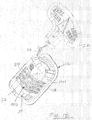
- the indicator 10 of the invention is intended to be snapped onto an inflator 12 to indicate the "ready" operating condition of the inflator 12.
- the firing lever 24 pops off the indicator 10 from the inflator 12, thereby indicating the "fired" inoperable operating condition.
- Inflators 12 come in a variety of shapes and sizes. It shall be understood, however, that the indicator 10 of the invention may be appropriately configured and dimensioned to fit a specific style of inflator 12. Accordingly, for the purpose of this detailed description of the indicator 10 of the invention, exemplary reference is made to the heat-sealable inflator 12 disclosed in U.S. Patent 7,475,711 , which includes a generally rectangular housing 14. The indicator 10 is accordingly configured and dimensioned to fit about the generally rectangular housing 14 of such an inflator 12.
- heat-sealable inflators 12 typically comprise a generally rectangular housing 14 with side walls 14W and having an integral peripheral flange 16 composed of a heat-sealable material such as polyurethane that may be heat-sealed to the inflatable article such as personal floatation devices, life rafts, and the like (not shown.)
- the inflator 12 is adapted to receive the threaded neck of a gas cylinder (shown in phantom in Fig. 1A as numeral 18) such that upon firing, gas from the gas cartridge 18 may flow through the inflator 12 and out its exhaust port 20 (see Fig. 3 ) into the inflatable article.
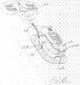
- Firing of the inflator 12 is accomplished by means of a firing lever 22 (see Fig. 2B ) to which is tethered a jerk handle 24 by means of a lanyard 26.
- the firing lever 22 comprises a generally L-shaped configuration having an upstanding arm 28 into which the lanyard 26 is inserted into and tightly and permanently secured such as by staking.
- the lower leg portion 30 of the firing lever 22 comprises a pivot hole through which a pivot pin 32 is inserted to allow the firing lever 22 to pivot about the pivot pin 32 upon jerking of the jerk handle 24.
- the lower leg portion 30 of the firing lever 22 includes a cam surface which is operatively designed to cam against a firing pin of an internal pierce pin assembly to fracture the frangible seal of the gas cartridge 18, whereupon gas from the gas cartridge 18 flows through the inflator 12 and out the exhaust port 20 into the article to be inflated.
- the inflator's housing 14 may include an upstanding side recess 22SR and a lower side recess 22LR into which the upstanding arm 28 and lower leg portion 30 of the firing lever 22 respectively lays into so that the upstanding arm 28 and lower leg portion 30 are substantially flush with the corresponding side wall and bottom wall of the housing.
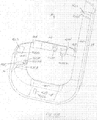
- indicator 10 comprises a generally rectangular configuration corresponding to the rectangular configuration of the housing 14. More particularly, indicator 10 comprises a generally U-shaped configuration defined by a long side wall 34 and a short side wall 36 joined together by a bottom wall 38 to form the U-shaped configuration.
- the long side wall 34 is configured and dimensioned to fully cover and therefore conceal the upstanding arm 28 of the firing lever 22 of the inflator.
- the bottom wall 38 of the indicator 10 is appropriately configured and dimensioned to cover and therefore conceal the lower leg portion 30 of the firing lever 22.
- a corner wall 34/38 interconnects the bottom of the long side wall 34 and the left portion of bottom wall 38 and a corner wall 38/36 interconnects the right portion of the bottom wall 38 and short side wall 36.
- the front edges of the long side wall 34, bottom wall 38 and short side wall 36 may include respective arcuate edge walls 34E, 38E and 36E.
- corner walls 34/38 and 38/36 may include respective arcuate edge walls 34/38E and 38/36E.
- the corner walls 34/38 and 38/36 coupled with the arcuate edge walls 34/38E, 38/36E, 34E, 38E and 36E more completely wrap around the corresponding rounded edges of the generally rectangular housing 14 of the inflator 12 to more completely conceal the firing lever 22 beneath.
- the side walls 34, 36 and 38 with their interconnecting corner walls 34/38 and 38/36 and arcuate edge walls 34/38E, 38/36E, 34E, 38E and 36E also more securely entrain the indicator 10 onto housing 14.
- the side walls 34 and 36 of the indicator 10 may be injection-molded in a slightly contracted configuration to increase the degree that the side walls 34 and 36 must be spread apart to snap onto the corresponding side walls of the housing 14 and impart a greater grasping grip on the housing 14.
- An optional bridge 40 composed of a thin material may be integrally formed during injection molding of the indicator 10 to span the distance between the edge walls 34E and 36E of the side walls 34 and 36.
- the bridge 40 more securely retains the side walls 34 and 36 about the corresponding side walls of the housing 14 of the inflator 12.
- the bridge 40 may be aligned with and extend into a corresponding slot 40S in the inflator's body, preferably substantially flush.
- the firing lever 22 upon firing of the inflator 12, the firing lever 22 is pivoted outwardly about the pivot pin 32 and forcibly pops the bridge 40 out of the slot 40S as the indicator 10 is popped-off of the inflator housing 14.
- the bridge 40 is fracturable either by being composed of a thin material or by having a scored notch 40N formed partly therethrough such that the bridge 40 forcibly fractures at the notch 40N and potentially at a thin, weakened point 40P when the firing lever 22 is pivoted outwardly about the pivot pin 32 to pop the bridge 40 out of the slot 40S.
- the fractured bridge 40 of a previously-spent indicator 10 provides a visual indication not to re-use it. Even if reuse is attempted, the previously-spent indicator 10 cannot be installed unless the firing lever 22 is reset to its ready condition tucked into the recesses 22SR and 22LR of the housing 14.
- the side walls 34 and 36 and the bridge 40 of the indicator 10 may be provided with integrally molded tabs 42 appropriately aligned and dimensioned to fit into corresponding pre-existing or specially-configured slots 44 in the inflator 12 to more securely retain the indicator 10 onto the housing 14.
- a tab 42L on the long side wall 34 of the indicator 10 may include an inwardly-oriented tab 42L that fits into the recess 22SR between the upper end of the upstanding arm 28 of the firing lever 22.
- the tab 42L may be provided with an angle 42LA to facilitate insertion into the recess 22SR.
- the short side wall 36 of the indicator 10 may include a inwardly-oriented tab 42S that is appropriately aligned and dimensioned to fit into a corresponding recess 14R formed in the side of the housing 14.
- Tab 42S likewise may include an angle 42 S A to facilitate insertion into the recess 22LR.
- the bottom wall 38 of the indicator 10 may include a inwardly-oriented tab 42B that is appropriately aligned and dimensioned to fit between the lower leg portion 30 of the firing lever 22 into the lower side recess 22LR.
- Tab 42B likewise may include an angle 42BA to facilitate insertion into the recess 22LR.
- tab 42C aligned with the corner of the housing 14 to fit into the space between the lower leg portion 30 of the firing lever 22 into the lower side recess 22LR at the point where the lower leg portion 30 begins to curve.
- the tab 42C may include an angle 42CA to facilitate insertion into the recess 22LR.
- the tab 42C many also include an upwardly extending hook 42CH, also with an angle 42CHA for ease in insertion, which hooks onto a lip 14L formed in the lower side recess 22LR.
- Inwardly extending tabs 42B1 and 42B2 may be provided along the bridge 40 to fit into the slot 40S formed in the front surface of the housing 14 to facilitate centering within the slot 402 and to increase the ease in which the bridge 40 is fractured at the scored notch 40N.
- tabs 42 coupled with the inherent resiliency of the material constituting the indicator 10, increases the degree that the side walls 34 and 36 must be spread apart to snap onto the corresponding side walls of the housing 14, but then assures that the indicator 10 will be held into place more securely, that is until the side walls 34 and 36 are forced apart by the firing lever 22 upon firing of the inflator 12.
- the firing lever 22 is colored red and the indicator 10 is colored green.
- the indicator 10 is snapped onto the housing 14 to fully cover and therefore conceal the red firing lever 22, the indicator 12 visually indicates from all directions an "armed” or “at ready” operable condition.
- the bridge 40 is fractured and the indicator 10 is popped-off of the housing 14 of the inflator 12. While in this "unarmed” or “fired” condition, the red firing lever 22 visually indicates from all directions that the inflator 12 is inoperable.
Landscapes
- Engineering & Computer Science (AREA)
- Mechanical Engineering (AREA)
- Ocean & Marine Engineering (AREA)
- Air Bags (AREA)
Claims (12)
- Indikator (10) für eine Aufblasvorrichtung (12), wobei die Aufblasvorrichtung einen Abzugshebel (22) umfasst, wobei der Abzugshebel (22) Folgendes umfasst:einen aufrechten Arm (28) und einen unteren Schenkelabschnitt (30), dadurch gekennzeichnet, dassder Indikator (10) eine lange Seitenwand (34) und eine kurze Seitenwand (36), die über eine Bodenwand (38) miteinander verbunden sind, um eine im Allgemeinen u-förmige Konfiguration auszubilden, umfasst,wobei die lange Seitenwand (34) dazu ausgelegt und dimensioniert ist, den aufrechten Arm (28) des Abzugshebels der Aufblasvorrichtung abzudecken und zu verdecken,wobei die Bodenwand (38) dazu ausgelegt und dimensioniert ist, den unteren Schenkelabschnitt (30) des Abzugshebels (22) abzudecken und zu verdecken.
- Indikator (10) für eine Aufblasvorrichtung (12) nach Anspruch 1, ferner eine Eckwand (34/38), die den Boden der langen Seitenwand (34) und einen linken Abschnitt der Bodenwand (38) miteinander verbindet, und eine Eckwand (38/36), die den rechten Abschnitt der Bodenwand (38) und die kurze Seitenwand (36) miteinander verbindet, umfassend.
- Indikator (10) für eine Aufblasvorrichtung (12) nach Anspruch 2, wobei Vorderkanten der langen Seitenwand (34), der Bodenwand (38) und der kurzen Seitenwand (36) entsprechende bogenförmige Kantenwände (34E; 38E, 36E) aufweisen, die dazu ausgelegt und dimensioniert sind, sich mehr um die Aufblasvorrichtung (12) zu wickeln und den Indikator (10) fester auf der Aufblasvorrichtung (12) zu verankern.
- Indikator (10) für eine Aufblasvorrichtung (12) nach Anspruch 2, wobei die Seitenwände (34; 36) in einer leicht zusammengezogenen Konfiguration spritzgegossen sind, um den Grad, den die Seitenwände (34; 36) auseinandergespreizt werden müssen, um auf die Aufblasvorrichtung (12) aufzuschnappen, zu erhöhen und einen festeren Griff auf die Aufblasvorrichtung (12) auszuüben.
- Indikator (10) für eine Aufblasvorrichtung (12) nach Anspruch 1, ferner eine Brücke (40) umfassend, die einen Abstand zwischen den Seitenwänden (34; 36) überspannt.
- Indikator (10) für eine Aufblasvorrichtung (12) nach Anspruch 1, ferner mindestens eine Lasche (42) umfassend, die in einen zugehörigen Schlitz (44) in der Aufblasvorrichtung (12) passt, um den Indikator (10) fester auf der Aufblasvorrichtung (12) zu halten.
- Indikator (10) für eine Aufblasvorrichtung (12) nach Anspruch 6, wobei die Lasche (42) auf der langen Seitenwand (34) positioniert ist.
- Indikator (10) für eine Aufblasvorrichtung (12) nach Anspruch 6, wobei die Lasche (42) auf der kurzen Seitenwand (36) positioniert ist.
- Indikator (10) für eine Aufblasvorrichtung (12) nach Anspruch 6, wobei die Lasche (42) auf der Bodenwand (38) positioniert ist.
- Indikator (10) für eine Aufblasvorrichtung (12) nach Anspruch 6, wobei die Lasche (42) auf einer Ecke der Bodenwand (38) positioniert ist und einen Haken (42C) aufweist, der sich in eine in der Aussparung (22LR) auf der unteren Seite ausgebildete Lippe einhakt.
- Indikator (10) für eine Aufblasvorrichtung (12) nach Anspruch 6, wobei die Lasche (42) einen Winkel (42CHA) umfasst, um das Einsetzen zu ermöglichen.
- Indikator (10) für eine Aufblasvorrichtung (12) nach Anspruch 1, wobei der Abzugshebel (22) rot ist und der Indikator (10) grün ist, sodass, wenn der grüne Indikator (10) auf der Aufblasvorrichtung (12) aufgeschnappt ist, um den roten Abzugshebel (22) abzudecken und zu verdecken, der Indikator (10) visuell aus allen Richtungen einen Betriebszustand "scharf" oder "bereit" anzeigt und sodass beim Abziehen der Aufblasvorrichtung (12) der Indikator (10) von der Aufblasvorrichtung (12) abgestoßen wird und einen Zustand "nicht scharf" oder "abgezogen" freilegt.
Applications Claiming Priority (2)
| Application Number | Priority Date | Filing Date | Title |
|---|---|---|---|
| US201562136684P | 2015-03-23 | 2015-03-23 | |
| PCT/US2016/023795 WO2016154324A1 (en) | 2015-03-23 | 2016-03-23 | Indicator for manual inflator |
Publications (3)
| Publication Number | Publication Date |
|---|---|
| EP3274253A1 EP3274253A1 (de) | 2018-01-31 |
| EP3274253A4 EP3274253A4 (de) | 2019-02-27 |
| EP3274253B1 true EP3274253B1 (de) | 2019-09-11 |
Family
ID=56973978
Family Applications (1)
| Application Number | Title | Priority Date | Filing Date |
|---|---|---|---|
| EP16769617.8A Active EP3274253B1 (de) | 2015-03-23 | 2016-03-23 | Indikator für manuelle aufblasvorrichtung |
Country Status (7)
| Country | Link |
|---|---|
| US (1) | US10017231B2 (de) |
| EP (1) | EP3274253B1 (de) |
| JP (1) | JP6670321B2 (de) |
| AU (1) | AU2016235235B2 (de) |
| CA (1) | CA2980724C (de) |
| WO (1) | WO2016154324A1 (de) |
| ZA (1) | ZA201706537B (de) |
Families Citing this family (22)
| Publication number | Priority date | Publication date | Assignee | Title |
|---|---|---|---|---|
| US10441761B2 (en) | 2016-07-01 | 2019-10-15 | Boston Scientific Scimed, Inc. | Delivery devices and methods |
| JP7126506B2 (ja) | 2017-01-10 | 2022-08-26 | ボストン サイエンティフィック サイムド,インコーポレイテッド | 粉末薬剤を送達するための装置および方法 |
| GB2559773B (en) * | 2017-02-17 | 2022-03-23 | Survitec Group Ltd | Survival systems |
| CN111587129A (zh) | 2018-01-12 | 2020-08-25 | 波士顿科学国际有限公司 | 实现止血的粉末 |
| US11766546B2 (en) | 2018-01-31 | 2023-09-26 | Boston Scientific Scimed, Inc. | Apparatuses and methods for delivering powdered agents |
| JP2022503410A (ja) * | 2018-06-13 | 2022-01-12 | ハルキー-ロバーツ・コーポレーション | 使い捨てインフレータ |
| US11180230B2 (en) * | 2018-06-13 | 2021-11-23 | Halkey-Roberts Corporation | Disposable Inflator |
| JP7447100B2 (ja) | 2018-10-02 | 2024-03-11 | ボストン サイエンティフィック サイムド,インコーポレイテッド | 粉末剤を流動化して送達するための装置 |
| EP4579371A3 (de) | 2018-10-02 | 2025-12-24 | Boston Scientific Scimed, Inc. | Vorrichtungen zur fluidisierung und abgabe eines pulverförmigen mittels |
| MX2021009409A (es) | 2019-02-06 | 2021-12-10 | Boost Ideas Llc | Prenda de vestir de seguridad en agua, aparato y métodos relacionados. |
| US11918780B2 (en) | 2019-12-03 | 2024-03-05 | Boston Scientific Scimed, Inc. | Agent administering medical device |
| EP4309564B1 (de) | 2019-12-03 | 2026-01-28 | Boston Scientific Scimed, Inc. | Medizinische systeme zur wirkstofffreisetzung |
| CN121512581A (zh) | 2019-12-03 | 2026-02-13 | 波士顿科学国际有限公司 | 用于药物输送的医疗装置及相关使用方法 |
| US12053169B2 (en) | 2019-12-03 | 2024-08-06 | Boston Scientific Scimed, Inc. | Devices and methods for delivering powdered agents |
| US12370353B2 (en) | 2019-12-20 | 2025-07-29 | Boston Scientific Scimed, Inc. | Agent delivery device |
| CN114901157B (zh) | 2020-01-06 | 2025-08-12 | 波士顿科学国际有限公司 | 药剂输送系统 |
| US12465698B2 (en) | 2020-01-06 | 2025-11-11 | Boston Scientific Scimed, Inc. | Devices and methods for delivering powdered agents |
| EP4106826A1 (de) | 2020-02-18 | 2022-12-28 | Boston Scientific Scimed, Inc. | Hämostatische zusammensetzungen und zugehörige verfahren |
| EP4076213B1 (de) | 2020-03-06 | 2025-08-27 | Boston Scientific Scimed, Inc. | Vorrichtungen zur abgabe von pulverförmigen mitteln |
| AU2021241588B2 (en) | 2020-03-24 | 2026-01-15 | Boston Scientific Scimed, Inc. | Agent delivery systems and methods of using the same |
| EP4135784A1 (de) | 2020-04-17 | 2023-02-22 | Boston Scientific Scimed, Inc. | Hämostatische zusammensetzungen und zugehörige verfahren |
| US12502488B2 (en) | 2020-08-19 | 2025-12-23 | Boston Scientific Scimed, Inc. | Delivery device and methods of use |
Family Cites Families (49)
| Publication number | Priority date | Publication date | Assignee | Title |
|---|---|---|---|---|
| US3059814A (en) | 1959-11-09 | 1962-10-23 | Eugene E Poncel | Actuator for emergency water equipment |
| US3091782A (en) | 1962-06-11 | 1963-06-04 | Aerotec Ind Inc | Apparatus for flotation of articles on water |
| US3426942A (en) | 1967-07-31 | 1969-02-11 | Jay El Products Inc | Water-responsive energizing apparatus |
| US3579964A (en) | 1969-07-01 | 1971-05-25 | Us Navy | Squib-powered automatic inflation device |
| GB1360212A (en) | 1970-12-21 | 1974-07-17 | Martin J | Survival or like packs particularly suitable for airmen |
| US3702014A (en) | 1971-02-19 | 1972-11-07 | Us Navy | Squib ejected marker buoy |
| US3754731A (en) | 1972-01-18 | 1973-08-28 | Halkey Roberts Corp | Inflation manifold valve and flange assembly |
| US3746285A (en) * | 1972-02-25 | 1973-07-17 | J Mango | Rescue balloon kit |
| US3809288A (en) | 1973-03-26 | 1974-05-07 | G Mackal | Inflation manifold |
| US3997079A (en) | 1974-04-17 | 1976-12-14 | Wolfgang Niemann | Automatic inflating device for lifesaving devices |
| US3910457A (en) | 1974-05-06 | 1975-10-07 | Koch & Sons Inc H | Electronic water-activated parachute release and life vest inflator |
| US4216182A (en) | 1977-02-01 | 1980-08-05 | Judd Edward A | Inflation manifold, method of and apparatus for heading plastic safety pins therein |
| US4223805A (en) * | 1978-08-04 | 1980-09-23 | Mackal Glenn H | Automatic inflator |
| US4267944A (en) | 1978-08-07 | 1981-05-19 | Mackal Glenn H | Automatic inflator |
| US4260075A (en) | 1978-08-01 | 1981-04-07 | Mackal Glenn H | Automatic inflator |
| US4382231A (en) | 1980-11-17 | 1983-05-03 | Conax Corporation | Fluid conductivity sensor |
| US4513248A (en) | 1980-11-17 | 1985-04-23 | Conax Corporation | Fluid conductivity sensor |
| US4436159A (en) | 1981-05-01 | 1984-03-13 | Kidde, Inc. | Manual/electric activated squib actuated discharge valve for fire extinguishers |
| US4416393A (en) * | 1981-09-23 | 1983-11-22 | Halkey-Roberts Corporation | Inflator guard |
| US4482333A (en) * | 1982-04-30 | 1984-11-13 | Geri Engineering, Inc. | Automatic inflation system |
| US4627823A (en) | 1984-07-23 | 1986-12-09 | Glenn Mackal | Safety latched automatic actuator and throwable personal flotation assembly |
| US4894036A (en) * | 1988-08-08 | 1990-01-16 | Switlik Parachute Company, Inc. | Inflator assembly for life vests |
| US5026310A (en) | 1990-02-28 | 1991-06-25 | Halkey-Roberts Corporation | Electric autoinflator |
| US5076468A (en) | 1990-02-28 | 1991-12-31 | Halkey-Roberts Corporation | Squib inflator adaptor |
| US5058932A (en) | 1990-05-14 | 1991-10-22 | Mackal Glenn H | Annular clip for inflation manifold |
| US5058933A (en) | 1990-05-14 | 1991-10-22 | Mackal Glenn H | Rotation and retraction-resistant manifold having integral flange |
| US5080402A (en) | 1990-05-14 | 1992-01-14 | Mackal Glenn H | Apparatus for joining an inflation manifold to an inflatable article |
| US5029367A (en) * | 1990-05-14 | 1991-07-09 | Mackal Glenn H | Protective cover and pulled lanyard indicator for an inflator |
| US5271525A (en) * | 1992-02-18 | 1993-12-21 | Petrie Ross J | Inflation manifold |
| US5400922A (en) | 1992-07-14 | 1995-03-28 | Halkey-Roberts Corporation | Electric autoinflator |
| US5509576A (en) | 1992-07-14 | 1996-04-23 | Halkey-Roberts Corporation | Electric autoinflator |
| US5333656A (en) * | 1993-05-26 | 1994-08-02 | Mackal Glenn H | Auto inflator having dissolvable element under low pressure |
| US5564478A (en) * | 1994-09-02 | 1996-10-15 | Halkey-Roberts Corporation | Heat sealable inflator |
| US5694986A (en) * | 1995-02-07 | 1997-12-09 | Halkey-Roberts Corporation | Automatic actuator with apertured housing and safety indicator |
| US5601124A (en) | 1995-02-07 | 1997-02-11 | Halkey-Roberts Corporation | Autoinflator with apertured housing |
| US5775358A (en) | 1995-11-03 | 1998-07-07 | Halkey-Roberts Corporation | Indicator for compressed gas cartridge |
| DE69616979T2 (de) * | 1996-04-25 | 2002-06-06 | Halkey-Roberts Corp., St. Petersburg | Heisssiegelfähiges Aufblasgerät |
| US5643030A (en) * | 1996-07-17 | 1997-07-01 | Brown; Dennis | Gas cartridge safety inflator apparatus |
| US6422420B1 (en) * | 2001-05-15 | 2002-07-23 | Dennis Brown | Compressed gas safety inflator for life vests, life rafts and the like |
| US6589087B2 (en) | 2001-09-07 | 2003-07-08 | Halkey-Roberts Corporation | Automatic inflator with status indicator |
| US7056179B2 (en) * | 2002-05-05 | 2006-06-06 | Courtney William L | Combination inflator and manifold assembly |
| WO2004041363A2 (en) * | 2002-11-01 | 2004-05-21 | Courtney William L | Variably configured inflatable personal flotation device also serving as an emergency distress marker |
| EP1662938A4 (de) * | 2003-09-08 | 2006-09-20 | Halkey Roberts Corp | Zusammenbaubarer reissgriff für gasgeneratoren |
| GB0328567D0 (en) | 2003-12-10 | 2004-01-14 | Ibm | A system for information capture |
| US7475711B2 (en) * | 2006-05-16 | 2009-01-13 | Halkey-Roberts Corporation | Heat sealable inflator |
| US7854347B2 (en) * | 2006-06-02 | 2010-12-21 | Hudson Wang | Manual gas inflator |
| NZ595462A (en) * | 2009-04-15 | 2014-04-30 | Halkey Roberts Corp | Manual inflator with cylinder connector and status indicator |
| EP2598397A4 (de) * | 2010-07-30 | 2018-02-07 | Sagittarius Sporting Goods, Co. Ltd. | Automatischer/manueller gasgenerator mit doppelpunktanzeige |
| JP5752551B2 (ja) * | 2011-09-30 | 2015-07-22 | 藤倉航装株式会社 | 膨張装置 |
-
2016
- 2016-03-23 JP JP2017549694A patent/JP6670321B2/ja active Active
- 2016-03-23 AU AU2016235235A patent/AU2016235235B2/en active Active
- 2016-03-23 US US15/078,693 patent/US10017231B2/en active Active
- 2016-03-23 CA CA2980724A patent/CA2980724C/en active Active
- 2016-03-23 EP EP16769617.8A patent/EP3274253B1/de active Active
- 2016-03-23 WO PCT/US2016/023795 patent/WO2016154324A1/en not_active Ceased
-
2017
- 2017-09-28 ZA ZA2017/06537A patent/ZA201706537B/en unknown
Non-Patent Citations (1)
| Title |
|---|
| None * |
Also Published As
| Publication number | Publication date |
|---|---|
| ZA201706537B (en) | 2019-08-28 |
| EP3274253A4 (de) | 2019-02-27 |
| NZ736201A (en) | 2020-10-30 |
| JP6670321B2 (ja) | 2020-03-18 |
| EP3274253A1 (de) | 2018-01-31 |
| CA2980724C (en) | 2021-05-11 |
| JP2018509340A (ja) | 2018-04-05 |
| US10017231B2 (en) | 2018-07-10 |
| US20160280342A1 (en) | 2016-09-29 |
| WO2016154324A1 (en) | 2016-09-29 |
| AU2016235235B2 (en) | 2019-03-14 |
| CA2980724A1 (en) | 2016-09-29 |
| AU2016235235A1 (en) | 2017-10-12 |
Similar Documents
| Publication | Publication Date | Title |
|---|---|---|
| EP3274253B1 (de) | Indikator für manuelle aufblasvorrichtung | |
| US8360276B2 (en) | Manual inflator with cylinder connector and status indicator | |
| EP1432610B1 (de) | Automatische aufblasvorrichtung mit statusanzeige | |
| JP2018509340A5 (de) | ||
| US11180230B2 (en) | Disposable Inflator | |
| US10730595B2 (en) | Disposable inflator | |
| US5694986A (en) | Automatic actuator with apertured housing and safety indicator | |
| CA2679777A1 (en) | Party balloon with illumination device | |
| US4441639A (en) | Quick-release and quick-deploy container for emergency equipment | |
| NZ736201B2 (en) | Indicator for manual inflator | |
| US4416393A (en) | Inflator guard | |
| US3844356A (en) | Fire extinguisher | |
| US4349960A (en) | Raft knife | |
| US5029367A (en) | Protective cover and pulled lanyard indicator for an inflator | |
| AU2012261490B2 (en) | Automatic inflator with status indicator | |
| US20120042965A1 (en) | Apparatus and Method for Mounting an Inflator, Exhaust Valve or Relief Valve Interiorly of an Inflatable Article | |
| HK1167375A (en) | Manual inflator with cylinder connector and status indicator | |
| HK1167375B (en) | Manual inflator with cylinder connector and status indicator | |
| JP5038383B2 (ja) | 牛の鼻輪 | |
| AU2002332819A1 (en) | Automatic inflator with status indicator |
Legal Events
| Date | Code | Title | Description |
|---|---|---|---|
| STAA | Information on the status of an ep patent application or granted ep patent |
Free format text: STATUS: THE INTERNATIONAL PUBLICATION HAS BEEN MADE |
|
| PUAI | Public reference made under article 153(3) epc to a published international application that has entered the european phase |
Free format text: ORIGINAL CODE: 0009012 |
|
| STAA | Information on the status of an ep patent application or granted ep patent |
Free format text: STATUS: REQUEST FOR EXAMINATION WAS MADE |
|
| 17P | Request for examination filed |
Effective date: 20170926 |
|
| AK | Designated contracting states |
Kind code of ref document: A1 Designated state(s): AL AT BE BG CH CY CZ DE DK EE ES FI FR GB GR HR HU IE IS IT LI LT LU LV MC MK MT NL NO PL PT RO RS SE SI SK SM TR |
|
| AX | Request for extension of the european patent |
Extension state: BA ME |
|
| DAV | Request for validation of the european patent (deleted) | ||
| DAX | Request for extension of the european patent (deleted) | ||
| A4 | Supplementary search report drawn up and despatched |
Effective date: 20190130 |
|
| RIC1 | Information provided on ipc code assigned before grant |
Ipc: B63C 9/00 20060101ALI20190124BHEP Ipc: B63B 7/00 20060101ALI20190124BHEP Ipc: B63C 9/02 20060101ALI20190124BHEP Ipc: B65B 1/04 20060101ALI20190124BHEP Ipc: B63C 9/19 20060101ALI20190124BHEP Ipc: B63C 9/18 20060101AFI20190124BHEP |
|
| GRAP | Despatch of communication of intention to grant a patent |
Free format text: ORIGINAL CODE: EPIDOSNIGR1 |
|
| STAA | Information on the status of an ep patent application or granted ep patent |
Free format text: STATUS: GRANT OF PATENT IS INTENDED |
|
| INTG | Intention to grant announced |
Effective date: 20190402 |
|
| GRAS | Grant fee paid |
Free format text: ORIGINAL CODE: EPIDOSNIGR3 |
|
| GRAA | (expected) grant |
Free format text: ORIGINAL CODE: 0009210 |
|
| STAA | Information on the status of an ep patent application or granted ep patent |
Free format text: STATUS: THE PATENT HAS BEEN GRANTED |
|
| AK | Designated contracting states |
Kind code of ref document: B1 Designated state(s): AL AT BE BG CH CY CZ DE DK EE ES FI FR GB GR HR HU IE IS IT LI LT LU LV MC MK MT NL NO PL PT RO RS SE SI SK SM TR |
|
| REG | Reference to a national code |
Ref country code: GB Ref legal event code: FG4D |
|
| REG | Reference to a national code |
Ref country code: CH Ref legal event code: EP |
|
| REG | Reference to a national code |
Ref country code: AT Ref legal event code: REF Ref document number: 1178114 Country of ref document: AT Kind code of ref document: T Effective date: 20190915 |
|
| REG | Reference to a national code |
Ref country code: DE Ref legal event code: R096 Ref document number: 602016020494 Country of ref document: DE Ref country code: IE Ref legal event code: FG4D |
|
| REG | Reference to a national code |
Ref country code: NL Ref legal event code: MP Effective date: 20190911 |
|
| REG | Reference to a national code |
Ref country code: LT Ref legal event code: MG4D |
|
| PG25 | Lapsed in a contracting state [announced via postgrant information from national office to epo] |
Ref country code: SE Free format text: LAPSE BECAUSE OF FAILURE TO SUBMIT A TRANSLATION OF THE DESCRIPTION OR TO PAY THE FEE WITHIN THE PRESCRIBED TIME-LIMIT Effective date: 20190911 Ref country code: NO Free format text: LAPSE BECAUSE OF FAILURE TO SUBMIT A TRANSLATION OF THE DESCRIPTION OR TO PAY THE FEE WITHIN THE PRESCRIBED TIME-LIMIT Effective date: 20191211 Ref country code: FI Free format text: LAPSE BECAUSE OF FAILURE TO SUBMIT A TRANSLATION OF THE DESCRIPTION OR TO PAY THE FEE WITHIN THE PRESCRIBED TIME-LIMIT Effective date: 20190911 Ref country code: HR Free format text: LAPSE BECAUSE OF FAILURE TO SUBMIT A TRANSLATION OF THE DESCRIPTION OR TO PAY THE FEE WITHIN THE PRESCRIBED TIME-LIMIT Effective date: 20190911 Ref country code: BG Free format text: LAPSE BECAUSE OF FAILURE TO SUBMIT A TRANSLATION OF THE DESCRIPTION OR TO PAY THE FEE WITHIN THE PRESCRIBED TIME-LIMIT Effective date: 20191211 Ref country code: LT Free format text: LAPSE BECAUSE OF FAILURE TO SUBMIT A TRANSLATION OF THE DESCRIPTION OR TO PAY THE FEE WITHIN THE PRESCRIBED TIME-LIMIT Effective date: 20190911 |
|
| PG25 | Lapsed in a contracting state [announced via postgrant information from national office to epo] |
Ref country code: RS Free format text: LAPSE BECAUSE OF FAILURE TO SUBMIT A TRANSLATION OF THE DESCRIPTION OR TO PAY THE FEE WITHIN THE PRESCRIBED TIME-LIMIT Effective date: 20190911 Ref country code: LV Free format text: LAPSE BECAUSE OF FAILURE TO SUBMIT A TRANSLATION OF THE DESCRIPTION OR TO PAY THE FEE WITHIN THE PRESCRIBED TIME-LIMIT Effective date: 20190911 Ref country code: AL Free format text: LAPSE BECAUSE OF FAILURE TO SUBMIT A TRANSLATION OF THE DESCRIPTION OR TO PAY THE FEE WITHIN THE PRESCRIBED TIME-LIMIT Effective date: 20190911 Ref country code: ES Free format text: LAPSE BECAUSE OF FAILURE TO SUBMIT A TRANSLATION OF THE DESCRIPTION OR TO PAY THE FEE WITHIN THE PRESCRIBED TIME-LIMIT Effective date: 20190911 Ref country code: GR Free format text: LAPSE BECAUSE OF FAILURE TO SUBMIT A TRANSLATION OF THE DESCRIPTION OR TO PAY THE FEE WITHIN THE PRESCRIBED TIME-LIMIT Effective date: 20191212 |
|
| REG | Reference to a national code |
Ref country code: AT Ref legal event code: MK05 Ref document number: 1178114 Country of ref document: AT Kind code of ref document: T Effective date: 20190911 |
|
| PG25 | Lapsed in a contracting state [announced via postgrant information from national office to epo] |
Ref country code: PL Free format text: LAPSE BECAUSE OF FAILURE TO SUBMIT A TRANSLATION OF THE DESCRIPTION OR TO PAY THE FEE WITHIN THE PRESCRIBED TIME-LIMIT Effective date: 20190911 Ref country code: NL Free format text: LAPSE BECAUSE OF FAILURE TO SUBMIT A TRANSLATION OF THE DESCRIPTION OR TO PAY THE FEE WITHIN THE PRESCRIBED TIME-LIMIT Effective date: 20190911 Ref country code: PT Free format text: LAPSE BECAUSE OF FAILURE TO SUBMIT A TRANSLATION OF THE DESCRIPTION OR TO PAY THE FEE WITHIN THE PRESCRIBED TIME-LIMIT Effective date: 20200113 Ref country code: RO Free format text: LAPSE BECAUSE OF FAILURE TO SUBMIT A TRANSLATION OF THE DESCRIPTION OR TO PAY THE FEE WITHIN THE PRESCRIBED TIME-LIMIT Effective date: 20190911 Ref country code: AT Free format text: LAPSE BECAUSE OF FAILURE TO SUBMIT A TRANSLATION OF THE DESCRIPTION OR TO PAY THE FEE WITHIN THE PRESCRIBED TIME-LIMIT Effective date: 20190911 Ref country code: IT Free format text: LAPSE BECAUSE OF FAILURE TO SUBMIT A TRANSLATION OF THE DESCRIPTION OR TO PAY THE FEE WITHIN THE PRESCRIBED TIME-LIMIT Effective date: 20190911 Ref country code: EE Free format text: LAPSE BECAUSE OF FAILURE TO SUBMIT A TRANSLATION OF THE DESCRIPTION OR TO PAY THE FEE WITHIN THE PRESCRIBED TIME-LIMIT Effective date: 20190911 |
|
| PG25 | Lapsed in a contracting state [announced via postgrant information from national office to epo] |
Ref country code: SM Free format text: LAPSE BECAUSE OF FAILURE TO SUBMIT A TRANSLATION OF THE DESCRIPTION OR TO PAY THE FEE WITHIN THE PRESCRIBED TIME-LIMIT Effective date: 20190911 Ref country code: CZ Free format text: LAPSE BECAUSE OF FAILURE TO SUBMIT A TRANSLATION OF THE DESCRIPTION OR TO PAY THE FEE WITHIN THE PRESCRIBED TIME-LIMIT Effective date: 20190911 Ref country code: SK Free format text: LAPSE BECAUSE OF FAILURE TO SUBMIT A TRANSLATION OF THE DESCRIPTION OR TO PAY THE FEE WITHIN THE PRESCRIBED TIME-LIMIT Effective date: 20190911 Ref country code: IS Free format text: LAPSE BECAUSE OF FAILURE TO SUBMIT A TRANSLATION OF THE DESCRIPTION OR TO PAY THE FEE WITHIN THE PRESCRIBED TIME-LIMIT Effective date: 20200224 |
|
| REG | Reference to a national code |
Ref country code: DE Ref legal event code: R097 Ref document number: 602016020494 Country of ref document: DE |
|
| PLBE | No opposition filed within time limit |
Free format text: ORIGINAL CODE: 0009261 |
|
| STAA | Information on the status of an ep patent application or granted ep patent |
Free format text: STATUS: NO OPPOSITION FILED WITHIN TIME LIMIT |
|
| PG2D | Information on lapse in contracting state deleted |
Ref country code: IS |
|
| PG25 | Lapsed in a contracting state [announced via postgrant information from national office to epo] |
Ref country code: DK Free format text: LAPSE BECAUSE OF FAILURE TO SUBMIT A TRANSLATION OF THE DESCRIPTION OR TO PAY THE FEE WITHIN THE PRESCRIBED TIME-LIMIT Effective date: 20190911 Ref country code: IS Free format text: LAPSE BECAUSE OF FAILURE TO SUBMIT A TRANSLATION OF THE DESCRIPTION OR TO PAY THE FEE WITHIN THE PRESCRIBED TIME-LIMIT Effective date: 20200112 |
|
| 26N | No opposition filed |
Effective date: 20200615 |
|
| PG25 | Lapsed in a contracting state [announced via postgrant information from national office to epo] |
Ref country code: SI Free format text: LAPSE BECAUSE OF FAILURE TO SUBMIT A TRANSLATION OF THE DESCRIPTION OR TO PAY THE FEE WITHIN THE PRESCRIBED TIME-LIMIT Effective date: 20190911 |
|
| PG25 | Lapsed in a contracting state [announced via postgrant information from national office to epo] |
Ref country code: TR Free format text: LAPSE BECAUSE OF FAILURE TO SUBMIT A TRANSLATION OF THE DESCRIPTION OR TO PAY THE FEE WITHIN THE PRESCRIBED TIME-LIMIT Effective date: 20190911 Ref country code: CY Free format text: LAPSE BECAUSE OF FAILURE TO SUBMIT A TRANSLATION OF THE DESCRIPTION OR TO PAY THE FEE WITHIN THE PRESCRIBED TIME-LIMIT Effective date: 20190911 |
|
| PG25 | Lapsed in a contracting state [announced via postgrant information from national office to epo] |
Ref country code: MK Free format text: LAPSE BECAUSE OF FAILURE TO SUBMIT A TRANSLATION OF THE DESCRIPTION OR TO PAY THE FEE WITHIN THE PRESCRIBED TIME-LIMIT Effective date: 20190911 |
|
| PGFP | Annual fee paid to national office [announced via postgrant information from national office to epo] |
Ref country code: MC Payment date: 20240306 Year of fee payment: 9 |
|
| PGFP | Annual fee paid to national office [announced via postgrant information from national office to epo] |
Ref country code: MT Payment date: 20240301 Year of fee payment: 9 |
|
| PGFP | Annual fee paid to national office [announced via postgrant information from national office to epo] |
Ref country code: CH Payment date: 20250401 Year of fee payment: 10 |
|
| PG25 | Lapsed in a contracting state [announced via postgrant information from national office to epo] |
Ref country code: MC Free format text: LAPSE BECAUSE OF NON-PAYMENT OF DUE FEES Effective date: 20250331 |
|
| REG | Reference to a national code |
Ref country code: CH Ref legal event code: U11 Free format text: ST27 STATUS EVENT CODE: U-0-0-U10-U11 (AS PROVIDED BY THE NATIONAL OFFICE) Effective date: 20260401 |
|
| PGFP | Annual fee paid to national office [announced via postgrant information from national office to epo] |
Ref country code: GB Payment date: 20260324 Year of fee payment: 11 |
|
| PGFP | Annual fee paid to national office [announced via postgrant information from national office to epo] |
Ref country code: DE Payment date: 20260319 Year of fee payment: 11 Ref country code: IE Payment date: 20260319 Year of fee payment: 11 |
|
| PGFP | Annual fee paid to national office [announced via postgrant information from national office to epo] |
Ref country code: LU Payment date: 20260319 Year of fee payment: 11 Ref country code: BE Payment date: 20260319 Year of fee payment: 11 |
|
| PGFP | Annual fee paid to national office [announced via postgrant information from national office to epo] |
Ref country code: FR Payment date: 20260320 Year of fee payment: 11 |