EP3274590B1 - Verfahren zur regelung einer verdichtersanlage und verdichtersanlage - Google Patents
Verfahren zur regelung einer verdichtersanlage und verdichtersanlage Download PDFInfo
- Publication number
- EP3274590B1 EP3274590B1 EP16708269.2A EP16708269A EP3274590B1 EP 3274590 B1 EP3274590 B1 EP 3274590B1 EP 16708269 A EP16708269 A EP 16708269A EP 3274590 B1 EP3274590 B1 EP 3274590B1
- Authority
- EP
- European Patent Office
- Prior art keywords
- liquid
- stream
- compressor
- discharge
- pressure ratio
- Prior art date
- Legal status (The legal status is an assumption and is not a legal conclusion. Google has not performed a legal analysis and makes no representation as to the accuracy of the status listed.)
- Active
Links
Images


Classifications
-
- F—MECHANICAL ENGINEERING; LIGHTING; HEATING; WEAPONS; BLASTING
- F04—POSITIVE - DISPLACEMENT MACHINES FOR LIQUIDS; PUMPS FOR LIQUIDS OR ELASTIC FLUIDS
- F04D—NON-POSITIVE-DISPLACEMENT PUMPS
- F04D27/00—Control, e.g. regulation, of pumps, pumping installations or pumping systems specially adapted for elastic fluids
- F04D27/001—Testing thereof; Determination or simulation of flow characteristics; Stall or surge detection, e.g. condition monitoring
-
- F—MECHANICAL ENGINEERING; LIGHTING; HEATING; WEAPONS; BLASTING
- F04—POSITIVE - DISPLACEMENT MACHINES FOR LIQUIDS; PUMPS FOR LIQUIDS OR ELASTIC FLUIDS
- F04D—NON-POSITIVE-DISPLACEMENT PUMPS
- F04D27/00—Control, e.g. regulation, of pumps, pumping installations or pumping systems specially adapted for elastic fluids
- F04D27/02—Surge control
-
- F—MECHANICAL ENGINEERING; LIGHTING; HEATING; WEAPONS; BLASTING
- F04—POSITIVE - DISPLACEMENT MACHINES FOR LIQUIDS; PUMPS FOR LIQUIDS OR ELASTIC FLUIDS
- F04D—NON-POSITIVE-DISPLACEMENT PUMPS
- F04D17/00—Radial-flow pumps, e.g. centrifugal pumps; Helico-centrifugal pumps
- F04D17/08—Centrifugal pumps
- F04D17/10—Centrifugal pumps for compressing or evacuating
-
- F—MECHANICAL ENGINEERING; LIGHTING; HEATING; WEAPONS; BLASTING
- F04—POSITIVE - DISPLACEMENT MACHINES FOR LIQUIDS; PUMPS FOR LIQUIDS OR ELASTIC FLUIDS
- F04D—NON-POSITIVE-DISPLACEMENT PUMPS
- F04D25/00—Pumping installations or systems
- F04D25/02—Units comprising pumps and their driving means
-
- F—MECHANICAL ENGINEERING; LIGHTING; HEATING; WEAPONS; BLASTING
- F04—POSITIVE - DISPLACEMENT MACHINES FOR LIQUIDS; PUMPS FOR LIQUIDS OR ELASTIC FLUIDS
- F04D—NON-POSITIVE-DISPLACEMENT PUMPS
- F04D29/00—Details, component parts, or accessories
- F04D29/70—Suction grids; Strainers; Dust separation; Cleaning
- F04D29/701—Suction grids; Strainers; Dust separation; Cleaning especially adapted for elastic fluid pumps
- F04D29/705—Adding liquids
-
- F—MECHANICAL ENGINEERING; LIGHTING; HEATING; WEAPONS; BLASTING
- F04—POSITIVE - DISPLACEMENT MACHINES FOR LIQUIDS; PUMPS FOR LIQUIDS OR ELASTIC FLUIDS
- F04D—NON-POSITIVE-DISPLACEMENT PUMPS
- F04D31/00—Pumping liquids and elastic fluids at the same time
-
- F—MECHANICAL ENGINEERING; LIGHTING; HEATING; WEAPONS; BLASTING
- F04—POSITIVE - DISPLACEMENT MACHINES FOR LIQUIDS; PUMPS FOR LIQUIDS OR ELASTIC FLUIDS
- F04D—NON-POSITIVE-DISPLACEMENT PUMPS
- F04D17/00—Radial-flow pumps, e.g. centrifugal pumps; Helico-centrifugal pumps
- F04D17/08—Centrifugal pumps
- F04D17/10—Centrifugal pumps for compressing or evacuating
- F04D17/12—Multi-stage pumps
-
- F—MECHANICAL ENGINEERING; LIGHTING; HEATING; WEAPONS; BLASTING
- F05—INDEXING SCHEMES RELATING TO ENGINES OR PUMPS IN VARIOUS SUBCLASSES OF CLASSES F01-F04
- F05D—INDEXING SCHEME FOR ASPECTS RELATING TO NON-POSITIVE-DISPLACEMENT MACHINES OR ENGINES, GAS-TURBINES OR JET-PROPULSION PLANTS
- F05D2270/00—Control
- F05D2270/01—Purpose of the control system
- F05D2270/10—Purpose of the control system to cope with, or avoid, compressor flow instabilities
- F05D2270/101—Compressor surge or stall
-
- F—MECHANICAL ENGINEERING; LIGHTING; HEATING; WEAPONS; BLASTING
- F05—INDEXING SCHEMES RELATING TO ENGINES OR PUMPS IN VARIOUS SUBCLASSES OF CLASSES F01-F04
- F05D—INDEXING SCHEME FOR ASPECTS RELATING TO NON-POSITIVE-DISPLACEMENT MACHINES OR ENGINES, GAS-TURBINES OR JET-PROPULSION PLANTS
- F05D2270/00—Control
- F05D2270/30—Control parameters, e.g. input parameters
- F05D2270/301—Pressure
- F05D2270/3011—Inlet pressure
-
- F—MECHANICAL ENGINEERING; LIGHTING; HEATING; WEAPONS; BLASTING
- F05—INDEXING SCHEMES RELATING TO ENGINES OR PUMPS IN VARIOUS SUBCLASSES OF CLASSES F01-F04
- F05D—INDEXING SCHEME FOR ASPECTS RELATING TO NON-POSITIVE-DISPLACEMENT MACHINES OR ENGINES, GAS-TURBINES OR JET-PROPULSION PLANTS
- F05D2270/00—Control
- F05D2270/30—Control parameters, e.g. input parameters
- F05D2270/301—Pressure
- F05D2270/3013—Outlet pressure
-
- F—MECHANICAL ENGINEERING; LIGHTING; HEATING; WEAPONS; BLASTING
- F05—INDEXING SCHEMES RELATING TO ENGINES OR PUMPS IN VARIOUS SUBCLASSES OF CLASSES F01-F04
- F05D—INDEXING SCHEME FOR ASPECTS RELATING TO NON-POSITIVE-DISPLACEMENT MACHINES OR ENGINES, GAS-TURBINES OR JET-PROPULSION PLANTS
- F05D2270/00—Control
- F05D2270/30—Control parameters, e.g. input parameters
- F05D2270/306—Mass flow
- F05D2270/3061—Mass flow of the working fluid
-
- F—MECHANICAL ENGINEERING; LIGHTING; HEATING; WEAPONS; BLASTING
- F05—INDEXING SCHEMES RELATING TO ENGINES OR PUMPS IN VARIOUS SUBCLASSES OF CLASSES F01-F04
- F05D—INDEXING SCHEME FOR ASPECTS RELATING TO NON-POSITIVE-DISPLACEMENT MACHINES OR ENGINES, GAS-TURBINES OR JET-PROPULSION PLANTS
- F05D2270/00—Control
- F05D2270/30—Control parameters, e.g. input parameters
- F05D2270/311—Air humidity
-
- F—MECHANICAL ENGINEERING; LIGHTING; HEATING; WEAPONS; BLASTING
- F05—INDEXING SCHEMES RELATING TO ENGINES OR PUMPS IN VARIOUS SUBCLASSES OF CLASSES F01-F04
- F05D—INDEXING SCHEME FOR ASPECTS RELATING TO NON-POSITIVE-DISPLACEMENT MACHINES OR ENGINES, GAS-TURBINES OR JET-PROPULSION PLANTS
- F05D2270/00—Control
- F05D2270/50—Control logic embodiments
- F05D2270/54—Control logic embodiments by electronic means, e.g. electronic tubes, transistors or IC's within an electronic circuit
Definitions
- centrifugal compressors or gas expanders do not handle liquid slugs and thus it is assumed that they can only handle a fraction of one percent liquid by volume.
- expensive liquid separators, dehydration processes and/or unit scrubbers are utilized to try and remove or separate the liquids prior to using centrifugal compressors or expanders.
- These devices are often designed for specific operating conditions and are then limited in the range of Gas Volume Fraction (GVF) that can be handled with a given process flow rate.
- GVF Gas Volume Fraction
- multiphase pumps can be used if it is known that the fluid will generally be below 90% GVF.
- Centrifugal compressors are often restricted to applications with GVFs of 99.7 or higher and even this can cause problems within the machine for stability and affecting the reliability of the seals and bearings. Therefore, for processes outside this small range, the current practice is to separate the fluids prior to utilizing a centrifugal compressor even with the design limitation with the associated process and equipment.
- gas expanders which are functionally a centrifugal compressor running in reverse to extract energy in one form or another through a process pressure drop across the expander.
- the separators, scrubbers and dehydration units are not only expensive and limited in liquid capacity and volume flow range but they also tend to be very bulky, taking up expensive real estate in locations such as offshore platforms, subsea processing or onshore facilities.
- This coupled with complex control systems and additional auxiliary equipment like pumps, regulators, level controllers, transmitters and filters adds to the complexity and likelihood of failure of these systems.
- An example of a typical oil or gas well stream service process may use a separator to separate liquids from the gas in order to prevent or mitigate damage caused by slugs.
- a centrifugal compressor and pump may subsequently be used to boost the gas and liquid separately, with downstream recombination of the gas and liquid in order to transport both through a pipeline to a processing facility.
- EP 0 134 981 A2 is directed to liquid injection into the interstage steam flow in a multi-stage compressor controlled by calculating a saturation temperature of the fluid in the interstage and then controlling the liquid flow to reduce the incoming fluid temperature to a value a predetermined amount above the saturation temperature.
- US 2008/0168761 A1 is directed to a method that introduces a first water mass flow to the working fluid flow of a compressor of a gas turbine used for power production to improve aerodynamic stability.
- WO 2011/066050 A1 is directed to the use of centrifugal compressors or expanders with increased ability to handle multiphase fluids with increased liquid content by passing the fluid through a slug suppressor and/or atomizing device prior to compression or expansion.
- the disclosure includes a method of controlling a pressure ratio for a compressing system according to claim 1.
- the disclosure includes a compressor system according to claim 9.
- Disclosed techniques include using the thermodynamic and aerodynamic effects of liquid injection as a control method for a centrifugal compressor system. Whereas current technology focuses on conditioning, restricting, and/or minimizing the amount of liquid, the disclosed techniques include intentionally adding liquid and/or changing the liquid fraction to obtain a change in the operating condition(s) of the compressor system.
- Suitable liquids and/or injectants include one of or a combination of water, produced water, liquid hydrocarbons, corrosion inhibitor (e.g., water soluble or oil soluble chemicals (often amine based) used to inhibit aqueous corrosion), process liquid(s), diluents (e.g., xylene, etc.), liquid chemicals (e.g., glycols, amines, etc.), drilling fluids, fracking fluids, etc.
- the liquids and/or injectants may be byproducts of an existing process in a facility or a liquid from an external source.
- Suitable compressor systems include those found in surface facilities, subsea applications, pipeline applications, gas gathering, refrigeration, etc., as well as future possible configurations of centrifugal compressor systems such as in-pipe compressors and/or downhole compressors.
- adding liquid may increase the pressure ratio of a centrifugal compressor.
- the non-compressibility of the liquid may be utilized to increase pressure producing capability of the compressor.
- EOR enhanced oil recovery
- Using the liquid may replace a problem with a benefit that may eliminate the need to re-wheel, re-stage, and/or re-bundle a compressor.
- FIG. 1 is an illustrative compressor performance map 100 plotting pressure ratio (PR) (the pressure at the compressor exducer versus the pressure at the compressor inducer) or head on the Y-axis against flow (e.g., in actual cubic feet per minute (ACFM)) on the X-axis.
- PR pressure ratio
- ACFM cubic feet per minute
- Surge line 4 separates a region of unstable flow above the surge line 4 from a region of stable flow below the surge line 4. If a compressor operates above and/or on the left side of the surge line 4, the compressor may surge or pulsate backflow of gas through the device. In general, the surge line 4 may signify the minimum flow rate limit for a given compressor.
- Injecting liquid at operating point 2 allows the compressor to increase the PR and/or produce more head than the original design, depicted by the operating condition moving vertically along the performance map to point 3.
- the ability to increase the PR may be advantageously exploited in a variety of contexts, e.g., EOR operations, to accommodate lower wellhead pressure, to compensate for changing gas composition, to counter increased resistance in an associated discharge system, etc.
- liquid ingestion increases the pressure ratio above pre-established surge limits but does not cause the surge phenomenon to occur.
- injecting liquid may extend the surge range of a given compressor, thereby permitting compressors to operate in low flow regions without exhibiting excessive pressure reversals or oscillating axial shaft movement.
- This technique may be more efficient than opening a recycle line (current technology) or venting gas at an inlet of the compressor.
- injecting liquid may mitigate possible slugging and liquid carry-over damage to brownfield compressors.
- a static mixer at a compressor inlet nozzle may atomize a liquid into droplets to reduce possible slugging on the compressor when existing (brownfield) suction scrubbers have liquid carry-over (e.g., due to instrument failure, system upsets, operator error, change in scrubber/separator performance as inlet pressures decrease, gas compositions change which may increase liquid loading, etc.).
- the term "atomize” means to divide, reduce, or otherwise convert a liquid into minute particles, a mist, or a fine spray of droplets having an average droplet size within a predetermined range.
- a flow mixer in the suction line may provide an order of magnitude reduction in droplet size, effectively atomizing the liquid.
- Atomized liquid may represent a lower risk to rotating parts than large droplets or slugs of liquid, thereby substantially reducing the business risk of liquid carry-over events (e.g., damaged compression components).
- these benefits may be outweighed and non-atomized liquid may be suitable in other contexts.
- FIG. 2 is a compressor performance map 200 plotting compressor operation for an injection of one percent (1%) Nominal Liquid Volume Fraction (LVF) for an embodiment of the disclosed technique.
- the Y-axis is the PR and the X-axis is the air flow in ACFM.
- a compressor was measured at three different operating conditions using a compressor speed of 8,000 revolutions per minute (RPM) and 9,000 RPM on dry gas.
- Move 1 shows the data associated with adding an injectant, e.g., water, to obtain a 1% LVF input stream.
- Move 2 shows the adjustment to flow made to obtain substantially the same PR for the compressor at the given speed and with a 1% LVF input stream.
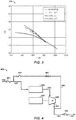
- FIG. 3 is a compressor performance map 300 plotting compressor operation for an injection of various LVFs, i.e., 1% LVF, 2.8% LVF, and 3.8% LVF, at a given speed (8,000 RPM).
- the Y-axis is the PR and the X-axis is the air flow in ACFM.
- increasing the LVF tends to raise the PR at lower flows and has a negligible or lessening effect on the PR at higher flow rates.
- raising the LVF by injecting liquid translates the operating curves in a clockwise orientation about a known point.
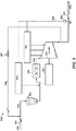
- FIG. 4 is a schematic diagram of a compression system 400.
- Fluid for example fluid from a well head or separator, is directed to the apparatus by a conduit 450, check valve 451 , and conduit 452 .
- the mixture of liquid and gas enters a fluid treatment device 455.
- the fluid treatment device 455 may be a slug suppressor or a known atomizing device, such as one or more atomizing nozzles or flow mixers, to include a static flow mixer, a dynamic flow mixer, or a combination thereof.
- the fluid treatment device 455 may also be a combination of these elements.
- Suitable atomizers may generate droplets having an average droplet size on the order of about 1,000 ⁇ m to about 1,500 ⁇ m, about 1,000 ⁇ m to about 2,000 ⁇ m, about 2,000 ⁇ m to about 3,000 ⁇ m, or larger, while other suitable atomizers, e.g., gas-assisted atomizers, may generate droplets having an average droplet size at least an order of magnitude less than the large droplets (e.g., from about 50 ⁇ m to about 100 ⁇ m, about 100 ⁇ m to about 200 ⁇ m, about 50 ⁇ m to about 200 ⁇ m etc.).
- the mixture leaving the fluid treatment device 455 flows through conduit 456 to compressor 458 driven by a driver 457, e.g., a motor, a turbine, a variable frequency drive (VFD), etc.
- a multi-phase flow meter (MPFM) device (not pictured) is disposed in the conduit 456 to accomplish liquid injection.
- this MPFM is disposed close to the compressor suction nozzle to minimize the likelihood of atomized droplets coalescing in the inlet nozzle and/or compressor volute.
- Such embodiments may utilize the MPFM output to control the ratio of the various streams to obtain the required amount of liquid to obtain the desired operating characteristic, e.g., power, temperature, pressure, erosion characteristics, etc.
- the MPFM may be configured to receive a plurality of inlet sources or a plurality of MPFMs may be individually employed for each of the inlet sources.
- Compressed fluid leaves compressor 458 through conduit 460 and 461 to check valve 462 and to a distribution conduit 463 which delivers the compressed fluid to a desired location.
- a recycle line for the mixture from compressor 458 is provided at 466 that includes a recycle valve 467 , and check valve 469 .
- the distribution conduit 463 may include additional branches, after coolers, moisture separators or other devices for separating/treating the liquid from the gas and passing a single phase stream downstream out of the compression system 400 .
- the compressor 458 may be any suitable centrifugal compressor, e.g., a multi-stage centrifugal compressor, within the scope of this disclosure.
- FIG. 5 is a schematic diagram of an exemplary compression system 500 in accordance with this disclosure.
- the components of FIG. 5 are substantially the same as the corresponding components of FIG. 4 except as otherwise noted.
- the compression system 500 includes an optional suction scrubber 502 .
- the fluid treatment device 455 is a flow mixer and/or atomizer, e.g., an atomizer comprising one or more atomizing nozzles or a flow mixer device comprising two or more counter swirling vanes or counter rotating vortices.
- the compression system 500 depicts a feedback loop 504 having a controller 506.
- the controller 506 may monitor discharge pressure and control the injectant fed back to the compression system 500 via the feedback loop 504 .
- the feedback loop 504 is depicted in dashed lines to illustrate the optional configurations alternately or cumulatively available in some combinations and permutations contemplated herein.
- injectant may be metered and/or injected internally to the compressor 458 at any one or more of the illustrated locations, e.g., the compressor inlet and/or a compressor interstage passage.
- injectant may be metered and/or injected upstream of the fluid treatment device 455.
- the injection location 508 and injection location 510 may have the same or different liquid supply, and in various embodiments may each have one or more different liquid supplies.
- the injection location 508 and the injection location 510 may utilize one or a plurality of liquid injection ports to pass liquid to the compression system 500.
- one or more liquid injection ports may be disposed upstream of a fluid treatment device 455.
- one or more liquid injection ports may be disposed on the compressor 458 , e.g., at the compressor inlet and/or a compressor interstage passage.
- each port may be separately controlled or controlled as part of a bank of liquid injection ports with respect to the quantity of liquid passed therethrough.
- one or more liquid injection ports may be configured to pass a different liquid than another liquid injection port.
- FIG. 6 is a schematic diagram of another embodiment of a compression system 600 in accordance with this disclosure.
- the components of FIG. 6 are substantially the same as the corresponding components of FIG. 5 except as otherwise noted.
- the compression system 600 further comprises a process inlet 602 for admitting process fluid, e.g., a process gas, and a multiphase flow meter 606.
- process fluid e.g., a process gas
- multiphase flow meter 606 e.g., a process inlet 602 for admitting process fluid, e.g., a process gas
- Other embodiments may utilize multiple process inlets 602, e.g., to accommodate multiple process gases, but only one is shown in FIG. 6 .
- other embodiments may utilize multiple conduits 450 (and/or associated control and/or feedback loops) within the scope of this disclosure, e.g., to accommodate multiple kinds of liquids, but only one is shown in FIG. 6 .
- the multiphase flow meter 606 may generate the set point to control the amount of wet gas entering the compressor 458 via the fluid treatment device 455 .
- a feedback loop 604 is provided for aiding in the control of the amount of wet gas entering the compressor 458, e.g., using the control valve 605.
- a second feedback loop 504 is provided for substantially the same purpose as the feedback loop 504 of FIG. 5 .
- the feedback loop 604 and the feedback loop 504 are depicted in dashed lines to illustrate other optional configurations alternately or cumulatively available in some combinations and permutations contemplated herein.
- the feedback loop 504 couples the conduit 461 to the multiphase flow meter 606 for wet gas recycling.
- alternate embodiments may include one or more additional feedback loops for speed control, discharge throttling, suction throttling, recycle control, inlet guide vane control, etc.
- the PR for the compression systems 400, 500, and 600 is controlled by introducing a liquid injectant into an input stream (e.g., passed via conduit 450 ) to create a multiphase input stream.
- the compression systems 400, 500, and 600 compresses the multiphase input stream with a centrifugal compressor (e.g., the compressor 458 ) to create a multiphase discharge stream (e.g., passed via conduit 461 ).
- the compression systems 400, 500, and 600 measures (e.g., using the multiphase flow meter 606 ) a parameter of the streams (e.g., suction pressure, discharge pressure, suction flow, discharge flow, and/or multiphase composition), wherein the discharge parameter corresponds to a PR for the centrifugal compressor.
- a control system e.g., the controller 506
- increases the pressure ratio by increasing (e.g., by manipulating the control valve 605, etc.) the quantity of liquid introduced into the compression systems 400, 500, and 600.
- the liquid may be atomized for purposes of minimizing erosion, but for purposes of controlling the operating point it may be non-atomized.
Landscapes
- Engineering & Computer Science (AREA)
- Mechanical Engineering (AREA)
- General Engineering & Computer Science (AREA)
- Structures Of Non-Positive Displacement Pumps (AREA)
- Control Of Positive-Displacement Air Blowers (AREA)
Claims (12)
- Verfahren zum Steuern eines Druckverhältnisses für ein Verdichtungssystem, bei dem
eine Menge an Flüssigkeit in einen Eingangsstrom eingebracht wird, um einen mehrphasigen Eingangsstrom zu erzeugen,
der mehrphasige Eingangsstrom mit einem Zentrifugalkompressor (458) komprimiert wird, um einen Austragungsstrom zu erzeugen, ein Parameter des Austragungsstroms gemessen wird, wobei der Austragungsparameter einem Druckverhältnis für den Zentrifugalkompressor entspricht,
das Druckverhältnis verändert wird, indem die Menge an Flüssigkeit, die in den Eingangsstrom eingebracht wird, basierend auf dem Parameter geändert wird, dadurch gekennzeichnet, dass das Verändern des Druckverhältnisses einschließt, dass das Druckverhältnis des Zentrifugalkompressors erhöht wird, indem die Menge an Flüssigkeit, die in den Eingangsstrom eingebracht wird, erhöht wird, wenn der Parameter einen ersten vorbestimmten Punkt überschreitet, so dass das Druckverhältnis oberhalb und/oder auf der linken Seite einer Pumpgrenze liegt, ohne eine Stoßwelle oder pulsierenden Rückfluss durch den Zentrifugalkompressor hindurch zu bewirken, und wenn der Parameter einen zweiten vorbestimmten Punkt übersteigt, das Druckverhältnis abgesenkt wird, indem die Menge an eingebrachter Flüssigkeit abgesenkt wird. - Verfahren nach Anspruch 1, bei dem die Flüssigkeit in einen Eingang des Zentrifugalkompressors eingebracht wird.
- Verfahren nach Anspruch 1 oder Anspruch 2, bei dem des Weiteren ein Einphasenstrom aus dem Verdichtungssystem heraus geführt wird.
- Verfahren nach Anspruch 1 oder einem der Ansprüche 2 bis 3, bei dem das Messen des Parameters Messen von mindestens einem Austragungsdruck und Austragungsfluss umfasst.
- Verfahren nach Anspruch 1 oder einem der Ansprüche 2 bis 4, bei dem die Flüssigkeit zerstäubt wird, bevor sie in den Kompressor eingebracht wird.
- Verfahren nach Anspruch 1 oder einem der Ansprüche 2 bis 5, bei dem die Flüssigkeit mindestens eines von produziertem Wasser, flüssigem Kohlenwasserstoff, Korrosionsschutzmittel, Prozessflüssigkeit, Verdünnungsmittel, flüssiger Chemikalie, Bohrfluid und Fracking-Fluid umfasst.
- Verfahren nach Anspruch 4 oder einem der Ansprüche 2 bis 3 oder der Ansprüche 5 bis 6, bei dem der Parameter eine Menge an Flüssigkeit in dem mehrphasigen Austragungsstrom ist.
- Verfahren nach Anspruch 1 oder einem der Ansprüche 2 bis 7, bei dem des Weiteren die Flüssigkeit mindestens teilweise basierend auf der Dichte der Flüssigkeit ausgewählt wird.
- Kompressorsystem, das folgendes umfasst:einen Einlass, der ausgestaltet ist, um einen Einlassstrom zu führen, der Gas umfasst,eine Fluideinspritzvorrichtung, die zumAnnehmen des Einlassstroms,Einbringen eines Flüssigkeitsstroms, der eine Menge an Flüssigkeit umfasst, in den Einlassstrom undErzeugen eines mehrphasigen Einlassstroms ausgestaltet ist, welcher den flüssigen Strom und den Einlassstrom umfasst, wobei der mehrphasige Einlassstrom des Weiteren zerstäubte Flüssigkeit umfasst,einen Zentrifugalkompressor (458), der ausgestaltet ist, um den mehrphasigen Einlassstrom anzunehmen und zu komprimieren und einen Austragungsstrom zu führen, wobei der Zentrifugalkompressor (458) zum Messen eines Parameters des Austragungsstroms ausgestaltet ist, wobei der Austragungsparameter einem Druckverhältnis für den Zentrifugalkompressor entspricht,einen Antrieb (457), der zum Antreiben des Zentrifugalkompressors ausgestaltet ist,einen Auslass, der zum Führen des Austragungsstroms ausgestaltet ist, undeine Steuerung (506) für das Einspritzen des Flüssigstroms, die ausgestaltet ist, um die Menge an Flüssigkeit anzupassen, die an der Fluideinspritzvorrichtung in den Einlassstrom eingebracht wird,dadurch gekennzeichnet, dass die Steuerung für das Einspritzen des Flüssigkeitsstroms ausgestaltet ist, um das Druckverhältnis des Zentrifugalkompressors zu erhöhen, indem die Menge an Flüssigkeit erhöht wird, die in den Eingangsstrom eingebracht wird, wenn der Parameter einen ersten vorbestimmten Punkt überschreitet, wobei das Erhöhen eine Erhöhung auf das Druckverhältnis oberhalb von und/oder auf der linken Seite einer Pumpgrenze einschließt, ohne eine Stoßwelle oder pulsierenden Rückfluss durch den Zentrifugalkompressor hindurch zu bewirken, und wenn der Parameter einen zweiten vorbestimmten Punkt überschreitet, das Druckverhältnis abzusenken, indem die Menge an eingebrachter Flüssigkeit abgesenkt wird.
- Kompressorsystem nach Anspruch 9, bei dem die Fluideinspritzvorrichtung ausgestaltet ist, um Flüssigkeit in mindestens einen von einem Kompressoreinlass und einer Kompressorzwischenstufenposition einzuspritzen.
- Kompressorsystem nach Anspruch 9 oder Anspruch 10, das des Weiteren einen Durchlaufmischer umfasst, wobei die Fluideinspritzvorrichtung ausgestaltet ist, um Flüssigkeit stromaufwärts des Durchlaufmischers, in den Durchlaufmischer oder in beides einzuspritzen.
- Kompressorsystem nach Anspruch 11, das des Weiteren eine Konditionierungsvorrichtung für den Austragungsstrom umfasst, die ausgestaltet ist, um mitgerissene Flüssigkeit aus dem Austragungsstrom zu entfernen.
Applications Claiming Priority (2)
| Application Number | Priority Date | Filing Date | Title |
|---|---|---|---|
| US201562138748P | 2015-03-26 | 2015-03-26 | |
| PCT/US2016/017701 WO2016153626A1 (en) | 2015-03-26 | 2016-02-12 | Method of controlling a compressor system and compressor system |
Publications (2)
| Publication Number | Publication Date |
|---|---|
| EP3274590A1 EP3274590A1 (de) | 2018-01-31 |
| EP3274590B1 true EP3274590B1 (de) | 2020-12-30 |
Family
ID=55456915
Family Applications (1)
| Application Number | Title | Priority Date | Filing Date |
|---|---|---|---|
| EP16708269.2A Active EP3274590B1 (de) | 2015-03-26 | 2016-02-12 | Verfahren zur regelung einer verdichtersanlage und verdichtersanlage |
Country Status (7)
| Country | Link |
|---|---|
| US (2) | US10215184B2 (de) |
| EP (1) | EP3274590B1 (de) |
| JP (1) | JP2018509559A (de) |
| AU (2) | AU2016236054B2 (de) |
| CA (1) | CA2980893C (de) |
| SG (1) | SG11201705462RA (de) |
| WO (1) | WO2016153626A1 (de) |
Citations (1)
| Publication number | Priority date | Publication date | Assignee | Title |
|---|---|---|---|---|
| US20050081529A1 (en) * | 2001-12-06 | 2005-04-21 | Giacomo Bolis | Method and apparatus for achieving power augmentation in gas turbines using wet compression |
Family Cites Families (29)
| Publication number | Priority date | Publication date | Assignee | Title |
|---|---|---|---|---|
| US1385318A (en) | 1920-03-06 | 1921-07-19 | Jens William Egidius Elling | Wet centrifugal compressor |
| US2280845A (en) | 1938-01-29 | 1942-04-28 | Humphrey F Parker | Air compressor system |
| US2786626A (en) | 1952-08-07 | 1957-03-26 | Gulf Oil Corp | Process for the compression of gases |
| US4571151A (en) * | 1983-08-26 | 1986-02-18 | General Electric Company | Liquid injection control in multi-stage compressor |
| US4918931A (en) | 1989-09-05 | 1990-04-24 | Mydax Corporation | Compressor slugging prevention method for a refrigeration system |
| FR2774137B1 (fr) | 1998-01-28 | 2000-02-18 | Inst Francais Du Petrole | Dispositif de compression de gaz humide comportant un etage de compression/separation integrees |
| NL1011383C2 (nl) * | 1998-06-24 | 1999-12-27 | Kema Nv | Inrichting voor het comprimeren van een gasvormig medium en systemen die een dergelijke inrichting omvatten. |
| JP2000097197A (ja) | 1998-09-18 | 2000-04-04 | Hitachi Ltd | 遠心圧縮機水噴射システム |
| US6268074B1 (en) * | 1999-04-05 | 2001-07-31 | General Motors Corporation | Water injected fuel cell system compressor |
| EP1242745A1 (de) | 1999-12-31 | 2002-09-25 | Shell Internationale Researchmaatschappij B.V. | Verfahren und anlage zur optimierung der leistung eines rotodynamischen boosters für eine mehrphasige strömung |
| US6398518B1 (en) * | 2000-03-29 | 2002-06-04 | Watson Cogeneration Company | Method and apparatus for increasing the efficiency of a multi-stage compressor |
| US6463740B1 (en) * | 2000-08-10 | 2002-10-15 | Phillips Petroleum Company | Compressor starting torque converter |
| GB2369935B (en) * | 2000-11-30 | 2005-07-20 | Richard Julius Gozdawa | Gas turbomachinery generator |
| GB0124614D0 (en) | 2001-10-12 | 2001-12-05 | Alpha Thames Ltd | Multiphase fluid conveyance system |
| US6669088B2 (en) * | 2001-11-09 | 2003-12-30 | William J. Veeneman | Multi-merchant gift registry |
| US6826926B2 (en) | 2002-01-07 | 2004-12-07 | Carrier Corporation | Liquid injection for reduced discharge pressure pulsation in compressors |
| AU2003224986A1 (en) * | 2002-04-15 | 2003-11-03 | Mee Industries, Inc. | Water injection for gas turbine inlet air |
| AU2003257385A1 (en) | 2002-07-14 | 2004-02-09 | Rerum Cognitio Gesellschaft Fur Marktintegration Deutscher Innovation Und Forschungsprodukte Mbh | Method for compressing the working fluid during a water/steam combination process |
| EP1896708A1 (de) * | 2005-06-27 | 2008-03-12 | Alstom Technology Ltd | Verfahren zur erhöhung der aerodynamischen stabilität einer arbeitsfluidströmung eines verdichters |
| FR2899288B1 (fr) | 2006-03-30 | 2008-06-13 | Total Sa | Procede et dispositif pour la compression d'un fluide multiphasique |
| US7712301B1 (en) * | 2006-09-11 | 2010-05-11 | Gas Turbine Efficiency Sweden Ab | System and method for augmenting turbine power output |
| US20120224980A1 (en) | 2009-11-25 | 2012-09-06 | Uptigrove Stanley O | Centrifugal wet gas compression or expansion with a slug suppressor and/or atomizer |
| CN103403481B (zh) * | 2010-07-19 | 2017-02-22 | 英国备选能源国际有限公司 | 气体混合物的分离 |
| US9267504B2 (en) * | 2010-08-30 | 2016-02-23 | Hicor Technologies, Inc. | Compressor with liquid injection cooling |
| JP5480792B2 (ja) * | 2010-12-09 | 2014-04-23 | 株式会社日立製作所 | ガスタービンシステム及びガスタービンの加湿制御方法 |
| CN202520580U (zh) * | 2012-04-17 | 2012-11-07 | 溧阳德维透平机械有限公司 | 离心式压缩机 |
| GB201211937D0 (en) | 2012-07-03 | 2012-08-15 | Caltec Ltd | A system to boost the pressure of multiphase well fluids and handle slugs |
| NO337108B1 (no) | 2012-08-14 | 2016-01-25 | Aker Subsea As | Flerfase trykkforsterkningspumpe |
| US10794401B2 (en) * | 2017-03-28 | 2020-10-06 | Uop Llc | Reactor loop fouling monitor for rotating equipment in a petrochemical plant or refinery |
-
2016
- 2016-02-12 JP JP2017549637A patent/JP2018509559A/ja active Pending
- 2016-02-12 SG SG11201705462RA patent/SG11201705462RA/en unknown
- 2016-02-12 US US15/042,528 patent/US10215184B2/en active Active
- 2016-02-12 WO PCT/US2016/017701 patent/WO2016153626A1/en not_active Ceased
- 2016-02-12 EP EP16708269.2A patent/EP3274590B1/de active Active
- 2016-02-12 AU AU2016236054A patent/AU2016236054B2/en active Active
- 2016-02-12 CA CA2980893A patent/CA2980893C/en active Active
-
2018
- 2018-11-30 AU AU2018271401A patent/AU2018271401B2/en active Active
-
2019
- 2019-01-11 US US16/245,526 patent/US10989212B2/en active Active
Patent Citations (1)
| Publication number | Priority date | Publication date | Assignee | Title |
|---|---|---|---|---|
| US20050081529A1 (en) * | 2001-12-06 | 2005-04-21 | Giacomo Bolis | Method and apparatus for achieving power augmentation in gas turbines using wet compression |
Also Published As
| Publication number | Publication date |
|---|---|
| AU2016236054B2 (en) | 2018-11-15 |
| US20160281724A1 (en) | 2016-09-29 |
| CA2980893C (en) | 2019-09-24 |
| US10989212B2 (en) | 2021-04-27 |
| AU2018271401A1 (en) | 2018-12-20 |
| US10215184B2 (en) | 2019-02-26 |
| US20190145419A1 (en) | 2019-05-16 |
| CA2980893A1 (en) | 2016-09-29 |
| WO2016153626A1 (en) | 2016-09-29 |
| JP2018509559A (ja) | 2018-04-05 |
| EP3274590A1 (de) | 2018-01-31 |
| SG11201705462RA (en) | 2017-10-30 |
| AU2016236054A1 (en) | 2017-07-27 |
| AU2018271401B2 (en) | 2019-07-11 |
Similar Documents
| Publication | Publication Date | Title |
|---|---|---|
| AU2010325127B2 (en) | Centrifugal wet gas compression or expansion with a slug suppressor and/or atomizer | |
| EP3274593B1 (de) | Nassgaskompression | |
| EP1198673A1 (de) | Vorrichtung und verfahren für die pumpe einer multi-phasen strömung | |
| US20160138595A1 (en) | Subsea fluid processing system with intermediate re-circulation | |
| CN102575678A (zh) | 用于利用离心泵输送流体的方法 | |
| US10989212B2 (en) | Controlling a wet gas compression system | |
| US20110110796A1 (en) | Water jet type pump and method for operation thereof | |
| CN1890009A (zh) | 向烃类储层中注水的气/液分离器 | |
| Maddocks | Capacity Control Considerations for Acid Gas Injection Systems | |
| Gülich | Influence of the medium on performance | |
| Bakken et al. | Wet gas compressor operation and performance | |
| Bakken et al. | An Experimental Investigation on Hysteresis in a Wet Gas Compressor | |
| Bakken et al. | Volute Flow Influence on Wet Gas Compressor Performance |
Legal Events
| Date | Code | Title | Description |
|---|---|---|---|
| STAA | Information on the status of an ep patent application or granted ep patent |
Free format text: STATUS: THE INTERNATIONAL PUBLICATION HAS BEEN MADE |
|
| PUAI | Public reference made under article 153(3) epc to a published international application that has entered the european phase |
Free format text: ORIGINAL CODE: 0009012 |
|
| STAA | Information on the status of an ep patent application or granted ep patent |
Free format text: STATUS: REQUEST FOR EXAMINATION WAS MADE |
|
| 17P | Request for examination filed |
Effective date: 20171012 |
|
| AK | Designated contracting states |
Kind code of ref document: A1 Designated state(s): AL AT BE BG CH CY CZ DE DK EE ES FI FR GB GR HR HU IE IS IT LI LT LU LV MC MK MT NL NO PL PT RO RS SE SI SK SM TR |
|
| AX | Request for extension of the european patent |
Extension state: BA ME |
|
| DAV | Request for validation of the european patent (deleted) | ||
| DAX | Request for extension of the european patent (deleted) | ||
| GRAP | Despatch of communication of intention to grant a patent |
Free format text: ORIGINAL CODE: EPIDOSNIGR1 |
|
| STAA | Information on the status of an ep patent application or granted ep patent |
Free format text: STATUS: GRANT OF PATENT IS INTENDED |
|
| INTG | Intention to grant announced |
Effective date: 20200804 |
|
| GRAS | Grant fee paid |
Free format text: ORIGINAL CODE: EPIDOSNIGR3 |
|
| GRAA | (expected) grant |
Free format text: ORIGINAL CODE: 0009210 |
|
| STAA | Information on the status of an ep patent application or granted ep patent |
Free format text: STATUS: THE PATENT HAS BEEN GRANTED |
|
| AK | Designated contracting states |
Kind code of ref document: B1 Designated state(s): AL AT BE BG CH CY CZ DE DK EE ES FI FR GB GR HR HU IE IS IT LI LT LU LV MC MK MT NL NO PL PT RO RS SE SI SK SM TR |
|
| REG | Reference to a national code |
Ref country code: GB Ref legal event code: FG4D |
|
| RAP2 | Party data changed (patent owner data changed or rights of a patent transferred) |
Owner name: EXXONMOBIL UPSTREAM RESEARCH COMPANY |
|
| REG | Reference to a national code |
Ref country code: DE Ref legal event code: R096 Ref document number: 602016050548 Country of ref document: DE |
|
| REG | Reference to a national code |
Ref country code: AT Ref legal event code: REF Ref document number: 1350206 Country of ref document: AT Kind code of ref document: T Effective date: 20210115 |
|
| REG | Reference to a national code |
Ref country code: IE Ref legal event code: FG4D |
|
| PG25 | Lapsed in a contracting state [announced via postgrant information from national office to epo] |
Ref country code: RS Free format text: LAPSE BECAUSE OF FAILURE TO SUBMIT A TRANSLATION OF THE DESCRIPTION OR TO PAY THE FEE WITHIN THE PRESCRIBED TIME-LIMIT Effective date: 20201230 Ref country code: NO Free format text: LAPSE BECAUSE OF FAILURE TO SUBMIT A TRANSLATION OF THE DESCRIPTION OR TO PAY THE FEE WITHIN THE PRESCRIBED TIME-LIMIT Effective date: 20210330 Ref country code: FI Free format text: LAPSE BECAUSE OF FAILURE TO SUBMIT A TRANSLATION OF THE DESCRIPTION OR TO PAY THE FEE WITHIN THE PRESCRIBED TIME-LIMIT Effective date: 20201230 Ref country code: GR Free format text: LAPSE BECAUSE OF FAILURE TO SUBMIT A TRANSLATION OF THE DESCRIPTION OR TO PAY THE FEE WITHIN THE PRESCRIBED TIME-LIMIT Effective date: 20210331 |
|
| REG | Reference to a national code |
Ref country code: AT Ref legal event code: MK05 Ref document number: 1350206 Country of ref document: AT Kind code of ref document: T Effective date: 20201230 |
|
| PG25 | Lapsed in a contracting state [announced via postgrant information from national office to epo] |
Ref country code: BG Free format text: LAPSE BECAUSE OF FAILURE TO SUBMIT A TRANSLATION OF THE DESCRIPTION OR TO PAY THE FEE WITHIN THE PRESCRIBED TIME-LIMIT Effective date: 20210330 Ref country code: LV Free format text: LAPSE BECAUSE OF FAILURE TO SUBMIT A TRANSLATION OF THE DESCRIPTION OR TO PAY THE FEE WITHIN THE PRESCRIBED TIME-LIMIT Effective date: 20201230 Ref country code: SE Free format text: LAPSE BECAUSE OF FAILURE TO SUBMIT A TRANSLATION OF THE DESCRIPTION OR TO PAY THE FEE WITHIN THE PRESCRIBED TIME-LIMIT Effective date: 20201230 |
|
| REG | Reference to a national code |
Ref country code: NL Ref legal event code: MP Effective date: 20201230 |
|
| PG25 | Lapsed in a contracting state [announced via postgrant information from national office to epo] |
Ref country code: HR Free format text: LAPSE BECAUSE OF FAILURE TO SUBMIT A TRANSLATION OF THE DESCRIPTION OR TO PAY THE FEE WITHIN THE PRESCRIBED TIME-LIMIT Effective date: 20201230 |
|
| REG | Reference to a national code |
Ref country code: LT Ref legal event code: MG9D |
|
| PG25 | Lapsed in a contracting state [announced via postgrant information from national office to epo] |
Ref country code: RO Free format text: LAPSE BECAUSE OF FAILURE TO SUBMIT A TRANSLATION OF THE DESCRIPTION OR TO PAY THE FEE WITHIN THE PRESCRIBED TIME-LIMIT Effective date: 20201230 Ref country code: PT Free format text: LAPSE BECAUSE OF FAILURE TO SUBMIT A TRANSLATION OF THE DESCRIPTION OR TO PAY THE FEE WITHIN THE PRESCRIBED TIME-LIMIT Effective date: 20210430 Ref country code: SK Free format text: LAPSE BECAUSE OF FAILURE TO SUBMIT A TRANSLATION OF THE DESCRIPTION OR TO PAY THE FEE WITHIN THE PRESCRIBED TIME-LIMIT Effective date: 20201230 Ref country code: EE Free format text: LAPSE BECAUSE OF FAILURE TO SUBMIT A TRANSLATION OF THE DESCRIPTION OR TO PAY THE FEE WITHIN THE PRESCRIBED TIME-LIMIT Effective date: 20201230 Ref country code: LT Free format text: LAPSE BECAUSE OF FAILURE TO SUBMIT A TRANSLATION OF THE DESCRIPTION OR TO PAY THE FEE WITHIN THE PRESCRIBED TIME-LIMIT Effective date: 20201230 |
|
| PG25 | Lapsed in a contracting state [announced via postgrant information from national office to epo] |
Ref country code: AT Free format text: LAPSE BECAUSE OF FAILURE TO SUBMIT A TRANSLATION OF THE DESCRIPTION OR TO PAY THE FEE WITHIN THE PRESCRIBED TIME-LIMIT Effective date: 20201230 Ref country code: PL Free format text: LAPSE BECAUSE OF FAILURE TO SUBMIT A TRANSLATION OF THE DESCRIPTION OR TO PAY THE FEE WITHIN THE PRESCRIBED TIME-LIMIT Effective date: 20201230 |
|
| PG25 | Lapsed in a contracting state [announced via postgrant information from national office to epo] |
Ref country code: MC Free format text: LAPSE BECAUSE OF FAILURE TO SUBMIT A TRANSLATION OF THE DESCRIPTION OR TO PAY THE FEE WITHIN THE PRESCRIBED TIME-LIMIT Effective date: 20201230 Ref country code: IS Free format text: LAPSE BECAUSE OF FAILURE TO SUBMIT A TRANSLATION OF THE DESCRIPTION OR TO PAY THE FEE WITHIN THE PRESCRIBED TIME-LIMIT Effective date: 20210430 |
|
| REG | Reference to a national code |
Ref country code: DE Ref legal event code: R097 Ref document number: 602016050548 Country of ref document: DE |
|
| REG | Reference to a national code |
Ref country code: BE Ref legal event code: MM Effective date: 20210228 |
|
| PG25 | Lapsed in a contracting state [announced via postgrant information from national office to epo] |
Ref country code: CZ Free format text: LAPSE BECAUSE OF FAILURE TO SUBMIT A TRANSLATION OF THE DESCRIPTION OR TO PAY THE FEE WITHIN THE PRESCRIBED TIME-LIMIT Effective date: 20201230 Ref country code: LU Free format text: LAPSE BECAUSE OF NON-PAYMENT OF DUE FEES Effective date: 20210212 Ref country code: LI Free format text: LAPSE BECAUSE OF NON-PAYMENT OF DUE FEES Effective date: 20210228 Ref country code: AL Free format text: LAPSE BECAUSE OF FAILURE TO SUBMIT A TRANSLATION OF THE DESCRIPTION OR TO PAY THE FEE WITHIN THE PRESCRIBED TIME-LIMIT Effective date: 20201230 Ref country code: CH Free format text: LAPSE BECAUSE OF NON-PAYMENT OF DUE FEES Effective date: 20210228 |
|
| PLBE | No opposition filed within time limit |
Free format text: ORIGINAL CODE: 0009261 |
|
| STAA | Information on the status of an ep patent application or granted ep patent |
Free format text: STATUS: NO OPPOSITION FILED WITHIN TIME LIMIT |
|
| GBPC | Gb: european patent ceased through non-payment of renewal fee |
Effective date: 20210330 |
|
| PG25 | Lapsed in a contracting state [announced via postgrant information from national office to epo] |
Ref country code: DK Free format text: LAPSE BECAUSE OF FAILURE TO SUBMIT A TRANSLATION OF THE DESCRIPTION OR TO PAY THE FEE WITHIN THE PRESCRIBED TIME-LIMIT Effective date: 20201230 |
|
| 26N | No opposition filed |
Effective date: 20211001 |
|
| PG25 | Lapsed in a contracting state [announced via postgrant information from national office to epo] |
Ref country code: ES Free format text: LAPSE BECAUSE OF FAILURE TO SUBMIT A TRANSLATION OF THE DESCRIPTION OR TO PAY THE FEE WITHIN THE PRESCRIBED TIME-LIMIT Effective date: 20201230 Ref country code: GB Free format text: LAPSE BECAUSE OF NON-PAYMENT OF DUE FEES Effective date: 20210330 Ref country code: IE Free format text: LAPSE BECAUSE OF NON-PAYMENT OF DUE FEES Effective date: 20210212 Ref country code: FR Free format text: LAPSE BECAUSE OF NON-PAYMENT OF DUE FEES Effective date: 20210228 |
|
| PG25 | Lapsed in a contracting state [announced via postgrant information from national office to epo] |
Ref country code: SI Free format text: LAPSE BECAUSE OF FAILURE TO SUBMIT A TRANSLATION OF THE DESCRIPTION OR TO PAY THE FEE WITHIN THE PRESCRIBED TIME-LIMIT Effective date: 20201230 |
|
| PG25 | Lapsed in a contracting state [announced via postgrant information from national office to epo] |
Ref country code: IS Free format text: LAPSE BECAUSE OF FAILURE TO SUBMIT A TRANSLATION OF THE DESCRIPTION OR TO PAY THE FEE WITHIN THE PRESCRIBED TIME-LIMIT Effective date: 20210430 |
|
| PG25 | Lapsed in a contracting state [announced via postgrant information from national office to epo] |
Ref country code: BE Free format text: LAPSE BECAUSE OF NON-PAYMENT OF DUE FEES Effective date: 20210228 |
|
| P01 | Opt-out of the competence of the unified patent court (upc) registered |
Effective date: 20230518 |
|
| PG25 | Lapsed in a contracting state [announced via postgrant information from national office to epo] |
Ref country code: NL Free format text: LAPSE BECAUSE OF NON-PAYMENT OF DUE FEES Effective date: 20201230 Ref country code: CY Free format text: LAPSE BECAUSE OF FAILURE TO SUBMIT A TRANSLATION OF THE DESCRIPTION OR TO PAY THE FEE WITHIN THE PRESCRIBED TIME-LIMIT Effective date: 20201230 |
|
| PG25 | Lapsed in a contracting state [announced via postgrant information from national office to epo] |
Ref country code: SM Free format text: LAPSE BECAUSE OF FAILURE TO SUBMIT A TRANSLATION OF THE DESCRIPTION OR TO PAY THE FEE WITHIN THE PRESCRIBED TIME-LIMIT Effective date: 20201230 Ref country code: HU Free format text: LAPSE BECAUSE OF FAILURE TO SUBMIT A TRANSLATION OF THE DESCRIPTION OR TO PAY THE FEE WITHIN THE PRESCRIBED TIME-LIMIT; INVALID AB INITIO Effective date: 20160212 |
|
| PG25 | Lapsed in a contracting state [announced via postgrant information from national office to epo] |
Ref country code: MK Free format text: LAPSE BECAUSE OF FAILURE TO SUBMIT A TRANSLATION OF THE DESCRIPTION OR TO PAY THE FEE WITHIN THE PRESCRIBED TIME-LIMIT Effective date: 20201230 |
|
| PG25 | Lapsed in a contracting state [announced via postgrant information from national office to epo] |
Ref country code: TR Free format text: LAPSE BECAUSE OF FAILURE TO SUBMIT A TRANSLATION OF THE DESCRIPTION OR TO PAY THE FEE WITHIN THE PRESCRIBED TIME-LIMIT Effective date: 20201230 |
|
| PG25 | Lapsed in a contracting state [announced via postgrant information from national office to epo] |
Ref country code: MT Free format text: LAPSE BECAUSE OF FAILURE TO SUBMIT A TRANSLATION OF THE DESCRIPTION OR TO PAY THE FEE WITHIN THE PRESCRIBED TIME-LIMIT Effective date: 20201230 |
|
| PGFP | Annual fee paid to national office [announced via postgrant information from national office to epo] |
Ref country code: DE Payment date: 20260220 Year of fee payment: 11 |
|
| PGFP | Annual fee paid to national office [announced via postgrant information from national office to epo] |
Ref country code: IT Payment date: 20260220 Year of fee payment: 11 |