EP3274652B1 - Streifenprojektionsverfahren, streifenprojektionsvorrichtung und computerprogrammprodukt - Google Patents
Streifenprojektionsverfahren, streifenprojektionsvorrichtung und computerprogrammprodukt Download PDFInfo
- Publication number
- EP3274652B1 EP3274652B1 EP16727406.7A EP16727406A EP3274652B1 EP 3274652 B1 EP3274652 B1 EP 3274652B1 EP 16727406 A EP16727406 A EP 16727406A EP 3274652 B1 EP3274652 B1 EP 3274652B1
- Authority
- EP
- European Patent Office
- Prior art keywords
- fringe
- patterns
- pattern
- code
- phase
- Prior art date
- Legal status (The legal status is an assumption and is not a legal conclusion. Google has not performed a legal analysis and makes no representation as to the accuracy of the status listed.)
- Active
Links
Images


Classifications
-
- G—PHYSICS
- G01—MEASURING; TESTING
- G01B—MEASURING LENGTH, THICKNESS OR SIMILAR LINEAR DIMENSIONS; MEASURING ANGLES; MEASURING AREAS; MEASURING IRREGULARITIES OF SURFACES OR CONTOURS
- G01B11/00—Measuring arrangements characterised by the use of optical techniques
- G01B11/24—Measuring arrangements characterised by the use of optical techniques for measuring contours or curvatures
- G01B11/25—Measuring arrangements characterised by the use of optical techniques for measuring contours or curvatures by projecting a pattern, e.g. one or more lines, moiré fringes on the object
- G01B11/2518—Projection by scanning of the object
- G01B11/2527—Projection by scanning of the object with phase change by in-plane movement of the patern
-
- G—PHYSICS
- G01—MEASURING; TESTING
- G01B—MEASURING LENGTH, THICKNESS OR SIMILAR LINEAR DIMENSIONS; MEASURING ANGLES; MEASURING AREAS; MEASURING IRREGULARITIES OF SURFACES OR CONTOURS
- G01B11/00—Measuring arrangements characterised by the use of optical techniques
- G01B11/24—Measuring arrangements characterised by the use of optical techniques for measuring contours or curvatures
- G01B11/25—Measuring arrangements characterised by the use of optical techniques for measuring contours or curvatures by projecting a pattern, e.g. one or more lines, moiré fringes on the object
- G01B11/254—Projection of a pattern, viewing through a pattern, e.g. moiré
-
- G—PHYSICS
- G06—COMPUTING OR CALCULATING; COUNTING
- G06T—IMAGE DATA PROCESSING OR GENERATION, IN GENERAL
- G06T3/00—Geometric image transformations in the plane of the image
- G06T3/06—Topological mapping of higher dimensional structures onto lower dimensional surfaces
Definitions
- the invention relates to a fringe projection method for determining the topography of a body, comprising the steps of (a) projecting a sequence of sets of patterns onto the surface of a body, each set having at least two patterns, and each pattern having S streaks, (b) each pattern capturing an image of the surface with a projected pattern to form a sequence of images; and (c) calculating the topography from the images.
- the invention in a second aspect, relates to a fringe projection apparatus for determining the topography of a body, comprising: (i) a projector for projecting a sequence of sets of patterns onto the surface of the body, (ii) a camera for capturing an image of the surface with a projected pattern and (iii) a controller connected to the projector and the camera.
- the invention relates to a computer program product.
- a correspondence problem For example, to measure the topography of a body, active triangulation techniques are used.
- a plurality of light patterns are successively projected onto the surface of the body to be measured with a projector, and images of the surface illuminated with the pattern are recorded with a camera, which is usually arranged laterally offset from the projector. All these methods have in common that the visual rays of the camera are geometrically cut with the respectively corresponding illumination beam or the respective corresponding illumination plane of the projector.
- the determination of the correspondence between camera pixels and projector pixels or projection line is called a correspondence problem.
- a disadvantage of such a strip projection method is that reflective, for example shiny, surfaces can only be measured very poorly.
- Such a fringe projection method is particularly unreliable for bodies whose surfaces are shaped in such a way that multiple reflections can occur.
- WANG et al "Novel phase-coding method for absolute phase retrieval," OPTICS LETTERS, Optical Society of America, US, Vol. 37, No. 11, 1 June 2012 describes a projection method in which a codeword is coded in the form of a staircase-shaped phase function.
- CN 102322823 (A ) describes a self-coding three-dimensional measuring method on the basis of phase gradients.
- the known methods have the disadvantage that they are less robust against diffuse and / or blurred multiple reflections.
- the invention is based on the object of proposing an improved fringe projection method.
- each stripe has an intensity profile perpendicular to the stripe longitudinal direction and each intensity pattern is describable by a function having a spatial phase position which depends on the ordinal number of the stripe.
- the invention solves the problem by a generic strip projection device according to claim 7, whose control device is adapted to automatically perform a method according to the invention.
- the invention solves the problem by a computer program product according to claim 8.
- An advantage of the invention is that the ordinate changes the intensity curve from the light intensity, which is recorded with a camera pixel, to the location with high accuracy can, which takes the camera pixel. If reflections occur, the proportion of reflected light in the amplitude is the total intensity varying over the image sequence of the light taken with a given camera pixel, small in comparison to the contribution of that light that is not reflected multiple times. The invention therefore makes it possible to measure even reflective, in particular shiny body.
- the spatial resolution is not limited by the stripe width of the narrowest strip.
- Another advantage is the increased robustness against diffuse or blurred reflections. In such reflections, transmission from one surface to the other results in low pass filtering of the pattern signal. This means that low-frequency patterns are transmitted, but high-frequency patterns are attenuated. As a result, high-frequency patterns cause less interference.
- an additional high-frequency pattern is projected over a conventional fringe projection method based on the Gray code, resulting in the improved ruggedness.
- the topography comprises the three-dimensional coordinates of the surface of the body and the reflection behavior.
- the strip longitudinal direction is understood to be the direction in which the strip runs.
- the strip longitudinal direction is the direction along which the strip can be followed without the intensity changing. In the further description, this direction is considered as the y-direction.
- the intensity profile is understood in particular to mean an image which assigns the light intensity to the position perpendicular to the strip longitudinal direction.
- the position perpendicular to the strip longitudinal direction is the x direction.
- the pattern is understood to mean the entirety of other adjacent stripes.
- phase position is that term in the argument of the function, which describes the intensity course, understood, which does not depend on the coordinate.
- the phase is the whole argument of this function.
- the spatial wavelength is at least as large as the stripe width of the stripes.
- phase position depends on the ordinal number of the stripe, it is understood, in particular, that there exists a function which assigns a phase position to each ordinal number.
- projecting means the emission of light, which takes place in such a way that the topography of the body can be determined from the reflected light. It is possible, but not necessary, to use light-bundling components for projecting. This allows sharp pattern projections on matt surfaces. However, it is also possible, for example, for the sequence of sets of patterns to be projected by means of a screen.
- the function is periodic and the intensity traces of the patterns of a sentence have the same spatial frequency. This facilitates the evaluation.
- phase position depends on a code of the ordinal number of the strip, and in each case only a single digit of a code word of the ordinal number. In this way, the topography can be calculated with comparatively small computational effort. Under the code is not understood the trivial code, which assigns exactly the same number to each number.
- the code has a Hamming distance of 1. This increases the robustness of the fringe projection method. It is particularly favorable if the code is an N-ary Gray code, the code alphabet consisting of N symbols. In this case, the phase position is a function of the gray code of the ordinal number of the strip.
- the Gray code is a binary, ternary, quaternary, quinary, seneral, septenary or octal Gray code.
- phase positions of all K patterns within a sentence preferably differ from one another. It is then possible to conclude clearly from the phase positions on the strip and to calculate therefrom the 3D coordinate of the illuminated point of the object.
- At least two patterns of the same set differ in color. It is then possible to project two, three or more patterns simultaneously on the body and to evaluate the individual colors separately. This significantly reduces the measuring time.
- phase position in the s-th stripe of the k-th pattern in the m-th sentence contains the sum of a first term containing s, but not k, and a second term containing k, but not s or m. In this way, by comparing the recorded images for different patterns and / or different sets at the same point on the body can be clearly concluded on the position of the projector pixel and thus the position of the point of the surface of the body.
- phase of the s-th stripe of the k-th pattern in the m-th set the term g 360 ° Sx / X + k ⁇ + s, m ⁇ contains. Based on this term is the determination of the x-coordinate of the light beam or the light plane from the measured light intensity easily possible.
- p is preferably a 360 ° periodic, in particular a trigonometric function.
- a, b and c are real-valued constants.
- 360 ° / N.
- FIG. 1 shows a strip projection device 10 according to the invention for determining the topography of a body 12, which has a projector 14, a camera 16 and a control device 18.
- the projector 14 is configured to project a sequence of sets of patterns T 1 ' , T 2 ,... On a surface 20 of the body 12.
- the successive patterns are drawn together, a time ray 22 intends to indicate that the individual patterns are temporal be projected one after the other. It should be noted, however, that it is also possible to simultaneously project two or more patterns when the patterns differ in their colors.
- the pattern T i projected onto the surface 20 forms a light-dark pattern on the surface 20.
- the camera 16 captures an image 24 for each pattern. Thus, it captures the image 24.1 for the first pattern T 1 , the image 24.2 for the second pattern T 2 , and the image 24.i for the second pattern T 2 in general.
- Figures 24.1 to 24.8 are shown for one of a possible embodiment of the method according to the invention.
- an imaginary line of sight 28 is constructed for each detection point of the camera 16 and cut with a light plane 30. Based on the coordinates of projector 14 and camera 16 and the angles at which the visual beam 28 and the light plane 30 extend, the coordinates of that point P on the surface 20 are determined, which was hit by the light plane 30 and detected by the visual beam 28. This calculation has been known for a long time.
- the challenge is, out of the sequence of light intensities Q k , m for a given camera pixel to conclude which light plane 30 has hit the point P.
- the present description relates to a fringe projection method in which a sequence of sets of patterns is projected onto the surface 20, which allows a particularly accurate determination of the coordinates of the points of the surface 20.
- the sequence of sets of patterns used in the method according to the invention is particularly suitable for measuring bodies 12 with shiny surfaces.
- FIGS. 1 . 2 and 3 show that the patterns T i each have a constant number of S-stripes.
- FIG. 2 shows a scheme for the sequence of sets of patterns for a strip projection method according to the invention.
- the independent coordinate x is drawn.
- the y-direction perpendicular to the x-direction is referred to as the strip longitudinal direction L.
- the brightness along the strip longitudinal direction L is constant for each strip of a pattern T i in the technical sense. This means that the projected light intensity Q perj can fluctuate, but that these fluctuations are so small that they can be neglected for the evaluation.
- the strips extend in the interval [0, X], that is By definition, the smallest x-value is 0, the largest x-value is X.
- the intensity curves Q proj for the temporally successive patterns T 1 , T 2 ,... are shown below.
- This results in the intensity distribution for the pattern T 1 to Q proj, 1 sin (360 ° Sx / X).
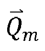
- each set K has patterns which are phase shifted by ⁇ from each other, a K-dimensional intensity vector Q ⁇ m whose components are the intensities of the patterns within a sentence. From the intensity vector Q ⁇ m can be a two-dimensional phase vector ⁇ m are calculated.
- both patterns in the first sentence in the present case are selected so that they merge into one another at the boundaries where two strips adjoin one another.
- the intensity gradients being discontinuous at the boundaries between the four sections.
- the intensity curves are discontinuous at all boundaries between adjacent stripes, but not at those boundaries where discontinuities have already occurred in the previous pattern sets.
- the patterns are projected onto a body, reflected by it and reflected by it Camera taken.
- x is still the x-coordinate of the pattern responsible for the recorded intensity of the camera pixel.
- the value of x is therefore constant but unknown (correspondence problem).
- the s also denotes the ordinal number of the strip and is also constant but unknown.
- the projector strip s and the x-coordinate must be calculated to solve the correspondence problem and triangulate. Also unknown is the amplitude a that arrives in the camera pixel as it is affected by the reflective properties of the body.
- the offset c, or the offset c in the intensities Q k , m of the camera pixel is eliminated by a conventional preprocessing (eg by subtraction with other projected patterns). So S , X , k , ⁇ , m , ⁇ and the coding used by g s, m are known . We are looking for s and then x.
- Prerequisite for a clear solution for ⁇ m is that the rank of H is greater than 1. This is the case if and only if K ⁇ 2 and ⁇ mod 180 ° ⁇ 0.
- the directional angle between the 0th phase vector ⁇ 0 and the mth phase vector ⁇ m corresponds to the phase jump g s , m ⁇ ⁇ : G s . m ⁇ ⁇ ⁇ ⁇ ⁇ ⁇ 0 ⁇ ⁇ m mod 360 °
- the angle function ⁇ a ⁇ . b ⁇ here describes the positive directed angle in the two-dimensional of vector a after vector b in the mathematically positive sense of rotation.
- s can be determined by maximizing.
- the intensity vector ⁇ 0 of the reference signal is rotated so that when correctly s s in the same direction as ⁇ m and in this case the scalar product ⁇ , ⁇ > becomes maximum.
- the x-coordinate of the pattern can be determined using the calculation method known from the phase shift approach. For this it is sufficient to consider the 0th intensity vector.
- the formula x s + ⁇ 1 0 ⁇ ⁇ 0 / 360 ° ⁇ X / S then returns the x-coordinate of the projected pattern perceived by the camera pixel.
- the spatial position of camera 16 and projector 10 which is determined by a calibration measurement, and the imaging properties of camera 16 and projector 10 are then in a known manner by means of triangulation the coordinates determined by P.
- This process is performed automatically by means of the control device 18 for all pixels of the camera 18 and thus the coordinates of points P of the surface 20 are calculated.
- the resulting point cloud describes the topography of the body 12.
Landscapes
- Engineering & Computer Science (AREA)
- Physics & Mathematics (AREA)
- General Physics & Mathematics (AREA)
- Computer Vision & Pattern Recognition (AREA)
- Theoretical Computer Science (AREA)
- Length Measuring Devices By Optical Means (AREA)
Description
- Die Erfindung betrifft ein Streifenprojektionsverfahren zum Bestimmen der Topographie eines Körpers, mit den Schritten (a) Projizieren einer Folge von Sätzen von Mustern auf die Oberfläche eines Körpers, wobei jeder Satz zumindest zwei Muster aufweist und wobei jedes Muster S Streifen hat, (b) für jedes Muster Aufnehmen eines Bildes der Oberfläche mit aufprojiziertem Muster, sodass eine Folge von Bildern entsteht, und (c) berechnen der Topographie aus den Bildern.
- Gemäß einem zweiten Aspekt betrifft die Erfindung eine Streifenprojektionsvorrichtung zum Bestimmen der Topographie eines Körpers, mit (i) einem Projektor zum Projizieren einer Folge von Sätzen von Mustern auf die Oberfläche des Körpers, (ii) einer Kamera zum Aufnehmen eines Bildes der Oberfläche mit aufprojiziertem Muster und (iii) einer Steuervorrichtung, die mit dem Projektor und der Kamera verbunden ist. Gemäß einem dritten Aspekt betrifft die Erfindung ein Computerprogrammprodukt.
- Um die Topographie eines Körpers zu vermessen, werden beispielsweise aktive Triangulationsverfahren verwendet. Dabei werden mit einem Projektor nacheinander mehrere Lichtmuster auf die Oberfläche des zu vermessenden Körpers projiziert und Bilder der mit dem Muster beleuchteten Oberfläche mit einer Kamera aufgenommen, die meist seitlich versetzt zum Projektor angeordnet ist. All diese Verfahren haben gemeinsam, dass die Sehstrahlen der Kamera mit dem jeweils korrespondierenden Beleuchtungsstrahl oder der jeweils korrespondierenden Beleuchtungsebene des Projektors geometrisch geschnitten werden. Die Bestimmung der Korrespondenz zwischen Kamerapixel und Projektorpixel oder Projektionslinie wird Korrespondenzproblem genannt.
- Um das Korrespondenzproblem zu lösen, wurde eine Vielzahl von Projektionsmustern vorgeschlagen. Bekannt ist beispielsweise, den Körper mit einer Folge von Streifenmustern zu bestrahlen, wobei die Streifen in einem zeitlich aufeinander folgendem Muster einem Gray-Code folgen. Vorteilhaft daran ist, dass die Berechnung von Punkten der Oberfläche des Körpers für solche Kamerapixel robuster ist, bei deren Helligkeitswert nicht eindeutig zu entscheiden ist, ob der zugeordnete Punkt auf der Oberfläche des Körpers beleuchtet wurde oder nicht.
- Nachteilig an einem derartigen Streifenprojektionsverfahren ist, dass reflektierende, beispielsweise glänzende, Oberflächen nur sehr schlecht vermessen werden können. Besonders wenig verlässlich ist ein derartiges Streifenprojektionsverfahren für Körper, deren Oberflächen so geformt sind, dass es zu Mehrfachreflexionen kommen kann.
- Auf der
US 2011 008 471 A1 ist ein Verfahren bekannt, bei dem einerseits eine Streifenprojektion auf Basis des Gray-Codes und andererseits eine Projektion mit einer sinusförmigen Intensitätsverteilung verwendet wird. Die Daten, die durch die beiden unterschiedlichen Projektionen gewonnen werden, werden gemeinsam verwendet, um die Gestalt des Probekörpers zu berechnen. Nachteilig an einem derartigen Verfahren ist die vergleichsweise hohe Messzeit, da zwei unterschiedliche Sätze an Streifenmustern projiziert werden müssen. - Aus der
DE 11 2008 002 148 T5 ist ein Verfahren bekannt, was einerseits ein streifenförmiges Lichtmuster, das zum räumlichen Codieren verwendet wird, und ein streifenförmiges Lichtmuster, das für ein Phasenverschiebungsverfahren verwendet wird, einsetzt. Bei diesem Verfahren müssen zwei getrennte Sätze von sich ändernden Mustern auf das Objekt projiziert werden. - Aus der
US 6,930,704 B1 ist ein Verfahren bekannt, bei dem ein Streifenmuster aufprojiziert wird, wobei die Intensitätsverteilung in jedem der Streifen eine Amplitudenmodulation aufweisen kann. Eine Phasencodierung wird nicht verwendet. - In dem Artikel von Sansoni et al "3D Imager for Dimensional Gauging of Industrial Workpieces: State of the Art of the Development of a Robust and Versatile System"; Proceedings of International Conference on Recent Advances in 3-D Digital Imaging and Modeling, 1997, S. 19 - 26, wird ebenfalls das Gray-Code-Projektionsverfahren mit dem Phasen-Verschiebungs-Verfahren kombiniert, wobei auch bei diesem Verfahren jeweils zwei Sätze von Mustern projiziert werden müssen.
- Der gleiche Ansatz findet sich in dem Paper von Sansoni et al: Three-dimensional vision based on a combination of gray-code and phase-shift light projection: analysis and compensation of the systematic errors"; Applied Optics Vol 38, No. 31, 1999, S. 6565 - 6573.
- WANG et al, "Novel phase-coding method for absolute phase retrieval", OPTICS LETTERS, Optical Society of America, US, Bd. 37, Nr. 11, 1. Juni 2012, beschreibt ein Projektionsverfahren, bei dem ein Codewort in Gestalt einer treppenstufenförmigen Phasenfunktion codiert wird.
CN 102322823(A ) beschreibt ein selbstkodierendes dreidimensionales Messverfahren auf der Basis von Phasengradienten. - Die bekannten Verfahren haben den Nachteil, dass sie wenig robust gegenüber diffusen und/oder unscharfen Mehrfachreflexionen sind.
- Der Erfindung liegt die Aufgabe zu Grunde, ein verbessertes Streifenprojektionsverfahren vorzuschlagen.
- Die Erfindung löst das Problem durch ein gattungsgemäßes Streifenprojektionsverfahren gemäß Anspruch 1, bei dem jeder Streifen einen Intensitätsverlauf senkrecht zur Streifen-Längsrichtung aufweist und jeder Intensitätsverlauf durch eine Funktion beschreibbar ist, die eine räumliche Phasenlage hat, die von der Ordinalzahl des Streifens abhängt.
- Gemäß einem zweiten Aspekt löst die Erfindung das Problem durch eine gattungsgemäße Streifenprojektionsvorrichtung gemäß Anspruch 7, deren Steuervorrichtung eingerichtet ist zur automatischen Durchführung eines erfindungsgemäßen Verfahrens.
- Gemäß einem dritten Aspekt löst die Erfindung das Problem durch ein Computerprogrammprodukt gemäß Anspruch 8. Vorteilhaft an der Erfindung ist, dass durch den mit der Ordinalzahl sich verändernden Intensitätsverlauf aus der Lichtintensität, die mit einem Kamerapixel aufgenommen wird, mit hoher Genauigkeit auf den Ort geschlossen werden kann, den das Kamerapixel aufnimmt. Kommt es zu Reflexionen, so ist der Anteil von reflektiertem Licht an der Amplitude, der über die Bildfolge variierenden Gesamtintensität des Lichts, das mit einem vorgegebenen Kamerapixel aufgenommen wird, klein im Vergleich zu dem Beitrag desjenigen Lichts, das nicht mehrfach reflektiert wird. Die Erfindung erlaubt es daher, auch reflektierende, insbesondere glänzende Körper zu vermessen.
- Vorteilhaft ist zudem, dass die räumliche Auflösung nicht durch die Streifenbreite des schmalsten Streifens begrenzt wird.
- Ein weiterer Vorteil ist die erhöhte Robustheit gegenüber diffusen oder unscharfen Reflexionen. Bei solchen Reflexionen kommt es bei der Übertragung von einer Oberfläche zu der anderen zu einer Tiefpassfilterung des Mustersignals. Das heißt niederfrequente Muster werden übertragen, aber hochfrequente Muster abgeschwächt. Dadurch verursachen hochfrequente Muster weniger Störungen. In der Erfindung wird gegenüber einem herkömmlichen Streifenprojektionsverfahren auf Basis des Gray-Codes ein zusätzliches hochfrequentes Muster aufprojiziert, was zu der verbesserten Robustheit führt.
- Im Rahmen der vorliegenden Beschreibung umfasst die Topographie die dreidimensionalen Koordinaten der Oberfläche des Körpers und das Reflexionsverhalten.
- Unter der Streifen-Längsrichtung wird diejenige Richtung verstanden, in die der Streifen verläuft. In anderen Worten ist die Streifen-Längsrichtung diejenige Richtung, entlang der man dem Streifen folgen kann, ohne dass sich die Intensität verändert. In der weiteren Beschreibung wird diese Richtung als y-Richtung betrachtet.
- Unter dem Intensitätsverlauf wird insbesondere eine Abbildung verstanden, die der Position senkrecht zur Streifen-Längsrichtung die Lichtintensität zuordnen. Die Position senkrecht zur Streifen-Längsrichtung ist die x-Richtung.
- Unter dem Muster wird die Gesamtheit von anderen angrenzenden Streifen verstanden.
- Unter der Phasenlage wird derjenige Term im Argument der Funktion, die den Intensitätsverlauf beschreibt, verstanden, der nicht von der Koordinate abhängt. Unter der Phase wird das gesamte Argument dieser Funktion verstanden.
- Es ist vorteilhaft, wenn die räumliche Wellenlänge mindestens so groß ist wie die Streifenbreite der Streifen.
- Unter dem Merkmal, dass die Phasenlage von der Ordinalzahl des Streifens abhängt, wird insbesondere verstanden, dass eine Funktion existiert, die jeder Ordinalzahl eine Phasenlage zuordnet.
- Unter einem Projizieren wird insbesondere das Aussenden von Licht verstanden, das so erfolgt, dass aus dem reflektierten Licht die Topographie des Körpers bestimmt werden kann. Es ist möglich, nicht aber notwendig, dass zum Projizieren lichtbündelnde Bauteile verwendet werden. Das erlaubt scharfe Musterprojektionen auf matten Oberflächen. Es ist aber beispielsweise auch möglich, dass das Projizieren der Folge von Sätzen von Mustern mittels eines Bildschirms erfolgt.
- Die Funktion ist periodisch und die Intensitätsverläufe der Muster eines Satzes haben die gleiche räumliche Frequenz. Das erleichtert die Auswertung.
- Die Phasenlage hängt von einem Code der Ordinalzahl des Streifens ab, und zwar von jeweils nur einer einzigen Stelle eines Codeworts der Ordinalzahl. Auf diese Weise kann die Topographie mit vergleichsweise kleinem Rechenaufwand berechnet werden. Unter dem Code wird nicht der triviale Code verstanden, der jeder Zahl genau die gleiche Zahl zuordnet.
- Vorzugsweise hat der Code einen Hamming-Abstand von 1. Das erhöht die Robustheit des Streifenprojektionsverfahrens. Besonders günstig ist es, wenn der Code ein N-ärer Gray-Code ist, wobei das Code-Alphabet aus N Symbolen besteht. In diesem Fall ist die Phasenlage eine Funktion des Gray-Codes der Ordinalzahl des Streifens. Vorzugsweise ist der Gray-Code ein binärer, ternärer, quaternärer, quinärer, senärer, septenärer oder oktaler Gray-Code.
- Vorzugsweise unterscheiden sich die Phasenlagen aller K-Muster innerhalb eines Satzes voneinander. Es ist dann möglich, aus den Phasenlagen eindeutig auf den Streifen zu schließen und daraus die 3D-Koordinate des beleuchteten Punktes des Objektes zu berechnen.
- Vorzugsweise unterscheiden sich zumindest zwei Muster des gleichen Satzes in ihrer Farbe. Es ist dann möglich, zwei, drei oder mehr Muster gleichzeitig auf den Körper zu projizieren und die einzelnen Farben getrennt voneinander auszuwerten. So wird die Messzeit deutlich verringert. Wenn eine besonders hohe räumliche Auflösung erwünscht ist, ist es jedoch meistens vorteilhaft, ein monochromes bzw. graues Muster auf die Oberfläche des Körpers zu projizieren und die Bilder der Oberfläche mit einer monochromen Kamera aufzunehmen. Diese besitzen in der Regel chipbedingt eine höhere räumliche Auflösung und Lichtempfindlichkeit.
- Günstig ist es, wenn die Phasenlage im s-ten Streifen des k-ten Musters im m-ten Satz die Summe enthält aus einem ersten Term, der s enthält, nicht aber k, und einem zweiten Term, der k enthält, nicht aber s oder m. Auf diese Weise kann durch Vergleich der aufgenommenen Bilder für unterschiedliche Muster und/oder unterschiedliche Sätze bei gleichbleibendem Punkt auf dem Körper eindeutig auf die Position des Projektorpixels und damit auf die Position des Punktes der Oberfläche des Körpers geschlossen werden.
- Besonders günstig ist es, wenn die Phase für den s-ten Streifen des k-ten Musters im m-ten Satz den Term 360°Sx / X+kϕ + gs,mδ enthält. Anhand dieses Terms ist die Bestimmung der x-Koordinate des Lichtstrahls bzw. der Lichtebene aus der gemessenen Lichtintensität leicht möglich.
- Besonders günstig ist es, wenn die Intensität Q am Ort x für den s-ten Streifen des k-ten Musters im m-ten Satz gegeben ist durch:
Qk,s,m(x) = a·p[360°Sx /X + kϕ + gs,m δ]+bx+c. Dabei ist p vorzugsweise eine in 360° periodische, insbesondere eine trigonometrische Funktion. a, b und c sind reellwertige Konstanten. - Günstig ist es, wenn für den Phasenversatzparameter |δ|≤360°(N-1) gilt, wobei N=#A und A={0,1,...,N-1} das Alphabet des Codes ist. Vorzugsweise gilt für den Phasenversatzparameter |δ|=360°/N.
- Gemäß einer bevorzugten Ausführungsform umfasst das Verfahren die Schritte
- (a) Berechnen der Lage einer Lichtebene aus den Lichtintensitäten, die mit einem Pixel der Kamera für die Muster an der gleichen Stelle gemessen werden und
- (b) Berechnen der 3D-Koordinaten dieser Stelle durch Triangulation aus der Lichtebene und dem Sehstrahl, der zu dieser Stelle führt. Diese Schritte werden für mehrere, insbesondere für alle Pixel der Kamera durchgeführt.
- Im Folgenden wird die Erfindung anhand der beigefügten Zeichnungen näher erläutert. Dabei zeigt
- Figur 1
- eine schematische Ansicht einer erfindungsgemäßen Streifenprojektionsvorrichtung zum Durchführen eines erfindungsgemäßen Verfahrens,
- Figur 2
- ein Diagramm zur Erläuterung einer Ausführungsform eines erfindungsgemäßen Verfahrens,
- Figur 3
- eine Folge von Mustern, die gemäß einer Ausführungsform projiziert wurden, und
- Figur 4
- eine exemplarische Folge von Kamerabildern, die bei Projektion der Muster aus
Figur 3 entstehen. -
Figur 1 zeigt eine erfindungsgemäße Streifenprojektionsvorrichtung 10 zum Bestimmen der Topographie eines Körpers 12, die einen Projektor 14, eine Kamera 16 und eine Steuervorrichtung 18 aufweist. Der Projektor 14 ist ausgebildet zum Projizieren einer Folge von Sätzen von Mustern T1', T2,... auf eine Oberfläche 20 des Körpers 12. Die aufeinander folgenden Muster sind gemeinsam eingezeichnet, ein Zeitstrahl 22 soll andeuten, dass die einzelnen Muster zeitlich nacheinander projiziert werden. Es sei angemerkt, dass es allerdings auch möglich ist, zwei oder mehr Muster gleichzeitig zu projizieren, wenn sich die Muster in ihren Farben unterscheiden. - Durch die auf die Oberfläche 20 projizierten Muster Ti bildet sich auf der Oberfläche 20 ein Hell-Dunkel-Muster. Die Kamera 16 nimmt für jedes Muster ein Bild 24 auf. So nimmt sie zum ersten Muster T1 das Bild 24.1 auf, zum zweiten Muster T2 das Bild 24.2, und ganz allgemein zum i-ten Muster das Bild 24.i. In
Figur 3 sind die Bilder 24.1 bis 24.8 für eine für eine mögliche Ausführungsform des erfindungsgemäßen Verfahrens gezeigt. - Zur Berechnung der Topographie des Körpers 12, insbesondere also der dreidimensionalen Koordinaten der Oberfläche 20 in einem vorgegebenen Koordinatensystem, wird für jeden Detektionspunkt der Kamera 16 ein gedachter Sehstrahl 28 konstruiert und mit einer Lichtebene 30 geschnitten. Anhand der Koordinaten von Projektor 14 und Kamera 16 sowie den Winkeln, unter denen der Sehstrahl 28 und der Lichtebene 30 verlaufen, werden die Koordinaten desjenigen Punkts P auf der Oberfläche 20 bestimmt, der von der Lichtebene 30 getroffen und vom Sehstrahl 28 erfasst wurde. Diese Berechnung ist seit langem bekannt. Die Herausforderung ist es, aus der Folge an Lichtintensitäten
Q k,m für ein vorgegebenes Kamerapixel darauf zu schließen, welche Lichtebene 30 auf den Punkt P aufgetroffen ist. - Die vorliegende Beschreibung bezieht sich auf ein Streifenprojektionsverfahren, bei dem eine Folge von Sätzen von Mustern auf die Oberfläche 20 projiziert wird, die eine besonders genaue Bestimmung der Koordinaten der Punkte der Oberfläche 20 erlaubt. Zudem ist die im erfindungsgemäßen Verfahren verwendete Folge von Sätzen von Mustern besonders gut dazu geeignet, Körper 12 mit glänzenden Oberflächen zu vermessen.
- Die
Figuren 1 ,2 und3 zeigen, dass die Muster Ti jeweils eine konstante Anzahl von S-Streifen haben. -
Figur 2 zeigt ein Schema für die Folge von Sätzen von Mustern für ein erfindungsgemäßes Streifenprojektionsverfahren. Ganz oben ist die unabhängige Koordinate x eingezeichnet. Die zur x-Richtung senkrechte y-Richtung wird als Streifen-Längsrichtung L bezeichnet. Die Helligkeit entlang der Streifen-Längsrichtung L ist für jeden Streifen eines Musters Ti im technischen Sinne konstant. Das heißt, dass die projizierte Lichtintensität Qproj zwar schwanken kann, dass diese Schwankungen aber so klein sind, dass sie für die Auswertung vernachlässigt werden können. - In
Figur 2 ist schematisch eine Folge von Sätzen von Mustern Ti für S= 16 Streifen gezeigt. Der Zählindex s der Streifen beginnt mit 0, das heißt, dass die Streifen durchnummeriert sind mit s= 0, s= 1, ..., s= 15. In Koordinaten erstrecken sich die Streifen im Intervall [0, X], das heißt der kleinste x-Wert ist definitionsgemäß 0, der größte x-Wert ist X. - Nach unten sind die Intensitätsverläufe Qproj für die zeitlich aufeinanderfolgenden Muster T1, T2, ...eingezeichnet. Im vorliegendem Fall gilt Qproj=Qm,k,s = sin (360°Sx/X + kϕ + gs,m δ), wobei δ= 360°/N gilt. N ist die Anzahl der Symbole im Alphabet des verwendeten Gray-Codes. Damit ergibt sich die Intensitätsverteilung für das Muster T1 zu Qproj,1= sin (360°Sx/X). Das erste Muster T1 ist Teil des ersten Satzes, also m= 0, und des ersten Musters, daher k= 0.
- Da jeder Satz K Muster besitzt, die zueinander um ϕ phasenverschoben sind, kann ein K-dimensionaler Intensitätsvektor

Ψ m berechnet werden. - Es ist zu erkennen, dass beide Muster im ersten Satz im vorliegenden Fall so gewählt sind, dass sie an den Grenzen, an denen zwei Streifen aneinander angrenzen, stetig ineinander übergehen.
- Im zweiten Satz existieren in
Figur 2 vier voneinander getrennte Abschnitte mit jeweils vier Streifen, wobei die Intensitätsverläufe an den Grenzen zwischen den vier Abschnitten unstetig sind. Im dritten Satz sind die Intensitätsverläufe an allen Grenzen zwischen benachbarten Streifen unstetig, nicht jedoch an denjenigen Grenzen, an denen in den vorherigen Mustersätzen bereits Unstetigkeiten vorgekommen sind. - Auf Basis der beschriebenen Folge von Sätzen von Mustern wird aus den von der Kamera 16 (vgl.
Figur 1 ) aufgenommenen Bildpunkten auf die im Folgenden beschriebene Weise die Topographie des Körpers berechnet. - Beim 0.ten Mustersatz, also m=0, ist die Phasenlage nicht abhängig von der Ordinalzahl s des Streifens. Dies kann dadurch erreicht werden, dass für die 0te Stelle des Gray-Codewortes g(s) von S immer der Wert 0 gewählt wird, also gs,0=0 für alle s ∈ {0,1, ..., s-1}.
- Dies entspricht einer Erweiterung des Gray-Codes um eine zusätzliche 0.te Stelle, das heißt für S=16 Streifen werden 3-stellige Codewörter verwendet, obwohl für die Codierung von 16 Streifen, mit einem 4-ären Gray-Code, 2 Stellen ausreichen würden.
- Der Intensitätsverlauf des k-ten Musters im m-ten Satz sei wie vorher beschrieben Q k,s,m (x) = a · sin(360° · S · x/X + k · ϕ + g s,m · δ) + c mit der Phasenlage

- Die Muster werden auf einen Körper projiziert, von diesem reflektiert und von einer Kamera aufgenommen. Die Intensitäten
Q k,m die bei jeweils einem Kamerapixel ankommen entsprechen
- Dabei bezeichnet x weiterhin die x-Koordinate des Musters, die für die aufgenommene Intensität des Kamerapixels verantwortlich ist. Der Wert von x ist demnach konstant aber unbekannt (Korrespondenzproblem). Das s bezeichnet weiterhin die Ordinalzahl des Streifens und ist ebenfalls konstant aber unbekannt.
- Der Projektorstreifen s und die x-Koordinate müssen berechnet werden, um das Korrespondenzproblem zu lösen und eine Triangulation durchführen zu können. Außerdem unbekannt ist die Amplitude
a , die im Kamerapixel ankommt, da sie von den Reflexionseigenschaften des Körpers beeinflusst wird. - Der Offset c, bzw. der Offset
c in den IntensitätenQ k,m des Kamerapixels wird durch eine übliche Vorverarbeitung (z.B. durch Differenzbildung mit anderen projizierten Mustern) eliminiert. Bekannt sind also S,X,k,ϕ,m,δ sowie die verwendete Codierung von gs,m . Gesucht ist zunächst s und dann x. - Weiterhin sei angenommen, dass der 0. Mustersatz (m=0 bzw. das Referenzsignal) keine Phasenverschiebung enthält, also für alle s ∈ {0, 1, ...,S - 1} gilt g s,0 = 0. Bei Projektion des 0-ten Mustersatzes sind die Intensitäten des Kamerapixels also

- Für die Berechnung von s und x fassen wir zuerst alle in einem Kamerapixel aufgenommenen Intensitäten mit k ∈ {0,1, ..., K - 1} jeweils eines Mustersatzes zu einem Intensitätsvektor
Q m zusammen
- Nach den Additionstheoremen der Trigonometrie gilt:

- (1) ergibt sich

Ψ m . - Im Fall von K = 2 und ϕ = 90° wird H zur Einheitsmatrix und es gilt der einfache Zusammenhang

- Im allgemeinen Fall kann der Phasenvektor
Ψ m mit Hilfe der Pseudoinverse (Moore-Penrose-Inverse) H + berechnet werden:
- Voraussetzung für eine eindeutige Lösung für
Ψ m ist, dass der Rang von H größer ist als 1. Dies ist genau dann der Fall, wenn gilt: K ≥ 2 und ϕ mod 180° ≠ 0. - Für die Berechnung von s gibt es nun zumindest zwei Möglichkeiten.
- Der gerichtete Winkel zwischen dem 0-ten Phasenvektor
Ψ 0 und dem m-ten PhasenvektorΨ m entspricht dem Phasensprung g s,m · δ:
- Die Winkelfunktion

a nach Vektorb im mathematisch positiven Drehsinn. Dieser Winkel kann z.B. mit Hilfe der bekannten atan2-Funktion berechnet werden:
- Für die Berechnung des gesuchten Projektorstreifens s wird nun derjenige Zahlenwert
s ∈ {0,1, ...,S - 1} gewählt, für den die Kongruenzgleichung (2) für alle m ∈
{1, ...,M - 1} erfüllt ist. - Robuster kann s über eine Maximierung bestimmt werden. Hierfür wird der Intensitätsvektor
Ψ 0 des Referenzsignals so gedreht, dass er bei korrekt gewähltem s in die gleiche Richtung wieΨ m zeigt und in diesem Fall das Skalarprodukt 〈·,·〉 maximal wird.
- Nach Berechnung des Projektorstreifens s kann die x-Koordinate des Musters mit vom Phasenshift-Ansatz bekannten Berechnungsverfahren bestimmt werden. Hierfür reicht es aus den 0-ten Intensitätsvektors zu betrachten. Die Formel

- Aus der so berechneten x-Koordinate des Projektors und der Koordinate des Kamerapixels, der räumlichen Lage von Kamera 16 und Projektor 10, welche anhand einer Kalibriermessung bestimmt wird, sowie den Abbildungseigenschaften von Kamera 16 und Projektor 10 werden dann auf bekannte Weise mittels Triangulation die Koordinaten von P bestimmt. Dieses Verfahren wird automatisch mittels der Steuervorrichtung 18 für alle Pixel der Kamera 18 durchgeführt und so die Koordinaten von Punkten P der Oberfläche 20 berechnet. Die entstehende Punktwolke beschreibt die Topographie des Körpers 12.
Bezugszeichenliste 10 Streifenprojektionsvorrichtung k Laufindex der Muster im Satz 12 Körper K Anzahl der Muster pro Satz 14 Projektor L Streifen-Längsrichtung 16 Kamera m Laufindex des Satzes 18 Steuervorrichtung M Anzahl der Sätze 20 Oberfläche N Anzahl der Symbole des Code-Alphabets 22 Zeitstrahl 24 Kamerabild p Funktion 28 Sehstrahl P Punkt auf Oberfläche 30 Lichtebene Q k,merfasste Intensität Qproj projizierte Licht-Intensität β Phasenlage t Zeit δ Phasenversatzparameter ϕ Differenzwinkel S Laufindex der Streifen a reelle Zahl S Anzahl der Streifen b reelle Zahl T Muster c reelle Zahl x Musterkoordinate g Funktion, die einer Zahl ihren Gray-Code zuordnet X Breite der Muster bzw. größt-mögliche Koordinate g s,m m-te Stelle des Graykodes von s y Musterkoordinate parallel zum Streifen
Claims (8)
- Streifenprojektionsverfahren zum Bestimmen der Topographie eines Körpers (12), mit den Schritten:(a) Projizieren einer Folge von Sätzen (m) von Mustern (Ti) auf die Oberfläche (20) des Körpers (12), wobei jeder Satz (m) zumindest zwei Muster (Ti) aufweist und wobei jedes Muster (Ti) S Streifen hat;(b) für jedes Muster (Ti) Aufnehmen eines Bildes (24.i) der Oberfläche (20) mit aufprojiziertem Muster, sodass eine Folge von Aufnahmen entsteht, und(c) Berechnen der Topographie aus den Bildern (24.i),(d) wobei solche Muster (Ti) projiziert werden, bei denen jeder Streifen einen Intensitätsverlauf senkrecht zur Streifen-Längsrichtung (L) aufweist und jeder Intensitätsverlauf durch eine periodische Funktion (Q) beschreibbar ist, die eine räumliche Phasenlage (ß) hat, wobei alle Intensitätsverläufe die gleiche räumliche Frequenz haben, und(e) die Phasenlage (ß) sich in Abhängigkeit von einem Code (g(s)) der Ordinalzahl (s) des Streifens ändert, wobei die Phasenlagen (ß) der Streifen der Muster (Ti) eines jeweiligen Satzes (m) von jeweils nur einer einzigen Codewortstelle des Codes (g(s)) der Ordinalzahl (s) abhängen.
- Streifenprojektionsverfahren nach Anspruch 1, dadurch gekennzeichnet, dass sich die Phasenlagen (ß) für alle k Muster innerhalb eines Satzes voneinander unterscheiden.
- Streifenprojektionsverfahren nach einem der vorstehenden Ansprüche, dadurch gekennzeichnet, dass
die Phasenlage (ß) im s-ten Streifen des k-ten Musters im m-ten Satz die Summe enthält auseinem ersten Term, der s enthält, nicht aber k enthält, undeinem zweiten Term, der k enthält, nicht aber s oder m. - Streifenprojektionsverfahren nach Anspruch 3, dadurch gekennzeichnet, dass die Phase für den s-ten Streifen des k-ten Musters im m-ten Satz den Term
 S die Gesamtzahl an Streifen ist (s = 0,1,...., S-1),x die Koordinate senkrecht zur Streifenlängsrichtung ist,X die obere Intervallgrenze der x-Werte ist (x ∈{0,....,X}),ϕ ein Differenzwinkel ist mit ϕ mod 360° ≠ 0°,gs,m die m-te Stelle des Codes, insbesondere Gray-Codes, g von s ist undδ ein Phasenversatzparameter ist mit δ mod 360° ≠ 0°.
 - Streifenprojektionsverfahren nach Anspruch 4, dadurch gekennzeichnet, dass die Intensität Q am Ort x für den s-ten Streifen des k-ten Musters im m-ten Satz gegeben ist durch:
 wobei p eine in 360°periodische, insbesondere eine trigonometrische, Funktion ist,wobei a eine reellwertige Konstante ist undwobei b eine reellwertige Konstante ist undwobei c eine reellwertige Konstante ist.
 - Streifenprojektionsverfahren nach Anspruch 5, dadurch gekennzeichnet, dass für den Phasenversatzparameter

- Streifenprojektionsvorrichtung zum Bestimmen der Topographie eines Körpers, mit(i) einem Projektor zum Projizieren einer Folge von Sätzen von Mustern auf die Oberfläche (20) eines Körpers (12),(ii) einer Kamera (16) zum Aufnehmen eines Bilds (24) der Oberfläche (20) mit aufprojiziertem Muster und(iii) einer Rechenvorrichtung (18), die mit dem Projektor (14) und der Kamera (16) verbunden ist,
dadurch gekennzeichnet, dass(iv) die Rechenvorrichtung (18) zum automatischen Durchführen eines Verfahrens nach einem der vorstehenden Ansprüche eingerichtet ist. - Computerprogrammprodukt, das auf einem maschinenlesbaren Medium gespeichert ist und beim Ausführen auf einer Rechenvorrichtung (18)(i) Ansteuersignale erzeugt, mittels denen eine Streifenprojektionsvorrichtung (10), die- einen Projektor (14) zum Projizieren einer Folge von Sätzen von Mustern auf die Oberfläche (20) eines Körpers (12) und- eine Kamera (16) zum Aufnehmen eines Bilds (24) der Oberfläche (20) mit aufprojiziertem Muster aufweist,so angesteuert wird, dass eine Folge von Bildern (24.i) entsteht, und(ii) aus der Folge von Bildern (24.i) die Topographie des Körpers (12) berechnet,(iii) wobei jeder Streifen einen Intensitätsverlauf senkrecht zur Streifen-Längsrichtung (L) aufweist,jeder Intensitätsverlauf durch eine periodische Funktion (Q) beschreibbar ist, die eine räumliche Frequenz und eine räumliche Phasenlage (ß) hat, wobei alle Intensitätsverläufe die gleiche räumliche Frequenz haben, und
die Phasenlage (ß) sich in Abhängigkeit von einem Code (g(s)) der Ordinalzahl des Streifens ändert, wobei die Phasenlage (ß) der Streifen der Muster (Ti) eines jeweiligen Satzes (m) von jeweils nur einer einzigen Codewortstelle des Codes (g(s)) der Ordinalzahl (s) abhängen.
Applications Claiming Priority (2)
| Application Number | Priority Date | Filing Date | Title |
|---|---|---|---|
| DE102015109721.4A DE102015109721B3 (de) | 2015-06-17 | 2015-06-17 | Streifenprojektionsverfahren, Streifenprojektionsvorrichtung und Computerprogrammprodukt |
| PCT/EP2016/062100 WO2016202562A1 (de) | 2015-06-17 | 2016-05-30 | Streifenprojetionsverfahren, streifenprojektionsvorrichtung und computerprogrammprodukt |
Publications (2)
| Publication Number | Publication Date |
|---|---|
| EP3274652A1 EP3274652A1 (de) | 2018-01-31 |
| EP3274652B1 true EP3274652B1 (de) | 2019-11-13 |
Family
ID=56108625
Family Applications (1)
| Application Number | Title | Priority Date | Filing Date |
|---|---|---|---|
| EP16727406.7A Active EP3274652B1 (de) | 2015-06-17 | 2016-05-30 | Streifenprojektionsverfahren, streifenprojektionsvorrichtung und computerprogrammprodukt |
Country Status (5)
| Country | Link |
|---|---|
| US (1) | US10801834B2 (de) |
| EP (1) | EP3274652B1 (de) |
| CN (1) | CN107810384B (de) |
| DE (1) | DE102015109721B3 (de) |
| WO (1) | WO2016202562A1 (de) |
Families Citing this family (6)
| Publication number | Priority date | Publication date | Assignee | Title |
|---|---|---|---|---|
| CN109974624B (zh) * | 2019-03-22 | 2020-09-29 | 华中科技大学 | 一种基于多频相移的减少投影图像数量的方法 |
| CN113532325B (zh) * | 2021-06-08 | 2023-05-05 | 深圳市格灵精睿视觉有限公司 | 动态步数解相方法、电子设备及计算机可读存储介质 |
| CN113409367B (zh) * | 2021-07-08 | 2023-08-18 | 西安交通大学 | 条纹投影测量点云逐点加权配准方法、设备和介质 |
| CN115930834B (zh) * | 2022-11-14 | 2025-09-19 | 东南大学 | 一种消除间接照明和随机噪声影响的双频校正方法 |
| CN119309509B (zh) * | 2024-10-10 | 2025-12-05 | 四川大学 | 一种基于四元互补格雷码辅助相位展开的三维测量方法 |
| CN120543769B (zh) * | 2025-07-29 | 2025-10-14 | 武汉工程大学 | 一种互反射环境下的数字光栅投影三维重建方法 |
Family Cites Families (10)
| Publication number | Priority date | Publication date | Assignee | Title |
|---|---|---|---|---|
| JP2000292134A (ja) * | 1999-04-07 | 2000-10-20 | Minolta Co Ltd | 3次元情報入力カメラ |
| CN1149388C (zh) * | 2001-02-23 | 2004-05-12 | 清华大学 | 一种基于移相法的数字投影三维轮廓重构方法 |
| JP4931728B2 (ja) | 2007-08-08 | 2012-05-16 | シーケーディ株式会社 | 三次元計測装置及び基板検査機 |
| WO2009086471A2 (en) | 2007-12-27 | 2009-07-09 | Tyratech, Inc. | Synergistic antiparasitic compositions and screening methods |
| US20110080471A1 (en) * | 2009-10-06 | 2011-04-07 | Iowa State University Research Foundation, Inc. | Hybrid method for 3D shape measurement |
| US20120176478A1 (en) | 2011-01-11 | 2012-07-12 | Sen Wang | Forming range maps using periodic illumination patterns |
| CN102322823B (zh) * | 2011-09-13 | 2013-01-23 | 四川大学 | 基于相位级次自编码的光学三维测量方法 |
| CN102519390B (zh) | 2011-12-21 | 2015-01-07 | 哈尔滨理工大学 | 三编码周期灰度梯形相移结构光三维信息获取方法 |
| CN102607465B (zh) | 2012-03-13 | 2015-01-21 | 西安交通大学 | 一种基于彩色相移条纹二次编码的相位去包裹方法 |
| US9459094B2 (en) * | 2013-09-12 | 2016-10-04 | Hong Kong Applied Science and Technology Research Institute Company Limited | Color-encoded fringe pattern for three-dimensional shape measurement |
-
2015
- 2015-06-17 DE DE102015109721.4A patent/DE102015109721B3/de not_active Expired - Fee Related
-
2016
- 2016-05-30 US US15/569,211 patent/US10801834B2/en active Active
- 2016-05-30 EP EP16727406.7A patent/EP3274652B1/de active Active
- 2016-05-30 WO PCT/EP2016/062100 patent/WO2016202562A1/de not_active Ceased
- 2016-05-30 CN CN201680025255.0A patent/CN107810384B/zh active Active
Non-Patent Citations (1)
| Title |
|---|
| None * |
Also Published As
| Publication number | Publication date |
|---|---|
| EP3274652A1 (de) | 2018-01-31 |
| DE102015109721B3 (de) | 2016-09-15 |
| US10801834B2 (en) | 2020-10-13 |
| US20180112975A1 (en) | 2018-04-26 |
| CN107810384A (zh) | 2018-03-16 |
| CN107810384B (zh) | 2020-11-20 |
| WO2016202562A1 (de) | 2016-12-22 |
Similar Documents
| Publication | Publication Date | Title |
|---|---|---|
| EP3274652B1 (de) | Streifenprojektionsverfahren, streifenprojektionsvorrichtung und computerprogrammprodukt | |
| DE102016002398B4 (de) | Optischer 3D-Sensor zur schnellen und dichten Formerfassung | |
| DE4444593C2 (de) | Entfernungsmeßvorrichtung | |
| DE19928341A1 (de) | Verfahren zur dreidimensionalen optischen Vermessung von Objektoberflächen | |
| DE19637682B4 (de) | Verfahren zur Bestimmung der räumlichen Koordinaten von Gegenständen und/oder deren zeitlicher Änderung und Vorrichtung zur Anwendung dieses Verfahrens | |
| DE19634254B4 (de) | Optisch-numerisches Verfahren zur Ermittlung der gesamten Oberfläche eines dreidimensionalen Objektes | |
| DE112011103006T5 (de) | Verfahren und Vorrichtung zum Messen der Form eines Objekts | |
| DE112015005020B4 (de) | Verbesserte objektdetektion unter verwendung von strukturiertem licht | |
| WO2014000738A2 (de) | Verfahren zur bilderfassung einer vorzugsweise strukturierten oberfläche eines objekts und vorrichtung zur bilderfassung | |
| DE102016100132B4 (de) | Verfahren und Vorrichtung zum Untersuchen eines Objekts unter Verwendung von maschinellem Sehen | |
| EP2589926A1 (de) | Vorrichtung und Verfahren zur optischen Formerfassung von bewegten Gegenständen | |
| WO2005080916A1 (de) | Vorrichtung und verfahren zur bestimmung von raumkoordinaten eines objekts | |
| DE102009018464A1 (de) | Optischer Sensor | |
| WO2015155070A1 (de) | Verfahren und sensor zum erzeugen und erfassen von mustern auf einer oberfläche | |
| WO2012048889A1 (de) | Vorrichtung und verfahren zur dreidimensionalen bilderfassung | |
| DE102009015204A1 (de) | Optischer Sensor | |
| DE19953063A1 (de) | Verfahren zur dreidimensionalen optischen Vermessung von Objektoberflächen | |
| DE102011010265A1 (de) | Verfahren zur dreidimensionalen Rekonstruktion von Objekten unter Verwendung von Streifenprojektionsmustern | |
| DE102009006089B4 (de) | Verfahren zur Zuordnung von Bildpunkten | |
| EP3142068B1 (de) | Verfahren zur dreidimensionalen erfassung von objekten | |
| DE102018220088A1 (de) | Verfahren und Vorrichtung zur Bestimmung von mindestens einer räumlichen Position und Orientierung mindestens eines Messobjekts | |
| EP4235149A1 (de) | Computerimplementiertes verfahren, computerprogramm, datenverarbeitungssystem und vorrichtung zur bestimmung des reflektanzverhaltens einer oberfläche eines objektes sowie speichermedium mit darauf gespeicherten instruktionen zur bestimmung des reflektanzverhaltens einer oberfläche eines objektes | |
| EP3214602A1 (de) | Verfahren zur dreidimensionalen erfassung von objekten | |
| DE102011055967A1 (de) | Messverfahren und Vorrichtung zur Durchführung des Messverfahrens | |
| DE10042387A1 (de) | Verfahren zum Transformieren dreidimensionaler Objektpunkte in zweidimensionale Bildpunkte für Linear-Fächerstrahlsensor-Bilder |
Legal Events
| Date | Code | Title | Description |
|---|---|---|---|
| STAA | Information on the status of an ep patent application or granted ep patent |
Free format text: STATUS: THE INTERNATIONAL PUBLICATION HAS BEEN MADE |
|
| PUAI | Public reference made under article 153(3) epc to a published international application that has entered the european phase |
Free format text: ORIGINAL CODE: 0009012 |
|
| STAA | Information on the status of an ep patent application or granted ep patent |
Free format text: STATUS: REQUEST FOR EXAMINATION WAS MADE |
|
| 17P | Request for examination filed |
Effective date: 20171020 |
|
| AK | Designated contracting states |
Kind code of ref document: A1 Designated state(s): AL AT BE BG CH CY CZ DE DK EE ES FI FR GB GR HR HU IE IS IT LI LT LU LV MC MK MT NL NO PL PT RO RS SE SI SK SM TR |
|
| AX | Request for extension of the european patent |
Extension state: BA ME |
|
| DAV | Request for validation of the european patent (deleted) | ||
| DAX | Request for extension of the european patent (deleted) | ||
| STAA | Information on the status of an ep patent application or granted ep patent |
Free format text: STATUS: EXAMINATION IS IN PROGRESS |
|
| 17Q | First examination report despatched |
Effective date: 20181126 |
|
| GRAP | Despatch of communication of intention to grant a patent |
Free format text: ORIGINAL CODE: EPIDOSNIGR1 |
|
| STAA | Information on the status of an ep patent application or granted ep patent |
Free format text: STATUS: GRANT OF PATENT IS INTENDED |
|
| INTG | Intention to grant announced |
Effective date: 20190719 |
|
| GRAS | Grant fee paid |
Free format text: ORIGINAL CODE: EPIDOSNIGR3 |
|
| GRAA | (expected) grant |
Free format text: ORIGINAL CODE: 0009210 |
|
| STAA | Information on the status of an ep patent application or granted ep patent |
Free format text: STATUS: THE PATENT HAS BEEN GRANTED |
|
| AK | Designated contracting states |
Kind code of ref document: B1 Designated state(s): AL AT BE BG CH CY CZ DE DK EE ES FI FR GB GR HR HU IE IS IT LI LT LU LV MC MK MT NL NO PL PT RO RS SE SI SK SM TR |
|
| REG | Reference to a national code |
Ref country code: CH Ref legal event code: EP Ref country code: AT Ref legal event code: REF Ref document number: 1202133 Country of ref document: AT Kind code of ref document: T Effective date: 20191115 |
|
| REG | Reference to a national code |
Ref country code: DE Ref legal event code: R096 Ref document number: 502016007574 Country of ref document: DE |
|
| REG | Reference to a national code |
Ref country code: IE Ref legal event code: FG4D Free format text: LANGUAGE OF EP DOCUMENT: GERMAN |
|
| REG | Reference to a national code |
Ref country code: NL Ref legal event code: MP Effective date: 20191113 |
|
| REG | Reference to a national code |
Ref country code: LT Ref legal event code: MG4D |
|
| PG25 | Lapsed in a contracting state [announced via postgrant information from national office to epo] |
Ref country code: FI Free format text: LAPSE BECAUSE OF FAILURE TO SUBMIT A TRANSLATION OF THE DESCRIPTION OR TO PAY THE FEE WITHIN THE PRESCRIBED TIME-LIMIT Effective date: 20191113 Ref country code: BG Free format text: LAPSE BECAUSE OF FAILURE TO SUBMIT A TRANSLATION OF THE DESCRIPTION OR TO PAY THE FEE WITHIN THE PRESCRIBED TIME-LIMIT Effective date: 20200213 Ref country code: SE Free format text: LAPSE BECAUSE OF FAILURE TO SUBMIT A TRANSLATION OF THE DESCRIPTION OR TO PAY THE FEE WITHIN THE PRESCRIBED TIME-LIMIT Effective date: 20191113 Ref country code: LV Free format text: LAPSE BECAUSE OF FAILURE TO SUBMIT A TRANSLATION OF THE DESCRIPTION OR TO PAY THE FEE WITHIN THE PRESCRIBED TIME-LIMIT Effective date: 20191113 Ref country code: NL Free format text: LAPSE BECAUSE OF FAILURE TO SUBMIT A TRANSLATION OF THE DESCRIPTION OR TO PAY THE FEE WITHIN THE PRESCRIBED TIME-LIMIT Effective date: 20191113 Ref country code: PT Free format text: LAPSE BECAUSE OF FAILURE TO SUBMIT A TRANSLATION OF THE DESCRIPTION OR TO PAY THE FEE WITHIN THE PRESCRIBED TIME-LIMIT Effective date: 20200313 Ref country code: NO Free format text: LAPSE BECAUSE OF FAILURE TO SUBMIT A TRANSLATION OF THE DESCRIPTION OR TO PAY THE FEE WITHIN THE PRESCRIBED TIME-LIMIT Effective date: 20200213 Ref country code: PL Free format text: LAPSE BECAUSE OF FAILURE TO SUBMIT A TRANSLATION OF THE DESCRIPTION OR TO PAY THE FEE WITHIN THE PRESCRIBED TIME-LIMIT Effective date: 20191113 Ref country code: GR Free format text: LAPSE BECAUSE OF FAILURE TO SUBMIT A TRANSLATION OF THE DESCRIPTION OR TO PAY THE FEE WITHIN THE PRESCRIBED TIME-LIMIT Effective date: 20200214 Ref country code: LT Free format text: LAPSE BECAUSE OF FAILURE TO SUBMIT A TRANSLATION OF THE DESCRIPTION OR TO PAY THE FEE WITHIN THE PRESCRIBED TIME-LIMIT Effective date: 20191113 |
|
| PG25 | Lapsed in a contracting state [announced via postgrant information from national office to epo] |
Ref country code: IS Free format text: LAPSE BECAUSE OF FAILURE TO SUBMIT A TRANSLATION OF THE DESCRIPTION OR TO PAY THE FEE WITHIN THE PRESCRIBED TIME-LIMIT Effective date: 20200313 Ref country code: HR Free format text: LAPSE BECAUSE OF FAILURE TO SUBMIT A TRANSLATION OF THE DESCRIPTION OR TO PAY THE FEE WITHIN THE PRESCRIBED TIME-LIMIT Effective date: 20191113 Ref country code: RS Free format text: LAPSE BECAUSE OF FAILURE TO SUBMIT A TRANSLATION OF THE DESCRIPTION OR TO PAY THE FEE WITHIN THE PRESCRIBED TIME-LIMIT Effective date: 20191113 |
|
| PG25 | Lapsed in a contracting state [announced via postgrant information from national office to epo] |
Ref country code: AL Free format text: LAPSE BECAUSE OF FAILURE TO SUBMIT A TRANSLATION OF THE DESCRIPTION OR TO PAY THE FEE WITHIN THE PRESCRIBED TIME-LIMIT Effective date: 20191113 |
|
| PG25 | Lapsed in a contracting state [announced via postgrant information from national office to epo] |
Ref country code: DK Free format text: LAPSE BECAUSE OF FAILURE TO SUBMIT A TRANSLATION OF THE DESCRIPTION OR TO PAY THE FEE WITHIN THE PRESCRIBED TIME-LIMIT Effective date: 20191113 Ref country code: EE Free format text: LAPSE BECAUSE OF FAILURE TO SUBMIT A TRANSLATION OF THE DESCRIPTION OR TO PAY THE FEE WITHIN THE PRESCRIBED TIME-LIMIT Effective date: 20191113 Ref country code: ES Free format text: LAPSE BECAUSE OF FAILURE TO SUBMIT A TRANSLATION OF THE DESCRIPTION OR TO PAY THE FEE WITHIN THE PRESCRIBED TIME-LIMIT Effective date: 20191113 Ref country code: RO Free format text: LAPSE BECAUSE OF FAILURE TO SUBMIT A TRANSLATION OF THE DESCRIPTION OR TO PAY THE FEE WITHIN THE PRESCRIBED TIME-LIMIT Effective date: 20191113 Ref country code: CZ Free format text: LAPSE BECAUSE OF FAILURE TO SUBMIT A TRANSLATION OF THE DESCRIPTION OR TO PAY THE FEE WITHIN THE PRESCRIBED TIME-LIMIT Effective date: 20191113 |
|
| REG | Reference to a national code |
Ref country code: DE Ref legal event code: R097 Ref document number: 502016007574 Country of ref document: DE |
|
| PG25 | Lapsed in a contracting state [announced via postgrant information from national office to epo] |
Ref country code: SK Free format text: LAPSE BECAUSE OF FAILURE TO SUBMIT A TRANSLATION OF THE DESCRIPTION OR TO PAY THE FEE WITHIN THE PRESCRIBED TIME-LIMIT Effective date: 20191113 Ref country code: SM Free format text: LAPSE BECAUSE OF FAILURE TO SUBMIT A TRANSLATION OF THE DESCRIPTION OR TO PAY THE FEE WITHIN THE PRESCRIBED TIME-LIMIT Effective date: 20191113 |
|
| PLBE | No opposition filed within time limit |
Free format text: ORIGINAL CODE: 0009261 |
|
| STAA | Information on the status of an ep patent application or granted ep patent |
Free format text: STATUS: NO OPPOSITION FILED WITHIN TIME LIMIT |
|
| 26N | No opposition filed |
Effective date: 20200814 |
|
| PG25 | Lapsed in a contracting state [announced via postgrant information from national office to epo] |
Ref country code: SI Free format text: LAPSE BECAUSE OF FAILURE TO SUBMIT A TRANSLATION OF THE DESCRIPTION OR TO PAY THE FEE WITHIN THE PRESCRIBED TIME-LIMIT Effective date: 20191113 |
|
| PG25 | Lapsed in a contracting state [announced via postgrant information from national office to epo] |
Ref country code: CH Free format text: LAPSE BECAUSE OF NON-PAYMENT OF DUE FEES Effective date: 20200531 Ref country code: IT Free format text: LAPSE BECAUSE OF FAILURE TO SUBMIT A TRANSLATION OF THE DESCRIPTION OR TO PAY THE FEE WITHIN THE PRESCRIBED TIME-LIMIT Effective date: 20191113 Ref country code: LI Free format text: LAPSE BECAUSE OF NON-PAYMENT OF DUE FEES Effective date: 20200531 Ref country code: MC Free format text: LAPSE BECAUSE OF FAILURE TO SUBMIT A TRANSLATION OF THE DESCRIPTION OR TO PAY THE FEE WITHIN THE PRESCRIBED TIME-LIMIT Effective date: 20191113 |
|
| REG | Reference to a national code |
Ref country code: BE Ref legal event code: MM Effective date: 20200531 |
|
| PG25 | Lapsed in a contracting state [announced via postgrant information from national office to epo] |
Ref country code: LU Free format text: LAPSE BECAUSE OF NON-PAYMENT OF DUE FEES Effective date: 20200530 |
|
| PG25 | Lapsed in a contracting state [announced via postgrant information from national office to epo] |
Ref country code: IE Free format text: LAPSE BECAUSE OF NON-PAYMENT OF DUE FEES Effective date: 20200530 |
|
| PG25 | Lapsed in a contracting state [announced via postgrant information from national office to epo] |
Ref country code: BE Free format text: LAPSE BECAUSE OF NON-PAYMENT OF DUE FEES Effective date: 20200531 |
|
| PG25 | Lapsed in a contracting state [announced via postgrant information from national office to epo] |
Ref country code: TR Free format text: LAPSE BECAUSE OF FAILURE TO SUBMIT A TRANSLATION OF THE DESCRIPTION OR TO PAY THE FEE WITHIN THE PRESCRIBED TIME-LIMIT Effective date: 20191113 Ref country code: MT Free format text: LAPSE BECAUSE OF FAILURE TO SUBMIT A TRANSLATION OF THE DESCRIPTION OR TO PAY THE FEE WITHIN THE PRESCRIBED TIME-LIMIT Effective date: 20191113 Ref country code: CY Free format text: LAPSE BECAUSE OF FAILURE TO SUBMIT A TRANSLATION OF THE DESCRIPTION OR TO PAY THE FEE WITHIN THE PRESCRIBED TIME-LIMIT Effective date: 20191113 |
|
| PG25 | Lapsed in a contracting state [announced via postgrant information from national office to epo] |
Ref country code: MK Free format text: LAPSE BECAUSE OF FAILURE TO SUBMIT A TRANSLATION OF THE DESCRIPTION OR TO PAY THE FEE WITHIN THE PRESCRIBED TIME-LIMIT Effective date: 20191113 |
|
| REG | Reference to a national code |
Ref country code: AT Ref legal event code: MM01 Ref document number: 1202133 Country of ref document: AT Kind code of ref document: T Effective date: 20210530 |
|
| PG25 | Lapsed in a contracting state [announced via postgrant information from national office to epo] |
Ref country code: AT Free format text: LAPSE BECAUSE OF NON-PAYMENT OF DUE FEES Effective date: 20210530 |
|
| PGFP | Annual fee paid to national office [announced via postgrant information from national office to epo] |
Ref country code: DE Payment date: 20230419 Year of fee payment: 8 |
|
| PGFP | Annual fee paid to national office [announced via postgrant information from national office to epo] |
Ref country code: GB Payment date: 20240419 Year of fee payment: 9 |
|
| PGFP | Annual fee paid to national office [announced via postgrant information from national office to epo] |
Ref country code: FR Payment date: 20240418 Year of fee payment: 9 |
|
| REG | Reference to a national code |
Ref country code: DE Ref legal event code: R119 Ref document number: 502016007574 Country of ref document: DE |
|
| PG25 | Lapsed in a contracting state [announced via postgrant information from national office to epo] |
Ref country code: DE Free format text: LAPSE BECAUSE OF NON-PAYMENT OF DUE FEES Effective date: 20241203 |
|
| GBPC | Gb: european patent ceased through non-payment of renewal fee |
Effective date: 20250530 |
|
| PG25 | Lapsed in a contracting state [announced via postgrant information from national office to epo] |
Ref country code: GB Free format text: LAPSE BECAUSE OF NON-PAYMENT OF DUE FEES Effective date: 20250530 |
|
| PG25 | Lapsed in a contracting state [announced via postgrant information from national office to epo] |
Ref country code: FR Free format text: LAPSE BECAUSE OF NON-PAYMENT OF DUE FEES Effective date: 20250531 |