EP3274739B1 - Procédé d'étude sismique - Google Patents
Procédé d'étude sismique Download PDFInfo
- Publication number
- EP3274739B1 EP3274739B1 EP16712025.2A EP16712025A EP3274739B1 EP 3274739 B1 EP3274739 B1 EP 3274739B1 EP 16712025 A EP16712025 A EP 16712025A EP 3274739 B1 EP3274739 B1 EP 3274739B1
- Authority
- EP
- European Patent Office
- Prior art keywords
- seismic
- time
- sensor
- signal
- clock
- Prior art date
- Legal status (The legal status is an assumption and is not a legal conclusion. Google has not performed a legal analysis and makes no representation as to the accuracy of the status listed.)
- Active
Links
Images



Classifications
-
- G—PHYSICS
- G01—MEASURING; TESTING
- G01V—GEOPHYSICS; GRAVITATIONAL MEASUREMENTS; DETECTING MASSES OR OBJECTS; TAGS
- G01V1/00—Seismology; Seismic or acoustic prospecting or detecting
- G01V1/24—Recording seismic data
- G01V1/26—Reference-signal-transmitting devices, e.g. indicating moment of firing of shot
-
- G—PHYSICS
- G01—MEASURING; TESTING
- G01V—GEOPHYSICS; GRAVITATIONAL MEASUREMENTS; DETECTING MASSES OR OBJECTS; TAGS
- G01V1/00—Seismology; Seismic or acoustic prospecting or detecting
- G01V1/28—Processing seismic data, e.g. for interpretation or for event detection
- G01V1/30—Analysis
- G01V1/307—Analysis for determining seismic attributes, e.g. amplitude, instantaneous phase or frequency, reflection strength or polarity
-
- G—PHYSICS
- G01—MEASURING; TESTING
- G01V—GEOPHYSICS; GRAVITATIONAL MEASUREMENTS; DETECTING MASSES OR OBJECTS; TAGS
- G01V2200/00—Details of seismic or acoustic prospecting or detecting in general
- G01V2200/10—Miscellaneous details
- G01V2200/12—Clock synchronization-related issues
Definitions
- the present invention relates to methods for use in seismic surveying, and in particular for correcting drift in clocks in seismic sensors and determining a scaling factor for clocks in seismic sensors.
- Seismic surveying or reflection seismology, is used to map the Earth's subsurface.
- a controlled seismic source provides low frequency seismic waves which travel through the subsurface of the Earth. At interfaces between dissimilar rock layers, the seismic waves are partially reflected. The reflected waves return to the surface where they are detected by seismic sensors (or seismometers) such as geophones, which are placed on or in the ground surrounding the seismic source. Data recorded by the seismic sensors is analysed to reveal the structure and composition of the subsurface.
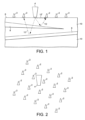
- FIG. 1 shows a schematic cross section of the surface and subsurface of the earth.
- Seismic sensors 2 and a seismic source 4 are shown on the surface of the earth 6.
- a number of layers of differing composition are present within the subsurface. These are illustrated by the interleaved black bands 8 and white bands 10.
- Seismic waves 12 emitted by the seismic source 4 travel through the subsurface. At the interfaces between the layers 8 and 10, these seismic waves are partially reflected and travel back to the surface to be detected by the seismic sensors 2.
- the seismic wave emitted by the seismic source 4 also travels along the surface or along the near surface as a direct wave 12'. Within close proximity from the source, these direct arrivals are detected by each seismic sensor 2 before the respective sensors detect any of the reflected waves. This first arrival is called the "first break”.
- a large number of seismic sensors are placed over an area of the surface of the earth above and around the volume of the subsurface to be surveyed.
- a typical survey may involve tens of thousands of seismic sensors spread over, for example 100 km 2 .
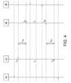
- Figure 2 shows an exemplary arrangement where a plurality of seismic sensors 2 are arranged in a grid pattern.
- a seismic source 4 is also illustrated surrounded by the seismic sensors 2. Naturally, there will be many more seismic sensors 2 than the twenty shown.
- Each seismic sensor has a sensing element capable of detecting the movement of the earth.
- the sensing element produces an output which reflects the movement of the earth.
- the output is sampled at regular intervals, for example every millisecond.
- This sampled data will be referred to as seismic data.
- the seismic data may be recorded against a sample number or index which increments for each sample. As such, the sample index may be considered a value indicative of time.
- the interval between consecutive samples is controlled by a local clock in the seismic sensor.
- the nominal (i.e. intended) sampling rate on different sensors participating in the survey is the same (ie. the same number of samples per second). This is not necessarily the case, and where nominal sampling rates differ, the seismic data recorded by one sensor may be re-sampled to enable comparisons between recorded signals.
- this accuracy is achieved by providing both the seismic source and the seismic sensor with high accuracy clocks. These clocks need to maintain a sufficient accuracy over the duration of the surveying operation, which may last many weeks.
- Drift means that the clocks do not increment at exactly the same rate. Drift may be caused by both manufacturing differences, and by local factors such as the ambient temperature around the seismic sensor.
- the magnitude of the drift can vary over time as, for example, the ambient temperature varies. Accordingly, such clocks may drift relative to both an external time signal (i.e. "system time” which may be provided by a high accuracy timing system such as a GPS timing system, as mentioned above) as well as relative to each other.
- system time an external time signal
- a high accuracy timing system such as a GPS timing system, as mentioned above
- US 6400646 discloses a system for synchronising a clock in a well containing a drill string with a clock located near the surface of the well.
- the system includes devices for transmitting and receiving a pair of acoustic signals between locations associated with each clock and processing those signals.
- the system determines the time of arrival of each acoustic signal by analysing the shape of a function of the acoustic signal chosen from a group of functions suitable to determine a clock offset with millisecond accuracy.
- US 6002640 discloses a seismic data acquisition system that utilises a series of nearly identical seismic shots (SISS) to synchronise and to communicate with novel data acquisition units (NDAU) located in the field. Each SISS is carefully timed to provide synchronisation to each NDAU, and to allow the NDAU to correct for the time drift of its internal clock.
- SISS nearly identical seismic shots
- NDAU novel data acquisition units
- US 2004/0117118 discloses techniques for determining the drift of a clock adapted for subsurface disposal. Seismic signals are transmitted through the subsurface medium from an uphole location at selected times, acoustic signals associated with the transmitted seismic signals are received with the acoustic sensors at identified downhole locations. First and second transit times for acoustic signals received at an identified downhole reference location are determined using the clock. A time difference between the first and second signal transit times at the reference point is calculated to determine the clock drift.
- US 2006/0203614 discloses a while-drilling Vertical Seismic Profiling (VSP) data acquisition system utilising the same seismic shots for three purposes.
- the shots provide a means for synchronising a downhole clock in the VSP receiver to a master clock at the surface, thereby enabling correct determination of seismic travel times.
- the same seismic shots are also used to communicate commands and other information to the downhole VSP receiver.
- the same seismic shots are utilised for purposes of the VSP survey itself.
- the present invention is as defined in the appended claims. Disclosed herein but not encompassed within the present claims is at least one apparatus and systems for supporting or implementing functionality to perform seismic surveying.
- the received data can be processed to identify the offset of the first clock.
- the method may comprise calculating an average of the first and second times and an average of the third and fourth times, the calculation of the offset being based on a difference between the calculated averages.
- the outputs of the first and second seismic sensors may further include components corresponding to the detection by the first and second seismic sensors of third and fourth seismic signals, a direction of propagation of the third seismic signal being from the first seismic sensor towards the second seismic sensor, and a direction of propagation of the fourth seismic signal being from the second seismic sensor towards the first seismic sensor.
- the method may further comprise:
- the output of at least one of the first and second seismic sensors may further include a component corresponding to the detection by said at least one seismic sensor, of a repeating seismic signal.
- the method can further comprise:
- a scaling factor may be determined for the clock of a seismic sensor.
- the offset and scaling factor can be applied to the time values recorded by the clock of said sensor to map said time values to a system time.
- the clock of said one of the seismic sensors can be calibrated relative to a reference clock, using the determined offset and scaling factor.
- the reference clock may be a highly accurate clock, such as a GPS one synchronised clock.
- the received data may further include an output of a third seismic sensor, the third seismic sensor having been located collinearly with the first and the second seismic sensors and having a third clock which is synchronised with the second clock.
- the method may further comprise:
- the method may comprise: calculating an average of the first and second times and an average of the third, fourth, fifth and sixth times, the offset being based on a difference of the calculated averages.
- more than one seismic sensor in this case the second and third may be used to calculate an offset for the clock of the first seismic sensor.
- the method can further comprise positioning first and second seismic sensors in an area and causing first and second seismic signals to be emitted so as to be sensed by the seismic sensors.
- Each seismic sensor may be provided with a clock such that times, relative to the clock, may be recorded associated with the sensing of the seismic signals.
- a first seismic signal is emitted from a seismic source collocated with the first seismic sensor.
- a second seismic signal emitted from a seismic source collocated with the second seismic sensor.
- the second seismic signal is emitted from a seismic source arranged collinearly with the first and second seismic sensors and such that the second seismic sensor is located between the seismic source and the first seismic sensor.
- the first seismic signal can be emitted from a seismic source arranged collinearly with the first and second seismic sensors and such that the first seismic sensor is located between the seismic source and the second seismic sensor.
- a seismic source and a seismic sensor may be collocated, for example by being part of a single device. This single device may then be used in the synchronising of a plurality of remote seismic sensors.
- a method of determining a scaling factor for a clock in a seismic sensor is disclosed herein but not encompassed within the scope of the present claims, the method comprising:
- a scaling factor may be determined for the clock of a seismic sensor using a periodic seismic signal. This scaling factor accounts for variations in the increment rate of a given clock, often known as drift. Being able to correct for drift ensures that the timings of seismic signals received by the seismic sensor can be accurately determined over a prolonged period.
- the identified time values can correspond to a given phase of the periodic seismic signal for a plurality of periods of the periodic seismic signal, and the scaling factor is determined based on a difference of the time values.
- the time values corresponding to peaks or maxima in the periodic seismic signal may be identified.
- the period of the periodic seismic signal would correspond to the difference in time values between adjacent peaks and a scaling factor may be determined accordingly.
- Time values, or differences in time values, may be averaged for a number of periods to provide a more accurate seismic signal.
- An alternative method of determining a scaling factor for the time values also falling outside of the scope of the present claims is to calculate the inner product of the received seismic signal with seismic signals of known periodic length.
- the inner product will generate a maximum when the two seismic signals are in phase.
- the period of the known seismic signal may then be used to determine the scaling factor.
- the periodic seismic signal may be a continuous monochromatic signal such as a sinusoidal seismic signal or it may comprise a plurality of discrete signals emitted at fixed intervals.
- fixed intervals it is meant that the time of emission is known, for example by recording the accurate time of emission in a memory.
- the interval may be constant.
- a seismic data set recorded by at least one seismic sensor can be received and the scaling factor for the clock in said seismic sensor can be used to correct the time measured by said clock.
- the seismic data set can comprise recorded signals corresponding to the periodic seismic signal and recorded signals corresponding to multiple seismic acquisition emissions.
- the seismic acquisition emissions are those emissions used to interrogate the subsurface. In this way, correction of the timing of the seismic data set is not performed until after the seismic data has been acquired. There is no real time correction. This can provide a simple and quick process with no specific burden on data handling or transfer in the field, during the survey.
- scaling factors can be determined, one scaling factor for a selected section of the seismic data set. For example, a scaling factor may be determined for each pair of consecutive time values. Alternatively, a scaling factor may be determined for each of a series of time intervals, such as every 20, 30 or 40 minutes of recoded data (the length of the time interval will depend on the degree that the clock is expected to drift).
- the method may further include the step of receiving offset data, corresponding to an initial offset, OFF, between the clock in each seismic sensor and a system time, said initial offset and scaling factor being used to correct the time measured by said clock.
- the time interval can be selected so that the drift does not vary significantly during the interval. In this way, the intervals can be corrected cumulatively.
- the invention provides methods which permit the use of low accuracy clocks in seismic sensors.
- Methods of the invention enable internal clocks in seismic sensors to be calibrated to a reference time ("system time"). Where a seismic source has an internal clock that is also calibrated to the system time, it is possible to determine the propagation time of a seismic wave from the source to the respective sensors accurately.
- system time is the time according to an accurate clock such as a GPS synchronised clock.
- Calibration of the internal clock of the seismic source to system time can optionally be achieved by providing the seismic source with an accurate internal clock.
- synchronising a first clock relative to a second clock is used to mean that the time value of the first clock has been brought in line with (i.e. is the same as) the time value of the second clock.
- the term “calibrating a first clock relative to a second clock” is used to mean that it is known how to map the time value of the first clock onto the time value of the second clock, for example by applying a correction factor to the time value of the first clock: the actual time value of the first clock is not modified to bring it in line with the second clock. It will be appreciated that synchronisation of the first clock to the second clock can be achieved after calibration by applying the correction factor and modifying the time value of the first clock.
- a first aspect involves calibrating the clocks in the sensors to a system time.
- System time is typically the time according to an accurate clock such as a GPS synchronised clock.
- this calibration process involves certain physical steps being carried out in the field before and/or during a seismic survey, the actual calibration is typically carried out offline after the sensors have been collected and the seismic data has been downloaded. That said, if the seismic data is transmitted from the sensors in real time to a processing facility, calibration could be commenced while the sensors are still collecting data in the field.
- the relationship in time of the seismic data recorded by one sensor is known relative to the seismic data recorded by the other sensors, which is important for processing the seismic data as a whole and for producing a seismic image. According to methods of the invention, this relationship is preferably established for an early stage of the seismic acquisition process. However, if the clocks drift at a non-constant rate, as is likely, the relationship changes, and so continued use of that same relationship will result in errors.
- the frequency of this re-calibration can depend on the likely, or expected, degree of drift: the more significant the drift, the more frequent the calibration process is repeated.
- a calibration process disclosed herein but not encompassed within the scope of the present claims involves (a) a particular physical arrangement of at least one seismic source and two seismic sensors, (b) the emission of two opposing seismic signals (described in more detail below) which are detected by the seismic sensors, and (c) specific data processing steps to calibrate the clock in one of the sensors relative to the clock in the other sensor.
- a number of seismic sensors 2 are positioned in an area of interest.
- two (2A and 2B) will be referred to in relation to Figure 4 .
- Two seismic sources 4A and 4B are arranged collinearly with the seismic sensors 2A and 2B.
- collinearly should be taken to mean that, when viewed from above, the seismic sensors and seismic sources are positioned along a line which is as close to straight as is practically possible.
- the seismic sensors and seismic sources may not be directly aligned along a single line, but rather that they are positioned in, as much as possible, the same vertical plane and on the earth's surface.
- Each seismic sensor has a clock.
- Seismic sensor 2A has a first clock whose time value will be represented by ⁇
- seismic sensor 2B has a second clock whose time value will be represented by t .
- One of the clocks for example that in seismic sensor 2B, has a known relationship with system time. This could be achieved, for example, by providing the clock with a GPS receiver so that the clock represents system time. Alternatively, the clock could previously have been calibrated to system time using the method described here and optionally then synchronised to system time.
- the seismic source 4A emits a first seismic signal
- the seismic source 4B emits a second seismic signal. Both seismic signals are sensed by the seismic sensors 2A and 2B.
- the seismic sensors 2A and 2B record time values, relative to the clock of the respective seismic sensor, indicative of the time of arrival (ToA) of the seismic signal at that seismic sensor.
- ToA time of arrival
- each sensor will detect the first break as well as at least one reflected wave.
- discussion of detecting the ToA of a seismic signal will relate to detecting the arrival of the first break at the sensor.
- subsequent data processing steps can include cross correlating the emitted signal with the recorded signal to help collapse the wavelet and identify the ToA of the signal at the seismic sensor.
- the signal emitted by source 4A and detected by sensor 2B propagates generally along the same path along/through the ground as the signal emitted by source 4B and detected by sensor 2A, but the direction of propagation of the two seismic signals is opposed. This is what is meant by "opposing seismic signals”. Accordingly, the travel time between sensor 2A and sensor 2B of the wave emitted by source 4A is the same as the travel time between sensor 2B and sensor 2A of the wave emitted by source 4B, provided the Earth's Green's Function is unchanged.
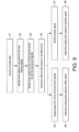
- Figure 4 shows a timing diagram for the system described above.
- the value of the clock in seismic sensor 2A is identified by ⁇
- the value of the clock in seismic sensor 2B is identified by t.
- the clock in seismic sensor 2B has a known relationship with system time. Indices will be used to identify the values of the clocks at given points in system time, i.e. ⁇ n refers to the time according to the clock in sensor 2A at system time n
- t n refers to the time according to the clock in sensor 2B at system time n.
- the signal emitted by source 4A is detected by sensor 2A at time ⁇ A1 . That signal progresses through the earth and is detected at sensor 2B at time t B1 . Similarly, the signal emitted by source 4B is detected by sensors 2B and 2A at times t B2 and ⁇ A2 respectively.
- ⁇ AB is the propagation time of the signal from sensor 2A to sensor 2B.
- ⁇ BA is the propagation time of the signal from sensor 2B to sensor 2A and is the same as ⁇ AB (if measured in system time).
- the two seismic signals emitted by sources 4A and 4B are emitted in relatively quick succession such that any drift of the clock in sensor 2A can be assumed to be constant.
- Zero time is a system time when the values of the clocks in sensors 2A and 2B are both known (explained further below).
- the difference in value between t 0 and ⁇ 0 is the offset ("OFF") between the clocks in sensors 2A and 2B at "zero time". In other words, it is the value needed to be added to the time measured by the clock in sensor 2A to map that clock to the clock in sensor 2B at zero time. It will be understood that the offset may be a positive or negative value.
- the offset can be used to map sensor 2A's ⁇ 0 value to system time.
- the scaling factor "a” it is possible to map any time value, ⁇ n , according to the clock in sensor 2A to the time, t n , according to the clock in sensor 2B (and consequently to system time).
- a second pair of opposing seismic signals is emitted, for example by seismic sources 4A and 4B.
- the second signal emitted by source 4A is detected by sensor 2A at time value ⁇ A3 , and by sensor 2B at time value t B3 .
- the second signal emitted by source 4B is detected by sensor 2B at time value t B4 , and by sensor 2A at time value ⁇ A4 .
- t 0 and ⁇ 0 are defined above as “zero time” for the first pair of opposing seismic shots
- the above enables calibration of the clock in sensor 2A with that in sensor 2B (and therefore with system time) for any point in the seismic data, assuming drift is constant. However, it has been found that clocks do not drift at a constant rate.
- the invention provides for emitting yet another pair of opposing seismic signals (i.e. a third pair of signals), for example one emission from each of seismic sources 4A and 4B, at a later point in time.
- the above process can be repeated so as to determine the scaling factor corresponding to the time period between the second and third pair of emissions.
- This recalibration process can be carried out at a frequency appropriate to the rate of change of drift in the clock in sensor 2A.
- the clock in sensor 2B is calibrated or synchronised to system time, for example GPS time. If the clock in sensor 2B is not itself a GPS synchronised clock (i.e. if it suffers from drift), then recalibration (and optionally re-synchronisation) of that clock will be required in order for the recalibration of the clock in sensor 2A to be meaningful.
- seismic sources are positioned and controlled to emit pairs of opposing seismic signals which are then recorded by the various sensors deployed in the field.
- two sources for example vibroseis trucks
- a seismic sensor is co-located with a first of the sources (either by providing a single unit which comprises a source and a sensor, or by locating a sensor adjacent to the source), and the seismic sensor is provided with a clock which is synchronised to GPS time.
- the two sources each emit a signal according to the description above. The propagation of those two signals is detected by the sensor associated with the first source as well as by each of the sensors in the receiver line.
- the two sources each emit a further signal, the propagation of which is detected by the sensor associated with the first source as well as by each of the sensors in the line.
- the sources will be used to emit a third pair of opposing seismic signals some time later. This may be a number of hours later or may be a day or more later, depending on how quickly the drift is likely to change. This re-calibration step may be repeated as many times as is needed throughout the seismic acquisition survey.
- the seismic sources it is not necessary for the seismic sources to remain in position between the first, second and subsequent signal-pair emissions. In fact, the sources can be moved to new positions during these periods to emit pairs of opposing seismic signals to be used in calibrating the clocks in other nearby receiver lines.
- the sources can be moved to opposing ends of another receiver line e.g. adjacent to the first line and the process can be repeated.
- the sources or a different pair of sources can be moved to opposing ends of a second receiver line arranged at an angle, for example perpendicular, to the first receiver line, provided that one of the receivers in this second receiver line was also part of the first receiver line.
- neither source has to have a sensor with an accurate clock associated with it.
- the sensor which was part of the first receiver line plays the role of the sensor with a known time, because the relationship of that sensor's clock can be determined in later processing and subsequently used as the accurate clock for the second receiver line.
- One, two or more pairs, as required, of opposing seismic signals are emitted for the second receiver line.
- seismic sources or further pairs of seismic sources are used and pairs of opposing seismic signals are emitted until all the sensors in the field have been part of a receiver line in accordance with the methods of this invention.
- the sensors are collected and the seismic data from each sensor is downloaded.
- the recorded data is analysed in accordance with the methods described above, to enable an understanding of the relationship between the time of its clock and GPS time.
- a first sensor in the first receiver line may be considered in connection with the sensor associated with the first source.
- the offset required to map the time of the clock in that first sensor to the GPS time of the sensor associated with the source, at "zero time" can be determined using equations (2) and (3) above.
- the scaling factor, a can be calculated using equation (8).
- the clock in the sensor under consideration can be recalibrated. This can be done either by determining the offset and scaling factor again using the second and third, or third and fourth etc pairs of opposing seismic signals, or by correcting the time in the clock under consideration using the first scaling factor for the first period and the second scaling factor for the second period etc.
- this latter method introduces a degree of error.
- a as described above, also disclosed herein but not encompassed within the scope of the present claims is a method to determine the scaling factor by emitting a further seismic signal from one side of the receiver line, for example from source 4A.
- a first seismic signal is emitted from one side of the receiver line, e.g. from source 4A as described above in connection with Figure 3 .
- a second seismic signal is emitted from the opposing side of the receiver line, e.g. from source 4B.
- a third seismic signal is emitted from the first side of the receiver line i.e. source 4A.
- the first and second seismic signals can be used to determine the offset required to map the time of the clock in sensor 2A to the clock in sensor 2B at "zero time” as described above.
- the third seismic signal can then be used to calculate the scaling factor as follows.
- the scaling factor can then be used in equation (4) to enable the mapping of the time of the clock in sensor 2A onto the time of the clock in sensor 2B at other times.
- the time according to the clock in sensor 2A between receiving the first seismic signal and the third seismic signal is determined.
- the time according to the clock in sensor 2B between receiving the first seismic signal and the third seismic signal is also determined.
- the ratio between these two time periods is the scaling factor, a.
- FIG. 5 a number of seismic sensors are shown positioned in an area of interest. Seismic sensors, 2A, 2B and 2C, will be referred to in relation to Figure 6 .
- Two seismic sources 4A and 4B are arranged collinearly with the seismic sensor 2A - that is seismic sensor 2A is located between the two seismic sources.
- Seismic sources 4A and 4B also comprise the seismic sensors 2C and 2B respectively.
- the combined seismic sensors and seismic sources may be formed as a single device, or simply be connected. In general, it can be said that the seismic sources are collocated with respective seismic sensors.
- seismic sensor 2A will have a first clock whose time value will be represented by ⁇ , however seismic sensors 2B and 2C will have clocks, collectively second clocks, which are synchronised with each other and therefore have the same time value, represented by t. These second clocks may be synchronised with system time.
- calibration data for the clocks 2B and 2C has already been determined, and that the time value attributed to one or both of the clocks represents a time value mapped via an equivalent of equation 1 above.
- the seismic source 4A emits a first seismic signal
- the seismic source 4B emits a second seismic signal. Both seismic signals are sensed by the seismic sensors 2A, 2B and 2C.
- the time of emission of the first seismic signal is the same as the ToA of the first seismic signal at the seismic sensor 2C, and is represented by t C1 .
- the ToA of the first seismic signal at seismic sensor 2A is then ⁇ A1
- the ToA of the first seismic signal at seismic sensor 2B is t B1
- the time of emission of the second seismic signal is the same as the ToA of the second seismic signal at the seismic sensor 2B, and is represented by t B2 .
- the ToA for the second seismic signal at seismic sensor 2A is ⁇ A2 and at seismic sensor 2C is t C2 .
- equation 2 above gives two values for t 0 .
- t 0 1 2 t C 1 + t C 2
- t 0 1 2 t B 1 + t B 2
- two seismic sensors 2B and 2C may be used to determine a more accurate calibration for the clock in the seismic sensor 2A. This may be particularly useful where the seismic sensor to be calibrated, in this example seismic sensor 2A is located between the other seismic sensors 2B and 2C as any variations in the propagation times of the seismic signal may be, at least partially, accounted for.
- one or both of the seismic sensors 2B and 2C may not be collocated with the seismic sensors 4B and 4A respectively. In the latter case, the seismic sensors and seismic sources may still be collinearly arranged.
- a given seismic sensor may be calibrated using more than two seismic signals, and with any number of other seismic sensors.
- Figure 7 illustrates how such an embodiment may operate.
- a plurality of pairs of seismic sources are arranged in different configurations such that at least one seismic sensor is collinear with the seismic sources.
- Seismic sources 4A and 4B are collinear with seismic sensor 2D and the four seismic sensors with reference 2E.
- Seismic sources 4C and 4D are collinear with seismic sensor 2D and the three seismic sensors with reference 2F.
- Seismic sources 4E and 4F are collinear with seismic sensor 2D and the three seismic sensors with reference 2G. This effect may be achieved by using more than two seismic sources, or by moving a pair of seismic sources between emissions of seismic signals.
- seismic sources 4A and 4B all of seismic sensors 2E may be calibrated in relation to seismic sensor 2D.
- seismic sources 4C and 4D may be used to calibrate seismic sensors 2F
- seismic sources 4E and 4F may be used to calibrate seismic sensors 2G.
- Seismic sensor 2D may be provided with an accurate clock calibrated with or synchronised to system time.
- a relatively small number of seismic sensors may be provided with accurate clocks, enabling these seismic sensors to be used to calibrate a relatively large number of surrounding seismic sensors.
- the seismic sensor 2D is not be provided with an accurate clock.
- each of the seismic sources 4A to 4F have seismic sensors (in line with the embodiment described above in relation to Figures 5 and 6 ). These may subsequently be used to calibrate the clock in the seismic sensor 2D multiple times with, e.g. an average being taken.
- the use of multiple calibrations ensures that the seismic sensor 2D is more accurately calibrated than if only one calibration was used. Consequently seismic sensor 2D may be used to calibrate surrounding seismic sensors.
- the drift over time of a clock in a sensor 2A can be corrected on a more continuous basis.
- the first step is to establish the initial offset of the clock in sensor 2A with respect to system time. This can optionally be achieved in accordance with the above method described in connection with Figures 3 to 6 , i.e. it can be established how the time value, ⁇ o , for the clock in sensor 2A can be mapped to the time value, t 0 , for the clock in sensor 2B, where the clock in sensor 2B is calibrated or synchronised to system time.
- This aspect involves emitting a repeating seismic signal throughout the geographical area of the seismic survey.
- the repeating signal is recorded like a time stamp in the seismic data of each seismic sensor. This time stamp can then be identified in later data processing steps to enable correction of the drift during data processing.
- a seismic source located in an acquisition area emits the repeating signal.
- the repeating signal can be a discrete signal such as an impulse or sweep which is repeated at a known, and typically constant, rate over the course of the survey.
- the repeating signal can be a continuous signal such as a monochromatic signal, for example a sinusoidal signal, which is emitted continuously over the course of the survey.
- the timing source can be arranged to emit its repeating signal starting from just before the first seismic sensor is deployed in the field. In this way, as soon as a sensor is deployed and switched on, it records the repeating signal.
- the propagation time of a discrete signal from the timing source to any given seismic sensor is unknown, the propagation time is constant over the course of the survey (provided the Earth's Green's function remains the same).
- the time between specific repeating points on the sinusoidal signal (e.g. the peaks of the waveform) are constant over the course of the survey.
- the sensors are collected from the field and the data downloaded.
- the data could be communicated in real time to a data collection unit, while the seismic acquisition survey is ongoing.
- Figure 8 shows a depiction of a seismic source 4S emitting a discrete signal, p.
- the source 4S is provided with a GPS synchronised clock so that the emission times are accurately controlled to a pre-set periodicity, l t .
- a seismic sweep say of 10 seconds duration, may be emitted every 30 minutes.
- the source 4S emits each signal from the same location, to ensure that the propagation time to each sensor 2 is constant for each repetition.
- the propagated discrete signal recorded by sensor 2A can be identified by cross correlating the emitted seismic sweep with the recorded data to determine the ToA of the discrete signal at the sensor ( ⁇ p1 , ⁇ p2 , ⁇ p3 etc).
- the offset between the clock in sensor 2A and system time (e.g. GPS time) has already been established, for example by way of the method described above. Accordingly, the ratio between the periodicity, l t , and the difference in time between the ToAs of consecutive discrete signals (i.e. ⁇ 1 , ⁇ 2 etc) can be used to determine the relationship between the time of the clock in sensor 2A and system time.
- the frequency of emission of the discrete signal is chosen such that the level of drift likely to occur between two consecutive discrete signals is low.
- Drift in the clock in sensor 2A between the point at which the offset has been determined (i.e. ⁇ 0 for the above method of establishing offset) and the ToA of the first discrete signal following ⁇ 0 can be treated as zero.
- t m t pn + A pn . ⁇ m ⁇ pn where "pn" corresponds to the last discrete signal recorded before ⁇ m .
- a potentially more accurate value for t p1 may be obtained by calculating the scaling factor, A, for the time period between ⁇ p1 and ⁇ p(-1) , where ⁇ p(-1) , is the ToA of the last discrete signal recorded by the sensor before ⁇ 0 . It will be understood that discrete signals are recorded before ⁇ 0 because emission of the discrete signal is commenced before the sensors are deployed/switched on.
- the timing source need not remain in the same location in the survey area throughout the survey.
- the timing source can instead progress along the survey area as the acquisition process progresses.
- a seismic source taking part in the seismic acquisition survey may be used to carry out the second function of emitting the discrete signal.
- the source can emit discrete signals from the same location while the sensors are being deployed in the field. Once the sensors are deployed, the source can start moving around the acquisition area emitting signals for the purpose of the acquisition process.
- shot point it is meant a location at which the source emitted a "shot” i.e. seismic signal for the purpose of seismic acquisition. This will be different to the location at which the previous discrete signals were emitted. Because the source has already emitted a signal from that shot point at a time that has been precisely recorded for the purpose of the seismic acquisition, a second shot emitted from that same location can be used in a similar way to the method described above, to enable the times of inaccurate clocks on sensors to be mapped onto system time.
- the time between consecutive discrete signals need not be constant, provided at least two signals are emitted from any given location and the exact times of those emissions are known.
- timing source may be used to ensure all sensors in the area detect the discrete signal.
- the discrete signal emitted by the different timing sources may be different, for example different sweeps, to enable the relevant discrete signal to be isolated during processing.
- the signal is emitted from a stationary source.
- the periodic length of the signal is a known constant, and so the scaling factor may be determined by comparing the periodic length of the signal measured by the sensor and the known periodic length.
- a notch filter can be applied to isolate the monochromatic signal recorded by the sensor.
- the width of the notch filter can be selected to capture the expected distortion in the recorded signal caused by drift in the clock.
- a notch filter may not be necessary if the techniques (described below) for determining the frequency of the recorded timing signal are sufficient. However, a notch filter may be beneficial if the timing signal is weak or the background noise, for example from other seismic activity, is relatively large.
- a number of techniques are known to the skilled person for determining the frequency of a signal. This determined frequency can then be compared to the known frequency of the emitted timing signal.
- an inner product of the measured waveform at a selected time and sample waveforms having known periodic lengths can be calculated.
- the sample which provides the largest inner product has a periodic length which most closely matches the periodic length of the waveform measured by the sensor, and so that periodic length is said to be the measured periodic length, which is used to determine the scaling factor, a.
- the emitted signal and the recorded signal can be compared using a warping function such as used in dynamic warping or optical image warping, to determine how the emitted signal has been changed due to clock drift.
- the periodic length of the recorded signal can be determined using this change.
- a Fourier transform may be used to determine the frequency components present in the recorded data, so as to determine how much the frequency has changed. Accordingly, the periodic length of the recorded data can then be determined.
- the Hilbert transform a well known linear operator, can be used to analyse the signal measured by the sensor at a given time, to determine the instantaneous frequency of the measured signal. This frequency, so determined, can be compared to the known frequency of the emitted signal.
- the system time corresponding to any time according to the clock in a sensor 2 can be determined by starting from the point at which the offset has been determined and applying the scaling factor to the time recorded by the clock in the sensor. If the drift is likely to vary over time, the recorded data may be split into discrete sections and a scaling factor may be calculated for each discrete section such that the time can be corrected cumulatively.
- a general method of calibrating a clock in a seismic sensor will be described with reference to Figure 9 .
- a first step 21 data recorded by the seismic sensors is received.
- times relative to the first clock for a first and second signal are identified. These may be the ToA times for the first and second signals described above.
- steps 23 times relative to one or more second clocks are identified for the first and second signals.
- the offset of the first clock is determined based on the identified times. This may be done by taking an average of the times relative to the first clock, and an average of the times relative to the one or more second clocks, and differencing the averages.
- a scaling factor is determined by steps 25 and 26, in an alternative embodiment disclosed herein but not encompassed within the scope of the present claims, the scaling factor may be determined by steps 27 and 28 (or a combination of the two).
- step 25 step 22 to 24 above are repeated for a third and fourth signal. These may be used to determine an offset for the first clock at a later time. Based on the two offset values the scaling factor may be determined using, for example, equation 8 above.
- step 27 a timing signal is identified in the received data. This periodic signal may be used, in step 28, to determine the scaling factor.
- the above methods may be conducted by a suitable computer system.
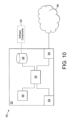
- a schematic block diagram showing such a computer system 50 will now be described with reference to Figure 10 .
- the computer system 50 comprises a processing system 52 having a processor, or CPU, 54 which is connected to a volatile memory (i.e. RAM) 56 and a non-volatile memory (such as a hard drive or a removable memory such as a disk or flash drive) 58.
- Software components 60 carrying instructions for implementing embodiments of the invention, may be stored in the non-volatile memory 58 and/or volatile memory 56.
- CPU 54 may be connected to a user interface 62 and a network interface 64.
- the network interface 64 may be a wired or wireless interface and is connected to a network, represented by cloud 66.
- the processing system 52 may be connected with seismic sensors, databases and other seismic sources and receivers of data through the network 66.
- the processor 54 retrieves and executes the stored software components 60, for example from the non-volatile memory 58. During the execution of the software components 60 (that is when the computer system is performing the actions described above) the processor may store data temporarily in the volatile memory 56. The processor 54 may also receive data, through user interface 62 and network interface 64, as required to implement embodiments of the invention. In some embodiments, a retrieval system for retrieving data from the seismic sensors may be provided and connected to the computer system 50 via interface 64.
- the computer system 50 may also be used to interpret any seismic survey data acquired by any seismic surveying methods as known in the art. Alternatively, the computer system may provide an output via either of the user interface 62 or the network interface 64 which can be used by other systems to perform the surveying methods.
- Regular samples of a may be taken to determine this function, with, for example, a(t) being interpolated between samples.
Landscapes
- Engineering & Computer Science (AREA)
- Remote Sensing (AREA)
- Physics & Mathematics (AREA)
- Life Sciences & Earth Sciences (AREA)
- Acoustics & Sound (AREA)
- Environmental & Geological Engineering (AREA)
- Geology (AREA)
- General Life Sciences & Earth Sciences (AREA)
- General Physics & Mathematics (AREA)
- Geophysics (AREA)
- Geophysics And Detection Of Objects (AREA)
Claims (9)
- Procédé comprenant :l'émission, par une première source sismique (4A) positionnée sur une surface de la Terre, d'un premier signal sismique, dans lequel la première source sismique (4A), un premier capteur sismique (2A), un deuxième capteur sismique (2B), et une seconde source sismique (4B) sont chacun positionnés de manière colinéaire à des emplacements séparés le long d'une ligne droite, et dans lequel une direction de propagation du premier signal sismique s'étend à partir du premier capteur sismique (2A) vers le deuxième capteur sismique (2B) ;la détection, par le premier capteur sismique (2A) positionné sur la surface de la Terre, du premier signal sismique ;la détection, par le deuxième capteur sismique (2B) positionné sur la surface de la Terre, du premier signal sismique ;l'émission, par la seconde source sismique (4B) positionnée sur la surface de la Terre, d'un deuxième signal sismique, dans lequel la seconde source sismique (4B) est disposée de manière colinéaire avec le premier capteur sismique (2A) et le deuxième capteur sismique (2B), dans lequel une direction de propagation du deuxième signal sismique s'étend à partir du deuxième capteur sismique (2B) vers le premier capteur sismique (2A), et dans lequel la direction de propagation du premier signal sismique s'oppose à la direction de propagation du deuxième signal sismique ;la détection, par le premier capteur sismique (2A), du deuxième signal sismique ;la détection, par le deuxième capteur sismique (2B), du deuxième signal sismique ;l'identification, par rapport à une première horloge dans le premier capteur sismique, d'un premier temps (TA1) associé à un temps d'arrivée du premier signal sismique au niveau du premier capteur sismique, et d'un deuxième temps (TA2) associé à un temps d'arrivée du deuxième signal sismique au niveau du premier capteur sismique ;l'identification, par rapport à une deuxième horloge dans le deuxième capteur sismique, d'un troisième temps (TB1) associé à un temps d'arrivée du premier signal sismique au niveau du deuxième capteur sismique, et d'un quatrième temps (TB1) associé à un temps d'arrivée du deuxième signal sismique au niveau du deuxième capteur sismique ; etla détermination d'un décalage de la première horloge par rapport à la deuxième horloge à l'aide du premier temps, du deuxième temps, du troisième temps, et du quatrième temps.
- Procédé selon la revendication 1, comprenant en outre le calcul d'une moyenne du premier temps et du deuxième temps et d'une moyenne du troisième temps et du quatrième temps, dans lequel le décalage est déterminé sur la base d'une différence entre la moyenne du premier temps et du deuxième temps et la moyenne du troisième temps et du quatrième temps.
- Procédé selon la revendication 1 ou la revendication 2, dans lequel les sorties du premier capteur sismique (2A) et du deuxième capteur sismique (2B) incluent en outre des composantes correspondant à une détection d'un troisième signal sismique et d'un quatrième signal sismique, dans lequel une direction de propagation du troisième signal sismique s'étend à partir du premier capteur sismique vers le deuxième capteur sismique, dans lequel une direction de propagation du quatrième signal sismique s'étend à partir du deuxième capteur sismique vers le premier capteur sismique, dans lequel le procédé comprend en outre :l'identification, par rapport à la première horloge dans le premier capteur sismique, d'un cinquième temps associé à un temps d'arrivée du troisième signal sismique au niveau du premier capteur sismique, et d'un sixième temps associé à un temps d'arrivée du quatrième signal sismique au niveau du premier capteur sismique ;l'identification, par rapport à une deuxième horloge dans le deuxième capteur sismique, d'un septième temps associé à un temps d'arrivée du troisième signal sismique au niveau du deuxième capteur sismique, et d'un huitième temps associé à un temps d'arrivée du quatrième signal sismique au niveau du deuxième capteur sismique ; etla détermination d'un facteur d'échelle (A) pour la première horloge à l'aide du premier temps, du deuxième temps, du troisième temps, du quatrième temps, du cinquième temps, du sixième temps, du septième temps, et du huitième temps.
- Procédé selon la revendication 1 ou la revendication 2, dans lequel la sortie d'au moins l'un du premier capteur sismique (2A) ou du deuxième capteur sismique (2B) inclut en outre une composante correspondant à une détection d'un signal sismique répétitif (p) émis par l'au moins de la première source sismique (4A) ou de la seconde source sismique (4B), dans lequel le procédé comprend en outre :l'identification d'une période du signal sismique répétitif (p) dans la sortie de l'au moins une de la première source sismique (4A) ou de la seconde source sismique (4B) ; etla détermination d'un facteur d'échelle (A) pour l'horloge de l'au moins un du premier capteur sismique (2A) ou du deuxième capteur sismique (2B) en comparant la période identifiée du signal sismique répétitif (p) dans la sortie avec une période réelle connue du signal sismique répétitif (p).
- Procédé selon la revendication 3 ou la revendication 4, comprenant en outre l'étalonnage de l'horloge de l'au moins un du premier capteur sismique (2A) ou du deuxième capteur sismique (2B) par rapport à une horloge de référence, à l'aide du décalage et du facteur d'échelle.
- Procédé selon l'une quelconque des revendications précédentes, dans lequel les données incluent en outre une sortie d'un troisième capteur sismique (2C), dans lequel le troisième capteur sismique est situé de manière colinéaire avec le premier capteur sismique (2A) et le deuxième capteur sismique (2B), et dans lequel le troisième capteur sismique possède une troisième horloge qui est synchronisée avec la deuxième horloge, dans lequel le procédé comprend en outre :l'identification, par rapport à la troisième horloge dans le troisième capteur sismique, de deux autres temps (tc1, tc2) associés à des temps d'arrivée du premier signal sismique et du deuxième signal sismique au niveau du troisième capteur sismique ; etla détermination d'un décalage de la première horloge par rapport aux deuxième et troisième horloges à l'aide du premier temps, du deuxième temps, du troisième temps, du quatrième temps, et des deux autres temps.
- Procédé selon la revendication 6, comprenant :
le calcul d'une moyenne du premier temps et du deuxième temps et d'une moyenne du troisième temps, du quatrième temps, du cinquième temps, et du sixième temps, dans lequel le décalage de la première horloge par rapport aux deuxième et troisième horloges est basé sur une différence entre la moyenne du premier temps et du deuxième temps et la moyenne du troisième temps, du quatrième temps, du cinquième temps, et du sixième temps. - Procédé selon la revendication 1, dans lequel le deuxième capteur sismique (2B) est situé entre la première source sismique (4A) et la seconde source sismique (4B).
- Procédé de détermination d'un facteur d'échelle (A) pour une première horloge dans un premier capteur sismique (2A), le procédé comprenant :la détection, par le premier capteur sismique (2A), d'un premier signal sismique émis par une première source sismique (4A), dans lequel une direction de propagation du premier signal sismique s'étend à partir du premier capteur sismique (2A) vers un deuxième capteur sismique (2B) ;la détection, par un deuxième capteur sismique (2B), du premier signal sismique émis par la première source sismique (4A) ;la détection, par le deuxième capteur sismique (2B), d'un deuxième signal sismique émis par une seconde source sismique (4B), dans lequel une direction de propagation du deuxième signal sismique s'étend à partir du deuxième capteur sismique (2B) vers le premier capteur sismique (2A), dans lequel la direction de propagation du premier signal sismique s'oppose à la direction de propagation du deuxième signal sismique ;la détection, par le premier capteur sismique (2A), du deuxième signal sismique émis par la seconde source sismique (4B),dans lequel le premier signal sismique et le deuxième signal sismique sont détectés de manière répétée par le premier capteur sismique (2A) et le deuxième capteur sismique (2B) sur une pluralité de périodes de temps, etdans lequel le premier capteur sismique (2A), le deuxième capteur sismique (2B), la première source sismique (4A), et une seconde source sismique (4B) sont chacun positionnés de manière colinéaire sur une surface de la Terre à des emplacements séparés le long d'une ligne droite ;l'identification, par rapport à la première horloge dans le premier capteur sismique (2A), de premières valeurs temporelles ('Lp) correspondant au premier signal sismique et au deuxième signal sismique, dans lequel chacune des premières valeurs temporelles ('Lp) correspond à une phase du premier signal sismique et du deuxième signal sismique pour différentes périodes de la pluralité de périodes de temps ;l'identification, par rapport à la deuxième horloge dans le deuxième capteur sismique (2B), de secondes valeurs temporelles ('Lp) correspondant au premier signal sismique et au deuxième signal sismique, dans lequel chacune des secondes valeurs temporelles ('Lp) correspond à une phase du premier signal sismique et du deuxième signal sismique pour différentes périodes de la pluralité de périodes de temps ;la détermination d'un facteur d'échelle pour les premières valeurs temporelles de la première horloge sur la base d'un rapport entre les secondes valeurs temporelles du premier signal sismique et du deuxième signal sismique et les premières valeurs temporelles du premier signal sismique et du deuxième signal sismique.
Applications Claiming Priority (2)
| Application Number | Priority Date | Filing Date | Title |
|---|---|---|---|
| US201562138629P | 2015-03-26 | 2015-03-26 | |
| PCT/EP2016/056431 WO2016151037A1 (fr) | 2015-03-26 | 2016-03-23 | Procédé d'étude sismique |
Publications (2)
| Publication Number | Publication Date |
|---|---|
| EP3274739A1 EP3274739A1 (fr) | 2018-01-31 |
| EP3274739B1 true EP3274739B1 (fr) | 2025-03-05 |
Family
ID=55637363
Family Applications (1)
| Application Number | Title | Priority Date | Filing Date |
|---|---|---|---|
| EP16712025.2A Active EP3274739B1 (fr) | 2015-03-26 | 2016-03-23 | Procédé d'étude sismique |
Country Status (7)
| Country | Link |
|---|---|
| US (1) | US10928532B2 (fr) |
| EP (1) | EP3274739B1 (fr) |
| CN (1) | CN107923991B (fr) |
| DK (1) | DK3274739T3 (fr) |
| ES (1) | ES3024998T3 (fr) |
| RU (1) | RU2729952C2 (fr) |
| WO (1) | WO2016151037A1 (fr) |
Families Citing this family (5)
| Publication number | Priority date | Publication date | Assignee | Title |
|---|---|---|---|---|
| US11194069B2 (en) * | 2017-12-15 | 2021-12-07 | Halliburton Energy Services, Inc. | Systems and methods for high-resolution travel time and move-out velocity estimation using downhole linear receiver arrays |
| CN111381487B (zh) * | 2018-12-29 | 2022-01-11 | 阿里巴巴集团控股有限公司 | 多传感器同步授时系统、方法、装置及电子设备 |
| GB201914919D0 (en) * | 2019-10-15 | 2019-11-27 | Bp Exploration Operating Co Ltd | Clock drift |
| TWI801217B (zh) * | 2022-04-25 | 2023-05-01 | 華碩電腦股份有限公司 | 訊號異常檢測系統及其方法 |
| CN115857011B (zh) * | 2022-12-09 | 2023-06-20 | 中国科学院地质与地球物理研究所 | 一种基于区域最优化拟合求取地震计传递函数的方法 |
Family Cites Families (24)
| Publication number | Priority date | Publication date | Assignee | Title |
|---|---|---|---|---|
| US6002640A (en) * | 1997-05-15 | 1999-12-14 | Geo-X Systems, Inc. | Seismic data acquisition system |
| US6424595B1 (en) | 1999-03-17 | 2002-07-23 | Baker Hughes Incorporated | Seismic systems and methods with downhole clock synchronization |
| US6400646B1 (en) * | 1999-12-09 | 2002-06-04 | Halliburton Energy Services, Inc. | Method for compensating for remote clock offset |
| US7269095B2 (en) | 2002-10-04 | 2007-09-11 | Aram Systems, Ltd. | Synchronization of seismic data acquisition systems |
| US6912465B2 (en) * | 2002-12-12 | 2005-06-28 | Schlumberger Technology Corporation | System and method for determining downhole clock drift |
| US6837105B1 (en) * | 2003-09-18 | 2005-01-04 | Baker Hughes Incorporated | Atomic clock for downhole applications |
| US7551516B2 (en) * | 2005-03-09 | 2009-06-23 | Aram Systems, Ltd. | Vertical seismic profiling method utilizing seismic communication and synchronization |
| FR2889331B1 (fr) * | 2005-07-28 | 2008-02-01 | Sercel Sa | Appareil et procede de compensation de derive d'une horloge locale utilisee comme frequence d'echantillonnage |
| CA2630470C (fr) * | 2005-11-15 | 2015-01-06 | Baker Hughes Incorporated | Annulation amelioree du bruit dans des mesures de type vsp |
| GB2443248A (en) * | 2006-10-23 | 2008-04-30 | Conor Keegan | Seismography system using GPS timing signals |
| US8902695B2 (en) | 2006-12-06 | 2014-12-02 | Baker Hughes Incorporated | Apparatus and method for clock shift correction for measurement-while-drilling measurements |
| US8605543B2 (en) * | 2007-09-21 | 2013-12-10 | Fairfield Industries Incorporated | Method and apparatus for correcting the timing function in a nodal seismic data acquisition unit |
| CN103064109B (zh) * | 2008-11-04 | 2017-07-18 | 费尔菲尔德工业公司 | 用于校正节点地震数据采集单元中的计时功能的方法和装置 |
| US8594962B2 (en) * | 2009-05-28 | 2013-11-26 | Westerngeco L.L.C. | Distributing a clock in a subterranean survey data acquisition system |
| WO2011068922A2 (fr) * | 2009-12-03 | 2011-06-09 | Shell Oil Company | Correction de synchronisation d'horloge sismique utilisant les ondes acoustiques de l'océan |
| US9217804B2 (en) * | 2010-03-26 | 2015-12-22 | Shell Oil Company | Seismic clock timing correction using ocean acoustic waves |
| US8995222B2 (en) * | 2010-05-06 | 2015-03-31 | Bp Corporation North America Inc. | System and method for accurate determination of ocean bottom seismometer positioning and timing |
| CN101986095B (zh) * | 2010-09-14 | 2012-01-11 | 天津大学 | 一种消除晶振时间漂移的地面标记方法 |
| GB2491103B (en) * | 2011-05-17 | 2017-05-17 | Sonardyne Int Ltd | System for measuring a time offset and method of measuring a time offset |
| US9250347B2 (en) * | 2011-06-10 | 2016-02-02 | Baker Hughes Incorporated | Method to look ahead of the bit |
| US9429120B2 (en) * | 2012-10-29 | 2016-08-30 | Woodward, Inc. | Detecting leaks in a feedthrough device |
| US20140297189A1 (en) * | 2013-03-26 | 2014-10-02 | Cgg Services Sa | Seismic systems and methods employing repeatability shot indicators |
| US20150003200A1 (en) * | 2013-06-28 | 2015-01-01 | Mike Hall | System and method for determining the position of a sensor in seismic exploration |
| PL225485B1 (pl) * | 2014-11-19 | 2017-04-28 | Inst Technik Innowacyjnych Emag | Sposób i układ do synchronizacji sejsmicznych i sejsmoakustycznych sieci pomiarowych, zwłaszcza kopalnianych sieci iskrobezpiecznych |
-
2016
- 2016-03-23 EP EP16712025.2A patent/EP3274739B1/fr active Active
- 2016-03-23 DK DK16712025.2T patent/DK3274739T3/da active
- 2016-03-23 WO PCT/EP2016/056431 patent/WO2016151037A1/fr not_active Ceased
- 2016-03-23 CN CN201680030531.2A patent/CN107923991B/zh active Active
- 2016-03-23 ES ES16712025T patent/ES3024998T3/es active Active
- 2016-03-23 US US15/558,560 patent/US10928532B2/en active Active
- 2016-03-23 RU RU2017134844A patent/RU2729952C2/ru active
Also Published As
| Publication number | Publication date |
|---|---|
| CN107923991A (zh) | 2018-04-17 |
| RU2017134844A (ru) | 2019-04-26 |
| ES3024998T3 (en) | 2025-06-05 |
| RU2017134844A3 (fr) | 2019-07-17 |
| EP3274739A1 (fr) | 2018-01-31 |
| CN107923991B (zh) | 2021-03-30 |
| WO2016151037A1 (fr) | 2016-09-29 |
| DK3274739T3 (da) | 2025-05-12 |
| US10928532B2 (en) | 2021-02-23 |
| US20180203142A1 (en) | 2018-07-19 |
| RU2729952C2 (ru) | 2020-08-13 |
Similar Documents
| Publication | Publication Date | Title |
|---|---|---|
| EP3274739B1 (fr) | Procédé d'étude sismique | |
| US9176242B2 (en) | Practical autonomous seismic recorder implementation and use | |
| KR101548976B1 (ko) | 지진 표면파들의 파형들을 사용하는 토양 특성들의 추정 | |
| US8467267B2 (en) | Asynchronous operation of seismic sources in a seismic survey | |
| RU2422856C2 (ru) | Способ учета растяжения сейсмического импульса в сейсмических данных | |
| EP2856214B1 (fr) | Analyse de données sismiques au moyen d'une collecte de données de noeuds de fond océanique | |
| US8842493B2 (en) | Method for offset timing of simultaneous seismic source firing | |
| EA014281B1 (ru) | Способ проведения сейсмической разведки | |
| CN103782198A (zh) | 使用光纤分布式感测装置的地震地球物理勘测 | |
| US8958267B2 (en) | Seismic true estimated wavelet | |
| EP2073041A1 (fr) | Méthode pour éstimer un parametre d'un rayon sismique dans un sismogramme | |
| CN110426741B (zh) | 一种地震噪音成像勘探方法、装置和存储介质 | |
| RU2436130C2 (ru) | Способ и система радиолокационного зондирования земных недр | |
| US6459993B1 (en) | Processing sonic waveform measurements from array borehole logging tools | |
| EA005232B1 (ru) | Способ и устройство обработки сейсмических данных | |
| US10371847B2 (en) | System and methodology for identifying time differences between clocks during seismic exploration | |
| US4813026A (en) | Method for logarithmic analysis of seismic reflection signals | |
| Blacquière et al. | 3-D physical modeling for acquisition geometry studies | |
| RU2572668C1 (ru) | Способ определения местоположения бурового инструмента в процессе бурения | |
| US20140254308A1 (en) | Identifying reflection acoustic signals | |
| CN121142641A (zh) | 基于vsp数据的时深关系校正方法和装置 | |
| WO2026010507A1 (fr) | Procédé de correction de dérive d'horloge |
Legal Events
| Date | Code | Title | Description |
|---|---|---|---|
| STAA | Information on the status of an ep patent application or granted ep patent |
Free format text: STATUS: THE INTERNATIONAL PUBLICATION HAS BEEN MADE |
|
| PUAI | Public reference made under article 153(3) epc to a published international application that has entered the european phase |
Free format text: ORIGINAL CODE: 0009012 |
|
| STAA | Information on the status of an ep patent application or granted ep patent |
Free format text: STATUS: REQUEST FOR EXAMINATION WAS MADE |
|
| 17P | Request for examination filed |
Effective date: 20171004 |
|
| AK | Designated contracting states |
Kind code of ref document: A1 Designated state(s): AL AT BE BG CH CY CZ DE DK EE ES FI FR GB GR HR HU IE IS IT LI LT LU LV MC MK MT NL NO PL PT RO RS SE SI SK SM TR |
|
| AX | Request for extension of the european patent |
Extension state: BA ME |
|
| DAV | Request for validation of the european patent (deleted) | ||
| DAX | Request for extension of the european patent (deleted) | ||
| STAA | Information on the status of an ep patent application or granted ep patent |
Free format text: STATUS: EXAMINATION IS IN PROGRESS |
|
| 17Q | First examination report despatched |
Effective date: 20201029 |
|
| GRAP | Despatch of communication of intention to grant a patent |
Free format text: ORIGINAL CODE: EPIDOSNIGR1 |
|
| STAA | Information on the status of an ep patent application or granted ep patent |
Free format text: STATUS: GRANT OF PATENT IS INTENDED |
|
| INTG | Intention to grant announced |
Effective date: 20240926 |
|
| GRAS | Grant fee paid |
Free format text: ORIGINAL CODE: EPIDOSNIGR3 |
|
| GRAA | (expected) grant |
Free format text: ORIGINAL CODE: 0009210 |
|
| STAA | Information on the status of an ep patent application or granted ep patent |
Free format text: STATUS: THE PATENT HAS BEEN GRANTED |
|
| AK | Designated contracting states |
Kind code of ref document: B1 Designated state(s): AL AT BE BG CH CY CZ DE DK EE ES FI FR GB GR HR HU IE IS IT LI LT LU LV MC MK MT NL NO PL PT RO RS SE SI SK SM TR |
|
| REG | Reference to a national code |
Ref country code: GB Ref legal event code: FG4D |
|
| REG | Reference to a national code |
Ref country code: CH Ref legal event code: EP |
|
| P01 | Opt-out of the competence of the unified patent court (upc) registered |
Free format text: CASE NUMBER: APP_6619/2025 Effective date: 20250207 |
|
| REG | Reference to a national code |
Ref country code: IE Ref legal event code: FG4D |
|
| REG | Reference to a national code |
Ref country code: DE Ref legal event code: R096 Ref document number: 602016091434 Country of ref document: DE |
|
| REG | Reference to a national code |
Ref country code: DK Ref legal event code: T3 Effective date: 20250506 |
|
| REG | Reference to a national code |
Ref country code: ES Ref legal event code: FG2A Ref document number: 3024998 Country of ref document: ES Kind code of ref document: T3 Effective date: 20250605 |
|
| REG | Reference to a national code |
Ref country code: NL Ref legal event code: FP |
|
| PG25 | Lapsed in a contracting state [announced via postgrant information from national office to epo] |
Ref country code: RS Free format text: LAPSE BECAUSE OF FAILURE TO SUBMIT A TRANSLATION OF THE DESCRIPTION OR TO PAY THE FEE WITHIN THE PRESCRIBED TIME-LIMIT Effective date: 20250605 |
|
| PG25 | Lapsed in a contracting state [announced via postgrant information from national office to epo] |
Ref country code: FI Free format text: LAPSE BECAUSE OF FAILURE TO SUBMIT A TRANSLATION OF THE DESCRIPTION OR TO PAY THE FEE WITHIN THE PRESCRIBED TIME-LIMIT Effective date: 20250305 |
|
| PGFP | Annual fee paid to national office [announced via postgrant information from national office to epo] |
Ref country code: ES Payment date: 20250401 Year of fee payment: 10 |
|
| REG | Reference to a national code |
Ref country code: LT Ref legal event code: MG9D |
|
| PG25 | Lapsed in a contracting state [announced via postgrant information from national office to epo] |
Ref country code: HR Free format text: LAPSE BECAUSE OF FAILURE TO SUBMIT A TRANSLATION OF THE DESCRIPTION OR TO PAY THE FEE WITHIN THE PRESCRIBED TIME-LIMIT Effective date: 20250305 |
|
| PG25 | Lapsed in a contracting state [announced via postgrant information from national office to epo] |
Ref country code: LV Free format text: LAPSE BECAUSE OF FAILURE TO SUBMIT A TRANSLATION OF THE DESCRIPTION OR TO PAY THE FEE WITHIN THE PRESCRIBED TIME-LIMIT Effective date: 20250305 |
|
| PG25 | Lapsed in a contracting state [announced via postgrant information from national office to epo] |
Ref country code: GR Free format text: LAPSE BECAUSE OF FAILURE TO SUBMIT A TRANSLATION OF THE DESCRIPTION OR TO PAY THE FEE WITHIN THE PRESCRIBED TIME-LIMIT Effective date: 20250606 Ref country code: BG Free format text: LAPSE BECAUSE OF FAILURE TO SUBMIT A TRANSLATION OF THE DESCRIPTION OR TO PAY THE FEE WITHIN THE PRESCRIBED TIME-LIMIT Effective date: 20250305 |
|
| REG | Reference to a national code |
Ref country code: AT Ref legal event code: MK05 Ref document number: 1773392 Country of ref document: AT Kind code of ref document: T Effective date: 20250305 |
|
| PG25 | Lapsed in a contracting state [announced via postgrant information from national office to epo] |
Ref country code: SE Free format text: LAPSE BECAUSE OF FAILURE TO SUBMIT A TRANSLATION OF THE DESCRIPTION OR TO PAY THE FEE WITHIN THE PRESCRIBED TIME-LIMIT Effective date: 20250305 |
|
| PG25 | Lapsed in a contracting state [announced via postgrant information from national office to epo] |
Ref country code: SM Free format text: LAPSE BECAUSE OF FAILURE TO SUBMIT A TRANSLATION OF THE DESCRIPTION OR TO PAY THE FEE WITHIN THE PRESCRIBED TIME-LIMIT Effective date: 20250305 |
|
| PG25 | Lapsed in a contracting state [announced via postgrant information from national office to epo] |
Ref country code: PT Free format text: LAPSE BECAUSE OF FAILURE TO SUBMIT A TRANSLATION OF THE DESCRIPTION OR TO PAY THE FEE WITHIN THE PRESCRIBED TIME-LIMIT Effective date: 20250707 |
|
| PG25 | Lapsed in a contracting state [announced via postgrant information from national office to epo] |
Ref country code: PL Free format text: LAPSE BECAUSE OF FAILURE TO SUBMIT A TRANSLATION OF THE DESCRIPTION OR TO PAY THE FEE WITHIN THE PRESCRIBED TIME-LIMIT Effective date: 20250305 |
|
| PG25 | Lapsed in a contracting state [announced via postgrant information from national office to epo] |
Ref country code: AT Free format text: LAPSE BECAUSE OF FAILURE TO SUBMIT A TRANSLATION OF THE DESCRIPTION OR TO PAY THE FEE WITHIN THE PRESCRIBED TIME-LIMIT Effective date: 20250305 |
|
| PG25 | Lapsed in a contracting state [announced via postgrant information from national office to epo] |
Ref country code: CZ Free format text: LAPSE BECAUSE OF FAILURE TO SUBMIT A TRANSLATION OF THE DESCRIPTION OR TO PAY THE FEE WITHIN THE PRESCRIBED TIME-LIMIT Effective date: 20250305 Ref country code: EE Free format text: LAPSE BECAUSE OF FAILURE TO SUBMIT A TRANSLATION OF THE DESCRIPTION OR TO PAY THE FEE WITHIN THE PRESCRIBED TIME-LIMIT Effective date: 20250305 |
|
| REG | Reference to a national code |
Ref country code: CH Ref legal event code: H13 Free format text: ST27 STATUS EVENT CODE: U-0-0-H10-H13 (AS PROVIDED BY THE NATIONAL OFFICE) Effective date: 20251023 |
|
| PG25 | Lapsed in a contracting state [announced via postgrant information from national office to epo] |
Ref country code: RO Free format text: LAPSE BECAUSE OF FAILURE TO SUBMIT A TRANSLATION OF THE DESCRIPTION OR TO PAY THE FEE WITHIN THE PRESCRIBED TIME-LIMIT Effective date: 20250305 |
|
| PG25 | Lapsed in a contracting state [announced via postgrant information from national office to epo] |
Ref country code: SK Free format text: LAPSE BECAUSE OF FAILURE TO SUBMIT A TRANSLATION OF THE DESCRIPTION OR TO PAY THE FEE WITHIN THE PRESCRIBED TIME-LIMIT Effective date: 20250305 |
|
| PG25 | Lapsed in a contracting state [announced via postgrant information from national office to epo] |
Ref country code: IS Free format text: LAPSE BECAUSE OF FAILURE TO SUBMIT A TRANSLATION OF THE DESCRIPTION OR TO PAY THE FEE WITHIN THE PRESCRIBED TIME-LIMIT Effective date: 20250705 |
|
| PG25 | Lapsed in a contracting state [announced via postgrant information from national office to epo] |
Ref country code: LU Free format text: LAPSE BECAUSE OF NON-PAYMENT OF DUE FEES Effective date: 20250323 |
|
| REG | Reference to a national code |
Ref country code: DE Ref legal event code: R097 Ref document number: 602016091434 Country of ref document: DE |
|
| REG | Reference to a national code |
Ref country code: BE Ref legal event code: MM Effective date: 20250331 |
|
| PG25 | Lapsed in a contracting state [announced via postgrant information from national office to epo] |
Ref country code: MC Free format text: LAPSE BECAUSE OF FAILURE TO SUBMIT A TRANSLATION OF THE DESCRIPTION OR TO PAY THE FEE WITHIN THE PRESCRIBED TIME-LIMIT Effective date: 20250305 |
|
| PLBE | No opposition filed within time limit |
Free format text: ORIGINAL CODE: 0009261 |
|
| STAA | Information on the status of an ep patent application or granted ep patent |
Free format text: STATUS: NO OPPOSITION FILED WITHIN TIME LIMIT |
|
| REG | Reference to a national code |
Ref country code: CH Ref legal event code: L10 Free format text: ST27 STATUS EVENT CODE: U-0-0-L10-L00 (AS PROVIDED BY THE NATIONAL OFFICE) Effective date: 20260114 |
|
| PG25 | Lapsed in a contracting state [announced via postgrant information from national office to epo] |
Ref country code: BE Free format text: LAPSE BECAUSE OF NON-PAYMENT OF DUE FEES Effective date: 20250331 |
|
| PG25 | Lapsed in a contracting state [announced via postgrant information from national office to epo] |
Ref country code: CH Free format text: LAPSE BECAUSE OF NON-PAYMENT OF DUE FEES Effective date: 20250331 |
|
| 26N | No opposition filed |
Effective date: 20251208 |
|
| PGFP | Annual fee paid to national office [announced via postgrant information from national office to epo] |
Ref country code: GB Payment date: 20260327 Year of fee payment: 11 |
|
| PGFP | Annual fee paid to national office [announced via postgrant information from national office to epo] |
Ref country code: DE Payment date: 20260327 Year of fee payment: 11 Ref country code: NO Payment date: 20260327 Year of fee payment: 11 Ref country code: DK Payment date: 20260325 Year of fee payment: 11 Ref country code: IE Payment date: 20260327 Year of fee payment: 11 |
|
| PGFP | Annual fee paid to national office [announced via postgrant information from national office to epo] |
Ref country code: IT Payment date: 20260319 Year of fee payment: 11 |
|
| PGFP | Annual fee paid to national office [announced via postgrant information from national office to epo] |
Ref country code: NL Payment date: 20260326 Year of fee payment: 11 |
|
| PGFP | Annual fee paid to national office [announced via postgrant information from national office to epo] |
Ref country code: FR Payment date: 20260325 Year of fee payment: 11 |