EP3275258B1 - Ordonnancement dans des réseaux cellulaires - Google Patents
Ordonnancement dans des réseaux cellulaires Download PDFInfo
- Publication number
- EP3275258B1 EP3275258B1 EP15759798.0A EP15759798A EP3275258B1 EP 3275258 B1 EP3275258 B1 EP 3275258B1 EP 15759798 A EP15759798 A EP 15759798A EP 3275258 B1 EP3275258 B1 EP 3275258B1
- Authority
- EP
- European Patent Office
- Prior art keywords
- relaying
- channel
- node
- communication devices
- cellular network
- Prior art date
- Legal status (The legal status is an assumption and is not a legal conclusion. Google has not performed a legal analysis and makes no representation as to the accuracy of the status listed.)
- Active
Links
Images




Classifications
-
- H—ELECTRICITY
- H04—ELECTRIC COMMUNICATION TECHNIQUE
- H04B—TRANSMISSION
- H04B7/00—Radio transmission systems, i.e. using radiation field
- H04B7/14—Relay systems
- H04B7/15—Active relay systems
- H04B7/155—Ground-based stations
- H04B7/15507—Relay station based processing for cell extension or control of coverage area
-
- H—ELECTRICITY
- H04—ELECTRIC COMMUNICATION TECHNIQUE
- H04W—WIRELESS COMMUNICATION NETWORKS
- H04W72/00—Local resource management
- H04W72/20—Control channels or signalling for resource management
- H04W72/23—Control channels or signalling for resource management in the downlink direction of a wireless link, i.e. towards a terminal
-
- H—ELECTRICITY
- H04—ELECTRIC COMMUNICATION TECHNIQUE
- H04B—TRANSMISSION
- H04B7/00—Radio transmission systems, i.e. using radiation field
- H04B7/14—Relay systems
- H04B7/15—Active relay systems
- H04B7/155—Ground-based stations
- H04B7/15528—Control of operation parameters of a relay station to exploit the physical medium
- H04B7/15542—Selecting at relay station its transmit and receive resources
-
- H—ELECTRICITY
- H04—ELECTRIC COMMUNICATION TECHNIQUE
- H04W—WIRELESS COMMUNICATION NETWORKS
- H04W72/00—Local resource management
- H04W72/12—Wireless traffic scheduling
- H04W72/121—Wireless traffic scheduling for groups of terminals or users
-
- H—ELECTRICITY
- H04—ELECTRIC COMMUNICATION TECHNIQUE
- H04W—WIRELESS COMMUNICATION NETWORKS
- H04W72/00—Local resource management
- H04W72/50—Allocation or scheduling criteria for wireless resources
- H04W72/54—Allocation or scheduling criteria for wireless resources based on quality criteria
- H04W72/542—Allocation or scheduling criteria for wireless resources based on quality criteria using measured or perceived quality
-
- H—ELECTRICITY
- H04—ELECTRIC COMMUNICATION TECHNIQUE
- H04W—WIRELESS COMMUNICATION NETWORKS
- H04W76/00—Connection management
- H04W76/10—Connection setup
- H04W76/14—Direct-mode setup
-
- H—ELECTRICITY
- H04—ELECTRIC COMMUNICATION TECHNIQUE
- H04W—WIRELESS COMMUNICATION NETWORKS
- H04W76/00—Connection management
- H04W76/10—Connection setup
- H04W76/15—Setup of multiple wireless link connections
-
- H—ELECTRICITY
- H04—ELECTRIC COMMUNICATION TECHNIQUE
- H04W—WIRELESS COMMUNICATION NETWORKS
- H04W88/00—Devices specially adapted for wireless communication networks, e.g. terminals, base stations or access point devices
- H04W88/02—Terminal devices
- H04W88/04—Terminal devices adapted for relaying to or from another terminal or user
Definitions
- Various embodiments relate to techniques of allocating, for different sets of communication devices, resources on a radio link of a cellular network.
- the sets are associated with different relaying channels.
- MTC machine type communication
- An MTC device is typically a device with a low to moderate requirement on data traffic volumes and loose latency requirements. Additionally, communication employing MTC devices should achieve low complexity and low costs. Further, energy consumption of an MTC device should be comparably low in order to allow battery-powered devices to function for a comparably long duration: The battery life should be sufficiently long. Further, interference mitigation is within the focus of networks where a large number, up to billions, of MTC devices are connected (Internet of Things). Also, for MTC devices the system coverage should be comparably high.
- the shared reoccurring resources are prospectively allocated to a plurality of communication devices connected to the cellular network and are persistent for a certain period of time.
- EP 2612519 A1 discloses a group of interconnected wireless relay nodes comprising a first set connected to a first network over a first wireless connection, and a second set connected to a second network over a second wireless connection, configuring at least one of the first and the second sets of wireless relay nodes with resources for both the first and the second network and providing user equipment of the second network with wireless access via said first set of wireless relay nodes to the interconnected second set of wireless relay nodes and further over the second wireless connection to the second network.
- WO2010006649 A1 discloses a method and a controller to control not only cellular radio connections in a cell of a cellular communication system but also direct device-to-device communication links established between terminal devices within the cell. Particularly, the controller selects portion of the terminal devices to function as relay terminals for the other terminals to enable relayed communication links between the terminal devices and the base station through the relay terminals.
- the relay terminals link device-to-device connections to the cellular radio connections between the relay terminals and the base station.
- a node of a cellular network comprises an interface configured to communicate with a plurality of communication devices.
- the communication devices are attached to the cellular network via a radio link.
- the node further comprises at least one processor configured to allocate first reoccurring resources on the radio link of the cellular network to a first relaying channel.
- the first relaying channel is between an access point node of the cellular network and some of the plurality of communication devices that are assigned to a first set.
- the at least one processor is further configured to allocate second reoccurring resources on the radio link of the cellular network to a second relaying channel.
- the second relaying channel is between the access point node of the cellular network and some of the plurality of communication devices that are assigned to a second set.
- the first reoccurring resources are shared between the communication devices assigned to the first set.
- the second reoccurring resources are shared between the communication devices assigned to the second set.
- the first reoccurring resources may be orthogonal to the second reoccurring resources.
- a method comprises allocating, to a first relaying channel, first reoccurring resources on a radio link of a cellular network.
- the first relaying channel is between an access point node of the cellular network and some of a plurality of communication devices attached to the cellular network via the radio link.
- the method further comprises allocating, to a second relaying channel, second reoccurring resources on the radio link of the cellular network.
- the second relaying channel is between the access point node of the cellular network and some of the plurality of communication devices attached to the cellular network via the radio link.
- the first reoccurring resources are shared between the communication devices assigned to a first set.
- the second reoccurring resources are shared between the communication devices assigned to a second set.
- the first reoccurring resources may be orthogonal to the second reoccurring resources.
- a relaying node of a cellular network comprises an interface configured to communicate with a node of a cellular network via a radio link of the cellular network.
- the interface is further configured to communicate with some of the plurality of communication devices attached to the cellular network via the radio link.
- the relaying node comprises at least one processor configured to receive, via the interface from the node, a scheduling message.
- the scheduling message indicates reoccurring resources allocated to a relaying channel of the radio link.
- the relaying channel is between an access point node of the cellular network and some of the plurality of communication devices that are assigned to a set.
- the reoccurring resources are shared between the communication devices assigned to the set.
- the at least one processor is configured to establish the relaying channel.
- the at least one processor is further configured to relay communication between the access point node of the cellular network and the communication devices assigned to the set on the relaying channel.
- the reoccurring resources may be dedicated to the relying channel of the radio link in some embodiments.
- a method comprises receiving, from a node of a cellular network, a scheduling message.
- the scheduling message indicates reoccurring resources allocated to a relaying channel of the radio link.
- the relaying channel is between an access point node of the cellular network and some of a plurality of communication devices attached to the cellular network via a radio link. At least some of the plurality of communication devices are assigned to a set. The reoccurring resources are shared between the communication devices assigned to the set.
- the method further comprises establishing the relaying channel.
- the method further comprises relaying, on the relaying channel, communication between the access point node of the cellular network and the communication devices assigned to the set.
- the reoccurring resources may be dedicated to the relying channel of the radio link in some embodiments.
- a computer program product comprises control instructions which, when executed by at least one processor, cause the at least one processor to execute a method comprising: allocating, to a first relaying channel, first reoccurring resources on a radio link of a cellular network.
- the first relaying channel is between an access point node of the cellular network and some of a plurality of communication devices attached to the cellular network via the radio link.
- the method further comprises allocating, to a second relaying channel, second reoccurring resources on the radio link of the cellular network.
- the second relaying channel is between the access point node of the cellular network and some of the plurality of communication devices attached to the cellular network via the radio link.
- the first reoccurring resources are shared between the communication devices assigned to a first set.
- the second reoccurring resources are shared between the communication devices assigned to a second set.
- the first reoccurring resources may be orthogonal to the second reoccurring resources.
- a computer program product comprises control instructions which, when executed by at least one processer, cause the at least one processor to execute a method comprising: receiving, from a node of a cellular network, a scheduling message.
- the scheduling message indicates reoccurring resources allocated to a relaying channel of the radio link.
- the relaying channel is between an access point node of the cellular network and some of a plurality of communication devices attached to the cellular network via a radio link. At least some of the plurality of communication devices are assigned to a set. The reoccurring resources are shared between the communication devices assigned to the set.
- the method further comprises establishing the relaying channel.
- the method further comprises relaying, on the relaying channel, communication between the access point node of the cellular network and the communication devices assigned to the set.
- the reoccurring resources may be dedicated to the relying channel of the radio link in some embodiments.
- a communication device configured to connect to a cellular network.
- the communication device comprises an interface configured to communicate with an access point node via a direct channel of a radio link of the cellular network and further configured to communicate with the access point node via a relaying channel of the radio link.
- the communication device further comprises at least one processor configured to receive, via the interface, a scheduling message, the scheduling message indicating reoccurring resources allocated to the relaying channel, the reoccurring resources being shared between the communication device and further communication devices assigned to a set.
- the at least one processor is configured to communicate with the access point node on the relaying channel in response to receiving the scheduling message.
- the communication device may be configured to negotiate, with the access point node via the relaying channel, a capability of the communication device to communicate on the relaying channel.
- the communication device may communicate with the access point node on the relaying channel employing the reoccurring resources.
- the communication device may be configured to execute a collision mitigation technique when communicating with the access point node on the relaying channel.
- the reoccurring resources may be dedicated to the relaying channel of the radio link in some embodiments.
- the communication device may be configured to select between communication with the access point node via the direct channel and the relaying channel depending on elements selected from the group comprising: a Machine Type Communication Functionality of the communication device; a traffic pattern of the communication device; a feature capability of the communication device; a quality-of-service requirement of the communication device; a category of the communication device; a location of the communication device within the cellular network; a channel quality the direct channel; a coverage requirement of the communication device; a channel quality of the relaying channel.
- elements selected from the group comprising: a Machine Type Communication Functionality of the communication device; a traffic pattern of the communication device; a feature capability of the communication device; a quality-of-service requirement of the communication device; a category of the communication device; a location of the communication device within the cellular network; a channel quality the direct channel; a coverage requirement of the communication device; a channel quality of the relaying channel.
- the communication device may be configured to communicate with the access point node on the direct channel in an idle mode in response to receiving the scheduling message.
- the communication device may be configured to send, via the interface, a connection message, the connection message including an indicator indicating the communication device, and prompting the access point node to communicate with the communication device on the relaying channel. It may be possible that said sending of the connection message is in response to said selecting between the communication via the direct channel and the relaying channel. It may be possible that the scheduling message is received after or in response to said sending of the connection message. It may be possible that the connection message indicates a quality of a frontend of the relaying channel.
- connection message may, in some embodiments, further include elements selected from the group comprising: a Machine Type Communication Functionality of the communication device; a traffic pattern of the communication device; a feature capability of the communication device; a quality-of-service requirement of the communication device; a category of the communication device; a location of the communication device within the cellular network; a channel quality the direct channel; a coverage requirement of the communication device; a channel quality of the relaying channel; the channel quality of the frontend of the relaying channel.
- elements selected from the group comprising: a Machine Type Communication Functionality of the communication device; a traffic pattern of the communication device; a feature capability of the communication device; a quality-of-service requirement of the communication device; a category of the communication device; a location of the communication device within the cellular network; a channel quality the direct channel; a coverage requirement of the communication device; a channel quality of the relaying channel; the channel quality of the frontend of the relaying channel.
- the communication device may be configured to monitor a channel quality of the frontend of the relaying channel in response to receiving the scheduling message.
- the communication device may be configured to report the channel quality of the frontend of the relaying channel via the interface to the access point node.
- a method comprises a communication device receiving a scheduling message, the scheduling message indicating reoccurring resources allocated to a relaying channel, the reoccurring resources being shared between the communication device and further communication devices assigned to a set.
- the method further comprises communicating with the access point node on the relaying channel in response to receiving the scheduling message.
- the grouping of the UEs can be done based on various decision criteria that allow optimizing reusing of the shared resources between the different UEs. In particular, it is possible to do the grouping in a manner that reduces a likelihood of collisions occurring on the shared resources of a given set. For this, one or more properties of the UEs can be taken into account, such as their categories, features, capabilities, traffic pattern, etc. E.g., UEs of different or same capabilities can be assigned to a given set. E.g., UEs having complementary traffic patterns or the same traffic patterns or different traffic patterns can be assigned to a given set. Of course, variations of such decision criteria are possible.
- different sets of UEs are associated with different relaying channels.
- a relaying channel For a given UE, it becomes possible to flexibly select between a relaying channel and a direct channel for communication on a radio link of a cellular network. This allows determining whether communication would benefit from either the direct channel or the relaying channel; then, it is possible to select between said direct channel and said relaying channel depending on said determining whether the communication would benefit.
- the relaying channel for communication it may be possible to reduce an energy consumption of a given UE, because a lower transmission power may be sufficient to achieve a decent transmission quality.
- the battery life of a battery-powered UE may be prolonged - which may be particularly desirable for MTC-applications.
- FIG. 1 a scenario is shown where a UE 130 is attached to a cellular network 100.
- the radio link of the cellular network 100 is established between an access point node 120 of the cellular network 100 and the UE 130.
- the radio link may comprise one or more frequency bands, e.g., in the licensed or unlicensed spectrum.
- the access point node 120 is connected with a node 119 of the core of the cellular network 100.
- the access point node 120 and the UE 130 wirelessly transceive on the radio link of the cellular network 100 in order to communicate; communication between, e.g., the UE 130 and the node 119 of the core of the cellular network 100 is implemented via the access point node 120.
- the radio link offers a direct channel 191 and a relaying channel 192 (illustrated in FIG. 1 by the dotted line) established via a relay 121 for communication between the UE 130 and the access point node 120.
- the radio link further offers a direct channel 191-1 for communication between the access point node 120 and the relay 121.
- the direct channel 191 and / or the relaying channel 192 may be employed.
- the direct channel 191-1 may be employed.
- the various channels 191, 191-2, 192 may provide UL and / or DL communication.
- the relaying channel 192 comprises a frontend communication section 192B in-between the UE 130 and the relay 121; the relaying channel 192 also comprises a backhaul communication section 192A in-between the relay 121 and the eNB 120.
- the relay 121 forwards data received on the first (second) communication section of the relaying channel 192 along the frontend 192B.
- the relay 121 can be a layer 1, layer 2, or layer 3 relay.
- the backhaul communication section 192A may be reused by multiple UEs connected to the access point node 120 via the relay 121.
- the relay 121 may be configured to aggregate traffic for multiple UEs employing its relaying channel 192.
- the relay 121 can be configured to act as a buffer between the UEs employing its relaying channel 192 and the access point node 120.
- the relay 121 can be configured to buffer data communicated between the access point node 120 and the UEs connected via the relaying channel 192 to the network 100. E.g., data may be aggregated or concatenated to better use available resources on the backhaul communication section 192A of the relaying channel 192.
- the same or different resources on the radio link may be employed for the frontend section 192B and the backhaul section 192A.
- transmission by the access point node 120 is muted during transmission by the relay 121 on the frontend section 192B such that the relay 121 can communicate in the frequency band also employed by the access point node 120.
- Muted transmission may be achieved by sending logical "zeros" or padding.
- the relay 121 is deployed close to an edge of a cell 111 of the cellular network 100 associated with the access point node 120.
- a sub-cell 112 associated with the relay 121 illustrated in the sub-cell 112 transceiving of signals to and from the relay 121 via the radio link is possible.
- the sub-cell 112 of the relay 121 effectively enhances the coverage area of the cellular network 100 (shown in FIG. 1 by the diagonally dashed area).
- the relaying channel 192 is available to transmit data via the radio link; this is because the UE 130 is effectively located outside the range of the access point node 120 and it is not possible to transceive signals to and from the relay 121.
- the direct channel 191 would not be available.
- the direct channel 191 and/or the relaying channel 192 being available to transmit data may refer to at least one of the following: a signal level of the corresponding channel 191, 192 being above a threshold; the data transmission via the respective channel 191, 192 fulfilling quality of service (QOS) requirements of the data; a mobility of the UE 130 indicating that the data transmission via the respective channel 191, 192 will be available within the near future.
- the data transmission via the respective channel 191, 192 being available can correspond to a scenario where stable and lasting transmission via the respective channel 191, 192 is expected to be possible. Such a scenario in particular does not correspond to the reference implementation where the coverage area, as explained above is extended, i.e., the cell-edge scenario.
- the UE 130 is not located in the enhanced coverage area (shown in FIG. 1 by the diagonally dashed area). Rather the UE 130 is located in-between the access point node 120 and the relay 121. Because of this, both, the direct channel 191 and the relaying channel 192 are available to send and / or receive data (communicate). Thus, it is possible to select between the direct channel 191 and the relaying channel 192 for communication.
- various techniques are described that are applicable to a scenario where the UE 130 is free to select between the direct channel 191 and the relaying channel 192.
- techniques are described with respect to said selecting. In particular, hereinafter, various decisions criterions to be taken into account in said selecting are described.
- a specific decision criterion that can be taken into account when selecting between different channels 191, 192 for communicating with the access point node 120 is whether the UE 130 is assigned to a set of UEs that relies on shared reoccurring resources on the radio link.
- new functionality can be provided.
- one of the two channels 191, 192 can be prioritized over the other. This allows to flexibly select the appropriate channel 191, 192 in a scenario where said selecting allows to achieve benefits of different kinds. E.g., it could be possible to reduce power consumption, optimize resource allocation, reduce interference into channels of other communication devices, etc. by said flexibly selecting.
- the UE 130 may be a device of different type or kind.
- the UE 130 is a mobile device of a group comprising a mobile phone, a smartphone, a personal digital assistant, a mobile music player, a smartwatch, a wearable electronic equipment, a camera, an event data recorder, a sensor, an actuator, and a mobile computer.
- a mobile device of a group comprising a mobile phone, a smartphone, a personal digital assistant, a mobile music player, a smartwatch, a wearable electronic equipment, a camera, an event data recorder, a sensor, an actuator, and a mobile computer.
- such techniques as mentioned above may find particular application in Machine Type Communication networks where sensors and actuators are attached to the cellular network 100.
- the relay 121 is an entity of the cellular network 100 which is purposely deployed at a given location.
- the relaying channel 192 is a device-to-device (D2D) relaying channel.
- D2D device-to-device
- the relay 121 is a further UE which implements the relaying functionality.
- the access point node 120 may then communicate with the relay 121 on a corresponding direct channel 191-1.
- the D2D relaying channel 192 it is possible that, over the course of time, the position of the relay 121 changes.
- said selecting of the channel 191, 192 for communicating with the access point node 120 is in response to detecting a presence of the relay 121 (discovery of the relay) and/or an availability of the relaying channel 192.
- the relay 121 is a further UE which implements the relaying functionality
- the further UE is reconfigurable so that it selectively provides the relaying functionality depending on a mode of operation.
- a user may switch on / switch off the relaying functionality.
- the relaying functionality may also be selectively triggered depending on various trigger parameters such as, e.g., battery charge, sensor information, etc.
- FIG. 2 illustrates aspect with respect to assignment of different UEs 131-135 to different sets 151 - 153.
- five UEs 131 - 135 are attached to the cellular network 100 via the radio link 200.
- the cellular network 100 supports, both, unicast transmission between the eNB 120 and any of the UEs 131 - 135, as well as broadcast transmission 110 between any one of the eNB 120 and the UEs 131 - 135, and all or subsets of the other network devices 131 - 135, 120.
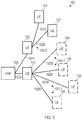
- the various UEs 131 - 135 are assigned to different sets 151 - 153. Each set is associated with a different relay 121 - 123; i.e., communication between the UEs 131 - 135 assigned to different sets 151 - 153 and the access point node 120 employs different relaying channels 192 (not shown in FIG. 3 ).
- FIG. 3 This is illustrated in FIG. 3 where UEs 131, 132 communicate with the access point node 120 via the relaying channel 192-2 and the relay 122; while the UEs 133 - 136 communicate with the access point node 120 via the relaying channel 192-1 and the relay 121.
- Orthogonal resources may correspond to at least one of the following: resources residing on different carrier frequencies; and / or resources residing on the same carrier frequency, but being frequency divided; and / or resources being time divided; and / or resources being differently coded to be distinguishable by corresponding decoding.
- the orthogonal resources 261-263 are provided on the same carrier frequency, but are time and frequency divided as they use different time-frequency resource allocation 210.. By providing the resources 261-263 orthogonal to each other, interference between the various relaying channels 192-1, 192-2 is mitigated.
- the time-frequency resource allocations 210 can, e.g., correspond to resource blocks or resource elements according to the 3GPP LTE protocol.
- a further effect that may be achieved by the techniques described herein is to mitigate cell load, i.e., traffic load imposed on the access point node 120.
- This can be achieved by distributing the UEs 131 - 136 to connect to the access point node 120 via various relaying channels 192, 192-1, 192-2.
- the respective relays 121 - 123 may aggregate data and / or buffer data in order to reduce the number of messages communicated to the access point node 120.
- the respective relays 121 - 123 may process data in order to relief the access point node 120 from at least some processing 120 tasks.
- the reoccurring resources 261-263 are prospectively allocated by the eNB 130 to the different UEs 131 - 136 assigned to the different sets 151 - 153. This means that for a certain future time period the resources 261-263 are persistent; e.g., the reoccurring resources 261 - 263 may be semi-persistent in that they have a limited lifetime and expire by the end of the limited lifetime.
- the given UE 131 - 136 can readily transmit the data on the available resources and, in particular, does not need to send a dedicated scheduling request and wait for receiving a dedicated scheduling grant first.
- each UE 131 - 136 only has a comparably small amount of data to transmit, e.g., in the order of 0.5 MB or less.
- the shared reoccurring resources are not blocked long for transmission of each individual UE 131 - 136.
- bandwidth usage can benefit from schemes of providing shared resources.
- reoccurring resources 261 - 263 can be allocated on a data channel 251 of the radio link 200 and/or can be allocated on a control channel 252 of the radio link 200.
- the reoccurring resources 261 - 263 are allocated on a control channel 252.
- the control channel 252 is a random access control channel 252 that is reserved for attach messages of UEs 131 - 136 that are connecting to the cellular network 100, i.e., for connection setup.
- the reoccurring resources 261 - 263 associated with different sets 151 - 153 comprise a larger or smaller number of time-frequency resource allocations 210, are scheduled more often/less frequently, and / or in different frequency bands, etc.
- the reoccurring resources 261 - 263 can be generally scheduled with a fixed periodicity or having variable time intervals in-between.
- the reoccurring resources 261 - 263 can be broken down in UL reoccurring resources 261-1 and DL reoccurring resources 261-2, cf. FIG. 4B .
- transmission by the access point node 120 is essentially muted; e.g., this can be implemented by transmitting "none" information, e.g., by utilizing almost blank subframes (ABS) according to the 3GPP LTE protocol and / or padding.
- ABS almost blank subframes
- the relay 121 is not transmitting any information to the access point 130.
- FIG. 5 is a signaling diagram illustrating aspects of signaling in between various entities 120, 121, 122, 130 of the cellular network 100, wherein the signaling provides scheduling of shared resources to various relaying channels 192.
- communication of higher-layer data and control signaling such as paging is executed on a direct channel 191 between the UE 130 and the access point node 120.
- the UE 130 is already attached to the cellular network 100.
- a capability request 702 is sent from the relay 121 to the access point node 120 via the direct channel 191-1 between the relay 121 and the access point node 120.
- the capability request 702 may be sent upon network registration, i.e., during an Attach procedure during which the relay 121 attaches to the cellular network 100.
- relay functionality may be selectively enabled by a user of a UE implementing the relay functionality of the relay 121; in such a scenario, it would be possible that the capability request 702 is sent in response to the user activating the relay functionality.
- the capability request 702 is sent employing a unicast transmission on an uplink control channel section of the direct channel 191-1; likewise, the capability response 703 is sent employing a unicast transmission on a DL control channel section of the direct channel 191-1.
- the direct channel 191-1 in between the relay 121 and the access point node 124 for control signaling related to establishing the relaying channel 192-1 between the UE 130 and the access point node 120 via the relay 121.
- the direct channel 191-1 in between the relay 121 and the access point node 120 for communication of higher-layer data of the relay 121 itself; in particular, in the scenario where the relay functionality of the relay 121 is implemented by a UE having D2D functionality, higher-layer data originating at the UE 121 itself may be transmitted on a data channel section of the direct channel 191-1.
- the capability request may include an indicator indicating the relay 121, e.g., the international mobile subscriber identification (IMSI).
- IMSI international mobile subscriber identification
- the capability request 702 - implicitly or explicitly - indicates the capability of the relay 121 to establish the relaying channel 192-1.
- the relay 121 itself may be as UE which has the additional functionality of establishing the relaying channel 192-1 via the D2D communication.
- security credentials may be provided to the access point node 120 such that the access point node 120 may judge whether communication via the relaying channel 192-1 and the relay 121 would potentially cause a security risk. Such and further consideration can be taken into account by the access point node 120 when authorizing the relay 121 to establish the relaying channel 192-1 by means of a capability response 703.
- a further relay 122 is present; a capability negotiation corresponding to the capability request 702 and the capability response 703 may be executed in between the further relay 122 and the access point node 120 (not shown in FIG. 5 ).
- a capability negotiation comparable to 702, 703 may be executed between the access point node 120 and the UE 130 (not shown in FIG. 5 ).
- the UE 130 may be configured to negotiate with the access point node 120 its capability of communicate on a relaying channel 191-1, 191-2.
- This capability negotiation may allow to identify that the UE 130 has the capability of communicating via a relaying channel 191-1, 191-2.
- Technical capabilities and specifications of the UE 130 and / or security aspects may be considered in said capability negotiation.
- the capability negotiation may employ a control channel section of the direct channel 191. E.g., the capability negotiation may be part of an Attach procedure of the UE 130 to the network 100.
- the relays 121, 122 mimic the access point node 121 behavior such that the UE 130 is not aware that it is communicating via a relaying channel. Then, legacy functionality of the UE 130 may be used for communicating via the relaying channel 191-1, 191-2.
- the UE 130 detects presence of the relay 121 and the further relay 122.
- the relay 121 and the further relay 122 could be configured to broadcast a configuration message indicating the capability of the respective relay 121, 122 to establish the relaying channel (not shown in FIG. 5 ).
- the UE 130 via the direct channel 191, sends a connection request 704 to the access point node 120.
- the connection request 704 prompts the access point node 120 to grant communication via at least one of the relaying channels 191-1 of the relays 121, 122.
- the access point 120 assigns the given UE 130 to either the first set 151 or the second set 152, or maintains the communication implemented via the direct channel 191.
- connection request 704 may be sent in response to the UE 130 selecting communication via at least one of the relaying channels 191-1 over communication via the direct channel 191. This may be in response to a channel quality of the frontend 192B being favorable in terms of required transmission power and / or error rates, etc.
- connection request 704 is sent via the direct channel 191
- a one or more connection requests are sent via the relays 121, 122.
- the relays 121, 122 identify the UE 130 that intends to transmit data.
- the respective UE(s) 121, 122 may then indicate this information to the access point node 120.
- connection request 704 may be sent as part of an Attach procedure of the UE 130 to the cellular network 100.
- the communication request 704 is sent via a legacy random-access channel.
- the connection request 704 include an indicator indicating the UE 130, e.g., the IMSI. Further, the connection request 704 indicates channel quality of the frontend 192B of the respective relaying channel 192-1, 192-2, e.g., in terms of the received signal strength indicator (RSSI) measured by the UE 130.
- RSSI received signal strength indicator
- Channel sensing techniques may be employed.
- connection request 704 indicates a property of the UE 130; e.g., the property may be at least one of the following: a MTC functionality of the UE 130; a traffic pattern of the UE 130; a feature capability of the UE 130; a QoS requirement of the UE 130; a category of the UE 130; a location of the UE 130 in the cellular network 100; a channel quality of the direct channel 191 between the UE 130 and the access point node 120; and a coverage requirement of the UE 130. All such properties may be taken into account when assigning the UE 130 to a given set 151-153 at 705 and / or when allocating the reoccurring resources 261-263 to the various sets 151-153.
- the coverage requirement of the UE 130 can correspond to whether the respective UE 130 is associated with normal coverage or different levels of enhanced coverage.
- Enhanced coverage may require an increased transmission power when communicating with the respective UE 130.
- the channel quality can correspond to radio-related parameters such as the RSSI or quality information of the radio link 200.
- a channel quality indicator can be taken into account.
- the location within the cellular network 100 as mentioned above can be specified e.g. on cell-level or sub-cell level. Thereby, it becomes possible to assign those UEs 130 - 136 to the same set 151 - 153 that are within the same location area.
- a category of the UE 130 can correspond to device description types or features of the UE 130 - 136.
- the UE 130 - 136 can be one of a mobile phone, a smartphone, a tablet, a personal digital assistant, a mobile music player, a smart watch, a wearable electronic equipment, a smart meter, a sensor, an actuator, and a mobile computer.
- the UE 130 may be classified as having Machine Type Communication functionality.
- all sensors may be assigned to a first set 151; while all actuators are assigned to a second set 152.
- Different types of UEs 130 - 136 can provide different types of data.
- the different types of data can correspond different services such as Voice-over-IP, best effort data, high-priority data, etc.
- different QoS requirements typically need to be fulfilled when transmitting the data.
- These QoS requirements associated with the type of data of a given UE 130 - 136 can be taken into account when assigning the UE 130 to a given set 151 - 153.
- a feature capability of the UE 130 can correspond to certain limitations and possibilities in types and classes of data to be transmitted. E.g., if certain UE 130 cannot transmit in a given frequency band, or if certain UE 130 only allow to transmit small data, such limitations of the capability should be taken into account when assigning the UE 130 to a given sets 151 - 153.
- the traffic pattern of the UE 130 can correspond to a periodicity or frequency of occurrence with which data to be transmitted is expected to occur, a size of individual data blocks to be transmitted, an overall size of data, peak times for data to be transmitted, etc.
- some UE 130 may require a constant stream of small chunks of data
- other UE 130 could require only seldom transmission of large chunks of data.
- a first UE 130 - 136 needs to transmit data at a comparably low, but constant data rate of, e.g., 20 kilobit per second
- a second UE 130 - 136 might require sending of a status report having a large file size of 50 MB, e.g., once per day at 12 pm.
- Such traffic patterns can be taken into account when assigning the UE 130 to a given sets 151 - 153.
- the channel quality of the frontend 192B of the respective relaying channel 192-1, 192-2 may be a property of particular interest when assigning the UE 130 to a given set 151 - 153.
- it may be required to pay particular attention to beneficial properties in terms of channel quality of the frontend 192B.
- time-frequency resource allocations 210 can be scheduled at a comparably high density on the radio link 200; by this, it is ensured that, after data arrives in a transmit buffer of the UE 121 - 125, the time until the next allocated time-frequency allocation 210 is comparably small.
- time-frequency resource allocations 210 can be scheduled at a comparably high density on the radio link 200; by this, it is ensured that, after data arrives in a transmit buffer of the UE 121 - 125, the time until the next allocated time-frequency allocation 210 is comparably small.
- the UE 130 is assigned to the set 151 associated with the relaying channel 192-1 via the relay 121. Because of this, the access point node 120 sends a scheduling grant 706 to the relay 121, the scheduling grant 706 indicating the reoccurring resources 261 associated with the set 151 and allocated by the access point node 120 at 705. In the scenario of FIG. 5 , the scheduling grant 706 is sent employing a unicast transmission on a DL control channel section of the direct channel 191-1.
- the access point node 120 sends the scheduling grant 708 via the direct channel 191 to the UE 130; this is to inform the UE 130 that it should employ the relaying channel 192-1 via the relay 121 to communicate with the access point node 120 and to rely on the allocated reoccurring resources indicated by the scheduling grant 708.
- the scheduling grant 708 is sent by the relay 121 upon receiving the scheduling grant 706.
- the access point node 120 sends a scheduling grant 709 to the relay 122, the scheduling grant 709 indicating the reoccurring resources 262 associated with the set 152 and allocated by the access point node 120 at 705.
- the scheduling grant 709 is sent employing a unicast transmission on a DL control channel section of the direct channel between the access point node 120 and the relay 122.
- the reoccurring resources 262 can be employed by further UEs (not shown in FIG. 5 ) that are assigned to the set 152 to communicate with the access point node 120 via the relaying channel 191-2 of the relay 122.
- the relaying channel 192-1 provides bidirectional communication, i.e., UL and DL functionality.
- the relaying channel 192-1 provides only uni-directional communication, i.e., either UL or DL functionality.
- the relaying channel 192-1 provides uni-directional communication in the form of UL functionality (DL functionality) it would be possible that the DL functionality (UL functionality) is maintained on the direct channel 191 between the UE 130 and the access point node 120.
- the effect of reducing power consumption by the UE 130 may be achieved even if the relaying channel 191-1 only provides uni-directional communication in the form of UL functionality; this is because in such a scenario the transmission power employed by the UE 130 may be reduced to the shorted radio signal path in between the UE 130 and the relay 121 if compared to the radio signal path between the UE 130 and the access point node 120 directly.
- the direct channel 191 between the UE 130 and the access point node 120 is maintained, 711.
- the direct channel 191 is operated in an idle mode.
- communication on the direct channel 191 may be restricted to sending and/or receiving of control data such as paging of the UE 130 by the access point node 120.
- control signaling from the UE 130 to the access point node 120 may be via the direct channel 191 in idle mode.
- Paging may refer to the access point node 120 being able to request a UE 130 to initiate a network connection.
- the UE 130 can keep its receiver and transmitter switched off to save battery, but at a paging event, which typically occurs at predetermined time intervals, the UE 130 turns on the receiver and receives the control data to determine if it is being paged or not.
- the UE 130 attempts to setup a connection with the access point node 120 via the direct channel 191.
- FIG. 6 a scenario is shown where the relaying channel 192-1 has already been established, 722 and is used for communicating between the access point node 120 and the UE 130; the direct channel 191 between the UE 130 and the access point node 120 is operated in the idle mode, 721.
- a connection status report 723 is sent by the UE 130 and received by the access point node 120; in the scenario FIG. 6 , the connection status report 723 is sent via the relaying channel 192-1; in other scenarios, it would be possible to alternatively or additionally send the connection status report 723 via the direct channel 191.
- connection status report may generally correspond to the connection request 704; it would be possible that the connection status report 723 further comprises an indicator indicating the relaying channel 192-1.
- the connection status report 723 includes a current value of the channel quality of the frontend 192B of the relaying channel 192-1.
- the access point node 120 and / or the UE 130 may monitor the channel quality of the frontend 192B of the relaying channel 192-1.
- a channel quality of the relaying channel 192-1 determined by the relay 121 and/or the access point node 120, e.g., by implementing corresponding techniques of channel sensing in one or two of the nodes 120, 121.
- the UE 130 may repeatedly report the channel quality of the frontend 192B of the relaying channel 192-1 to the access point node 120, e.g., via the relaying channel 192-1 and / or via the direct channel 191.
- a control channel section may be employed for said reporting.
- the UE 130 is reassigned to the set 152 which is associated with the relaying channel 192-2 via the relay 122.
- changes in the properties of the UE 130 as illustrated above may also lead to reassignment of the UE 132 another set 151 - 153; current values of the properties may be included in the status report 723.
- Corresponding control signaling 726, 727, 730 informs the relays 121, 122 and the UE 130 of the new assignment of the UE 130 to the set 152. Once the UE 130 has been newly assigned to the set 152, data is communicated via the relaying channel 192-2, 729.
- the direct channel 191 is maintained between the access point node 120 and the UE 130 and continuously operated in the idle mode, 728.
- FIG. 7 a signaling diagram is shown which illustrates aspects of maintaining the direct channel 191 in the idle mode in between the access point node 120 and the UE 130.
- 741 and 742 generally correspond to 721 and 722, respectively.
- the relay 121 determines that the quality of the front end 192B of the relaying channel 192-1 has severely degraded and the connection between the relay 121 and the UE 130 is lost. Via the direct channel 191-1, the relay 121 sends a respective control message 743 to the access point node 120.
- the access point node 120 informs the UE 130 by means of a connection release 745 that communication should be moved to the direct channel 191 and that the relaying channel 192-1 should not be employed for any further. Because of this, data and control signaling is then executed on the direct channel 191, 744. As such, the direct channel 191 is selected for communication instead of any relaying channel 192-1, 192-2.
- a fallback to the direct channel 191 can be implemented with low latency. This may be of particular use in scenarios where the relay 121 is itself a mobile device such as a UE which may move around different locations within the cellular network 100.
- scenarios have been illustrated where the logic for assigning the UEs 130 - 136 to the various sets 151 - 153 resides within the access point node 120.
- scenarios have been illustrated where the logic for allocating the reoccurring resources shared between the UEs 130 - 136 assigned to the various sets 151 - 153 resides within the access point node 120.
- this logic resides within a network node 119 of the core of the cellular network 100.
- this logic resides within the respective relays 121 - 123.
- FIG. 8 a scenario is illustrated where the logic for assigning the UEs 130 - 136 to the various sets 151 - 153 resides within the relays 121 - 123.
- 751 - 753 generally correspond to 701 - 703.
- the access point node 120 allocates resources to the various sets 151 - 153. Providing the logic to allocate the reoccurring resources at the access point node 120 allows to conveniently determine orthogonal reoccurring resources for the various sets 151 - 153, thereby allowing to mitigate interference between the reoccurring resources associated with the various relaying channels 192, 192-1, 192-2.
- the access point node 120 also sends a respective scheduling grant 755 indicating the reoccurring resources; the scheduling grant 755 in the scenario of FIG. 8 is broadcasted and thus receives by, both, the relays 121, 122. In alternative implementations, two scheduling grants could be sent separately in two unicast transmissions.
- the access point node 120 sends an assignment configuration message 756 to each one of the relays 121, 122, e.g., employing a broadcast channel of the radio link 120 or employing the respective unicast direct channels191-1 in between the access point node 120 and the relays 121, 122.
- the assignment configuration message 756 indicates set classification information which parameterizes assignment of UEs 130 - 136 to the various sets 151 - 153.
- the set classification information may parameterize properties as illustrated above with respect to the connection request 704.
- the set classification information may parameterize at least one element selected from the group comprising: a MTC functionality of the respective UEs 130 - 136; a QoS requirement of the respective UEs 130 - 136; a category of the respective UEs 130 -136; a location of the respective UEs 130 - 136 within the cellular network 100; a channel quality of the respective direct channel 191 between the respective UEs 130 - 136 and the access point node 120; a coverage requirement of the respective UEs 130 - 136; a channel quality of a frontend 192B of the respective relaying channel 192-1, 192-2 between the respective UEs 130 - 136 and the access point node 120.
- the UE 130 sends the connection request 757 directly to the relays 121, 122, e.g., employing a D2D channel of the radio link 200.
- the relays 121, 122 can autonomously judge whether the UE 130 has properties matching the specific set 151 - 153 associated with the corresponding relays 121, 122.
- the relay 121 judges that the UE 130 should be assigned to the set 151 associated with the relaying channel 192-1 and the relay 121; likewise, the relay 122 judges that the UE 130 should not be assigned to the set 152 associated with the relaying channel 192-2 and relay 122.
- the relay 121 can be configured to compare the property as reported by the given UE 130 against the set classification information; if the reported property of the given UE 130 fulfills (does not fulfill) the indicated property of the set classification information, the relay 121 may assign (may not assign) the given UE 130 to the respective set 151.
- the relays 121, 122 selectively assign the UE 130 to the corresponding sets 151, 152 depending on, both, the set classification information indicated by the assignment configuration message 756 and the properties of the UE 130 indicated by the connection request 757.
- the relay 121 sends a connection response including a scheduling grant 760 to the UE 130 to indicate to the UE 130 that it has been assigned to the set 151 and should start communicating via the relaying channel 192-1 and the relay 121 using the respective reoccurring resources 261 as allocated at 754. Because of this, the UE 130 and the access point node 120 start to communicate via the relaying channel 192-1, 761.
- the direct channel 191 is maintained and operated in idle mode, 762.
- the assignment configuration message 756 including the set classification information is provided by the access point node 120 to the relays 121, 122.
- set classification information is manually configured, e.g., by a user of the relays 121, 122.
- the access point node 120 sends the assignment configuration message 756, as the set classification information is locally provided at the relays 121, 122.
- the relays 121, 122 send an assignment report message (not shown in FIG. 8 ) to the access point node 120, the assignment report message including the manually configured set classification information, e.g., the UE 130 is manually assigned to the relay 122.
- each set 151 - 153 can comprise a plurality of UEs 130-136.
- those UEs 130-136 assigned to the same set 151 - 153 share the respective reoccurring resources 261 - 263.
- shared reoccurring resources 261-263 are employed, collision between data transmitted at the same time can occur; e.g., two UEs 130-136 assigned to the same set 151-153 may send data at the same time-frequency resource allocation 210.
- the eNB 130 and the respective UEs 130-136 execute a collision mitigation mechanism for data transmitted in the respective reoccurring resources 261 - 263.
- the collision mitigation mechanism can be selected from the group comprising: an Automatic Repeat Request scheme; Forward Error Correction; a carrier sense multiple access/collision detection; and / or orthogonal encoding.
- orthogonally encoding the respective data can allow to successfully transmit the data. However, if too many UEs 130-136 simultaneously send data in the same time-frequency resource allocation 210, orthogonally encoding may not be able to avoid interference and loss of data.
- the UEs 130-136 can be configured to wait for acknowledgment of the previously sent data.
- Acknowledgments may include at least one of positive acknowledgments and negative acknowledgments.
- the acknowledgments can be used by the UE 130-136 to determine if sending of the data was successful, i.e., if the data has been successfully transmitted.
- ACK positive acknowledgment
- NACK negative acknowledgment
- the UE can resend the data.
- a time-frequency resource allocation 210 for resending of the data can be randomly selected from the corresponding reoccurring resources 261-263.
- a random backoff mechanism can be used.
- the UE 130-136 can wait for a certain random backoff time before resending the data. If, a certain number of attempts of resending the data, transmission remains unsuccessful, the UE can stop resending the data, wait for a new scheduling grant, or utilize alternative resources - such as dedicated resources allocated in response to a scheduling request for sending of the data.
- FIG. 9 schematically illustrates a device that is configured to execute techniques as described herein.
- FIG. 9 is applicable to the node of the core network 119, the access point node 120 and the relays 121 - 123.
- the respective device 119 - 123 comprises a processor 902.
- the processor 902 can be a multicore processor. It is also possible to employ shared computing.
- the device 119 - 123 comprises a memory 903, e.g., a non-volatile memory.
- the memory 903 comprises can stroll instructions that can be executed by the processor 902. Executing the control instructions causes the processor 902 to perform the techniques as illustrated above.
- the control instructions can cause the processor 902 to create the sets 151 - 153, allocate the corresponding reoccurring resources 261 - 263, and/or select between the created sets 151 - 153 when assigning a given UE 130 - 136 to the various sets 151 - 153.
- the device 119 - 123 further comprises an interface 901. The interface can send and/or receive data, e.g., by transceiving on the radio link 200. Further, the device 119 - 123 comprises a human machine interface (HMI) 904.
- the HMI 904 can input instructions from a user and/or output instructions to a user.
- the relay functionality of the relays 121 - 123 is implemented by a UE, it would be possible that the user can selectively enable the relay functionality by inputting respective instructions via the HMI 904.
- Executing the control instructions stored in the memory 903 can, e.g., cause the processor 902 to execute a method as illustrated in the flowchart of FIG. 10 .
- the first reoccurring resources 261 are allocated to the first relaying channel 192-1, 1001.
- the second reoccurring resources 262 are allocated to the second relaying channel 192-2, 1002.
- Executing the control instructions stored in the memory 903 can, e.g., cause the processor 902 to execute a method as illustrated in the flowchart of FIG. 11 .
- a scheduling message is received which indicates reoccurring resources dedicated to the relaying channel 192, 192-1, 192-2, 1101.
- the reoccurring resources 261 - 263 being dedicated to the relaying channel 192, 192-1, 192-2 can correspond to the reoccurring resources 261 - 263 being orthogonal to further reoccurring resources dedicated to further relaying channel's 192, 192-1, 192-2.
- the relaying channel 192, 192-1, 192-2 is established and communication on the relaying channel 192, 192-1, 192-2 is relayed.
- the given one of the UEs 130 - 136 is selectively assigned to the respective set 151 - 153 associated with the reoccurring resources as indicated by the scheduling message of 1101.
- the additional relaying channel is in addition to a direct channel between the respective UE and the cellular network.
- the relaying channel is established by a UE implementing relaying functionality; as such, the UE implementing the relaying functionality may be seen as an access point node with comparably limited operation.
- the relaying channel it is possible to achieve a comparably high channel quality of the relaying channel; this is because the relaying channel may rely on shorter radio signal paths if compared to the direct channel.
- a transmit power may be reduced resulting in energy efficient operation of the UE.
- the battery lifetime of the UE may be prolonged.
- relaying channels are associated with different reoccurring resources that are orthogonal to each other. Thereby, interference in between various relaying channels can be mitigated.
- First layer of hierarchy Orthogonal resources are allocated to different relaying channels such that inter-channel interference is mitigated.
- Second layer of hierarchy UEs of single set share reoccurring resources; the UEs are assigned to the set based on properties that promise efficient utilization of the shared reoccurring resources; thus, intra-channel interference is mitigated.
- the different relaying channels/the different reoccurring resources are associated with different sets to which the UEs are assigned. Assignment of UEs to the sets can depend on various properties including, but not limited to: a traffic pattern of the respective UEs; a feature capability of the respective UEs; a QoS requirement of the respective UEs, etc. Thereby, it can be assured that within a given set the corresponding associated reoccurring resources are efficiently used by the assigned UEs.
- VVhile above various techniques have been described primarily with respect to the MTC technology and in the framework of the Internet of Things, it should be understood that such techniques may be readily applied to different types and kinds of cellular networks.
Landscapes
- Engineering & Computer Science (AREA)
- Computer Networks & Wireless Communication (AREA)
- Signal Processing (AREA)
- Quality & Reliability (AREA)
- Mobile Radio Communication Systems (AREA)
Claims (15)
- Nœud (119, 120) d'un réseau cellulaire (100), comportant :- une interface (901) configurée pour communiquer avec une pluralité de dispositifs (121-123, 130-136) de communication rattachés au réseau cellulaire (100) via une liaison radio (200),- au moins un processeur (902) configuré pour attribuer des premières ressources récurrentes (261-263) sur la liaison radio (200) du réseau cellulaire (100) à un premier canal (192, 192-1, 192-2) de relais, le premier canal (192, 192-1, 192-2) de relais se trouvant entre un nœud (120) de point d'accès du réseau cellulaire (100) et certains dispositifs de la pluralité de dispositifs (121-123, 130-136) de communication qui sont affectés à un premier ensemble (151-153),le ou les processeurs (902) étant en outre configurés pour attribuer des deuxièmes ressources récurrentes (261-263) sur la liaison radio (200) du réseau cellulaire (100) à un deuxième canal (192, 192-1, 192-2) de relais, le deuxième canal (192, 192-1, 192-2) de relais se trouvant entre le nœud (120) de point d'accès du réseau cellulaire (100) et certains dispositifs de la pluralité de dispositifs (121-123, 130-136) de communication qui sont affectés à un deuxième ensemble (151-153),
les premières ressources récurrentes (261-263) étant partagées entre les dispositifs (130-136) de communication affectés au premier ensemble (151-153), les deuxièmes ressources récurrentes (261-263) étant partagées entre les dispositifs (130-136) de communication affectés au deuxième ensemble (151-153), caractérisé en ce que
le ou les processeurs (902) sont configurés pour recevoir, via l'interface (901), un message de connexion, le message (704, 723, 743) de connexion indiquant un dispositif donné parmi la pluralité de dispositifs (121-123, 130-136) de communication,
le ou les processeurs (902) étant configurés pour affecter le dispositif donné parmi la pluralité de dispositifs (121-123, 130-136) de communication au premier ensemble (151-153) ou au deuxième ensemble (151-153) en réaction à la réception du message (704, 723, 743) de connexion. - Nœud (119, 120) selon la revendication 1,
le ou les processeurs (902) étant configurés pour envoyer, via l'interface (901) à un premier nœud (121-123) de relais, un premier message (706, 708, 759) d'ordonnancement, le premier nœud (121-123) de relais étant configuré pour établir le premier canal (192, 192-1, 192-2) de relais, le premier message (706, 708, 759) d'ordonnancement indiquant les premières ressources récurrentes (261-263),
le ou les processeurs (902) étant configurés pour envoyer, via l'interface (901) à un deuxième nœud (121-123) de relais, un deuxième message (706, 708, 759) d'ordonnancement, le deuxième nœud (121-123) de relais étant configuré pour établir le deuxième canal (192, 192-1, 192-2) de relais, le deuxième message (706, 708, 759) d'ordonnancement indiquant les deuxièmes ressources récurrentes (261-263). - Nœud (119, 120) selon la revendication 2,
le ou les processeurs (902) étant configurés pour recevoir, via l'interface (901) en provenance du premier nœud (121-123) de relais, un premier message (702, 752) de capacité, le premier message (702, 752) de capacité indiquant une capacité du premier nœud (121-123) de relais à établir le premier canal (192, 192-1, 192-2) de relais,
le ou les processeurs (902) étant configurés pour recevoir, via l'interface (901) en provenance du deuxième nœud (121-123) de relais, un deuxième message (702, 752) de capacité, le deuxième message (702, 752) de capacité indiquant une capacité du deuxième nœud (121-123) de relais à établir le deuxième canal (192, 192-1, 192-2) de relais,
ladite attribution des premières ressources récurrentes (261-263) intervenant en réaction à la réception du premier message (702, 752) de capacité,
ladite attribution des deuxièmes ressources récurrentes (261-263) intervenant en réaction à la réception du deuxième message (702, 752) de capacité. - Nœud (119, 120) selon les revendications 2 ou 3,
le nœud (119, 120) étant le nœud (120) de point d'accès configuré pour émettre et recevoir sans fil sur la liaison radio (200),
au moins un nœud parmi le premier nœud (121-123) de relais et le deuxième nœud (121-123) de relais étant un dispositif de communication sélectionné parmi la pluralité de dispositifs (121-123, 130-136) de communication,
le ou les processeurs (902) étant configurés pour communiquer, via l'interface (901) avec le ou les nœuds parmi le premier nœud (121-123) de relais et le deuxième nœud (121-123) de relais, sur un canal direct (191-1) de la liaison radio (200). - Nœud (119, 120) selon l'une quelconque des revendications précédentes,
le nœud (119, 120) étant le nœud (120) de point d'accès du réseau cellulaire (100) configuré pour émettre et recevoir sans fil sur la liaison radio (200),
le ou les processeurs (902) étant configurés pour communiquer, via l'interface (901), avec les dispositifs (130-136) de communication affectés au premier ensemble (151-153), sur le premier canal (192, 192-1, 192-2) de relais,
le ou les processeurs (902) étant configurés pour communiquer, via l'interface (901), avec les dispositifs (130-136) de communication affectés au deuxième ensemble (151-153), sur le deuxième canal (192, 192-1, 192-2) de relais. - Nœud (119, 120) selon l'une quelconque des revendications précédentes,
le ou les processeurs (902) étant configurés pour communiquer, via l'interface (901), avec les dispositifs (130-136) de communication affectés au premier ensemble (151-153) et avec les dispositifs (130-136) de communication affectés au deuxième ensemble (151-153), sur des canaux directs (191) respectifs de la liaison radio (200) dans un mode de repos. - Nœud (119, 120) selon l'une quelconque des revendications précédentes,
le message (704, 723, 743) de connexion indiquant en outre une qualité de canal d'un équipement frontal (192B) d'au moins un canal parmi le premier canal (192, 192-1, 192-2) de relais et le deuxième canal (192, 192-1, 192-2) de relais,
le ou les processeurs (902) étant configurés pour affecter le dispositif donné parmi la pluralité de dispositifs (121-123, 130-136) de communication au premier ensemble (151-153) ou au deuxième ensemble (151-153) suivant la qualité de canal indiquée du canal ou des canaux parmi le premier canal (192, 192-1, 192-2) de relais et le deuxième canal (192, 192-1, 192-2) de relais,
le ou les processeurs (902) étant configurés pour surveiller la qualité de canal de l'équipement frontal (192B) du canal ou des canaux parmi le premier canal (192, 192-1, 192-2) de relais et le deuxième canal (192, 192-1, 192-2) de relais en réaction à l'attribution des premières ressources récurrentes (261-263) et des deuxièmes ressources récurrentes (261-263). - Nœud (119, 120) selon l'une quelconque des revendications précédentes,
le message (704, 723, 743) de connexion indiquant en outre au moins un élément sélectionné dans le groupe comprenant :- une fonctionnalité de communication de type machine du dispositif donné parmi la pluralité de dispositifs (121-123, 130-136) de communication ;- un schéma de trafic du dispositif donné parmi la pluralité de dispositifs (121-123, 130-136) de communication ;- une capacité caractéristique du dispositif donné parmi la pluralité de dispositifs (121-123, 130-136) de communication ;- une exigence de qualité de service du dispositif donné parmi la pluralité de dispositifs (121-123, 130-136) de communication ;- une catégorie du dispositif donné parmi la pluralité de dispositifs (121-123, 130-136) de communication ;- un emplacement, au sein le réseau cellulaire (100), du dispositif donné parmi la pluralité de dispositifs (121-123, 130-136) de communication ;- une qualité de canal d'un canal direct (191) entre le dispositif donné parmi la pluralité de dispositifs (121-123, 130-136) de communication et le nœud (120) de point d'accès du réseau cellulaire (100) ;- une exigence de couverture du dispositif donné parmi la pluralité de dispositifs (121-123, 130-136) de communication,le ou les processeurs (902) étant configurés pour affecter le dispositif donné parmi la pluralité de dispositifs (121-123, 130-136) de communication au premier ensemble (151-153) ou au deuxième ensemble (151-153) suivant l'élément ou les éléments indiqués. - Nœud (119, 120) selon l'une quelconque des revendications précédentes,
le ou les processeurs (902) étant configurés pour établir des informations de classification d'ensemble pour le premier ensemble et le deuxième ensemble,
les informations de classification d'ensemble paramétrant l'affectation de dispositifs de communication au premier ensemble (151-153) et au deuxième ensemble (151-153),
le ou les processeurs (902) étant configurés pour envoyer, via l'interface (901) au premier nœud (121-123) de relais et au deuxième nœud (121-123) de relais, au moins un message (756) de configuration d'affectation indiquant les informations de classification d'ensemble. - Nœud (119, 120) selon l'une quelconque des revendications précédentes,
les premières ressources récurrentes (261-263) étant orthogonales aux deuxièmes ressources récurrentes (261-263) . - Procédé, comportant les étapes consistant à :- attribuer, à un premier canal (192, 192-1, 192-2) de relais, des premières ressources récurrentes (261-263) sur une liaison radio (200) d'un réseau cellulaire (100), le premier canal (192, 192-1, 192-2) de relais se trouvant entre un nœud (120) de point d'accès du réseau cellulaire (100) et certains dispositifs d'une pluralité de dispositifs (121-123, 130-136) de communication rattachés au réseau cellulaire (100) via la liaison radio (200),- attribuer, à un deuxième canal (192, 192-1, 192-2) de relais, des deuxièmes ressources récurrentes (261-263) sur la liaison radio (200) du réseau cellulaire (100), le deuxième canal (192, 192-1, 192-2) de relais se trouvant entre le nœud (120) de point d'accès du réseau cellulaire (100) et certains dispositifs de la pluralité de dispositifs (121-123, 130-136) de communication rattachés au réseau cellulaire (100) via la liaison radio (200), les premières ressources récurrentes (261-263) étant partagées entre les dispositifs (130-136) de communication affectés à un premier ensemble (151-153), les deuxièmes ressources récurrentes (261-263) étant partagées entre les dispositifs (130-136) de communication affectés à un deuxième ensemble (151-153), caractérisé par les étapes consistant à
recevoir un message de connexion, le message (704, 723, 743) de connexion indiquant un dispositif donné parmi la pluralité de dispositifs (121-123, 130-136) de communication, et
affecter le dispositif donné parmi la pluralité de dispositifs (121-123, 130-136) de communication au premier ensemble (151-153) ou au deuxième ensemble (151-153) en réaction à la réception du message (704, 723, 743) de connexion. - Nœud (121-123) de relais d'un réseau cellulaire (100), comportant :- une interface (901) configurée pour communiquer avec un nœud (119, 120) d'un réseau cellulaire (100) via une liaison radio (200) du réseau cellulaire (100) et configurée en outre pour communiquer avec certains dispositifs d'une pluralité de dispositifs (121-123, 130-136) de communication rattachés au réseau cellulaire (100) via la liaison radio (200),- au moins un processeur (902) configuré pour recevoir, via l'interface (901) en provenance du nœud (119, 120), un message (706, 708, 759) d'ordonnancement, le message (706, 708, 759) d'ordonnancement indiquant des ressources récurrentes (261-263) attribuées à un canal (192, 192-1, 192-2) de relais de la liaison radio (200), le canal (192, 192-1, 192-2) de relais se trouvant entre un nœud (120) de point d'accès du réseau cellulaire (100) et les dispositifs considérés de la pluralité de dispositifs de communication qui sont affectés à un ensemble (151-153), les ressources récurrentes (261-263) étant partagées entre les dispositifs (130-136) de communication affectés à l'ensemble (151-153),
le ou les processeurs (902) étant configurés pour établir le canal (192, 192-1, 192-2) de relais et pour relayer une communication entre le nœud (120) de point d'accès du réseau cellulaire (100) et les dispositifs (130-136) de communication affectés à l'ensemble (151-153) sur le canal (192, 192-1, 192-2) de relais, caractérisé en ce que
le ou les processeurs (902) sont configurés pour recevoir, via l'interface (901), en provenance d'un dispositif donné parmi la pluralité de dispositifs (121-123, 130-136) de communication, un message (757) de connexion indiquant le dispositif donné parmi la pluralité de dispositifs (121-123, 130-136) de communication. - Nœud (121-123) de relais selon la revendication 12, le nœud (121-123) de relais étant configuré pour envoyer, via l'interface (901) au nœud (119, 120), un message (702, 752) de capacité, le message (702, 752) de capacité indiquant une capacité du nœud (121-123) de relais à établir le canal (192, 192-1, 192-2) de relais.
- Nœud (121-123) de relais selon les revendications 12 ou 13,
le nœud (121-123) de relais étant un dispositif de communication sélectionné parmi la pluralité de dispositifs (121-123, 130-136) de communication,
le ou les processeurs (902) étant configurés pour communiquer, via l'interface (901), avec le nœud (120) de point d'accès du réseau cellulaire (100), sur un canal direct (191-1) de la liaison radio (200). - Procédé, comportant les étapes consistant à :- recevoir, en provenance d'un nœud (119, 120) d'un réseau cellulaire (100), un message (706, 708, 759) d'ordonnancement, le message (706, 708, 759) d'ordonnancement indiquant des ressources récurrentes (261-263) attribuées à un canal (192, 192-1, 192-2) de relais de la liaison radio (200), le canal (192, 192-1, 192-2) de relais se trouvant entre un nœud (120) de point d'accès du réseau cellulaire (100) et certains dispositifs d'une pluralité de dispositifs (121-123, 130-136) de communication rattachés au réseau cellulaire (100) via une liaison radio (200) et affectés à un ensemble (151-153), les ressources récurrentes (261-263) étant partagées entre les dispositifs (130-136) de communication affectés à l'ensemble (151-153),- établir le canal (192, 192-1, 192-2) de relais,- relayer, sur le canal (192, 192-1, 192-2) de relais, une communication entre le nœud (120) de point d'accès du réseau cellulaire (100) et les dispositifs (130-136) de communication affectés à l'ensemble (151-153), caractérisé par l'étape consistant àrecevoir, en provenance d'un dispositif donné parmi la pluralité de dispositifs (121-123, 130-136) de communication, un message (757) de connexion indiquant le dispositif donné parmi la pluralité de dispositifs (121-123, 130-136) de communication.
Applications Claiming Priority (3)
| Application Number | Priority Date | Filing Date | Title |
|---|---|---|---|
| PCT/EP2015/056375 WO2016150495A1 (fr) | 2015-03-25 | 2015-03-25 | Relais dans des réseaux cellulaires |
| PCT/EP2015/056553 WO2016150513A1 (fr) | 2015-03-26 | 2015-03-26 | Ordonnancement dans des réseaux cellulaires |
| PCT/EP2015/070348 WO2016150525A1 (fr) | 2015-03-25 | 2015-09-07 | Ordonnancement dans des réseaux cellulaires |
Publications (2)
| Publication Number | Publication Date |
|---|---|
| EP3275258A1 EP3275258A1 (fr) | 2018-01-31 |
| EP3275258B1 true EP3275258B1 (fr) | 2020-05-20 |
Family
ID=56977779
Family Applications (1)
| Application Number | Title | Priority Date | Filing Date |
|---|---|---|---|
| EP15759798.0A Active EP3275258B1 (fr) | 2015-03-25 | 2015-09-07 | Ordonnancement dans des réseaux cellulaires |
Country Status (4)
| Country | Link |
|---|---|
| US (1) | US10461837B2 (fr) |
| EP (1) | EP3275258B1 (fr) |
| CN (1) | CN107432025B (fr) |
| WO (1) | WO2016150525A1 (fr) |
Families Citing this family (7)
| Publication number | Priority date | Publication date | Assignee | Title |
|---|---|---|---|---|
| EP4709026A2 (fr) * | 2016-05-12 | 2026-03-11 | InterDigital Patent Holdings, Inc. | Connexion à des réseaux centraux mobiles virtualisés |
| WO2018061759A1 (fr) * | 2016-09-30 | 2018-04-05 | 京セラ株式会社 | Procédé de commande de communication |
| EP3310098A1 (fr) | 2016-10-17 | 2018-04-18 | Gemalto M2M GmbH | Procédé de communication sans fil de dispositif à dispositif |
| US10098138B1 (en) * | 2016-12-06 | 2018-10-09 | Sprint Spectrum L.P. | Systems and methods for configuring a scheduler |
| WO2020221521A1 (fr) * | 2019-04-30 | 2020-11-05 | Sony Corporation | Procédés pour permettre une signalisation de référence de faisceau, dispositifs sans fil et noeuds de réseau |
| US11765723B2 (en) * | 2019-10-11 | 2023-09-19 | Qualcomm Incorporated | Scheduling via wireless communication relay |
| CN116389406B (zh) * | 2023-06-05 | 2023-08-15 | 上海星思半导体有限责任公司 | Ue id的确定方法、ue id范围的发送方法、装置及处理器 |
Family Cites Families (45)
| Publication number | Priority date | Publication date | Assignee | Title |
|---|---|---|---|---|
| US6931255B2 (en) | 1998-04-29 | 2005-08-16 | Telefonaktiebolaget L M Ericsson (Publ) | Mobile terminal with a text-to-speech converter |
| FI107772B (fi) | 1998-12-16 | 2001-09-28 | Nokia Networks Oy | Menetelmä ja järjestelmä tiedonsiirron palvelunlaadun rajoittamiseksi |
| DE10038256B4 (de) | 2000-08-04 | 2007-03-22 | Siemens Ag | Zugriffsverfahren in Kommunikationssystemen mit unterschiedlichen Leistungsklassen und Kommunikationssystem |
| US8880709B2 (en) | 2001-09-12 | 2014-11-04 | Ericsson Television Inc. | Method and system for scheduled streaming of best effort data |
| JP3865212B2 (ja) | 2001-10-17 | 2007-01-10 | 株式会社エヌ・ティ・ティ・ドコモ | 送信電力設定方法、移動通信システム及び基地局 |
| US7286553B2 (en) | 2001-12-04 | 2007-10-23 | Murata Kikai Kabushiki Kaisha | Communication device and method for controlling communication device |
| US7352714B2 (en) | 2002-09-24 | 2008-04-01 | Lucent Technologies Inc. | Methods and apparatuses for allocating time slots to half duplex wireless mobile stations |
| US7420950B2 (en) | 2004-04-05 | 2008-09-02 | Dspg Ltd. | Multiplex communication with slotted retransmission on demand |
| US7477621B1 (en) | 2004-09-07 | 2009-01-13 | Marvell International Ltd. | System and method for estimating bandwidth requirements of and allocating bandwidth to communication devices operating in a network |
| TWI352550B (en) * | 2006-10-04 | 2011-11-11 | Ind Tech Res Inst | Wireless communication systems, methods, and data |
| JP4819129B2 (ja) | 2006-10-27 | 2011-11-24 | 三菱電機株式会社 | データ通信方法、通信システム及び移動端末 |
| WO2008115393A2 (fr) | 2007-03-15 | 2008-09-25 | Interdigital Technology Corporation | Attribution de ressources et signalisation pour programmation de groupes dans des communications sans fil |
| US9049670B2 (en) | 2007-06-01 | 2015-06-02 | Telefonaktiebolaget L M Ericsson (Publ) | Interference-improved uplink data rates for a group of mobile stations transmitting to a base station |
| US7957418B2 (en) | 2007-07-31 | 2011-06-07 | Research In Motion Limited | Data burst communication techniques for use in increasing data throughput to mobile communication devices |
| CN101785353B (zh) * | 2007-08-31 | 2013-04-24 | 上海贝尔股份有限公司 | 无线中继网络中的资源分配控制方法及装置 |
| US8509162B2 (en) * | 2008-02-13 | 2013-08-13 | Qualcomm Incorporated | System and method for scheduling over multiple hops |
| FI20085193A0 (fi) * | 2008-02-29 | 2008-02-29 | Nokia Siemens Networks Oy | Toistinsolmun yhteydenhallinta |
| EP2327272B1 (fr) * | 2008-07-17 | 2013-06-05 | Nokia Siemens Networks OY | Communications de dispositif à dispositif dans un système cellulaire |
| WO2010006650A1 (fr) | 2008-07-17 | 2010-01-21 | Nokia Siemens Networks Oy | Sélection de type de connexion dans un système de télécommunications cellulaires |
| KR101586864B1 (ko) * | 2008-08-01 | 2016-02-03 | 엘지전자 주식회사 | 중계기를 포함하는 무선통신 시스템에서 백홀링크 및 액세스링크를 위한 자원할당 방법 |
| EP2173054A1 (fr) | 2008-10-06 | 2010-04-07 | Thomson Licensing | Procédé pour la réception et la transmission de blocs de données |
| US8335466B2 (en) * | 2008-12-19 | 2012-12-18 | Research In Motion Limited | System and method for resource allocation |
| KR101489516B1 (ko) * | 2009-01-22 | 2015-02-06 | 엘지전자 주식회사 | 중계기가 도입된 무선통신 시스템에서 백홀신호 전송방법 |
| WO2011078631A2 (fr) | 2009-12-27 | 2011-06-30 | 엘지전자 주식회사 | Procédé et appareil pour commander la puissance de transmission de liaison montante dans un système de communication sans fil à porteuses multiples |
| JP5553107B2 (ja) | 2010-03-12 | 2014-07-16 | 富士通株式会社 | 中継装置、中継装置制御方法及び無線通信システム |
| KR101646282B1 (ko) | 2010-03-29 | 2016-08-08 | 엘지전자 주식회사 | 무선 통신 시스템에서 머신형 통신 장치의 데이터 전송 방법 및 장치 |
| US20130163508A1 (en) * | 2010-09-03 | 2013-06-27 | Nokia Siemens Networks Oy | Relay Nodes in Multi-Operator Scenario |
| US8306573B2 (en) | 2010-12-05 | 2012-11-06 | Motorola Solutions, Inc. | Method and apparatus for increasing call capacity on a carrier |
| WO2012104644A1 (fr) | 2011-02-04 | 2012-08-09 | Wireless Technology Solutions Llc | Système de communication mobile, équipement d'infrastructure, et procédé utilisant un numéro d'identification court pour ordonnancer des ressources |
| GB2487907B (en) | 2011-02-04 | 2015-08-26 | Sca Ipla Holdings Inc | Telecommunications method and system |
| CN102695281B (zh) * | 2011-03-21 | 2015-05-27 | 中国移动通信集团公司 | 一种资源分配方法、装置、系统及相关设备 |
| CN103138869B (zh) * | 2011-11-22 | 2015-08-19 | 中国移动通信集团公司 | 信道状态信息参考信号的发送方法、基站及中继 |
| CN103220789B (zh) * | 2012-01-19 | 2016-08-03 | 中国移动通信集团公司 | 资源分配方法、用户调度方法及其装置、设备 |
| US9264912B2 (en) * | 2012-01-19 | 2016-02-16 | Telefonaktiebolaget L M Ericsson (Publ) | Fractional frequency re-use and beamforming in relay nodes of a heterogeneous network |
| CN103384406B (zh) * | 2012-05-03 | 2016-05-11 | 普天信息技术研究院有限公司 | 一种中继系统的调度方法 |
| US8989113B2 (en) | 2012-05-11 | 2015-03-24 | Blackberry Limited | Method and system for partitioning contention based resources in a wireless network |
| US9219541B2 (en) | 2012-06-13 | 2015-12-22 | All Purpose Networks LLC | Baseband data transmission and reception in an LTE wireless base station employing periodically scanning RF beam forming techniques |
| CN103841603B (zh) | 2012-11-20 | 2019-05-31 | 北京三星通信技术研究有限公司 | 上行分组调度的方法及设备 |
| US20140171062A1 (en) | 2012-12-19 | 2014-06-19 | Telefonaktiebolaget L M Ericsson (Publ) | Wireless Devices, Network Node and Methods for Handling Relay Assistance in a Wireless Communications Network |
| CN103916967B (zh) * | 2013-01-04 | 2017-11-21 | 中国移动通信集团公司 | 中继节点间的干扰协调方法和装置 |
| IL224926A0 (en) | 2013-02-26 | 2013-07-31 | Valdimir Yanover | A method and system for allocating resources in the @telecommunications@cellphone network |
| US20140321367A1 (en) | 2013-04-26 | 2014-10-30 | Sprint Communications Company L.P. | Wireless communication system with multiple device-to-device (d2d) communication configurations |
| EP2833694A3 (fr) | 2013-07-29 | 2015-04-01 | HTC Corporation | Procédé de découverte de relais et communication dans un système de communication sans fil |
| KR101982306B1 (ko) * | 2014-03-21 | 2019-05-24 | 후아웨이 테크놀러지 컴퍼니 리미티드 | 랜덤 액세스 응답 방법, 기지국, 및 단말기 |
| CN104010300B (zh) | 2014-06-09 | 2018-05-15 | 宇龙计算机通信科技(深圳)有限公司 | 数据传输方法 |
-
2015
- 2015-09-07 EP EP15759798.0A patent/EP3275258B1/fr active Active
- 2015-09-07 WO PCT/EP2015/070348 patent/WO2016150525A1/fr not_active Ceased
- 2015-09-07 CN CN201580077043.2A patent/CN107432025B/zh not_active Expired - Fee Related
-
2016
- 2016-02-04 US US15/015,950 patent/US10461837B2/en active Active
Non-Patent Citations (1)
| Title |
|---|
| None * |
Also Published As
| Publication number | Publication date |
|---|---|
| CN107432025A (zh) | 2017-12-01 |
| CN107432025B (zh) | 2021-09-17 |
| US10461837B2 (en) | 2019-10-29 |
| WO2016150525A1 (fr) | 2016-09-29 |
| US20160286567A1 (en) | 2016-09-29 |
| EP3275258A1 (fr) | 2018-01-31 |
Similar Documents
| Publication | Publication Date | Title |
|---|---|---|
| US11109403B2 (en) | Method and apparatus for scheduling uplink data in mobile communication system | |
| JP7741095B2 (ja) | Nr v2xにおけるリソースを予約する方法及び装置 | |
| US11546827B2 (en) | Method and device for changing wireless path in wireless communication system | |
| US11979859B2 (en) | Methods and systems for autonomous sidelink resource allocation | |
| US11140697B2 (en) | Technique for sidelink feedback transmissions | |
| EP3275258B1 (fr) | Ordonnancement dans des réseaux cellulaires | |
| JP6789302B2 (ja) | 通信方法、ネットワーク側装置、及び端末 | |
| EP3917260B1 (fr) | Procédé et appareil de planification de données de liaison montante dans un système de communication mobile | |
| CN116349355A (zh) | 用于在nr v2x中执行资源重新选择的方法和设备 | |
| KR20220037492A (ko) | 무선 통신 시스템에서 사이드링크 송신을 위한 방법 및 장치 | |
| US11805501B2 (en) | Resource allocation for carrier aggregation | |
| CN116368919A (zh) | 用于改进nr v2x中的资源分配的方法和装置 | |
| US20250016826A1 (en) | Sidelink unlicensed priorities for channel access and resource reservation | |
| JP7737546B2 (ja) | 無線通信システムにおける予約リソースの衝突に関連する情報を送受信するための方法及び装置 | |
| US20250330823A1 (en) | Method and apparatus for sidelink unlicensed resource allocation | |
| US10362594B2 (en) | Scheduling in cellular networks | |
| WO2022077453A1 (fr) | Procédé de communication et appareil de communication |
Legal Events
| Date | Code | Title | Description |
|---|---|---|---|
| STAA | Information on the status of an ep patent application or granted ep patent |
Free format text: STATUS: THE INTERNATIONAL PUBLICATION HAS BEEN MADE |
|
| PUAI | Public reference made under article 153(3) epc to a published international application that has entered the european phase |
Free format text: ORIGINAL CODE: 0009012 |
|
| STAA | Information on the status of an ep patent application or granted ep patent |
Free format text: STATUS: REQUEST FOR EXAMINATION WAS MADE |
|
| 17P | Request for examination filed |
Effective date: 20171012 |
|
| AK | Designated contracting states |
Kind code of ref document: A1 Designated state(s): AL AT BE BG CH CY CZ DE DK EE ES FI FR GB GR HR HU IE IS IT LI LT LU LV MC MK MT NL NO PL PT RO RS SE SI SK SM TR |
|
| AX | Request for extension of the european patent |
Extension state: BA ME |
|
| RIN1 | Information on inventor provided before grant (corrected) |
Inventor name: PRIYANTO, BASUKI Inventor name: ZANDER, OLOF Inventor name: LJUNG, RICKARD Inventor name: PLICANIC SAMUELSSON, VANJA |
|
| DAV | Request for validation of the european patent (deleted) | ||
| DAX | Request for extension of the european patent (deleted) | ||
| STAA | Information on the status of an ep patent application or granted ep patent |
Free format text: STATUS: EXAMINATION IS IN PROGRESS |
|
| 17Q | First examination report despatched |
Effective date: 20190410 |
|
| GRAP | Despatch of communication of intention to grant a patent |
Free format text: ORIGINAL CODE: EPIDOSNIGR1 |
|
| STAA | Information on the status of an ep patent application or granted ep patent |
Free format text: STATUS: GRANT OF PATENT IS INTENDED |
|
| INTG | Intention to grant announced |
Effective date: 20191213 |
|
| GRAS | Grant fee paid |
Free format text: ORIGINAL CODE: EPIDOSNIGR3 |
|
| GRAA | (expected) grant |
Free format text: ORIGINAL CODE: 0009210 |
|
| STAA | Information on the status of an ep patent application or granted ep patent |
Free format text: STATUS: THE PATENT HAS BEEN GRANTED |
|
| AK | Designated contracting states |
Kind code of ref document: B1 Designated state(s): AL AT BE BG CH CY CZ DE DK EE ES FI FR GB GR HR HU IE IS IT LI LT LU LV MC MK MT NL NO PL PT RO RS SE SI SK SM TR |
|
| RAP1 | Party data changed (applicant data changed or rights of an application transferred) |
Owner name: SONY CORPORATION |
|
| REG | Reference to a national code |
Ref country code: GB Ref legal event code: FG4D |
|
| REG | Reference to a national code |
Ref country code: CH Ref legal event code: EP |
|
| REG | Reference to a national code |
Ref country code: DE Ref legal event code: R096 Ref document number: 602015053068 Country of ref document: DE |
|
| REG | Reference to a national code |
Ref country code: AT Ref legal event code: REF Ref document number: 1273497 Country of ref document: AT Kind code of ref document: T Effective date: 20200615 |
|
| REG | Reference to a national code |
Ref country code: LT Ref legal event code: MG4D |
|
| REG | Reference to a national code |
Ref country code: NL Ref legal event code: MP Effective date: 20200520 |
|
| PG25 | Lapsed in a contracting state [announced via postgrant information from national office to epo] |
Ref country code: LT Free format text: LAPSE BECAUSE OF FAILURE TO SUBMIT A TRANSLATION OF THE DESCRIPTION OR TO PAY THE FEE WITHIN THE PRESCRIBED TIME-LIMIT Effective date: 20200520 Ref country code: FI Free format text: LAPSE BECAUSE OF FAILURE TO SUBMIT A TRANSLATION OF THE DESCRIPTION OR TO PAY THE FEE WITHIN THE PRESCRIBED TIME-LIMIT Effective date: 20200520 Ref country code: SE Free format text: LAPSE BECAUSE OF FAILURE TO SUBMIT A TRANSLATION OF THE DESCRIPTION OR TO PAY THE FEE WITHIN THE PRESCRIBED TIME-LIMIT Effective date: 20200520 Ref country code: NO Free format text: LAPSE BECAUSE OF FAILURE TO SUBMIT A TRANSLATION OF THE DESCRIPTION OR TO PAY THE FEE WITHIN THE PRESCRIBED TIME-LIMIT Effective date: 20200820 Ref country code: GR Free format text: LAPSE BECAUSE OF FAILURE TO SUBMIT A TRANSLATION OF THE DESCRIPTION OR TO PAY THE FEE WITHIN THE PRESCRIBED TIME-LIMIT Effective date: 20200821 Ref country code: IS Free format text: LAPSE BECAUSE OF FAILURE TO SUBMIT A TRANSLATION OF THE DESCRIPTION OR TO PAY THE FEE WITHIN THE PRESCRIBED TIME-LIMIT Effective date: 20200920 Ref country code: PT Free format text: LAPSE BECAUSE OF FAILURE TO SUBMIT A TRANSLATION OF THE DESCRIPTION OR TO PAY THE FEE WITHIN THE PRESCRIBED TIME-LIMIT Effective date: 20200921 |
|
| PG25 | Lapsed in a contracting state [announced via postgrant information from national office to epo] |
Ref country code: RS Free format text: LAPSE BECAUSE OF FAILURE TO SUBMIT A TRANSLATION OF THE DESCRIPTION OR TO PAY THE FEE WITHIN THE PRESCRIBED TIME-LIMIT Effective date: 20200520 Ref country code: LV Free format text: LAPSE BECAUSE OF FAILURE TO SUBMIT A TRANSLATION OF THE DESCRIPTION OR TO PAY THE FEE WITHIN THE PRESCRIBED TIME-LIMIT Effective date: 20200520 Ref country code: HR Free format text: LAPSE BECAUSE OF FAILURE TO SUBMIT A TRANSLATION OF THE DESCRIPTION OR TO PAY THE FEE WITHIN THE PRESCRIBED TIME-LIMIT Effective date: 20200520 Ref country code: BG Free format text: LAPSE BECAUSE OF FAILURE TO SUBMIT A TRANSLATION OF THE DESCRIPTION OR TO PAY THE FEE WITHIN THE PRESCRIBED TIME-LIMIT Effective date: 20200820 |
|
| REG | Reference to a national code |
Ref country code: AT Ref legal event code: MK05 Ref document number: 1273497 Country of ref document: AT Kind code of ref document: T Effective date: 20200520 |
|
| PG25 | Lapsed in a contracting state [announced via postgrant information from national office to epo] |
Ref country code: AL Free format text: LAPSE BECAUSE OF FAILURE TO SUBMIT A TRANSLATION OF THE DESCRIPTION OR TO PAY THE FEE WITHIN THE PRESCRIBED TIME-LIMIT Effective date: 20200520 Ref country code: NL Free format text: LAPSE BECAUSE OF FAILURE TO SUBMIT A TRANSLATION OF THE DESCRIPTION OR TO PAY THE FEE WITHIN THE PRESCRIBED TIME-LIMIT Effective date: 20200520 |
|
| PG25 | Lapsed in a contracting state [announced via postgrant information from national office to epo] |
Ref country code: CZ Free format text: LAPSE BECAUSE OF FAILURE TO SUBMIT A TRANSLATION OF THE DESCRIPTION OR TO PAY THE FEE WITHIN THE PRESCRIBED TIME-LIMIT Effective date: 20200520 Ref country code: ES Free format text: LAPSE BECAUSE OF FAILURE TO SUBMIT A TRANSLATION OF THE DESCRIPTION OR TO PAY THE FEE WITHIN THE PRESCRIBED TIME-LIMIT Effective date: 20200520 Ref country code: EE Free format text: LAPSE BECAUSE OF FAILURE TO SUBMIT A TRANSLATION OF THE DESCRIPTION OR TO PAY THE FEE WITHIN THE PRESCRIBED TIME-LIMIT Effective date: 20200520 Ref country code: SM Free format text: LAPSE BECAUSE OF FAILURE TO SUBMIT A TRANSLATION OF THE DESCRIPTION OR TO PAY THE FEE WITHIN THE PRESCRIBED TIME-LIMIT Effective date: 20200520 Ref country code: DK Free format text: LAPSE BECAUSE OF FAILURE TO SUBMIT A TRANSLATION OF THE DESCRIPTION OR TO PAY THE FEE WITHIN THE PRESCRIBED TIME-LIMIT Effective date: 20200520 Ref country code: IT Free format text: LAPSE BECAUSE OF FAILURE TO SUBMIT A TRANSLATION OF THE DESCRIPTION OR TO PAY THE FEE WITHIN THE PRESCRIBED TIME-LIMIT Effective date: 20200520 Ref country code: RO Free format text: LAPSE BECAUSE OF FAILURE TO SUBMIT A TRANSLATION OF THE DESCRIPTION OR TO PAY THE FEE WITHIN THE PRESCRIBED TIME-LIMIT Effective date: 20200520 Ref country code: AT Free format text: LAPSE BECAUSE OF FAILURE TO SUBMIT A TRANSLATION OF THE DESCRIPTION OR TO PAY THE FEE WITHIN THE PRESCRIBED TIME-LIMIT Effective date: 20200520 |
|
| REG | Reference to a national code |
Ref country code: DE Ref legal event code: R097 Ref document number: 602015053068 Country of ref document: DE |
|
| PG25 | Lapsed in a contracting state [announced via postgrant information from national office to epo] |
Ref country code: PL Free format text: LAPSE BECAUSE OF FAILURE TO SUBMIT A TRANSLATION OF THE DESCRIPTION OR TO PAY THE FEE WITHIN THE PRESCRIBED TIME-LIMIT Effective date: 20200520 Ref country code: SK Free format text: LAPSE BECAUSE OF FAILURE TO SUBMIT A TRANSLATION OF THE DESCRIPTION OR TO PAY THE FEE WITHIN THE PRESCRIBED TIME-LIMIT Effective date: 20200520 |
|
| PLBE | No opposition filed within time limit |
Free format text: ORIGINAL CODE: 0009261 |
|
| STAA | Information on the status of an ep patent application or granted ep patent |
Free format text: STATUS: NO OPPOSITION FILED WITHIN TIME LIMIT |
|
| 26N | No opposition filed |
Effective date: 20210223 |
|
| REG | Reference to a national code |
Ref country code: CH Ref legal event code: PL |
|
| PG25 | Lapsed in a contracting state [announced via postgrant information from national office to epo] |
Ref country code: SI Free format text: LAPSE BECAUSE OF FAILURE TO SUBMIT A TRANSLATION OF THE DESCRIPTION OR TO PAY THE FEE WITHIN THE PRESCRIBED TIME-LIMIT Effective date: 20200520 |
|
| REG | Reference to a national code |
Ref country code: BE Ref legal event code: MM Effective date: 20200930 |
|
| PG25 | Lapsed in a contracting state [announced via postgrant information from national office to epo] |
Ref country code: LU Free format text: LAPSE BECAUSE OF NON-PAYMENT OF DUE FEES Effective date: 20200907 |
|
| PG25 | Lapsed in a contracting state [announced via postgrant information from national office to epo] |
Ref country code: CH Free format text: LAPSE BECAUSE OF NON-PAYMENT OF DUE FEES Effective date: 20200930 Ref country code: BE Free format text: LAPSE BECAUSE OF NON-PAYMENT OF DUE FEES Effective date: 20200930 Ref country code: LI Free format text: LAPSE BECAUSE OF NON-PAYMENT OF DUE FEES Effective date: 20200930 Ref country code: IE Free format text: LAPSE BECAUSE OF NON-PAYMENT OF DUE FEES Effective date: 20200907 |
|
| PG25 | Lapsed in a contracting state [announced via postgrant information from national office to epo] |
Ref country code: TR Free format text: LAPSE BECAUSE OF FAILURE TO SUBMIT A TRANSLATION OF THE DESCRIPTION OR TO PAY THE FEE WITHIN THE PRESCRIBED TIME-LIMIT Effective date: 20200520 Ref country code: MT Free format text: LAPSE BECAUSE OF FAILURE TO SUBMIT A TRANSLATION OF THE DESCRIPTION OR TO PAY THE FEE WITHIN THE PRESCRIBED TIME-LIMIT Effective date: 20200520 Ref country code: CY Free format text: LAPSE BECAUSE OF FAILURE TO SUBMIT A TRANSLATION OF THE DESCRIPTION OR TO PAY THE FEE WITHIN THE PRESCRIBED TIME-LIMIT Effective date: 20200520 |
|
| PG25 | Lapsed in a contracting state [announced via postgrant information from national office to epo] |
Ref country code: MK Free format text: LAPSE BECAUSE OF FAILURE TO SUBMIT A TRANSLATION OF THE DESCRIPTION OR TO PAY THE FEE WITHIN THE PRESCRIBED TIME-LIMIT Effective date: 20200520 Ref country code: MC Free format text: LAPSE BECAUSE OF FAILURE TO SUBMIT A TRANSLATION OF THE DESCRIPTION OR TO PAY THE FEE WITHIN THE PRESCRIBED TIME-LIMIT Effective date: 20200520 |
|
| P01 | Opt-out of the competence of the unified patent court (upc) registered |
Effective date: 20230527 |
|
| PGFP | Annual fee paid to national office [announced via postgrant information from national office to epo] |
Ref country code: GB Payment date: 20230823 Year of fee payment: 9 |
|
| PGFP | Annual fee paid to national office [announced via postgrant information from national office to epo] |
Ref country code: FR Payment date: 20230822 Year of fee payment: 9 Ref country code: DE Payment date: 20230822 Year of fee payment: 9 |
|
| REG | Reference to a national code |
Ref country code: DE Ref legal event code: R119 Ref document number: 602015053068 Country of ref document: DE |
|
| GBPC | Gb: european patent ceased through non-payment of renewal fee |
Effective date: 20240907 |
|
| PG25 | Lapsed in a contracting state [announced via postgrant information from national office to epo] |
Ref country code: DE Free format text: LAPSE BECAUSE OF NON-PAYMENT OF DUE FEES Effective date: 20250401 |
|
| PG25 | Lapsed in a contracting state [announced via postgrant information from national office to epo] |
Ref country code: GB Free format text: LAPSE BECAUSE OF NON-PAYMENT OF DUE FEES Effective date: 20240907 |
|
| PG25 | Lapsed in a contracting state [announced via postgrant information from national office to epo] |
Ref country code: FR Free format text: LAPSE BECAUSE OF NON-PAYMENT OF DUE FEES Effective date: 20240930 |