EP3275609A1 - Installation et procédé d'usinage de pièces en bois, en matière synthétique et analogues - Google Patents
Installation et procédé d'usinage de pièces en bois, en matière synthétique et analogues Download PDFInfo
- Publication number
- EP3275609A1 EP3275609A1 EP17001266.0A EP17001266A EP3275609A1 EP 3275609 A1 EP3275609 A1 EP 3275609A1 EP 17001266 A EP17001266 A EP 17001266A EP 3275609 A1 EP3275609 A1 EP 3275609A1
- Authority
- EP
- European Patent Office
- Prior art keywords
- workpieces
- tables
- longitudinal
- processing
- tool
- Prior art date
- Legal status (The legal status is an assumption and is not a legal conclusion. Google has not performed a legal analysis and makes no representation as to the accuracy of the status listed.)
- Granted
Links
Images


Classifications
-
- B—PERFORMING OPERATIONS; TRANSPORTING
- B27—WORKING OR PRESERVING WOOD OR SIMILAR MATERIAL; NAILING OR STAPLING MACHINES IN GENERAL
- B27M—WORKING OF WOOD NOT PROVIDED FOR IN SUBCLASSES B27B - B27L; MANUFACTURE OF SPECIFIC WOODEN ARTICLES
- B27M1/00—Working of wood not provided for in subclasses B27B - B27L, e.g. by stretching
- B27M1/08—Working of wood not provided for in subclasses B27B - B27L, e.g. by stretching by multi-step processes
-
- B—PERFORMING OPERATIONS; TRANSPORTING
- B23—MACHINE TOOLS; METAL-WORKING NOT OTHERWISE PROVIDED FOR
- B23Q—DETAILS, COMPONENTS, OR ACCESSORIES FOR MACHINE TOOLS, e.g. ARRANGEMENTS FOR COPYING OR CONTROLLING; MACHINE TOOLS IN GENERAL CHARACTERISED BY THE CONSTRUCTION OF PARTICULAR DETAILS OR COMPONENTS; COMBINATIONS OR ASSOCIATIONS OF METAL-WORKING MACHINES, NOT DIRECTED TO A PARTICULAR RESULT
- B23Q1/00—Members which are comprised in the general build-up of a form of machine, particularly relatively large fixed members
- B23Q1/03—Stationary work or tool supports
- B23Q1/037—Stationary work or tool supports comprising series of support elements whose relative distance is adjustable
Definitions
- the invention relates to a system for processing workpieces made of wood, plastic and the like according to the preamble of claim 1 and a method for machining workpieces made of wood, plastic and the like according to the preamble of claim 10.
- Known systems are used for machining workpieces from which window and door frames or window sash are made.
- the workpieces are clamped in a feed unit such that the longitudinal side of the workpiece can be processed with the appropriate tool. If the one longitudinal side processed, the workpiece is transferred to a second feed unit so that the opposite longitudinal side of the workpieces can also be edited.
- the end machining of the workpieces takes place with a machining unit that moves in the Y direction while the feed unit is stationary.
- the relative movement between the tool and the feed unit is thus perpendicular to the X direction, which is relevant for the longitudinal processing of the workpieces.
- the invention has the object of providing the generic system and the generic method in such a way that even higher performance can be achieved.
- the two feed units each have at least two tables.
- the tables of each feed unit are adjustable relative to each other in the X direction. As a result, workpieces of different lengths can be optimally clamped in the two feed units.
- the tables of the two feed units are each provided with at least one clamping element. With the tables of the two feed units, two or more workpieces can be clamped so that they extend in the X direction.
- the tables of the two feed units are driven so far with the clamped workpieces in the X and Y directions to each other so far that the workpieces lie with their longitudinal sides facing each other.
- the workpieces in the two feed units are in this case aligned with each other so that their ends are approximately flush or at a height. This makes it possible to edit the two lying at the same height ends of the workpieces in each case in one operation.
- the tables of the feed units can be moved apart in the Y direction so that the workpieces machined at their ends are spaced from one another such that at least one longitudinal processing tool can be inserted between the workpieces. With him the mutually facing longitudinal sides of the workpieces can be edited.
- the tables of the two feed units are independently adjustable in the X and / or Y direction. Then can the tables and their clamping elements are positioned at the optimum position relative to the workpiece to be clamped and machined.
- the tables of the two feed units are arranged on carriages which can be moved in the X direction along guides.
- the tables can thus be moved over the carriages in the X direction.
- the carriages in turn, have guides in the Y direction, by means of which the tables can be moved transversely to the X direction in the Y direction.
- the system has at least one further feed unit, which is adjustable in the X direction. With this further feed unit, the partially processed workpieces can be taken over by the other two feed units.
- the further feed unit is movable along a further guide, which, seen in the X direction, is located between the guides of the two other feed units.
- the tables of the two other feed units are moved so far apart in the Y direction that the further feed unit can move between the separated tables of the other two feed units. Then, with the further feed unit, the partially machined workpieces can be simply transferred to the further feed unit.
- the further feed unit is provided with a clamping device with which the workpieces can be clamped.
- the clamping device of the further feed unit advantageously has collets, which are arranged in two rows, which extend in the X direction and face each other. With the two rows of collets, two or more workpieces can be clamped in the further feed unit.
- the further feed unit between the moved apart in the Y direction tables of the other two feed units is movable.
- the further feed unit can be moved between the separated tables.
- the guide for the further feed unit is located between the guides for the other two feed units.
- the feed units can be moved into the transfer position so that the workpieces can be reliably transferred from the other two feed units to the further feed unit.
- the processing units are provided on at least one portal, which extends at a distance over the guides for the feed units.
- the finished workpieces can be removed for further treatment of the system, it is advantageously provided at a delivery area with at least one delivery table on which the finished workpieces can be stored.
- the discharge table is advantageously arranged next to the travel path of the further feed unit, viewed in the X direction. Thereby, the further feed unit can be moved next to the discharge table, so that the workpieces can be easily delivered to the delivery table.
- the method according to the invention are at least two workpieces. stretched on tables of at least two feed units.
- the tables of each feed unit are adjustable relative to each other in the X direction.
- the tables are then moved together in the Y direction so that the Workpieces lie with their longitudinal sides facing each other.
- the workpieces are juxtaposed with their longitudinal sides first at one end and then processed at the other end in each case in one operation.
- the workpieces are in this case arranged to each other so that their end faces or ends are at least approximately at the same height. The end processing can therefore be carried out very easily and, above all, time-saving.
- the workpieces are moved so far apart after the end processing transversely to their adjacent longitudinal sides in the Y direction that these long sides can be worked longitudinally.
- both longitudinal sides of the workpieces can be machined simultaneously in at least one longitudinal machining tool according to an inventive method.
- the workpieces move on opposite sides of the tool in the X direction.
- the longitudinal processing tool is advantageously rotatably driven in such a way that the longitudinal sides of the opposing workpieces are machined in the opposite direction. Basically, however, a synchronous operation is possible.
- the workpieces are transferred to a further feed unit.
- the workpieces are clamped so that their other long sides are exposed, so that these other long sides can now be edited by a corresponding longitudinal processing tool.
- the workpieces do not change their position when transferring from the other two feed units to the further feed unit, the workpieces are constantly clamped during the transfer process.
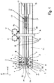
- Fig. 1 shows a schematic representation and a plan view of a plant for the longitudinal and transverse machining of elongate workpieces 1, 2. They have quadrangular cross-section and are processed on their longitudinal sides and at their ends in a manner to be described.
- the workpieces 1, 2 are fed to a task area 3 of the system and clamped on tables 4, 5, which are part of two feed units I, II and are each provided with at least one clamping device 6, 7 ( Fig. 2 ).
- the tables 4, 5 each sit on a carriage 8, 9, which in the X direction by means of guides 10 (FIG. Fig. 2 ) is displaceable.
- the guides 10 are shown schematically as extending in the X direction strips, which are provided at the top of a bed 11. In practice, the guides 10 may be known linear guides with rails and ball or roller guide carriage.
- each carriage 8, 9 of the respective table 4, 5 is displaceable perpendicular to the X direction in the Y direction.
- each carriage 8, 9 is provided with two guides 12, 13 extending parallel to each other in the Y-direction.
- the guides 10 extend over the entire length of the bed 11, so that the workpieces 1, 2 to be machined can be moved within the system in any desired position.
- three tables 4 and three tables 5 are provided by means of (not shown) drives can be moved independently of each other in the Y direction.
- the carriages 8, 9 associated with each table 4, 5 can be moved independently of each other by means of drives (not shown) on the guides 10 in the X-direction.
- the tables 4, 5 are moved together in the Y direction.
- the carriages 8, 9 can each be coupled and in each case moved via a common drive in the X direction.
- the slides 8 and 9 can be adjusted or moved relative to one another via further drives in a limited range in the X direction.
- a portal 14 is supported on the ground, which is provided with two tool units 15, 16 which are arranged on both sides of the portal 14 and are independently adjustable in the Y and Z directions. Notwithstanding the illustrated embodiment 14 further processing units may be provided on the fixed portal.
- the workpieces 1, 2 can be placed on top of a feed table 57 or directly on the tables 4, 5 and then clamped with the clamping devices 6, 7. But it is also possible to supply the workpieces 1, 2 in the X direction of the feed table 57 and the tables 4, 5.
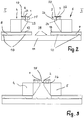
- Each table 4, 5 has as clamping device 6, 7 in each case a collet 19, 20 on ( Fig. 2 ). It is arranged on the table 4, 5 such that it partially overlaps the workpiece 1, 2 from one longitudinal side ( Fig. 2 ). How out Fig. 2 As can be seen, the collets 19, 20 of the mutually opposite tables 4, 5 are arranged so that they the workpieces 1, 2 facing away from each other Long sides 21, 22 from overlap.
- the workpieces 1, 2 lie flat on a bearing surface 23, 24 of the tables 4, 5.
- the workpieces 1, 2 are clamped in such a way that they project beyond the respective table 4, 5 and the collets 19, 20.
- a further feed unit V is provided with a table 27 which is movable in the X direction by means of guides 28.
- the guides 28 are located between the guides 10 of the tables 4, 5.
- the table 27 is provided with individual collets 29, which are each arranged in a row next to each other. The collet rows are in the Y direction at a distance next to each other.
- both feed units I, II each have three mutually opposite tables 4 and 5, which are independently movable in both the X and Y directions.
- the independent movability in the X direction makes it possible to reliably clamp workpieces 1, 2 of different lengths.
- all tables 4, 5 are used for clamping respectively.
- only one table 4, 5 is sufficient to firmly clamp the workpiece during machining by means of appropriate tools.
- the workpieces 1, 2 can be processed at their ends, they are clamped by means of the clamping devices 6, 7 of the tables 4, 5 in such a way that they project beyond the tables 4, 5 in the X-direction ( Fig. 1 ). Then leave the ends of the workpieces 1, 2 edit reliably by a corresponding transverse machining tool.
- the workpieces 1, 2 to be machined can be placed on the feed table 57, for example, by means of a gripper, which can be part of a loading portal, for example.
- a gripper which can be part of a loading portal, for example.
- the tables 4, 5 are automatically adjusted via a control in the required X position with respect to the workpieces 1, 2 to be machined, so that the workpieces 1, 2 with their ends on the tables 4, 5 survive.
- the data of the workpieces 1, 2 to be processed are determined prior to processing and communicated to the controller, which adjusts the tables 4, 5 in accordance with these parts data.
- the collets 19, 20 are located to the task of the workpieces 1, 2 on the tables 4, 5 in an upper release position.
- the workpieces are pushed by means of a ruler 58, 59 from the feed table 57 on the tables 4, 5. Due to the position of the tables 4, 5 in the Y direction and the travel of the ruler 58, 59, the clamping position of the workpieces 1, 2 is exactly defined. This is determined depending on the raw wood cross-section and the subsequent longitudinal profile so that the workpieces for processing this longitudinal profile in the Y direction on the collets 19, 20 and the tables 4, 5 protrude. Once the workpieces 1, 2 are supplied, the collets 19, 20 are adjusted in their clamping position down and made the clamping operation.
- the tables 4, 5 in the Y direction can have positionable stops, against which the workpieces 1, 2 are pushed by means of the rulers 58, 59, which then need not be positioned, but only drive back and forth.
- Such a design has the advantage that the workpieces are pushed 1.2 with a defined force against the stops, which are straight pressed before the clamping operation.
- the tables 4, 5 for receiving the workpieces 1, 2 in the Y direction along the guides 12, 13.
- the workpieces are advantageous in this case to a rigid stop, about which their position is fixed in the Y direction.
- the feed table 57 may be formed rake-shaped in a known manner, so that the tables 4, 5 can go with their support surfaces 23, 24 for receiving the workpieces 1, 2 in the gaps.
- the feed table 57 can be displaced or displaced during the transfer in the Y direction, while the workpiece 1, 2 remains supported on the rigid stop.
- the collets 19, 20 may be pivotable about a vertical axis (Z-direction), for example. Then the workpieces 1, 2 with the loading portal from the top directly on the tables 4, 5 are launched. Once the workpieces 1, 2 are placed, the collets 19, 20 are pivoted back into their clamping position and carried out the clamping operation. Further constructive embodiments, the collets 19, 20 away from the Zuglassweg of the workpieces 1, 2 for loading from above, are conceivable.
- the tables 4, 5 are moved by means of their slides 8, 9 in the X direction along the guides 10 in front of a machining spindle 30 of the tool unit 15.
- This can be done in a coupled manner, as described above, wherein the coupling of the slides 8, 9 can take place mechanically or by control technology by coupling the drives.
- On the machining spindle 30 sits the end working tool 31, with which the ends of the workpieces 1, 2 are processed.
- the tool unit 15 with the machining spindle 30 can be adjusted along the portal 14 in the Y and in the Z direction.
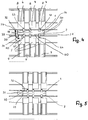
- the carriages 4, 5 are advantageously adjusted in the Y direction during their travel in the direction of the tool unit 15 in such a way that the workpieces 1, 2 lie against one another with their longitudinal sides 25, 26 facing one another.
- the end machining tool 31 (FIG. Fig. 4 ) the simultaneous processing of the ends of the abutting workpieces 1, 2.
- the workpieces 1, 2 are in this case aligned with each other so that their ends 32, 33; 34, 35 lie approximately flush.
- the tables 4, 5 can also be brought together before the process in the direction of the portal 14 or when reaching the end processing position in front of the portal 14.
- the ends 32, 33 of the workpieces 1, 2 are processed. Subsequently, by appropriate method of the tables 4, 5, the processing of the other ends 34, 35 made.
- the ends 32, 33; 34, 35 are milled in one operation at the same time without tool change, provided that the end profiles on the two sides are the same. Different end profiles require a tool change.
- the profiles of the adjacent ends 32, 33 and 34, 35 must be the same.
- the machining tool 31 rotates about its axis.
- Fig. 4 is shown with an arrow 36, the relative movement path between the end processing tool 31 and the workpieces 1,2 in the end processing.
- the rotating tool 31 can first dip slightly into the longitudinal side 60 of the workpiece 2 depending on subsequent longitudinal profiling.
- Fig. 5 shows the tool 31 in a position in which its axis of rotation 30 in the X direction in front of the ends 32, 33 of the workpieces 1, 2, ie in the frontal processing of the ends 32, 33, in which the feed units I, II and the workpieces 1, 2 fixed and the tool 31 moves in the Y-axis in the direction of arrow 36.
- the workpieces 1, 2 are in each case moved in the X direction with the tables 4, 5 in such a way that the tool unit 15 with its end-working tool 31 reaches the end faces 32, 33; 34, 35 of the workpieces 1, 2 can edit.
- the tool unit 15 for machining the end faces 32, 33 and the tool unit 16 for machining the end faces 34, 35 it is also possible to use the tool unit 15 for machining the end faces 32, 33 and the tool unit 16 for machining the end faces 34, 35.
- the tables 4 and 5 are moved apart in the opposite direction to one another in the Y direction, so that with a corresponding tool the longitudinal sides 25, 26 of the workpieces 1, 2 facing one another can be worked on lengthwise.
- the collets 19, 20 of the tables 4, 5 are, as exemplified by the 4 and 5 shows, so set that the long sides 25, 26 sufficient distance from the resting on the top of the workpieces 1, 2 collets 19, 20 have.
- the workpieces 1, 2 are clamped so that they project sufficiently far beyond the respective table 4, 5 or their bearing surfaces 23, 24 ( FIGS. 2 and 3 ).
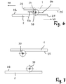
- the longitudinal processing of the workpieces 1, 2 takes place with a longitudinal processing tool 37 (FIG. Fig. 6 ). It is rotatable about a vertical axis 38 and part of the tool unit 15, 16, which is provided on the portal 14. In the tool units 15, 16 transverse and longitudinal processing tools can be changed, so that each tool unit 15, 16 can perform the transverse or longitudinal processing on the workpieces 1, 2.
- the workpieces 1, 2 are moved so far apart in the Y direction that the two longitudinal sides 25, 26 of the workpieces 1, 2 can be processed simultaneously with the longitudinal processing tool 37 ( Fig. 6 ).
- the longitudinal processing tool 37 is moved into its processing position with the tool unit 16 along the portal 14.
- the longitudinal machining tool rotating about its axis 38 generates the same profile on both longitudinal sides 25, 26 of the workpieces 1, 2.
- the workpieces 1, 2 in the X direction opposite to each other during the longitudinal processing process, which in Fig. 6 indicated by the arrows 39 and 40.
- the ends 32 and 35 of the workpieces 1, 2 are at the same height or at least approximately at the same height.
- Fig. 6 schematically two chip deflectors 56 are shown, which are diametrically opposed to each other and derive the resulting in the machining longitudinal processing chips.
- a profile is introduced into the longitudinal sides 25, 26 of the workpieces 1, 2, so that the longitudinal processing tool 37 is a corresponding profiling tool. If the same longitudinal profile on the workpieces 1, 2 is provided on the longitudinal sides 25, 26, the workpieces 1, 2, as can Fig. 6 emerges to be processed simultaneously with the longitudinal processing tool 37.
- a tool memory 41 is assigned to the tool unit ( Fig. 1 ), in which different tools are mounted, which can be simply loaded by means of a (not shown) gripping device in the tool unit 15, 16 when needed.
- Fig. 7 shows the case that the two workpieces 1, 2, for example, due to profile unevenness can not be processed simultaneously by one and the same longitudinal processing tool 37. Therefore, the workpieces 1, 2 are moved so far apart with the tables 4 and 5 in the Y direction that initially the longitudinal side 25 of the workpiece 1 can be processed and the workpiece 2 has sufficient distance from the longitudinal processing tool 37. If the longitudinal side 25 of the workpiece 1 is processed, the tool unit 16 is adjusted so far with the longitudinal processing tool 37 along the portal 14 in the Y direction that the longitudinal side 26 of the workpiece 2 can be processed. During the longitudinal processing, the respective workpiece 1, 2 is moved along the rotating longitudinal processing tool 37.
- the longitudinal sides 25, 26 of the two workpieces 1, 2 also simultaneously with each a longitudinal processing tool 37 are processed. If all end machining operations and the one-sided longitudinal machining on the respective workpiece 1, 2 are completed, the workpieces 1, 2 are transferred to the table 27 of the feed unit V.
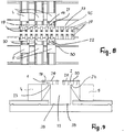
- the tables 4, 5 are moved so far apart in the Y direction that the table 27 can travel in the X direction along the guides 28 between the tables 4, 5 ( 8 and 9 ), or vice versa, the tables 4, 5 next to the table 27th
- the collets 29 of the table 27 are in the release position when the table 27 is moved between the tables 4, 5.
- the workpiece support of the table 29 is advantageously lowered slightly in a known manner.
- the table 27 is moved so far in the X direction that its collets 29, the workpieces 1, 2, which are clamped on the tables 4 and 5, can take over.
- Fig. 8 shows the transfer position of the table 27.
- the two workpieces 1, 2 are tensioned with the collets 29 in a known manner.
- the collets 19, 20 of the tables 4, 5 remain in the clamping position, so that the workpieces 1, 2 are always firmly clamped during the transfer.
- the collets 19, 20 of the tables 4, 5 are released and the supports 23, 24 of the tables 4, 5 lowered slightly. Subsequently, the table 27 is continued with the clamped workpieces 1, 2 in the X direction. If necessary, the tables 4, 5 can be previously moved so far away from the table 27 in the Y direction to the outside, that the table 27 with the clamped workpieces 1, 2 can be moved in the X direction.
- the collets 29 of the table 27 are adjusted so that they rest depending on the already processed longitudinal side 25, 26 of the workpieces 1, 2 on the top of the workpieces that the workpieces 1, 2 are reliably tensioned.
- the unprocessed longitudinal sides 21, 22 of the workpieces 1, 2 are exposed.
- the collets 29 have sufficient distance from these still unprocessed longitudinal sides 21, 22, so that these Long sides can be easily worked through a corresponding tool without any problems. If required and depending on the profile, the workpieces can also be clamped in a fold formed during the first longitudinal processing.
- the clamping jaws 29 of the table 27, which are not required for clamping the workpieces 1, 2, can be adjusted to a basic position.
- This basic position can be, for example, a lowered position in which the collets 29 can be adjusted so far down that their top is at least flush with the table top.
- the basic position can also be achieved in that the collets 29 are reset in the Y direction.
- the longitudinal processing of the workpieces 1, 2 takes place on their longitudinal sides 21, 22 with the aid of the longitudinal processing tool 37 of the tool unit 16 (FIG. Fig. 10 ).
- the longitudinal processing of the table 27 is moved along the guides 28 in the X direction, wherein the rotating about a vertical axis longitudinal processing tool 37, the longitudinal side 21, 22 processed.
- the workpieces 1, 2 are longitudinally processed without a tool change successively on their longitudinal sides 21, 22.
- the workpieces are machined over the entire length of these longitudinal sides 21, 22, preferably longitudinally profiled.
- the table 27 moves further in the X direction so far that the tool unit 16 can be adjusted along the portal 14 in the Y direction so that the longitudinal side 22 of the workpiece 2 can be processed. Again, the table 27 is moved during the longitudinal processing in the X direction relative to the tool unit 16.
- the tool unit 16 can also be designed so that the longitudinal processing tool 37 can be adjusted in the Z direction. Then it is possible, after completion of the longitudinal processing of the longitudinal side 21, the longitudinal processing tool 37 in the Z-direction upwards to adjust so far that it can be adjusted over the table 27 in the Y direction to the opposite longitudinal side 22. There, the longitudinal processing tool 37 is lowered again and now the longitudinal side 22 processed, the table 27 is moved in the required X direction.
- the tool unit 16 executes correspondingly controlled movements by moving away from the workpiece 1, 2 in the Y-direction. Due to the possibility of moving the tables 4, 5 in the Y direction, the same is also possible in the first longitudinal processing of the longitudinal sides 25, 26 on the feed units I, II in that the tables 4, 5 travel away from the longitudinal side of the workpiece 1, 2.
- the table 27 is moved to the delivery side in the X direction, at which the delivery tables 17, 18 are located.
- the finished workpieces 1, 2 are deposited on them after loosening the collets 29.
- portals 14 which are each associated with four tool memory 41. Both portals 14 are each provided with four tool units 15, 16.
- Fig. 11 is exemplified, as with the tool units 15 and their end processing tools 31 of the left portal 14, the dispensing area facing the ends of the workpieces 1, 2 and the tool units 15 and their end processing tools 31 of the right portal 14 from the dispensing area facing away from the workpieces. 1 , 2 are processed in the manner described. Since the tables 4, 5 are duplicated, the processing of these two ends of the workpieces 1, 2 takes place in parallel, whereby a high performance increase is achieved.
- the tables 4, 5 in the manner described in the Y direction so far apart moved that the facing longitudinal sides 25, 26 of the workpieces 1, 2 simultaneously with the corresponding longitudinal processing tools 37 can be edited.
- the tables 4, 5 are moved in the Y direction so far apart that the table 27 of the feed unit V can be moved between the tables 4 and 5 to in the described Way the machined on a longitudinal side workpieces 1, 2 of the tables 4, 5 record.
- the workpieces 1, 2 are clamped on the table 27 so that the other, unprocessed longitudinal side can now be processed by a corresponding longitudinal processing tool.
- the table 27 moves to the delivery area and transfers the finished workpieces 1, 2 to the delivery tables 17, 18.
- the feed unit II can be moved in the X direction to the position of the feed unit IV, which has previously moved away in the X direction.
- the partially machined workpiece 2 can be transferred from the feed unit II to the feed unit III in the manner described in order to machine the other longitudinal side of this workpiece 2.
- the system is characterized in that the feed units I, II, III, IV by individual Zangentician (Einzelzangentician) is formed, which are individually moved to different distances to each other and the workpieces 1, 2 can clamp at different positions.
- the feed units a Having a plurality of collets over their length, but arranged rigidly in the longitudinal direction and individually lower to achieve flexibility for clamping different machined workpieces are lowered below the support plane, there are some significant advantages: More flexible processing options on the long sides by even more flexible clamping, clamping with perfect end overhang on both sides for cross cutting and optimal clamping and transfer of short workpieces.
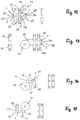
- Fig. 12 to 15 show how short parts can be processed effectively at their ends and on their long sides. Such short workpieces can be clamped easily and yet reliably, because the separate tables 4 and 5 are provided for the workpieces, each having a collet. Depending on the length of the workpieces 1, 2 can thus be used for clamping the short workpieces only part of the tables 4 and 5 respectively.
- Fig. 12 shows two short workpieces 1, 2 (short parts), which lie with their long sides 25, 26 to each other.
- two tables 4 and 5 are used, of which in Fig. 12 only the associated collets 19, 20 are shown.
- the third tables 4, 5 are moved so far away in the X direction that the ends 34, 35 to be machined can be machined with the end processing tool 31.
- Fig. 12 shows the starting position of the tool 31 for this screwing.
- Fig. 13 shows the tool 31 in the position immediately after screwing, from which the frontal machining is done only by the method of the tool 31 in the Y direction.
- the workpieces 1, 2 holding these tables 4, 5, as shown in the Fig. 1 to 11 has been described, moved apart in the Y direction, so that the longitudinal sides 25, 26 machined and then the table 27 between the tables 4, 5 can drive. Then the machined at their ends and one longitudinal side 25, 26 workpieces 1, 2 the table 27 passed, with which the workpieces can be clamped and processed on their other long sides 21, 22 in the manner described.
- FIGS. 14 and 15 show the possibility of working with the plant even those short workpieces that are not duplicated ( FIGS. 12 and 13 ) can be edited.
- the ends of only one workpiece are machined with the end working tool 31.
- the end working tool 31 For clamping this short workpiece 1 serve only the two left tables 4 and 5, of which in each case only the collet 19 and 20 is shown.
- the mutually opposite end-side tables 4 and 5 are arranged offset relative to one another in the X-direction so that the collets 19, 20 engage one another on the workpiece 1 in the X-direction.
- the collet 20 of the table 5 engages the in Fig.
- both collets 19, 20 are arranged so that with the end processing tool 31, the end 32 of the workpiece 1 can be processed.
- the end processing tool 31 performs the basis of the 4 and 5 described movement.
- the two collets 19, 20 engage from the opposite longitudinal sides 21, 25 from over the workpiece 1, that the collets 19, 20 in the process of the tables 4, 5 in the X direction can be moved past each other.
- the tables 4, 5 are adjusted in the X-direction so that the opposite end 34 of the workpiece 1 can be machined with the end-working tool 31.
- This Umspannvorgang takes place in such a way that the workpiece 1 is always clamped, so that its position is unchanged.
- This transfer operation can for example be done so that first the table 4 is moved so far to the left with its collet 19 in the X direction that the collet 19 biases the workpiece 1 in the region of the machined end 32.
- the workpiece 1 is held clamped by the collet 20 of the opposite table 5. Once the workpiece 1 is tightened with the collet 19 in the new position, the collet 20 is released and the table 5 so far back in the X direction to the left that the end processing tool 31 can edit the unprocessed end 34 in the manner described.
- Fig. 15 is indicated by a dashed line 42 by way of example an end profile, which has been generated with the end processing tool 31.
- the two other tables 4, 5 are driven away so that they do not interfere with the end machining of the workpiece 1.
- each only one workpiece can be processed at its ends, these workpieces are handed over to the table 27 after the end processing and one-sided longitudinal processing one by one. Since it has a plurality of collets 29 on both longitudinal sides extending in the X direction, a plurality of short workpieces can be clamped simultaneously on opposite longitudinal sides of the table 27 on the table 27. Then, in the manner described, these mutually opposite short workpieces can be processed in one operation, as is clear from the Fig. 6 to 10 has been described.
- the tables 4, 5, 27 are designed so that the tensioned workpieces 1, 2 with their underside on the flat bearing surfaces 23, 24 (FIG. Fig. 2 ) are tensioned lying with the collets 19, 20, 29.
- the collets themselves can be adjusted in a suitable and known manner from the clamping position to the release position. For example, it is possible, the collets around vertical axes 43, 44, 45 ( Fig. 4 and 8th ) to pivot.
- the collets 19, 20, 29 are advantageously designed as a one-armed lever, which, seen in the Z direction, have a rectangular outline.
- the pivot axes 43 to 45 are located at one end of the collets 19, 20, 29.
- the pivot axes 43 to 45 are adjustable for the clamping operation in the Z direction.
- the collets 19, 20, 29 can be, for example, by 90 ° or 180 ° from that shown in the drawings Swivel clamping position into the release position.
- the clamped workpieces 1, 2 in a simple manner from above on the support surfaces 23, 24 of the tables 4, 5, 27 hang up.
- the collets 19, 20, 29 form adjustable only in the Z direction. Then the collets 19, 20, 29 are in the rest position at a sufficiently large distance from the support surfaces 23, 24 of the tables 4, 5, 27, so that the workpieces to be machined easily in the X or Y direction on the tables can be hung up.
- the collets 29 of the table 27 may also be designed so that they can be adjusted so far in the Z direction down that the top of the collets 29 is at least flush with the support surface of the table 27. Then stand on the support surface of the table 27 only those collets 29, which are involved in the clamping process.
- a tool store 41 is provided, in which the corresponding tools for the end and longitudinal processing of the workpieces 1, 2 are deposited.
- the tools and gripping devices can be used, which are known per se and therefore not described in detail.
- Fig. 16 shows an example of a tool memory 41, which is characterized in that it can store a large number of tools 54 in a compact design. Of them, only the outlines are shown in FIG.
- the tool storage 41 has an annular base 46, on the outside of which storage locations 47 for the tools 54 are provided.
- the memory locations, 47 are provided with tong-shaped receptacles 48, in which the tools 54 are used and in which they are held in a known manner. So that the tools 54 can be easily and reliably stored in the storage space 47 and taken out of the storage space, the tools 54 are advantageously provided with a gripper groove into which the gripper of a changing device engages.
- the base body 46 surrounds two mutually perpendicular, mutually crossing webs 49, 50, which are connected with their ends to the inside of the base body 46.
- the base body 46 and the webs 49, 50 may be integrally formed with each other.
- the webs 49, 50 define together with the base body 46 receiving spaces 51, in which there are more memory locations 52, 53 for tools 54.
- the memory locations 52 are located within the respective receiving space 51 on the inside of the main body 46.
- the memory locations 53 are provided in the region of the intersection point of the diametrical webs 49, 50.
- the receiving spaces 51 are each formed so that the internal tools 54 can be easily switched on and replaced.
- the tool storage 41 is rotatable about its central axis 55, so that in a simple manner, the desired tool 54 can be brought into the gripping area of the gripper changing device.
- the tool storage 41 is controlled rotated in the desired position, so that the tool change can be made quickly.
- tools 54 are preferably used, which have small diameter.
- Such tools 54 are, for example, drills or end mills or milling tools with a small diameter.
Landscapes
- Engineering & Computer Science (AREA)
- Life Sciences & Earth Sciences (AREA)
- Mechanical Engineering (AREA)
- Wood Science & Technology (AREA)
- Forests & Forestry (AREA)
- Jigs For Machine Tools (AREA)
- Turning (AREA)
- Multi-Process Working Machines And Systems (AREA)
Applications Claiming Priority (1)
| Application Number | Priority Date | Filing Date | Title |
|---|---|---|---|
| DE102016009430.3A DE102016009430A1 (de) | 2016-07-29 | 2016-07-29 | Anlage und Verfahren zum Bearbeiten von Werkstücken aus Holz, Kunststoff und dergleichen |
Publications (2)
| Publication Number | Publication Date |
|---|---|
| EP3275609A1 true EP3275609A1 (fr) | 2018-01-31 |
| EP3275609B1 EP3275609B1 (fr) | 2024-04-03 |
Family
ID=59520712
Family Applications (1)
| Application Number | Title | Priority Date | Filing Date |
|---|---|---|---|
| EP17001266.0A Active EP3275609B1 (fr) | 2016-07-29 | 2017-07-25 | Installation et procédé d'usinage de pièces en bois, en matière synthétique et analogues |
Country Status (2)
| Country | Link |
|---|---|
| EP (1) | EP3275609B1 (fr) |
| DE (1) | DE102016009430A1 (fr) |
Families Citing this family (2)
| Publication number | Priority date | Publication date | Assignee | Title |
|---|---|---|---|---|
| IT201800009677A1 (it) | 2018-10-22 | 2020-04-22 | Working Process Srl | Centro di lavoro perfezionato, ad alta precisione e produttivita’, per la lavorazione di pezzi in legno. |
| DE102019003613A1 (de) * | 2019-05-21 | 2020-11-26 | Michael Weinig Ag | Verfahren zur Bearbeitung von Werkstücken aus Holz, Kunststoff und dergleichen |
Citations (5)
| Publication number | Priority date | Publication date | Assignee | Title |
|---|---|---|---|---|
| JPS55157417A (en) * | 1979-05-22 | 1980-12-08 | Toshiba Corp | Method, jig and tool for chamfering workpiece |
| EP1055485A2 (fr) * | 1999-05-07 | 2000-11-29 | Bacci Paolino Di Giuseppe Bacci Di Agostino Bacci | Machine-outil pour l'usinage d'objets de forme allongée et symétrique tels que d'éléments de construction pour chaises, meubles et autres éléments analogues |
| US20090308217A1 (en) * | 2008-06-17 | 2009-12-17 | Sony Corporation | Cutting apparatus |
| DE102010037547A1 (de) * | 2010-09-15 | 2012-03-15 | Klaus Hofmann | Spannsystem |
| EP2708312A1 (fr) * | 2012-06-15 | 2014-03-19 | Yamazaki Mazak Corporation | Centre d'usinage |
Family Cites Families (5)
| Publication number | Priority date | Publication date | Assignee | Title |
|---|---|---|---|---|
| DE19752685A1 (de) * | 1997-11-28 | 1999-07-01 | Ima Maschinenfabriken Klessmann Gmbh | Maschine zum Bearbeiten von Fensterrahmen-Holmen |
| ITBO20010643A1 (it) * | 2001-10-19 | 2003-04-19 | Impresa 2000 Di Sacchi Paride | Metodo e macchina per la lavorazione di componenti di legno o simili |
| DE102004027888B4 (de) * | 2004-05-27 | 2007-01-04 | Michael Weinig Ag | Vorschubeinheit für eine Maschine zum Bearbeiten von Werkstücken aus Holz, Kunststoff oder dergleichen sowie Verfahren zum Bearbeiten solcher Werkstücke |
| ITFI20060170A1 (it) * | 2006-07-05 | 2008-01-06 | Paolino Bacci Srl | Centro di lavoro con sistema di posizionamento degli organi di bloccaggio dei pezzi |
| ITPD20110007A1 (it) * | 2011-01-14 | 2012-07-15 | Working Process S R L | Centro di lavoro a sviluppo verticale |
-
2016
- 2016-07-29 DE DE102016009430.3A patent/DE102016009430A1/de not_active Withdrawn
-
2017
- 2017-07-25 EP EP17001266.0A patent/EP3275609B1/fr active Active
Patent Citations (5)
| Publication number | Priority date | Publication date | Assignee | Title |
|---|---|---|---|---|
| JPS55157417A (en) * | 1979-05-22 | 1980-12-08 | Toshiba Corp | Method, jig and tool for chamfering workpiece |
| EP1055485A2 (fr) * | 1999-05-07 | 2000-11-29 | Bacci Paolino Di Giuseppe Bacci Di Agostino Bacci | Machine-outil pour l'usinage d'objets de forme allongée et symétrique tels que d'éléments de construction pour chaises, meubles et autres éléments analogues |
| US20090308217A1 (en) * | 2008-06-17 | 2009-12-17 | Sony Corporation | Cutting apparatus |
| DE102010037547A1 (de) * | 2010-09-15 | 2012-03-15 | Klaus Hofmann | Spannsystem |
| EP2708312A1 (fr) * | 2012-06-15 | 2014-03-19 | Yamazaki Mazak Corporation | Centre d'usinage |
Also Published As
| Publication number | Publication date |
|---|---|
| DE102016009430A1 (de) | 2018-02-01 |
| EP3275609B1 (fr) | 2024-04-03 |
Similar Documents
| Publication | Publication Date | Title |
|---|---|---|
| EP1281491B1 (fr) | Dispositif et procédé pour travailler des pièces à usiner en bois, plastique ou similaires | |
| EP3197639B1 (fr) | Dispositif d'usinage | |
| EP3639971B1 (fr) | Procédé de traitement des pièces longues en bois, en matière plastique et analogue, ainsi que machine permettant de mettre en oeuvre ledit procédé | |
| EP4054791B1 (fr) | Cellule de fabrication pourvue d'un porte-outil | |
| EP3535092B1 (fr) | Machine de pierrage avec une pluralité de postes de travail | |
| EP4054792B1 (fr) | Cellule de fabrication pourvue d'au moins deux robots d'usinage | |
| EP0922547B1 (fr) | Dispositif pour la fabrication de châssis de fenêtres | |
| DE202017003923U1 (de) | Bearbeitungszentrum für Metallprofile | |
| EP0967038B1 (fr) | Dispositif d' usinage de pièces par enlèvement de matière | |
| EP1600254B1 (fr) | Unité d'avance pour machine à usiner des pièces et méthode pour usiner ces pièces | |
| EP2165811A2 (fr) | Machine et procédé de traitement de pièces usinées en bois, en matière synthétique et analogue | |
| DE102019007764B4 (de) | Werkstückwagen sowie Werkzeugmaschine und Fertigungszelle mit derartigem Werkstückwagen | |
| EP1688227B1 (fr) | Procédé de fonctionnement d'une machine à usiner le bois et machine à usiner le bois | |
| EP1651381B1 (fr) | Machine-outil avec systeme de fixation des deux cotes | |
| DE102017121393A1 (de) | Bearbeitungszentrum mit numerischer Steuerung | |
| EP3275609B1 (fr) | Installation et procédé d'usinage de pièces en bois, en matière synthétique et analogues | |
| EP3873297B1 (fr) | Procédé de fabrication de brosses et machine de fabrication de brosses | |
| DE102019003613A1 (de) | Verfahren zur Bearbeitung von Werkstücken aus Holz, Kunststoff und dergleichen | |
| WO2021204417A1 (fr) | Dispositif de serrage pour pièces | |
| DE19721521C2 (de) | Numerisch gesteuerte Zapfenschneidmaschine | |
| EP2792627B1 (fr) | Dispositif d'amarrage | |
| DE102011102793B3 (de) | Verfahren zur Bearbeitung der Stirnseiten von Werkstücken aus Holz, Kunststoff und dergleichen | |
| DE102020002322A1 (de) | Anlage zur Bearbeitung von Werkstücken aus Holz, Kunststoff, Aluminium und dergleichen sowie Verfahren zur Übergabe von Werkstücken zwischen einer ersten und einer zweiten Spanneinrichtung | |
| DE102013103284A1 (de) | Docking-System |
Legal Events
| Date | Code | Title | Description |
|---|---|---|---|
| PUAI | Public reference made under article 153(3) epc to a published international application that has entered the european phase |
Free format text: ORIGINAL CODE: 0009012 |
|
| STAA | Information on the status of an ep patent application or granted ep patent |
Free format text: STATUS: THE APPLICATION HAS BEEN PUBLISHED |
|
| AK | Designated contracting states |
Kind code of ref document: A1 Designated state(s): AL AT BE BG CH CY CZ DE DK EE ES FI FR GB GR HR HU IE IS IT LI LT LU LV MC MK MT NL NO PL PT RO RS SE SI SK SM TR |
|
| AX | Request for extension of the european patent |
Extension state: BA ME |
|
| STAA | Information on the status of an ep patent application or granted ep patent |
Free format text: STATUS: REQUEST FOR EXAMINATION WAS MADE |
|
| 17P | Request for examination filed |
Effective date: 20180731 |
|
| RBV | Designated contracting states (corrected) |
Designated state(s): AL AT BE BG CH CY CZ DE DK EE ES FI FR GB GR HR HU IE IS IT LI LT LU LV MC MK MT NL NO PL PT RO RS SE SI SK SM TR |
|
| STAA | Information on the status of an ep patent application or granted ep patent |
Free format text: STATUS: EXAMINATION IS IN PROGRESS |
|
| 17Q | First examination report despatched |
Effective date: 20191212 |
|
| GRAP | Despatch of communication of intention to grant a patent |
Free format text: ORIGINAL CODE: EPIDOSNIGR1 |
|
| STAA | Information on the status of an ep patent application or granted ep patent |
Free format text: STATUS: GRANT OF PATENT IS INTENDED |
|
| INTG | Intention to grant announced |
Effective date: 20231031 |
|
| GRAS | Grant fee paid |
Free format text: ORIGINAL CODE: EPIDOSNIGR3 |
|
| GRAA | (expected) grant |
Free format text: ORIGINAL CODE: 0009210 |
|
| STAA | Information on the status of an ep patent application or granted ep patent |
Free format text: STATUS: THE PATENT HAS BEEN GRANTED |
|
| AK | Designated contracting states |
Kind code of ref document: B1 Designated state(s): AL AT BE BG CH CY CZ DE DK EE ES FI FR GB GR HR HU IE IS IT LI LT LU LV MC MK MT NL NO PL PT RO RS SE SI SK SM TR |
|
| REG | Reference to a national code |
Ref country code: GB Ref legal event code: FG4D Free format text: NOT ENGLISH |
|
| REG | Reference to a national code |
Ref country code: CH Ref legal event code: EP |
|
| REG | Reference to a national code |
Ref country code: DE Ref legal event code: R096 Ref document number: 502017015975 Country of ref document: DE |
|
| REG | Reference to a national code |
Ref country code: IE Ref legal event code: FG4D Free format text: LANGUAGE OF EP DOCUMENT: GERMAN |
|
| REG | Reference to a national code |
Ref country code: LT Ref legal event code: MG9D |
|
| REG | Reference to a national code |
Ref country code: NL Ref legal event code: FP |
|
| PG25 | Lapsed in a contracting state [announced via postgrant information from national office to epo] |
Ref country code: IS Free format text: LAPSE BECAUSE OF FAILURE TO SUBMIT A TRANSLATION OF THE DESCRIPTION OR TO PAY THE FEE WITHIN THE PRESCRIBED TIME-LIMIT Effective date: 20240803 |
|
| PG25 | Lapsed in a contracting state [announced via postgrant information from national office to epo] |
Ref country code: BG Free format text: LAPSE BECAUSE OF FAILURE TO SUBMIT A TRANSLATION OF THE DESCRIPTION OR TO PAY THE FEE WITHIN THE PRESCRIBED TIME-LIMIT Effective date: 20240403 |
|
| PG25 | Lapsed in a contracting state [announced via postgrant information from national office to epo] |
Ref country code: HR Free format text: LAPSE BECAUSE OF FAILURE TO SUBMIT A TRANSLATION OF THE DESCRIPTION OR TO PAY THE FEE WITHIN THE PRESCRIBED TIME-LIMIT Effective date: 20240403 Ref country code: FI Free format text: LAPSE BECAUSE OF FAILURE TO SUBMIT A TRANSLATION OF THE DESCRIPTION OR TO PAY THE FEE WITHIN THE PRESCRIBED TIME-LIMIT Effective date: 20240403 |
|
| PG25 | Lapsed in a contracting state [announced via postgrant information from national office to epo] |
Ref country code: GR Free format text: LAPSE BECAUSE OF FAILURE TO SUBMIT A TRANSLATION OF THE DESCRIPTION OR TO PAY THE FEE WITHIN THE PRESCRIBED TIME-LIMIT Effective date: 20240704 |
|
| PG25 | Lapsed in a contracting state [announced via postgrant information from national office to epo] |
Ref country code: PT Free format text: LAPSE BECAUSE OF FAILURE TO SUBMIT A TRANSLATION OF THE DESCRIPTION OR TO PAY THE FEE WITHIN THE PRESCRIBED TIME-LIMIT Effective date: 20240805 |
|
| PG25 | Lapsed in a contracting state [announced via postgrant information from national office to epo] |
Ref country code: ES Free format text: LAPSE BECAUSE OF FAILURE TO SUBMIT A TRANSLATION OF THE DESCRIPTION OR TO PAY THE FEE WITHIN THE PRESCRIBED TIME-LIMIT Effective date: 20240403 |
|
| PG25 | Lapsed in a contracting state [announced via postgrant information from national office to epo] |
Ref country code: CZ Free format text: LAPSE BECAUSE OF FAILURE TO SUBMIT A TRANSLATION OF THE DESCRIPTION OR TO PAY THE FEE WITHIN THE PRESCRIBED TIME-LIMIT Effective date: 20240403 |
|
| PG25 | Lapsed in a contracting state [announced via postgrant information from national office to epo] |
Ref country code: PL Free format text: LAPSE BECAUSE OF FAILURE TO SUBMIT A TRANSLATION OF THE DESCRIPTION OR TO PAY THE FEE WITHIN THE PRESCRIBED TIME-LIMIT Effective date: 20240403 |
|
| PG25 | Lapsed in a contracting state [announced via postgrant information from national office to epo] |
Ref country code: LV Free format text: LAPSE BECAUSE OF FAILURE TO SUBMIT A TRANSLATION OF THE DESCRIPTION OR TO PAY THE FEE WITHIN THE PRESCRIBED TIME-LIMIT Effective date: 20240403 |
|
| PG25 | Lapsed in a contracting state [announced via postgrant information from national office to epo] |
Ref country code: PT Free format text: LAPSE BECAUSE OF FAILURE TO SUBMIT A TRANSLATION OF THE DESCRIPTION OR TO PAY THE FEE WITHIN THE PRESCRIBED TIME-LIMIT Effective date: 20240805 Ref country code: PL Free format text: LAPSE BECAUSE OF FAILURE TO SUBMIT A TRANSLATION OF THE DESCRIPTION OR TO PAY THE FEE WITHIN THE PRESCRIBED TIME-LIMIT Effective date: 20240403 Ref country code: NO Free format text: LAPSE BECAUSE OF FAILURE TO SUBMIT A TRANSLATION OF THE DESCRIPTION OR TO PAY THE FEE WITHIN THE PRESCRIBED TIME-LIMIT Effective date: 20240703 Ref country code: LV Free format text: LAPSE BECAUSE OF FAILURE TO SUBMIT A TRANSLATION OF THE DESCRIPTION OR TO PAY THE FEE WITHIN THE PRESCRIBED TIME-LIMIT Effective date: 20240403 Ref country code: IS Free format text: LAPSE BECAUSE OF FAILURE TO SUBMIT A TRANSLATION OF THE DESCRIPTION OR TO PAY THE FEE WITHIN THE PRESCRIBED TIME-LIMIT Effective date: 20240803 Ref country code: HR Free format text: LAPSE BECAUSE OF FAILURE TO SUBMIT A TRANSLATION OF THE DESCRIPTION OR TO PAY THE FEE WITHIN THE PRESCRIBED TIME-LIMIT Effective date: 20240403 Ref country code: GR Free format text: LAPSE BECAUSE OF FAILURE TO SUBMIT A TRANSLATION OF THE DESCRIPTION OR TO PAY THE FEE WITHIN THE PRESCRIBED TIME-LIMIT Effective date: 20240704 Ref country code: FI Free format text: LAPSE BECAUSE OF FAILURE TO SUBMIT A TRANSLATION OF THE DESCRIPTION OR TO PAY THE FEE WITHIN THE PRESCRIBED TIME-LIMIT Effective date: 20240403 Ref country code: ES Free format text: LAPSE BECAUSE OF FAILURE TO SUBMIT A TRANSLATION OF THE DESCRIPTION OR TO PAY THE FEE WITHIN THE PRESCRIBED TIME-LIMIT Effective date: 20240403 Ref country code: CZ Free format text: LAPSE BECAUSE OF FAILURE TO SUBMIT A TRANSLATION OF THE DESCRIPTION OR TO PAY THE FEE WITHIN THE PRESCRIBED TIME-LIMIT Effective date: 20240403 Ref country code: BG Free format text: LAPSE BECAUSE OF FAILURE TO SUBMIT A TRANSLATION OF THE DESCRIPTION OR TO PAY THE FEE WITHIN THE PRESCRIBED TIME-LIMIT Effective date: 20240403 Ref country code: RS Free format text: LAPSE BECAUSE OF FAILURE TO SUBMIT A TRANSLATION OF THE DESCRIPTION OR TO PAY THE FEE WITHIN THE PRESCRIBED TIME-LIMIT Effective date: 20240703 |
|
| REG | Reference to a national code |
Ref country code: DE Ref legal event code: R097 Ref document number: 502017015975 Country of ref document: DE |
|
| PG25 | Lapsed in a contracting state [announced via postgrant information from national office to epo] |
Ref country code: DK Free format text: LAPSE BECAUSE OF FAILURE TO SUBMIT A TRANSLATION OF THE DESCRIPTION OR TO PAY THE FEE WITHIN THE PRESCRIBED TIME-LIMIT Effective date: 20240403 |
|
| PG25 | Lapsed in a contracting state [announced via postgrant information from national office to epo] |
Ref country code: EE Free format text: LAPSE BECAUSE OF FAILURE TO SUBMIT A TRANSLATION OF THE DESCRIPTION OR TO PAY THE FEE WITHIN THE PRESCRIBED TIME-LIMIT Effective date: 20240403 |
|
| PG25 | Lapsed in a contracting state [announced via postgrant information from national office to epo] |
Ref country code: RO Free format text: LAPSE BECAUSE OF FAILURE TO SUBMIT A TRANSLATION OF THE DESCRIPTION OR TO PAY THE FEE WITHIN THE PRESCRIBED TIME-LIMIT Effective date: 20240403 Ref country code: SK Free format text: LAPSE BECAUSE OF FAILURE TO SUBMIT A TRANSLATION OF THE DESCRIPTION OR TO PAY THE FEE WITHIN THE PRESCRIBED TIME-LIMIT Effective date: 20240403 |
|
| PG25 | Lapsed in a contracting state [announced via postgrant information from national office to epo] |
Ref country code: SM Free format text: LAPSE BECAUSE OF FAILURE TO SUBMIT A TRANSLATION OF THE DESCRIPTION OR TO PAY THE FEE WITHIN THE PRESCRIBED TIME-LIMIT Effective date: 20240403 |
|
| PG25 | Lapsed in a contracting state [announced via postgrant information from national office to epo] |
Ref country code: SM Free format text: LAPSE BECAUSE OF FAILURE TO SUBMIT A TRANSLATION OF THE DESCRIPTION OR TO PAY THE FEE WITHIN THE PRESCRIBED TIME-LIMIT Effective date: 20240403 Ref country code: SK Free format text: LAPSE BECAUSE OF FAILURE TO SUBMIT A TRANSLATION OF THE DESCRIPTION OR TO PAY THE FEE WITHIN THE PRESCRIBED TIME-LIMIT Effective date: 20240403 Ref country code: RO Free format text: LAPSE BECAUSE OF FAILURE TO SUBMIT A TRANSLATION OF THE DESCRIPTION OR TO PAY THE FEE WITHIN THE PRESCRIBED TIME-LIMIT Effective date: 20240403 Ref country code: EE Free format text: LAPSE BECAUSE OF FAILURE TO SUBMIT A TRANSLATION OF THE DESCRIPTION OR TO PAY THE FEE WITHIN THE PRESCRIBED TIME-LIMIT Effective date: 20240403 Ref country code: DK Free format text: LAPSE BECAUSE OF FAILURE TO SUBMIT A TRANSLATION OF THE DESCRIPTION OR TO PAY THE FEE WITHIN THE PRESCRIBED TIME-LIMIT Effective date: 20240403 |
|
| PG25 | Lapsed in a contracting state [announced via postgrant information from national office to epo] |
Ref country code: MC Free format text: LAPSE BECAUSE OF FAILURE TO SUBMIT A TRANSLATION OF THE DESCRIPTION OR TO PAY THE FEE WITHIN THE PRESCRIBED TIME-LIMIT Effective date: 20240403 |
|
| PLBE | No opposition filed within time limit |
Free format text: ORIGINAL CODE: 0009261 |
|
| STAA | Information on the status of an ep patent application or granted ep patent |
Free format text: STATUS: NO OPPOSITION FILED WITHIN TIME LIMIT |
|
| REG | Reference to a national code |
Ref country code: CH Ref legal event code: PL |
|
| 26N | No opposition filed |
Effective date: 20250106 |
|
| PG25 | Lapsed in a contracting state [announced via postgrant information from national office to epo] |
Ref country code: LU Free format text: LAPSE BECAUSE OF NON-PAYMENT OF DUE FEES Effective date: 20240725 |
|
| GBPC | Gb: european patent ceased through non-payment of renewal fee |
Effective date: 20240725 |
|
| PG25 | Lapsed in a contracting state [announced via postgrant information from national office to epo] |
Ref country code: LU Free format text: LAPSE BECAUSE OF NON-PAYMENT OF DUE FEES Effective date: 20240725 |
|
| PG25 | Lapsed in a contracting state [announced via postgrant information from national office to epo] |
Ref country code: CH Free format text: LAPSE BECAUSE OF NON-PAYMENT OF DUE FEES Effective date: 20240731 Ref country code: SI Free format text: LAPSE BECAUSE OF FAILURE TO SUBMIT A TRANSLATION OF THE DESCRIPTION OR TO PAY THE FEE WITHIN THE PRESCRIBED TIME-LIMIT Effective date: 20240403 Ref country code: BE Free format text: LAPSE BECAUSE OF NON-PAYMENT OF DUE FEES Effective date: 20240731 |
|
| PG25 | Lapsed in a contracting state [announced via postgrant information from national office to epo] |
Ref country code: FR Free format text: LAPSE BECAUSE OF NON-PAYMENT OF DUE FEES Effective date: 20240731 |
|
| PG25 | Lapsed in a contracting state [announced via postgrant information from national office to epo] |
Ref country code: GB Free format text: LAPSE BECAUSE OF NON-PAYMENT OF DUE FEES Effective date: 20240725 |
|
| REG | Reference to a national code |
Ref country code: BE Ref legal event code: MM Effective date: 20240731 |
|
| PG25 | Lapsed in a contracting state [announced via postgrant information from national office to epo] |
Ref country code: IE Free format text: LAPSE BECAUSE OF NON-PAYMENT OF DUE FEES Effective date: 20240725 |
|
| PGFP | Annual fee paid to national office [announced via postgrant information from national office to epo] |
Ref country code: NL Payment date: 20250724 Year of fee payment: 9 |
|
| PG25 | Lapsed in a contracting state [announced via postgrant information from national office to epo] |
Ref country code: SE Free format text: LAPSE BECAUSE OF FAILURE TO SUBMIT A TRANSLATION OF THE DESCRIPTION OR TO PAY THE FEE WITHIN THE PRESCRIBED TIME-LIMIT Effective date: 20240403 |
|
| REG | Reference to a national code |
Ref country code: AT Ref legal event code: MM01 Ref document number: 1671789 Country of ref document: AT Kind code of ref document: T Effective date: 20240725 |
|
| PGFP | Annual fee paid to national office [announced via postgrant information from national office to epo] |
Ref country code: DE Payment date: 20250926 Year of fee payment: 9 |
|
| PG25 | Lapsed in a contracting state [announced via postgrant information from national office to epo] |
Ref country code: AT Free format text: LAPSE BECAUSE OF NON-PAYMENT OF DUE FEES Effective date: 20240725 |
|
| PG25 | Lapsed in a contracting state [announced via postgrant information from national office to epo] |
Ref country code: IT Free format text: LAPSE BECAUSE OF NON-PAYMENT OF DUE FEES Effective date: 20240725 |
|
| PG25 | Lapsed in a contracting state [announced via postgrant information from national office to epo] |
Ref country code: CY Free format text: LAPSE BECAUSE OF FAILURE TO SUBMIT A TRANSLATION OF THE DESCRIPTION OR TO PAY THE FEE WITHIN THE PRESCRIBED TIME-LIMIT; INVALID AB INITIO Effective date: 20170725 |
|
| PG25 | Lapsed in a contracting state [announced via postgrant information from national office to epo] |
Ref country code: HU Free format text: LAPSE BECAUSE OF FAILURE TO SUBMIT A TRANSLATION OF THE DESCRIPTION OR TO PAY THE FEE WITHIN THE PRESCRIBED TIME-LIMIT; INVALID AB INITIO Effective date: 20170725 |
|
| PG25 | Lapsed in a contracting state [announced via postgrant information from national office to epo] |
Ref country code: IT Free format text: LAPSE BECAUSE OF NON-PAYMENT OF DUE FEES Effective date: 20240725 |
|
| PGFP | Annual fee paid to national office [announced via postgrant information from national office to epo] |
Ref country code: IT Payment date: 20250709 Year of fee payment: 9 |
|
| PGRI | Patent reinstated in contracting state [announced from national office to epo] |
Ref country code: IT Effective date: 20241202 |
|
| PG25 | Lapsed in a contracting state [announced via postgrant information from national office to epo] |
Ref country code: TR Free format text: LAPSE BECAUSE OF FAILURE TO SUBMIT A TRANSLATION OF THE DESCRIPTION OR TO PAY THE FEE WITHIN THE PRESCRIBED TIME-LIMIT Effective date: 20240403 |
|
| PG25 | Lapsed in a contracting state [announced via postgrant information from national office to epo] |
Ref country code: LT Free format text: LAPSE BECAUSE OF FAILURE TO SUBMIT A TRANSLATION OF THE DESCRIPTION OR TO PAY THE FEE WITHIN THE PRESCRIBED TIME-LIMIT Effective date: 20240403 |