EP3276116A2 - Sonnenschutzeinrichtung - Google Patents
Sonnenschutzeinrichtung Download PDFInfo
- Publication number
- EP3276116A2 EP3276116A2 EP17001294.2A EP17001294A EP3276116A2 EP 3276116 A2 EP3276116 A2 EP 3276116A2 EP 17001294 A EP17001294 A EP 17001294A EP 3276116 A2 EP3276116 A2 EP 3276116A2
- Authority
- EP
- European Patent Office
- Prior art keywords
- protection device
- frame
- profile
- sun protection
- glass
- Prior art date
- Legal status (The legal status is an assumption and is not a legal conclusion. Google has not performed a legal analysis and makes no representation as to the accuracy of the status listed.)
- Granted
Links
Images

Classifications
-
- E—FIXED CONSTRUCTIONS
- E06—DOORS, WINDOWS, SHUTTERS, OR ROLLER BLINDS IN GENERAL; LADDERS
- E06B—FIXED OR MOVABLE CLOSURES FOR OPENINGS IN BUILDINGS, VEHICLES, FENCES OR LIKE ENCLOSURES IN GENERAL, e.g. DOORS, WINDOWS, BLINDS, GATES
- E06B9/00—Screening or protective devices for wall or similar openings, with or without operating or securing mechanisms; Closures of similar construction
- E06B9/24—Screens or other constructions affording protection against light, especially against sunshine; Similar screens for privacy or appearance; Slat blinds
- E06B9/26—Lamellar or like blinds, e.g. venetian blinds
- E06B9/264—Combinations of lamellar blinds with roller shutters, screen windows, windows, or double panes; Lamellar blinds with special devices
-
- E—FIXED CONSTRUCTIONS
- E06—DOORS, WINDOWS, SHUTTERS, OR ROLLER BLINDS IN GENERAL; LADDERS
- E06B—FIXED OR MOVABLE CLOSURES FOR OPENINGS IN BUILDINGS, VEHICLES, FENCES OR LIKE ENCLOSURES IN GENERAL, e.g. DOORS, WINDOWS, BLINDS, GATES
- E06B3/00—Window sashes, door leaves, or like elements for closing wall or like openings; Layout of fixed or moving closures, e.g. windows in wall or like openings; Features of rigidly-mounted outer frames relating to the mounting of wing frames
- E06B3/04—Wing frames not characterised by the manner of movement
- E06B3/263—Frames with special provision for insulation
- E06B3/26301—Frames with special provision for insulation with prefabricated insulating strips between two metal section members
- E06B3/26303—Frames with special provision for insulation with prefabricated insulating strips between two metal section members with thin strips, e.g. defining a hollow space between the metal section members
-
- E—FIXED CONSTRUCTIONS
- E06—DOORS, WINDOWS, SHUTTERS, OR ROLLER BLINDS IN GENERAL; LADDERS
- E06B—FIXED OR MOVABLE CLOSURES FOR OPENINGS IN BUILDINGS, VEHICLES, FENCES OR LIKE ENCLOSURES IN GENERAL, e.g. DOORS, WINDOWS, BLINDS, GATES
- E06B3/00—Window sashes, door leaves, or like elements for closing wall or like openings; Layout of fixed or moving closures, e.g. windows in wall or like openings; Features of rigidly-mounted outer frames relating to the mounting of wing frames
- E06B3/54—Fixing of glass panes or like plates
- E06B3/58—Fixing of glass panes or like plates by means of borders, cleats, or the like
- E06B3/5807—Fixing of glass panes or like plates by means of borders, cleats, or the like not adjustable
- E06B3/5821—Fixing of glass panes or like plates by means of borders, cleats, or the like not adjustable hooked on or in the frame member, fixed by clips or otherwise elastically fixed
- E06B3/5828—Fixing of glass panes or like plates by means of borders, cleats, or the like not adjustable hooked on or in the frame member, fixed by clips or otherwise elastically fixed on or with auxiliary pieces
- E06B3/5835—Fixing of glass panes or like plates by means of borders, cleats, or the like not adjustable hooked on or in the frame member, fixed by clips or otherwise elastically fixed on or with auxiliary pieces together with parts of the border in the same undercut groove in the frame
-
- E—FIXED CONSTRUCTIONS
- E06—DOORS, WINDOWS, SHUTTERS, OR ROLLER BLINDS IN GENERAL; LADDERS
- E06B—FIXED OR MOVABLE CLOSURES FOR OPENINGS IN BUILDINGS, VEHICLES, FENCES OR LIKE ENCLOSURES IN GENERAL, e.g. DOORS, WINDOWS, BLINDS, GATES
- E06B3/00—Window sashes, door leaves, or like elements for closing wall or like openings; Layout of fixed or moving closures, e.g. windows in wall or like openings; Features of rigidly-mounted outer frames relating to the mounting of wing frames
- E06B3/54—Fixing of glass panes or like plates
- E06B3/64—Fixing of more than one pane to a frame
-
- E—FIXED CONSTRUCTIONS
- E06—DOORS, WINDOWS, SHUTTERS, OR ROLLER BLINDS IN GENERAL; LADDERS
- E06B—FIXED OR MOVABLE CLOSURES FOR OPENINGS IN BUILDINGS, VEHICLES, FENCES OR LIKE ENCLOSURES IN GENERAL, e.g. DOORS, WINDOWS, BLINDS, GATES
- E06B3/00—Window sashes, door leaves, or like elements for closing wall or like openings; Layout of fixed or moving closures, e.g. windows in wall or like openings; Features of rigidly-mounted outer frames relating to the mounting of wing frames
- E06B3/04—Wing frames not characterised by the manner of movement
- E06B3/26—Compound frames, i.e. one frame within or behind another
- E06B3/2605—Compound frames, i.e. one frame within or behind another with frames permanently mounted behind or within each other, each provided with a pane or screen
- E06B2003/2615—Frames made of metal
-
- E—FIXED CONSTRUCTIONS
- E06—DOORS, WINDOWS, SHUTTERS, OR ROLLER BLINDS IN GENERAL; LADDERS
- E06B—FIXED OR MOVABLE CLOSURES FOR OPENINGS IN BUILDINGS, VEHICLES, FENCES OR LIKE ENCLOSURES IN GENERAL, e.g. DOORS, WINDOWS, BLINDS, GATES
- E06B3/00—Window sashes, door leaves, or like elements for closing wall or like openings; Layout of fixed or moving closures, e.g. windows in wall or like openings; Features of rigidly-mounted outer frames relating to the mounting of wing frames
- E06B3/04—Wing frames not characterised by the manner of movement
- E06B3/263—Frames with special provision for insulation
- E06B3/2632—Frames with special provision for insulation with arrangements reducing the heat transmission, other than an interruption in a metal section
- E06B2003/26325—Frames with special provision for insulation with arrangements reducing the heat transmission, other than an interruption in a metal section the convection or radiation in a hollow space being reduced, e.g. by subdividing the hollow space
- E06B2003/2633—Frames with special provision for insulation with arrangements reducing the heat transmission, other than an interruption in a metal section the convection or radiation in a hollow space being reduced, e.g. by subdividing the hollow space the insulating strips between the metal sections having ribs extending into the hollow space
-
- E—FIXED CONSTRUCTIONS
- E06—DOORS, WINDOWS, SHUTTERS, OR ROLLER BLINDS IN GENERAL; LADDERS
- E06B—FIXED OR MOVABLE CLOSURES FOR OPENINGS IN BUILDINGS, VEHICLES, FENCES OR LIKE ENCLOSURES IN GENERAL, e.g. DOORS, WINDOWS, BLINDS, GATES
- E06B3/00—Window sashes, door leaves, or like elements for closing wall or like openings; Layout of fixed or moving closures, e.g. windows in wall or like openings; Features of rigidly-mounted outer frames relating to the mounting of wing frames
- E06B3/04—Wing frames not characterised by the manner of movement
- E06B3/263—Frames with special provision for insulation
- E06B3/2632—Frames with special provision for insulation with arrangements reducing the heat transmission, other than an interruption in a metal section
- E06B2003/26332—Arrangements reducing the heat transfer in the glazing rabbet or the space between the wing and the casing frame
-
- E—FIXED CONSTRUCTIONS
- E06—DOORS, WINDOWS, SHUTTERS, OR ROLLER BLINDS IN GENERAL; LADDERS
- E06B—FIXED OR MOVABLE CLOSURES FOR OPENINGS IN BUILDINGS, VEHICLES, FENCES OR LIKE ENCLOSURES IN GENERAL, e.g. DOORS, WINDOWS, BLINDS, GATES
- E06B3/00—Window sashes, door leaves, or like elements for closing wall or like openings; Layout of fixed or moving closures, e.g. windows in wall or like openings; Features of rigidly-mounted outer frames relating to the mounting of wing frames
- E06B3/04—Wing frames not characterised by the manner of movement
- E06B3/263—Frames with special provision for insulation
- E06B2003/26349—Details of insulating strips
- E06B2003/2635—Specific form characteristics
- E06B2003/26352—Specific form characteristics hollow
-
- E—FIXED CONSTRUCTIONS
- E06—DOORS, WINDOWS, SHUTTERS, OR ROLLER BLINDS IN GENERAL; LADDERS
- E06B—FIXED OR MOVABLE CLOSURES FOR OPENINGS IN BUILDINGS, VEHICLES, FENCES OR LIKE ENCLOSURES IN GENERAL, e.g. DOORS, WINDOWS, BLINDS, GATES
- E06B3/00—Window sashes, door leaves, or like elements for closing wall or like openings; Layout of fixed or moving closures, e.g. windows in wall or like openings; Features of rigidly-mounted outer frames relating to the mounting of wing frames
- E06B3/04—Wing frames not characterised by the manner of movement
- E06B3/263—Frames with special provision for insulation
- E06B2003/26349—Details of insulating strips
- E06B2003/2635—Specific form characteristics
- E06B2003/26358—Specific form characteristics stepped or undulated
-
- E—FIXED CONSTRUCTIONS
- E06—DOORS, WINDOWS, SHUTTERS, OR ROLLER BLINDS IN GENERAL; LADDERS
- E06B—FIXED OR MOVABLE CLOSURES FOR OPENINGS IN BUILDINGS, VEHICLES, FENCES OR LIKE ENCLOSURES IN GENERAL, e.g. DOORS, WINDOWS, BLINDS, GATES
- E06B3/00—Window sashes, door leaves, or like elements for closing wall or like openings; Layout of fixed or moving closures, e.g. windows in wall or like openings; Features of rigidly-mounted outer frames relating to the mounting of wing frames
- E06B3/04—Wing frames not characterised by the manner of movement
- E06B3/263—Frames with special provision for insulation
- E06B2003/26349—Details of insulating strips
- E06B2003/2635—Specific form characteristics
- E06B2003/26359—Specific form characteristics making flush mounting with neighbouring metal section members possible
-
- E—FIXED CONSTRUCTIONS
- E06—DOORS, WINDOWS, SHUTTERS, OR ROLLER BLINDS IN GENERAL; LADDERS
- E06B—FIXED OR MOVABLE CLOSURES FOR OPENINGS IN BUILDINGS, VEHICLES, FENCES OR LIKE ENCLOSURES IN GENERAL, e.g. DOORS, WINDOWS, BLINDS, GATES
- E06B3/00—Window sashes, door leaves, or like elements for closing wall or like openings; Layout of fixed or moving closures, e.g. windows in wall or like openings; Features of rigidly-mounted outer frames relating to the mounting of wing frames
- E06B3/04—Wing frames not characterised by the manner of movement
- E06B3/263—Frames with special provision for insulation
- E06B2003/26349—Details of insulating strips
- E06B2003/26387—Performing extra functions
- E06B2003/26389—Holding sealing strips or forming sealing abutments
-
- E—FIXED CONSTRUCTIONS
- E06—DOORS, WINDOWS, SHUTTERS, OR ROLLER BLINDS IN GENERAL; LADDERS
- E06B—FIXED OR MOVABLE CLOSURES FOR OPENINGS IN BUILDINGS, VEHICLES, FENCES OR LIKE ENCLOSURES IN GENERAL, e.g. DOORS, WINDOWS, BLINDS, GATES
- E06B9/00—Screening or protective devices for wall or similar openings, with or without operating or securing mechanisms; Closures of similar construction
- E06B9/24—Screens or other constructions affording protection against light, especially against sunshine; Similar screens for privacy or appearance; Slat blinds
- E06B9/26—Lamellar or like blinds, e.g. venetian blinds
- E06B9/264—Combinations of lamellar blinds with roller shutters, screen windows, windows, or double panes; Lamellar blinds with special devices
- E06B2009/2643—Screens between double windows
Definitions
- the invention relates to a sun protection device for windows, doors, panels and the like, which preferably consist of a bordered by a frame glass filling, wherein the glass filling is held in the frame by a glazing bead connected to the frame.
- Such sun protection devices are known in many embodiments and are used as needed, in particular on sunlit surfaces of the building. This means that in the frame construction usually a space must be provided, in which then, if necessary, a sunscreen can be integrated.
- the present invention seeks to provide a sun protection device of the type mentioned above, which can be integrated into already existing elements of the frame, so that no additional space in the frame construction is required for this or must be kept.
- the glass retaining strip formed as a hollow profile and the drive of the sun protection device is disposed within the frame side upper glass retaining strip.
- the advantage achieved by the invention consists essentially in the fact that the always required glass retaining strip is modified only to the extent that it is suitable for receiving the drive of the sun protection device. This makes it possible to make an integration of sun protection without any change to the frame structure or additional components.
- the invention provides in this case that the glass retaining strip is formed by a U-shaped receiving profile, wherein recesses are provided for the passage of the slat tensile bands in the profile back of the U-profile.
- a cover strip is provided which engages between the two legs of the U-profile. It is further provided that the cover strip aligned on its outside surface with a perpendicular to the glass filling
- Insertion connection is provided for completion on the frame. Due to this structural design, the glass retaining strip forms a rigid unit, which is thus able to apply the required pressure against the glazing. Nevertheless, the glass retaining strip can be easily opened, for example - if necessary - to make a maintenance of the drive can. Incidentally, since the glass retaining strip must be releasably attached to the frame in any case in order to replace the glazing if necessary, this solubility comes against a possible maintenance of the drive.
- the cover strip engages in a preferred embodiment of the invention with its insertion connection in a clamping piece, which in turn is clipped into a recess of the frame. Due to the additional use of such a clamping piece, it is possible to provide an individual adjustment of the connection between the glass retaining strip and the frame.
- the clamping piece may be formed in a particularly advantageous embodiment of a metal spring profile, which is inserted into an undercut groove on the frame.
- cover strip may be provided in a preferred embodiment with a recess for receiving the connecting cable for the drive, so that of the U-profile formed cavity is available exclusively for the drive.
- the U-profile is provided on its side facing the glass filling leg at the bottom of the outside with a connection profile for a pressing against the glass filling sealing strip.
- the two lateral glass retaining strips cover the lateral edge of the - lowered - slats such that no interfering light gap remains.
- the lamellae can be mounted between the inner and outer shell of a two-shell window arrangement, whereby they are protected not only against the weather, but also against pollution.
- sun protection device 1 for windows, doors, panels and the like, which preferably consist of a bordered by a frame 2 glass filling 3.
- the glass filling 3 is in this case held in the usual way by a frame 2 attached to the glass retaining strip 4 in the frame 2.
- the glass retaining strip 4 is formed as a hollow profile, wherein the drive 5 of the sun protection device 1 is disposed within the frame side upper glass retaining strip 4.
- the glass retaining strip 4 is formed by a U-shaped receiving profile 6 and a latchable at the ends of the two free legs of the U-profile cover strip.
- the profile back 6.1 of the U-profile recesses are provided through which the slats bearing Lamellenzugb selected run.
- the cover strip 7 snaps between the two legs of the receiving profile 6, whereby a high compressive strength is achieved in the region of the leg end of the U-profile.
- On the outside surface of the cover strip 7 is aligned perpendicular to the glass filling 3, in a frame 2 connected to the clamping piece 9 snap-in insertion connection 8 for connection to the frame 2 is provided.
- the cover strip snaps 7 with its insertion connection 8 in a clamping piece 9, which in turn is clipped into a recess of the frame 2.
- the clamping piece 9 may also have the function of an adapter part, since it allows adjustments to the possibility of connecting the glass retaining strip 4 to the frame 2.
- Fig. 4 an embodiment is shown in which the clamping piece 9 is formed by a metal spring profile which is inserted into an undercut groove on the frame 2.
- the cover strip 7 can be provided with a recess for receiving the connection cable 10 of the drive 5, moreover.
- the U-profile is provided at its glass filling 3 facing legs at the bottom outside with a connection profile 11 which carries a pressing against the glass filling 3 sealing strip 12.
- the two lateral glass retaining strips are formed in a manner not shown in the drawing so that they cover the lateral edge of the - lowered - slats, so that no disturbing light gap remains.
- the lower glass retaining strip - as out Fig. 5 to see is - a recording for the arranged on the bottom slat Niederzugten, so that this is not visible when the sunshade sunk down and gives the viewer a total of a homogeneous appearance.
- the slats can be advantageously mounted between the inner 13 and outer 3 of a two-shell window arrangement, as shown in the embodiment in the drawing, whereby the slats are protected against weathering and contamination.
Landscapes
- Engineering & Computer Science (AREA)
- Structural Engineering (AREA)
- Civil Engineering (AREA)
- Architecture (AREA)
- Securing Of Glass Panes Or The Like (AREA)
- Wing Frames And Configurations (AREA)
Abstract
Description
- Die Erfindung betrifft eine Sonnenschutzeinrichtung für Fenster, Türen, Paneele und dergleichen, die vorzugsweise aus einer von einem Rahmen eingefassten Glasfüllung bestehen, wobei die Glasfüllung im Rahmen durch eine am Rahmen angeschlossene Glashalteleiste gehalten ist.
- Derartige Sonnenschutzeinrichtungen sind in vielfältigen Ausführungsformen bekannt und werden bedarfsweise, insbesondere an sonnenbeschienenen Flächen des Gebäudes eingesetzt. Dies bedeutet, dass in der Rahmenkonstruktion üblicherweise ein Freiraum vorgesehen werden muss, in welchen dann bedarfsweise ein Sonnenschutz integriert werden kann.
- Hiervon ausgehend liegt der Erfindung die Aufgabe zugrunde, eine Sonnenschutzeinrichtung der eingangs genannten Art zu schaffen, die in ohnehin vorhandene Elemente des Rahmens integriert werden kann, so dass kein zusätzlicher Freiraum in der Rahmenkonstruktion hierfür erforderlich ist bzw. vorgehalten werden muss.
- Diese Aufgabe wird nach der Erfindung dadurch gelöst, dass die Glashalteleiste als Hohlprofil ausgebildet und der Antrieb der Sonnenschutzeinrichtung innerhalb der rahmenseitig oberen Glashalteleiste angeordnet ist.
- Der durch die Erfindung erreichte Vorteil besteht im Wesentlichen darin, dass die ohnehin stets erforderliche Glashalteleiste nur insoweit modifiziert wird, dass sie für die Aufnahme des Antriebs der Sonnenschutzreinrichtung geeignet ist. Damit besteht die Möglichkeit, ohne jegliche Änderung an der Rahmenkonstruktion oder zusätzliche Bauteile eine Integration von Sonnenschutz vornehmen zu können.
- In bevorzugter Ausführungsform sieht die Erfindung hierbei vor, dass die Glashalteleiste von einem U-förmigen Aufnahmeprofil gebildet ist, wobei im Profilrücken des U-Profils Ausnehmungen für den Durchtritt der Lamellenzugbänder vorgesehen sind.
- Weiter ist im Rahmen der Erfindung vorgesehen, dass an den Enden der beiden freien Schenkel des U-Profils eine Deckleiste vorgesehen ist, die zwischen den beiden Schenkeln des U-Profils einrastet. Dabei ist weiter vorgesehen, dass die Deckleiste an ihrer außenseitigen Fläche mit einer senkrecht zur Glasfüllung ausgerichteten
- Einschubverbindung zum Abschluß am Rahmen versehen ist. Durch diese konstruktive Gestaltung bildet die Glashalteleiste eine starre Einheit, die somit in der Lage ist, den erforderlichen Druck gegen die Verglasung aufzubringen. Gleichwohl lässt sich die Glashalteleiste ohne Weiteres öffnen, um beispielsweise - soweit erforderlich - eine Wartung des Antriebs vornehmen zu können. Da im Übrigen die Glashalteleiste ohnehin lösbar am Rahmen angebracht werden muss, um ggf. die Verglasung tauschen zu können, kommt diese Lösbarkeit auch einer eventuellen Wartung des Antriebs entgegen.
- Die Deckleiste rastet in bevorzugter Ausführungsform der Erfindung mit ihrer Einschubverbindung in einem Klemmstück ein, das seinerseits in einer Aussparung des Rahmens eingeclipst ist. Durch die zusätzliche Verwendung eines solchen Klemmstücks besteht die Möglichkeit, eine individuelle Anpassung der Verbindung zwischen der Glashalteleiste und dem Rahmen vorzusehen.
- Alternativ besteht jedoch auch die Möglichkeit, dass am einen Schenkel des U-förmigen Aufnahmeprofils eine senkrecht zur Glasfüllung ausgerichtete, in ein am Rahmen angeschlossenes Klemmstück einrastende Einschubverbindung zum Anschluß am Rahmen vorgesehen ist.
- Dabei kann das Klemmstück in besonders vorteilhafter Ausgestaltung von einem Metallfederprofil gebildet sein, das in eine hinterschnittene Nut am Rahmen eingelegt ist.
- Ferner kann die Deckleiste in bevorzugter Ausgestaltung mit einer Aussparung zur Aufnahme des Anschlusskabels für den Antrieb versehen sein, so dass der von dem U-Profil gebildete Hohlraum ausschließlich für den Antrieb zur Verfügung steht.
- Das U-Profil ist an seinem der Glasfüllung zugewandten Schenkel am unteren Rand außenseitig mit einem Anschlussprofil für eine gegen die Glasfüllung andrückende Dichtleiste versehen.
- Weiter hat es sich als vorteilhaft erwiesen, wenn die beiden seitlichen Glashalteleisten den seitlichen Rand der - herabgelassenen - Lamellen derart überdecken, dass kein störender Lichtspalt verbleibt. Darüber hinaus entsteht hierdurch bei herabgelassenen Lamellen für den Betrachter ein homogenes Erscheinungsbild, was im Übrigen dadurch noch gefördert wird, wenn in weiter vorteilhafter Ausbildung die untere Glashalteleiste eine Aufnahme für das an der untersten Lamelle angeordnete Niederzuggewicht aufweist.
- Schließlich können die Lamellen zwischen der inneren und äußeren Schale einer zweischaligen Fensteranordnung angebracht sein, wodurch diese nicht nur gegen Witterungseinflüsse, sondern auch gegen Verschmutzung geschützt sind.
- Im Folgenden wird die Erfindung an einem in der Zeichnung dargestellten Ausführungsbeispiel näher erläutert; es zeigen:
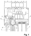
- Fig. 1
- den Gegenstand der Erfindung in einer nur teilweise wiedergegebenen Schnittdarstellung,
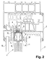
- Fig. 2
- den Gegenstand nach
Figur 1 in geringfügig modifizierter Ausgestaltung, - Fig. 3
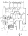
- den Gegenstand nach
Figur 1 in einer weiteren modifizierten Ausgestaltung des Klemmstücks, - Fig. 4
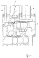
- den Gegenstand nach
Figur 1 mit einem als Metallfederprofil ausgebildeten Klemmstück, - Fig. 5
- den unteren Rand der Sonnenschutzeinrichtung.
- Die in der Zeichnung nur im Querschnitt angedeutete Sonnenschutzeinrichtung 1 ist vorgesehen für Fenster, Türen, Paneele und dergleichen, die vorzugsweise aus einer von einem Rahmen 2 eingefassten Glasfüllung 3 bestehen. Die Glasfüllung 3 ist hierbei im Rahmen 2 in üblicher Weise durch eine am Rahmen 2 angeschlossene Glashalteleiste 4 gehalten.
- Um den Antrieb 5 der Sonnenschutzeinrichtung 1 raumsparend unterzubringen, ist die Glashalteleiste 4 als Hohlprofil ausgebildet, wobei der Antrieb 5 der Sonnenschutzeinrichtung 1 innerhalb der rahmenseitig oberen Glashalteleiste 4 angeordnet ist.
- Hierdurch wird zum einen eine raumsparende Unterbringung für den Antrieb 5 erreicht, da hierfür der Raum der ohnehin erforderlichen Glashalteleiste 4 ausgenutzt wird. Zum anderen erlaubt diese Konstruktion, eine Sonnenschutzeinrichtung nur bedarfsweise vorzusehen, da durch diese Gestaltung keinerlei konstruktive Änderungen notwendig sind.
- Wie sich aus der
Fig. 2 im Einzelnen ergibt, ist die Glashalteleiste 4 von einem U-förmigen Aufnahmeprofil 6 sowie einem an den Enden der beiden freien Schenkel des U-Profils einrastbaren Deckleiste 7 gebildet. Im Profilrücken 6.1 des U-Profils sind dabei Ausnehmungen vorgesehen, durch die die Lamellen tragende Lamellenzugbänder verlaufen. - Wie weiter aus der Zeichnung folgt, rastet die Deckleiste 7 zwischen den beiden Schenkeln des Aufnahmeprofils 6 ein, wodurch auch im Bereich des Schenkelendes des U-Profils eine hohe Druckbelastbarkeit erreicht wird. An der außenseitigen Fläche der Deckleiste 7 ist eine senkrecht zur Glasfüllung 3 ausgerichtete, in ein am Rahmen 2 angeschlossenes Klemmstück 9 einrastende Einschubverbindung 8 zum Anschluß am Rahmen 2 vorgesehen.
- Bei der Ausführungsform nach
Fig. 1 ist keine Deckleiste 7 vorgesehen; hier ist die Einschubverbindung 8 direkt an dem einen Schenkel des Aufnahmeprofils 6 angeschlossen. - Im Einzelnen rastet die Deckleiste 7 mit ihrer Einschubverbindung 8 in einem Klemmstück 9 ein, das seinerseits in einer Aussparung des Rahmens 2 eingeclipst ist. Hierbei kann das Klemmstück 9 auch die Funktion eines Adapterteils aufweisen, da es Anpassungen der Anschlussmöglichkeit der Glashalteleiste 4 an den Rahmen 2 ermöglicht.
- In
Fig. 4 ist eine Ausgestaltung gezeigt, bei welcher das Klemmstück 9 von einem Metallfederprofil gebildet ist, das in eine hinterschnittene Nut am Rahmen 2 eingelegt ist. - Die Deckleiste 7 kann im Übrigen mit einer Aussparung für die Aufnahme des Anschlusskabels 10 des Antriebs 5 versehen sein.
- Um seine Funktion als Glashalteleiste 4 erfüllen zu können, ist das U-Profil an seinem der Glasfüllung 3 zugewandten Schenkel am unteren Rand außenseitig mit einem Anschlussprofil 11 versehen, das eine gegen die Glasfüllung 3 andrückende Dichtleiste 12 trägt.
- Die beiden seitlichen Glashalteleisten sind in in der Zeichnung nicht näher dargestellter Weise so ausgebildet, dass sie den seitlichen Rand der - herabgelassenen - Lamellen überdecken, so dass kein störender Lichtspalt verbleibt. In entsprechender Weise besitzt die untere Glashalteleiste - wie aus
Fig. 5 zu sehen ist - eine Aufnahme für das an der untersten Lamelle angeordnete Niederzuggewicht, so dass auch dieses bei herabgelassenen Sonnenschutz nicht sichtbar ist und sich für den Betrachter insgesamt ein homogenes Erscheinungsbild ergibt. - Im Übrigen können die Lamellen vorteilhafterweise zwischen der inneren 13 und äußeren 3 einer zweischaligen Fensteranordnung angebracht sein, wie dies im Ausführungsbeispiel in der Zeichnung dargestellt ist, wodurch die Lamellen gegen Witterungseinflüsse und Verschmutzungen geschützt sind.
Claims (12)
- Sonnenschutzeinrichtung für Fenster, Türen, Paneele oder dergleichen, die vorzugsweise aus einer von einem Rahmen (2) eingefassten Glasfüllung (3) bestehen, wobei die Glasfüllung (3) im Rahmen (2) durch eine am Rahmen (2) angeschlossene Glashalteleiste (4) gehalten ist, dadurch gekennzeichnet, dass die
Glashalteleiste (4) als Hohlprofil ausgebildet und der Antrieb (5) der Sonnenschutzeinrichtung innerhalb der rahmenseitig oberen Glashalteleiste (4) angeordnet ist. - Sonnenschutzeinrichtung nach Anspruch 1, dadurch gekennzeichnet, dass die Glashalteleiste (4) von einem U-förmigen Aufnahmeprofil (6) gebildet ist, wobei im Profilrücken (6.1) des U-Profils Ausnehmungen für den Durchtritt der Lamellenzugbänder vorgesehen sind.
- Sonnenschutzeinrichtung nach Anspruch 2, dadurch gekennzeichnet, dass an den Enden der beiden freien Schenkel des U-Profils eine Deckleiste (7) vorgesehen ist, die zwischen den beiden Schenkeln des U-Profils einrastet.
- Sonnenschutzeinrichtung nach Anspruch 3, dadurch gekennzeichnet, dass die Deckleiste (7) an ihrer außenseitigen Fläche mit einer senkrecht zur Glasfüllung (3) ausgerichteten Einschubverbindung (8) zum Anschluß am Rahmen (2) versehen ist.
- Sonnenschutzeinrichtung nach Anspruch 2, dadurch gekennzeichnet, dass am einen Schenkel des U-förmigen Aufnahmeprofils (6) eine senkrecht zur Glasfüllung (3) ausgerichtete, in ein am Rahmen (2) angeschlossenes Klemmstück (9) einrastende Einschubverbindung (8) zum Anschluß am Rahmen (2) vorgesehen ist.
- Sonnenschutzeinrichtung nach einem der Ansprüche 2 bis 4, dadurch gekennzeichnet, dass die Deckleiste (7) mit ihrer Einschubverbindung (8) in einem Klemmstück (9) einrastet, das seinerseits in einer Aussparung des Rahmens eingeclipst ist.
- Sonnenschutzeinrichtung nach einem der Ansprüche 5 oder 6, dadurch gekennzeichnet, dass das Klemmstück (9) von einem Metallfederprofil gebildet ist, das in eine hinterschnittene Nut am Rahmen (2) eingelegt ist.
- Sonnenschutzeinrichtung nach einem der Ansprüche 2 bis 4, dadurch gekennzeichnet, dass die Deckleiste (7) mit einer Aussparung zur Aufnahme des Anschlusskabels (10) für den Antrieb (5) versehen ist.
- Sonnenschutzeinrichtung nach einem der Ansprüche 1 bis 8, dadurch gekennzeichnet, dass das U-Profil an seinem der Glasfüllung (3) zugewandten Schenkel am unteren Rand außenseitig mit einem Anschlußprofil (11) für eine gegen die Glasfüllung andrückende Dichtleiste (12) versehen ist.
- Sonnenschutzeinrichtung nach einem der Ansprüche 1 bis 9, dadurch gekennzeichnet, dass die beiden seitlichen Glashalteleisten den seitlichen Rand der - herabgelassenen - Lamellen derart überdecken, dass kein störender Lichtspalt verbleibt.
- Sonnenschutzeinrichtung nach einem der Ansprüche 1 bis 10, dadurch gekennzeichnet, dass die untere Glashalteleiste eine Aufnahme für das an der untersten Lamelle angeordnete Niederzuggewicht aufweist.
- Sonnenschutzeinrichtung nach einem der Ansprüche 1 bis 11, dadurch gekennzeichnet, dass die Lamellen zwischen der inneren (13) und äußeren (3) Schale einer zweischaligen Fensteranordnung angebracht sind.
Applications Claiming Priority (1)
| Application Number | Priority Date | Filing Date | Title |
|---|---|---|---|
| DE102016009101.0A DE102016009101A1 (de) | 2016-07-27 | 2016-07-27 | Sonnenschutzeinrichtung |
Publications (3)
| Publication Number | Publication Date |
|---|---|
| EP3276116A2 true EP3276116A2 (de) | 2018-01-31 |
| EP3276116A3 EP3276116A3 (de) | 2018-06-06 |
| EP3276116B1 EP3276116B1 (de) | 2020-08-26 |
Family
ID=59485120
Family Applications (1)
| Application Number | Title | Priority Date | Filing Date |
|---|---|---|---|
| EP17001294.2A Active EP3276116B1 (de) | 2016-07-27 | 2017-07-27 | Fensteranordnung mit einer sonnenschutzeinrichtung |
Country Status (2)
| Country | Link |
|---|---|
| EP (1) | EP3276116B1 (de) |
| DE (1) | DE102016009101A1 (de) |
Cited By (1)
| Publication number | Priority date | Publication date | Assignee | Title |
|---|---|---|---|---|
| US20230142702A1 (en) * | 2021-11-05 | 2023-05-11 | Arconic Technologies Llc | Thermal dampening devices for window systems |
Families Citing this family (1)
| Publication number | Priority date | Publication date | Assignee | Title |
|---|---|---|---|---|
| CN112664119A (zh) * | 2021-01-03 | 2021-04-16 | 中绿建节能科技有限公司 | 一种节能暖边式结构内置百叶系统 |
Family Cites Families (8)
| Publication number | Priority date | Publication date | Assignee | Title |
|---|---|---|---|---|
| DE69626989T2 (de) * | 1996-11-29 | 2004-01-29 | Franciaflex S A | Fensterrahmen mit einer in hohlen lateralen Glashalteleisten integrierten Jalousie |
| NL1010426C2 (nl) * | 1998-10-29 | 2000-05-03 | Verosol Nederland Bv | Glaslat en raam voorzien van glaslat. |
| DE202007000736U1 (de) * | 2007-01-12 | 2007-04-05 | Rauh Sr Gmbh | Verbundfenster |
| DE202007008114U1 (de) * | 2007-06-09 | 2007-09-20 | Gealan Fenster-Systeme Gmbh | Lichtschutzkassette für einen Fensterflügel |
| US9103156B1 (en) * | 2008-11-25 | 2015-08-11 | Anton Koytchev Vassilev | Attachable built-in blinds for doors and windows |
| DE202012009960U1 (de) * | 2012-10-12 | 2012-11-23 | Michael Dumrath | Fenster mit integriertem Rollo |
| DE102013100299A1 (de) * | 2013-01-11 | 2014-07-31 | SCHÜCO International KG | Fenster oder Tür |
| DE202014105809U1 (de) * | 2014-12-02 | 2014-12-17 | Raico Bautechnik Gmbh | Fensteranordnung und Beschattungsvorrichtung |
-
2016
- 2016-07-27 DE DE102016009101.0A patent/DE102016009101A1/de not_active Ceased
-
2017
- 2017-07-27 EP EP17001294.2A patent/EP3276116B1/de active Active
Non-Patent Citations (1)
| Title |
|---|
| None |
Cited By (2)
| Publication number | Priority date | Publication date | Assignee | Title |
|---|---|---|---|---|
| US20230142702A1 (en) * | 2021-11-05 | 2023-05-11 | Arconic Technologies Llc | Thermal dampening devices for window systems |
| US11976511B2 (en) * | 2021-11-05 | 2024-05-07 | Arconic Technologies Llc | Thermal dampening devices for window systems |
Also Published As
| Publication number | Publication date |
|---|---|
| EP3276116B1 (de) | 2020-08-26 |
| EP3276116A3 (de) | 2018-06-06 |
| DE102016009101A1 (de) | 2018-02-01 |
Similar Documents
| Publication | Publication Date | Title |
|---|---|---|
| EP3259428B1 (de) | Dichtungsvorrichtung für fenster- und türelemente | |
| DE102013018274B4 (de) | Thermisch gedämmtes Profil | |
| DE102022206444B4 (de) | Blendrahmen für eine Tür mit Extrusionsrahmen und Schwelle, Tür mit einem derartigen Blendrahmen und Verfahren zur Herstellung dieser Tür | |
| EP3276116B1 (de) | Fensteranordnung mit einer sonnenschutzeinrichtung | |
| EP1783315B1 (de) | Schnurhalter und Endkappe für eine Verschattungsanlage sowie Verschattungsanlage | |
| EP2138666A2 (de) | Ausfachungsrahmen für Gebäudefassaden | |
| DE202009000363U1 (de) | Fenster mit integriertem Insekten- und/oder Pollenschutz | |
| DE3301176A1 (de) | Stockrahmen fuer fenster oder tueren mit aufsetzbarem rolladenkasten oder dergleichen | |
| DE202021004251U1 (de) | Vorrichtung zur Beschattung über Eck verlaufender Fenster- oder Türöffnungen | |
| EP2439371B1 (de) | Anordnung bestehend aus einer Dichtungsanordnung und einem Schiebefenster oder einer Schiebetür | |
| EP2072744B1 (de) | Zargenprofil für eine Hebe-Schiebetür | |
| DE102017108090A1 (de) | Haltesystem zum Halten eines Objekts | |
| DE1957248A1 (de) | Befestigung von Insekten-Schutzgeweben in einem Rahmen | |
| DE202005021851U1 (de) | Schiebetür | |
| DE19537190A1 (de) | Vertikaljalousielamelle | |
| DE102015201675A1 (de) | Tür- oder Fenstersystem | |
| DE102017114920A1 (de) | Eckverbund von zwei Sonnenschutzanlagen | |
| AT406786B (de) | Dichtungselement | |
| EP1304444B1 (de) | Tür-oder Fensterelement zum Einsatz in Wandausschnitte | |
| AT17970U1 (de) | Kombination eines schwenkbaren Tür- oder Fensterflügels mit einem Tür- oder Fensterstock, Kombination einer Schiebetür oder eines Schiebefenster mit einem Tür- oder Fensterstock sowie Fixfensterteil | |
| DE102015016568A1 (de) | Rahmen, insbesondere Fenster- oder Türrahmen, sowie Fenster und Tür | |
| DE202007003859U1 (de) | Führungsschiene für einen Rollladen oder einen Raffstore in einem Vorbausystem | |
| DE102022127466A1 (de) | Flügelprofil, Flügelrahmen und Verfahren zur Herstellung eines Flügelrahmens | |
| AT316829B (de) | Metallrahmen | |
| EP4390048A1 (de) | Rahmen für eine schutzvorrichtung |
Legal Events
| Date | Code | Title | Description |
|---|---|---|---|
| PUAI | Public reference made under article 153(3) epc to a published international application that has entered the european phase |
Free format text: ORIGINAL CODE: 0009012 |
|
| STAA | Information on the status of an ep patent application or granted ep patent |
Free format text: STATUS: THE APPLICATION HAS BEEN PUBLISHED |
|
| AK | Designated contracting states |
Kind code of ref document: A2 Designated state(s): AL AT BE BG CH CY CZ DE DK EE ES FI FR GB GR HR HU IE IS IT LI LT LU LV MC MK MT NL NO PL PT RO RS SE SI SK SM TR |
|
| AX | Request for extension of the european patent |
Extension state: BA ME |
|
| PUAL | Search report despatched |
Free format text: ORIGINAL CODE: 0009013 |
|
| AK | Designated contracting states |
Kind code of ref document: A3 Designated state(s): AL AT BE BG CH CY CZ DE DK EE ES FI FR GB GR HR HU IE IS IT LI LT LU LV MC MK MT NL NO PL PT RO RS SE SI SK SM TR |
|
| AX | Request for extension of the european patent |
Extension state: BA ME |
|
| RIC1 | Information provided on ipc code assigned before grant |
Ipc: E06B 9/264 20060101AFI20180502BHEP Ipc: E06B 3/64 20060101ALI20180502BHEP |
|
| STAA | Information on the status of an ep patent application or granted ep patent |
Free format text: STATUS: REQUEST FOR EXAMINATION WAS MADE |
|
| 17P | Request for examination filed |
Effective date: 20181204 |
|
| GRAP | Despatch of communication of intention to grant a patent |
Free format text: ORIGINAL CODE: EPIDOSNIGR1 |
|
| STAA | Information on the status of an ep patent application or granted ep patent |
Free format text: STATUS: GRANT OF PATENT IS INTENDED |
|
| INTG | Intention to grant announced |
Effective date: 20191118 |
|
| GRAS | Grant fee paid |
Free format text: ORIGINAL CODE: EPIDOSNIGR3 |
|
| GRAA | (expected) grant |
Free format text: ORIGINAL CODE: 0009210 |
|
| STAA | Information on the status of an ep patent application or granted ep patent |
Free format text: STATUS: THE PATENT HAS BEEN GRANTED |
|
| AK | Designated contracting states |
Kind code of ref document: B1 Designated state(s): AL AT BE BG CH CY CZ DE DK EE ES FI FR GB GR HR HU IE IS IT LI LT LU LV MC MK MT NL NO PL PT RO RS SE SI SK SM TR |
|
| REG | Reference to a national code |
Ref country code: GB Ref legal event code: FG4D Free format text: NOT ENGLISH |
|
| REG | Reference to a national code |
Ref country code: CH Ref legal event code: EP |
|
| REG | Reference to a national code |
Ref country code: DE Ref legal event code: R096 Ref document number: 502017006877 Country of ref document: DE |
|
| REG | Reference to a national code |
Ref country code: AT Ref legal event code: REF Ref document number: 1306532 Country of ref document: AT Kind code of ref document: T Effective date: 20200915 |
|
| REG | Reference to a national code |
Ref country code: IE Ref legal event code: FG4D Free format text: LANGUAGE OF EP DOCUMENT: GERMAN |
|
| REG | Reference to a national code |
Ref country code: CH Ref legal event code: NV Representative=s name: ISLER AND PEDRAZZINI AG, CH |
|
| REG | Reference to a national code |
Ref country code: LT Ref legal event code: MG4D |
|
| PG25 | Lapsed in a contracting state [announced via postgrant information from national office to epo] |
Ref country code: FI Free format text: LAPSE BECAUSE OF FAILURE TO SUBMIT A TRANSLATION OF THE DESCRIPTION OR TO PAY THE FEE WITHIN THE PRESCRIBED TIME-LIMIT Effective date: 20200826 Ref country code: PT Free format text: LAPSE BECAUSE OF FAILURE TO SUBMIT A TRANSLATION OF THE DESCRIPTION OR TO PAY THE FEE WITHIN THE PRESCRIBED TIME-LIMIT Effective date: 20201228 Ref country code: SE Free format text: LAPSE BECAUSE OF FAILURE TO SUBMIT A TRANSLATION OF THE DESCRIPTION OR TO PAY THE FEE WITHIN THE PRESCRIBED TIME-LIMIT Effective date: 20200826 Ref country code: BG Free format text: LAPSE BECAUSE OF FAILURE TO SUBMIT A TRANSLATION OF THE DESCRIPTION OR TO PAY THE FEE WITHIN THE PRESCRIBED TIME-LIMIT Effective date: 20201126 Ref country code: HR Free format text: LAPSE BECAUSE OF FAILURE TO SUBMIT A TRANSLATION OF THE DESCRIPTION OR TO PAY THE FEE WITHIN THE PRESCRIBED TIME-LIMIT Effective date: 20200826 Ref country code: LT Free format text: LAPSE BECAUSE OF FAILURE TO SUBMIT A TRANSLATION OF THE DESCRIPTION OR TO PAY THE FEE WITHIN THE PRESCRIBED TIME-LIMIT Effective date: 20200826 Ref country code: NO Free format text: LAPSE BECAUSE OF FAILURE TO SUBMIT A TRANSLATION OF THE DESCRIPTION OR TO PAY THE FEE WITHIN THE PRESCRIBED TIME-LIMIT Effective date: 20201126 Ref country code: GR Free format text: LAPSE BECAUSE OF FAILURE TO SUBMIT A TRANSLATION OF THE DESCRIPTION OR TO PAY THE FEE WITHIN THE PRESCRIBED TIME-LIMIT Effective date: 20201127 |
|
| REG | Reference to a national code |
Ref country code: NL Ref legal event code: MP Effective date: 20200826 |
|
| PG25 | Lapsed in a contracting state [announced via postgrant information from national office to epo] |
Ref country code: NL Free format text: LAPSE BECAUSE OF FAILURE TO SUBMIT A TRANSLATION OF THE DESCRIPTION OR TO PAY THE FEE WITHIN THE PRESCRIBED TIME-LIMIT Effective date: 20200826 Ref country code: LV Free format text: LAPSE BECAUSE OF FAILURE TO SUBMIT A TRANSLATION OF THE DESCRIPTION OR TO PAY THE FEE WITHIN THE PRESCRIBED TIME-LIMIT Effective date: 20200826 Ref country code: RS Free format text: LAPSE BECAUSE OF FAILURE TO SUBMIT A TRANSLATION OF THE DESCRIPTION OR TO PAY THE FEE WITHIN THE PRESCRIBED TIME-LIMIT Effective date: 20200826 Ref country code: PL Free format text: LAPSE BECAUSE OF FAILURE TO SUBMIT A TRANSLATION OF THE DESCRIPTION OR TO PAY THE FEE WITHIN THE PRESCRIBED TIME-LIMIT Effective date: 20200826 Ref country code: IS Free format text: LAPSE BECAUSE OF FAILURE TO SUBMIT A TRANSLATION OF THE DESCRIPTION OR TO PAY THE FEE WITHIN THE PRESCRIBED TIME-LIMIT Effective date: 20201226 |
|
| PG25 | Lapsed in a contracting state [announced via postgrant information from national office to epo] |
Ref country code: EE Free format text: LAPSE BECAUSE OF FAILURE TO SUBMIT A TRANSLATION OF THE DESCRIPTION OR TO PAY THE FEE WITHIN THE PRESCRIBED TIME-LIMIT Effective date: 20200826 Ref country code: SM Free format text: LAPSE BECAUSE OF FAILURE TO SUBMIT A TRANSLATION OF THE DESCRIPTION OR TO PAY THE FEE WITHIN THE PRESCRIBED TIME-LIMIT Effective date: 20200826 Ref country code: RO Free format text: LAPSE BECAUSE OF FAILURE TO SUBMIT A TRANSLATION OF THE DESCRIPTION OR TO PAY THE FEE WITHIN THE PRESCRIBED TIME-LIMIT Effective date: 20200826 Ref country code: CZ Free format text: LAPSE BECAUSE OF FAILURE TO SUBMIT A TRANSLATION OF THE DESCRIPTION OR TO PAY THE FEE WITHIN THE PRESCRIBED TIME-LIMIT Effective date: 20200826 Ref country code: DK Free format text: LAPSE BECAUSE OF FAILURE TO SUBMIT A TRANSLATION OF THE DESCRIPTION OR TO PAY THE FEE WITHIN THE PRESCRIBED TIME-LIMIT Effective date: 20200826 |
|
| REG | Reference to a national code |
Ref country code: DE Ref legal event code: R097 Ref document number: 502017006877 Country of ref document: DE |
|
| PG25 | Lapsed in a contracting state [announced via postgrant information from national office to epo] |
Ref country code: AL Free format text: LAPSE BECAUSE OF FAILURE TO SUBMIT A TRANSLATION OF THE DESCRIPTION OR TO PAY THE FEE WITHIN THE PRESCRIBED TIME-LIMIT Effective date: 20200826 Ref country code: ES Free format text: LAPSE BECAUSE OF FAILURE TO SUBMIT A TRANSLATION OF THE DESCRIPTION OR TO PAY THE FEE WITHIN THE PRESCRIBED TIME-LIMIT Effective date: 20200826 |
|
| PG25 | Lapsed in a contracting state [announced via postgrant information from national office to epo] |
Ref country code: SK Free format text: LAPSE BECAUSE OF FAILURE TO SUBMIT A TRANSLATION OF THE DESCRIPTION OR TO PAY THE FEE WITHIN THE PRESCRIBED TIME-LIMIT Effective date: 20200826 |
|
| PLBE | No opposition filed within time limit |
Free format text: ORIGINAL CODE: 0009261 |
|
| STAA | Information on the status of an ep patent application or granted ep patent |
Free format text: STATUS: NO OPPOSITION FILED WITHIN TIME LIMIT |
|
| PG25 | Lapsed in a contracting state [announced via postgrant information from national office to epo] |
Ref country code: IT Free format text: LAPSE BECAUSE OF FAILURE TO SUBMIT A TRANSLATION OF THE DESCRIPTION OR TO PAY THE FEE WITHIN THE PRESCRIBED TIME-LIMIT Effective date: 20200826 |
|
| 26N | No opposition filed |
Effective date: 20210527 |
|
| PG25 | Lapsed in a contracting state [announced via postgrant information from national office to epo] |
Ref country code: SI Free format text: LAPSE BECAUSE OF FAILURE TO SUBMIT A TRANSLATION OF THE DESCRIPTION OR TO PAY THE FEE WITHIN THE PRESCRIBED TIME-LIMIT Effective date: 20200826 |
|
| GBPC | Gb: european patent ceased through non-payment of renewal fee |
Effective date: 20210727 |
|
| PG25 | Lapsed in a contracting state [announced via postgrant information from national office to epo] |
Ref country code: MC Free format text: LAPSE BECAUSE OF FAILURE TO SUBMIT A TRANSLATION OF THE DESCRIPTION OR TO PAY THE FEE WITHIN THE PRESCRIBED TIME-LIMIT Effective date: 20200826 |
|
| REG | Reference to a national code |
Ref country code: BE Ref legal event code: MM Effective date: 20210731 |
|
| PG25 | Lapsed in a contracting state [announced via postgrant information from national office to epo] |
Ref country code: GB Free format text: LAPSE BECAUSE OF NON-PAYMENT OF DUE FEES Effective date: 20210727 |
|
| PG25 | Lapsed in a contracting state [announced via postgrant information from national office to epo] |
Ref country code: LU Free format text: LAPSE BECAUSE OF NON-PAYMENT OF DUE FEES Effective date: 20210727 Ref country code: FR Free format text: LAPSE BECAUSE OF NON-PAYMENT OF DUE FEES Effective date: 20210731 |
|
| PG25 | Lapsed in a contracting state [announced via postgrant information from national office to epo] |
Ref country code: IE Free format text: LAPSE BECAUSE OF NON-PAYMENT OF DUE FEES Effective date: 20210727 Ref country code: BE Free format text: LAPSE BECAUSE OF NON-PAYMENT OF DUE FEES Effective date: 20210731 |
|
| PG25 | Lapsed in a contracting state [announced via postgrant information from national office to epo] |
Ref country code: HU Free format text: LAPSE BECAUSE OF FAILURE TO SUBMIT A TRANSLATION OF THE DESCRIPTION OR TO PAY THE FEE WITHIN THE PRESCRIBED TIME-LIMIT; INVALID AB INITIO Effective date: 20170727 |
|
| PG25 | Lapsed in a contracting state [announced via postgrant information from national office to epo] |
Ref country code: CY Free format text: LAPSE BECAUSE OF FAILURE TO SUBMIT A TRANSLATION OF THE DESCRIPTION OR TO PAY THE FEE WITHIN THE PRESCRIBED TIME-LIMIT Effective date: 20200826 |
|
| PG25 | Lapsed in a contracting state [announced via postgrant information from national office to epo] |
Ref country code: MK Free format text: LAPSE BECAUSE OF FAILURE TO SUBMIT A TRANSLATION OF THE DESCRIPTION OR TO PAY THE FEE WITHIN THE PRESCRIBED TIME-LIMIT Effective date: 20200826 |
|
| PG25 | Lapsed in a contracting state [announced via postgrant information from national office to epo] |
Ref country code: TR Free format text: LAPSE BECAUSE OF FAILURE TO SUBMIT A TRANSLATION OF THE DESCRIPTION OR TO PAY THE FEE WITHIN THE PRESCRIBED TIME-LIMIT Effective date: 20200826 |
|
| PG25 | Lapsed in a contracting state [announced via postgrant information from national office to epo] |
Ref country code: MT Free format text: LAPSE BECAUSE OF FAILURE TO SUBMIT A TRANSLATION OF THE DESCRIPTION OR TO PAY THE FEE WITHIN THE PRESCRIBED TIME-LIMIT Effective date: 20200826 |
|
| PGFP | Annual fee paid to national office [announced via postgrant information from national office to epo] |
Ref country code: DE Payment date: 20250617 Year of fee payment: 9 |
|
| PGFP | Annual fee paid to national office [announced via postgrant information from national office to epo] |
Ref country code: AT Payment date: 20250617 Year of fee payment: 9 |
|
| PGFP | Annual fee paid to national office [announced via postgrant information from national office to epo] |
Ref country code: CH Payment date: 20250801 Year of fee payment: 9 |
|
| REG | Reference to a national code |
Ref country code: DE Ref legal event code: R082 Ref document number: 502017006877 Country of ref document: DE Representative=s name: EISENFUEHR SPEISER PATENTANWAELTE RECHTSANWAEL, DE |