EP3276201B1 - Dispositif antivibration - Google Patents
Dispositif antivibration Download PDFInfo
- Publication number
- EP3276201B1 EP3276201B1 EP16768126.1A EP16768126A EP3276201B1 EP 3276201 B1 EP3276201 B1 EP 3276201B1 EP 16768126 A EP16768126 A EP 16768126A EP 3276201 B1 EP3276201 B1 EP 3276201B1
- Authority
- EP
- European Patent Office
- Prior art keywords
- vibration
- actuator
- mounting
- actuator case
- housing
- Prior art date
- Legal status (The legal status is an assumption and is not a legal conclusion. Google has not performed a legal analysis and makes no representation as to the accuracy of the status listed.)
- Active
Links
Images


Classifications
-
- F—MECHANICAL ENGINEERING; LIGHTING; HEATING; WEAPONS; BLASTING
- F16—ENGINEERING ELEMENTS AND UNITS; GENERAL MEASURES FOR PRODUCING AND MAINTAINING EFFECTIVE FUNCTIONING OF MACHINES OR INSTALLATIONS; THERMAL INSULATION IN GENERAL
- F16F—SPRINGS; SHOCK-ABSORBERS; MEANS FOR DAMPING VIBRATION
- F16F15/00—Suppression of vibrations in systems; Means or arrangements for avoiding or reducing out-of-balance forces, e.g. due to motion
- F16F15/02—Suppression of vibrations of non-rotating, e.g. reciprocating systems; Suppression of vibrations of rotating systems by use of members not moving with the rotating systems
- F16F15/022—Suppression of vibrations of non-rotating, e.g. reciprocating systems; Suppression of vibrations of rotating systems by use of members not moving with the rotating systems using dampers and springs in combination
-
- B—PERFORMING OPERATIONS; TRANSPORTING
- B60—VEHICLES IN GENERAL
- B60K—ARRANGEMENT OR MOUNTING OF PROPULSION UNITS OR OF TRANSMISSIONS IN VEHICLES; ARRANGEMENT OR MOUNTING OF PLURAL DIVERSE PRIME-MOVERS IN VEHICLES; AUXILIARY DRIVES FOR VEHICLES; INSTRUMENTATION OR DASHBOARDS FOR VEHICLES; ARRANGEMENTS IN CONNECTION WITH COOLING, AIR INTAKE, GAS EXHAUST OR FUEL SUPPLY OF PROPULSION UNITS IN VEHICLES
- B60K5/00—Arrangement or mounting of internal-combustion or jet-propulsion units
- B60K5/12—Arrangement of engine supports
- B60K5/1208—Resilient supports
-
- B—PERFORMING OPERATIONS; TRANSPORTING
- B60—VEHICLES IN GENERAL
- B60K—ARRANGEMENT OR MOUNTING OF PROPULSION UNITS OR OF TRANSMISSIONS IN VEHICLES; ARRANGEMENT OR MOUNTING OF PLURAL DIVERSE PRIME-MOVERS IN VEHICLES; AUXILIARY DRIVES FOR VEHICLES; INSTRUMENTATION OR DASHBOARDS FOR VEHICLES; ARRANGEMENTS IN CONNECTION WITH COOLING, AIR INTAKE, GAS EXHAUST OR FUEL SUPPLY OF PROPULSION UNITS IN VEHICLES
- B60K5/00—Arrangement or mounting of internal-combustion or jet-propulsion units
- B60K5/12—Arrangement of engine supports
- B60K5/1283—Adjustable supports, e.g. the mounting or the characteristics being adjustable
-
- F—MECHANICAL ENGINEERING; LIGHTING; HEATING; WEAPONS; BLASTING
- F16—ENGINEERING ELEMENTS AND UNITS; GENERAL MEASURES FOR PRODUCING AND MAINTAINING EFFECTIVE FUNCTIONING OF MACHINES OR INSTALLATIONS; THERMAL INSULATION IN GENERAL
- F16F—SPRINGS; SHOCK-ABSORBERS; MEANS FOR DAMPING VIBRATION
- F16F13/00—Units comprising springs of the non-fluid type as well as vibration-dampers, shock-absorbers, or fluid springs
- F16F13/04—Units comprising springs of the non-fluid type as well as vibration-dampers, shock-absorbers, or fluid springs comprising both a plastics spring and a damper, e.g. a friction damper
-
- F—MECHANICAL ENGINEERING; LIGHTING; HEATING; WEAPONS; BLASTING
- F16—ENGINEERING ELEMENTS AND UNITS; GENERAL MEASURES FOR PRODUCING AND MAINTAINING EFFECTIVE FUNCTIONING OF MACHINES OR INSTALLATIONS; THERMAL INSULATION IN GENERAL
- F16F—SPRINGS; SHOCK-ABSORBERS; MEANS FOR DAMPING VIBRATION
- F16F15/00—Suppression of vibrations in systems; Means or arrangements for avoiding or reducing out-of-balance forces, e.g. due to motion
- F16F15/02—Suppression of vibrations of non-rotating, e.g. reciprocating systems; Suppression of vibrations of rotating systems by use of members not moving with the rotating systems
- F16F15/03—Suppression of vibrations of non-rotating, e.g. reciprocating systems; Suppression of vibrations of rotating systems by use of members not moving with the rotating systems using magnetic or electromagnetic means
-
- F—MECHANICAL ENGINEERING; LIGHTING; HEATING; WEAPONS; BLASTING
- F16—ENGINEERING ELEMENTS AND UNITS; GENERAL MEASURES FOR PRODUCING AND MAINTAINING EFFECTIVE FUNCTIONING OF MACHINES OR INSTALLATIONS; THERMAL INSULATION IN GENERAL
- F16F—SPRINGS; SHOCK-ABSORBERS; MEANS FOR DAMPING VIBRATION
- F16F15/00—Suppression of vibrations in systems; Means or arrangements for avoiding or reducing out-of-balance forces, e.g. due to motion
- F16F15/02—Suppression of vibrations of non-rotating, e.g. reciprocating systems; Suppression of vibrations of rotating systems by use of members not moving with the rotating systems
- F16F15/04—Suppression of vibrations of non-rotating, e.g. reciprocating systems; Suppression of vibrations of rotating systems by use of members not moving with the rotating systems using elastic means
- F16F15/08—Suppression of vibrations of non-rotating, e.g. reciprocating systems; Suppression of vibrations of rotating systems by use of members not moving with the rotating systems using elastic means with rubber springs ; with springs made of rubber and metal
-
- F—MECHANICAL ENGINEERING; LIGHTING; HEATING; WEAPONS; BLASTING
- F16—ENGINEERING ELEMENTS AND UNITS; GENERAL MEASURES FOR PRODUCING AND MAINTAINING EFFECTIVE FUNCTIONING OF MACHINES OR INSTALLATIONS; THERMAL INSULATION IN GENERAL
- F16F—SPRINGS; SHOCK-ABSORBERS; MEANS FOR DAMPING VIBRATION
- F16F7/00—Vibration-dampers; Shock-absorbers
- F16F7/10—Vibration-dampers; Shock-absorbers using inertia effect
- F16F7/1005—Vibration-dampers; Shock-absorbers using inertia effect characterised by active control of the mass
- F16F7/1011—Vibration-dampers; Shock-absorbers using inertia effect characterised by active control of the mass by electromagnetic means
Definitions
- the present invention relates to a vibration-proofing device.
- a vibration-proofing device which includes a first mounting member connected to one of a vibration generation unit and a vibration reception unit, a second mounting member connected to the other, an actuator which dampens and absorbs the input vibration by reciprocally moving a movable element in accordance with the input vibration, an actuator case which houses the actuator therein, and a terminal mounted on the actuator case to electrically connect a connector of the actuator and an external power supply, and in which the actuator case is formed by insert molding using the terminal as an insert product is known. Attention is also drawn to the disclosures of EP2610522 and DE102007038538 .
- EP 2 610 522 is the prior art closest to the subject-matter of claim 1.
- the actuator case is formed by insert molding using the terminal as the insert, there is a problem of difficulty in manufacturing the actuator case.
- the present invention has been made in view of such circumstances, and an object thereof is to provide a vibration-proofing device which can be easily manufactured while the sealing property inside the actuator case is maintained.
- the vibration-proofing device of the present invention is as claimed in claim 1.
- the present invention it is possible to easily manufacture the actuator case while maintaining the sealing property inside the actuator case.
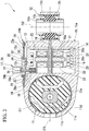
- the vibration-proofing device 1 includes a first mounting member 11 connected to one of a vibration generation unit and a vibration reception unit, a second mounting member 12 connected to the other, an actuator 14 for damping and absorbing the input vibration by reciprocally moving a movable element 13 in accordance with the input vibration, an actuator case 15 for housing the actuator 14 therein, and a relay connector 17 that is mounted on the actuator case 15 to electrically connect a connector 16 of the actuator 14 and an external power source (not shown).
- the first mounting member 11 and the second mounting member 12 include inner cylinders 11a and 12a, outer cylinders 11b and 12b surrounding the inner cylinders 11a and 12a from outside in the radial direction, and elastic bodies 11c and 12c which connect the inner cylinders 11a and 12a and the outer cylinders 11b and 12b, respectively.
- the inner cylinders 11a and 12a and the outer cylinders 11b and 12b are formed of, for example, a metal material, a resin material, or the like, and the elastic bodies 1111e and 12c are formed of, for example, a rubber material or the like.
- the first mounting member 11 is formed to have a larger diameter than the second mounting member 12.
- the outer cylinder 11b of the first mounting member 11 is formed to have a larger diameter than the outer cylinder 12b of the second mounting member 12.
- the elastic body lie of the first mounting member 11 has a larger volume than the elastic body 12c of the second mounting member 12.
- the spring constant of the first mounting member 11 is lower than the spring constant of the second mounting member 12.
- each of the inner cylinder 11a, the outer cylinder 11b, and the elastic body 11c is disposed coaxially with the first central axis O1.
- each of the inner cylinder 12a, the outer cylinder 12b, and the elastic body 12c is disposed coaxially with the second central axis 02.
- the first central axis 01 extends parallel to an imaginary axis when the second central axis 02 is rotated 90° about a connection axis 03 which connects the first central axis 01 and the second central axis 02 and is orthogonal to both the first central axis O1 and the second central axis 02. That is, the vibration-proofing device 1 is configured so that, for example, when the first central axis 01 is disposed to extend in the horizontal direction, the second central axis 02 extends in the vertical direction.
- the actuator 14 includes a support shaft 18 extending in the direction of the connection axis 03, an annular winding core 19 fitted to the support shaft 18 from the outside, two annular holders 20 that are fitted to the support shaft 18 from the outside and sandwich the winding core 19 in the direction of the connection axis 03, a coil 21 held by each holder 20, a cylindrical movable element 13 that surrounds the winding core 19 and the holder 20 over the entire circumference around the connection axis 03, a plurality of pairs of permanent magnets 23 disposed on the inner peripheral surface of the movable element 13, and an elastic support 22 that connects the movable element 13 and the support shaft 18.
- Both end portions of the support shaft 18 in the direction of the connection axis 03 are fitted to the mounting holes formed in portions of the inner surface of the actuator case 15 that face each other in the direction of the connection axis 03.
- the holder 20 includes an inner cylinder 20a fitted to the support shaft 18 from the outside, an outer cylinder 20b surrounding the inner cylinder 20a, and a connecting plate 20c that connects the end portions of the inner cylinder 20a and the outer cylinder 20b on the winding core 19 side.
- the connector 16 for supplying power to the coil 21 is provided in the holder 20.
- a part of the connector 16 protrudes from the holder 20 toward the other end opening 15e of an actuator case 15 to be described later.
- a surrounding cylinder 24 that protrudes toward the other end opening 15e of the actuator case 15 and surrounds the part of the connector 16 is provided.
- the surrounding cylinder 24 and the part of the connector 16 are disposed in the outer cylinder 20b of the two holders 20 located on the side of the first mounting member 11.
- the movable element 13 is disposed in the actuator case 15 to be reciprocally movable so that the movable element 13 approaches one of the first mounting member 11 and the second mounting member 12 and moves away from the other.
- the movable element 13 is disposed to be reciprocally movable in the direction of the connection axis 03.
- the pair of permanent magnets 23 are disposed so that the mutually opposite magnetic poles face each other across the connection axis 03.
- a plurality of pairs of permanent magnets 23 are arranged consecutively in the direction of the connection axis 03. In each of the permanent magnets 23 adjacent to each other in this direction, opposite magnetic poles are adjacent to each other.
- the elastic support 22 is formed in an elastically deformable plate shape, and has a through-hole into which the support shaft 18 is fitted.
- the elastic support 22 is connected to the end portion of the movable element 13 on the side of the second mounting member 12.
- the actuator case 15 connects the first mounting member 11 and the second mounting member 12.
- the respective outer cylinders 11b and 12b of the first mounting member 11 and the second mounting member 12 are fitted into the outer shells 11d and 12d, and the respective outer shells lid and 12d are integrally formed with the actuator case 15.
- the actuator case 15 is formed in a cylindrical shape having one end closed and the other end open, and includes a main body portion 15a inside of which the actuator 14 is housed, and a lid body 15b which closes the other end opening 15e of the main body portion 15a. Further, the main body portion 15a and the lid body 15b may be integrally formed.
- the actuator case 15 is formed in a cylindrical shape extending parallel to the second central axis 02.
- An annular seal rubber 25 is disposed between the peripheral edge portion of the other end opening 15e of the main body portion 15a and the lid body 15b.
- the lid body 15b is fixed to the main body portion 15a by a plurality of screws 26.
- the relay connector 17 includes a terminal 27 which connects the connector 16 of the actuator 14 and an external power source (not shown), and a housing 28 in which the terminal 27 is installed.
- the housing 28 is formed in a cylindrical shape extending parallel to the second central axis 02, and the terminal 27 is formed in a rod shape extending in parallel with the second central axis 02.
- the housing 28 includes the inner connecting portion 28a fitted to the surrounding cylinder 24 of the actuator 14, the outer connecting portion 28b protruding outward from the actuator case 15, and a flange portion 28c located between the inner connecting portion 28a and the outer connecting portion 28b and protruding outward in the radial direction.
- the housing 28 is integrally formed of, for example, a thermoplastic resin or the like.
- the actuator case 15 is formed with an insertion hole 31 through which the terminal 27 of the relay connector 17 is inserted, and a mounting cylinder 32 surrounding the insertion hole 31 is provided to protrude.
- an insertion hole 31 is formed in the lid body 15b.
- the inner connecting portion 28a of the housing 28 is inserted into the insertion hole 31, and when the inner connecting portion 28a is fitted to the surrounding cylinder 24 of the actuator 14 through the insertion hole 31, the terminal 27 is electrically connected to the connector 16 of the actuator 14.
- the mounting cylinder 32 extends in parallel to the second central axis 02.
- a portion 15c (hereinafter referred to as an inner portion) of the lid body 15b located inside the mounting cylinder 32 protrudes to the inside of the actuator case 15 beyond a portion 15d (see the outer portion) located outside the mounting cylinder 32. Further, the inner portion 15c may protrude to the outside of the actuator case 15 beyond the outer portion 15d.
- one of the mounting cylinder 32 and the housing 28 is fitted to the inside of the other thereof and is airtightly fitted via an annular packing 35.
- the flange portion 28c of the housing 28 is fitted into the mounting cylinder 32 via the packing 35.
- a cylindrical body may be disposed in the housing 28, and the mounting cylinder 32 may be fitted inside the cylindrical body.
- the mounting cylinder 32 is formed in a cylindrical shape, and the packing 35 is formed in an annular shape. Therefore, it is possible to equalize the radial compression force applied to the packing 35 over the entire circumference.
- An annular groove extending over the entire circumference is formed on the outer peripheral surface of the flange portion 28c, and the packing 35 is fitted into the annular groove. Therefore, it is possible to prevent the packing 35 from being misaligned with respect to the mounting cylinder 32 due to input vibration.
- the packing 35 is entirely covered with the mounting cylinder 32 and the flange portion 28c. Further, the packing 35 is not limited to a ring shape extending continuously over the entire circumference, but may have, be example, a ring with a C shape in which a part is cut.
- the mounting cylinder 32 protrudes from both the front and back surfaces of the outer portion 15d of the lid body 15b. This makes it possible to extend the length of the mounting cylinder 32 while suppressing the amount of protrusion of the mounting cylinder 32 from the outer portion 15d of the lid body 15b and to easily enhance the rigidity of the mounting cylinder 32. Therefore, the sealing property between the mounting cylinder 32 and the housing 28 can be securely ensured.
- the packing 35 is disposed on a portion of the inner peripheral surface of the mounting cylinder 32 that is located on the same plane as the front and back surfaces of the outer portion 15d of the lid body 15b.
- the mounting cylinder 32 is formed by drawing the lid body 15b.
- the opening peripheral edge portion of the mounting cylinder 32 in the outer portion 15d of the lid body 15b is folded back in a direction opposite to the direction in which the lid body 15b is drawn when the mounting cylinder 32 is formed.
- the mounting cylinder 32 and the lid body 15b may be separate bodies. In this case, the mounting cylinder 32 and the lid body 15b may adhere or be welded together. Further, when the mounting cylinder 32 and the lid body 15b are integrated, they may be formed by casting, injection molding, or the like.
- a mounting hole 34 into which the fitting protrusion 33 formed in the housing 28 is fitted is formed in the inner portion 15c of the lid body 15b.
- a plurality of fitting protrusions 33 are formed on the flange portion 28c of the housing 28 and protrude toward the inside of the actuator case 15.
- the fitting protrusion 33 has a rod shape.
- the portion protruding from the back surface of the lid body 15b to the inside of the actuator case 15 is heated, is expanded by being crushed toward the back surface of the lid body 15b to form an engaging portion, and is bonded to the back surface of the lid body 15b.
- the flange portion 28c and the fitting protrusion 33 sandwich the inner portion 15c of the lid body 15b, thereby fixing the housing 28 to the lid body 15b. Further, the fitting protrusion 33 may not adhere to the back surface of the lid body 15b.
- the vibration-proofing device 1 In the state in which the vibration-proofing device 1 is disposed on a vehicle so that vibration is input in the direction of the connection axis 03, when vibration of a frequency component incapable of being absorbed by the first mounting member 11 is input, the movable element 13 is reciprocally moved in the direction of the connection axis 03 with the amplitude and frequency calculated by control means (not shown) at the opposite phase to the input vibration. Thus, the input vibration is dampened and absorbed.
- the vibration-proofing device 1 may be, for example, disposed on the vehicle so that the direction of the connection axis 03 coincides with the longitudinal direction of the vehicle.
- the first mounting member 11 dampens and absorbs most of the input vibration from the engine. Therefore, it is possible to suppress the specification of the actuator 14 to the necessary minimum, and it is possible to suppress an increase in cost of the vibration-proofing device 1.
- the housing 28 is airtightly fitted into the mounting cylinder 32 via the annular packing 35.
- the housing 28 is deformed due to vibration that is input to the vibration-proofing device 1 or displaced with respect to the actuator case 15, as long as the housing 28 is fitted into the mounting cylinder 32, it is possible to make it difficult to release the sealing property between the inner peripheral surface of the mounting cylinder 32 and the outer peripheral surface of the housing 28. Therefore, it is possible to easily and reliably prevent communication between the inside and the outside of the actuator case 15 through the insertion hole 31.
- the vibration-proofing device 1 can be easily manufactured as compared with a case in which the actuator case is formed by insert molding with the terminal as the insert.
- the housing 28 is disposed inside the mounting cylinder 32, it is possible to suppress the protrusion of the housing 28 from the actuator case 15. Therefore, protrusion of the vibration-proofing device 1 can be suppressed.
- the housing 28 is not fitted into the mounting cylinder 32, and the fitting protrusion 33 of the housing 28 is fitted into the mounting hole 34 of the actuator case 15. Accordingly, the housing 28 can be firmly fixed to the actuator case 15.
- the mounting hole 34 is located inside the mounting cylinder 32 of the actuator case 15 and is formed in a portion airtightly sealed to the outside of the actuator case 15 by the packing 35, it is possible to prevent communication between the inside and the outside of the actuator case 15 through the mounting hole 34.
- the vibration-proofing device 1 a configuration having the first mounting member 11 and the second mounting member 12 connected via the actuator case 15 has been described.
- the present invention is not limited thereto, and the invention is also applicable to a vibration-proofing device which includes a cylindrical first mounting member, a second mounting member disposed radially inside the first mounting member, an elastic member connecting the first mounting member and the second mounting member, a movable plate defining a liquid chamber between the elastic member and the movable plate, and a movable element connected to the movable plate, and includes an actuator which excites the movable plate by reciprocally moving the movable element to dampen and absorb the input vibration, and an actuator case which houses the actuator therein.
- a fitting protrusion 41 which includes a shaft portion 41a protruding from the flange portion 28c, and a locking portion 41b formed to be elastically deformable at the distal end portion of the shaft portion 41 a and gradually enlarged in diameter from the distal end toward the flange portion 28c may be adopted.
- the locking portion 41b comes into slide-contact with the opening peripheral edge portion of the mounting hole 34 in the actuator case 15 and is deformed to be reduced in diameter, and when passing through the mounting hole 34, the locking portion 41b is deformed to be restored.
- the flange portion 28c and the locking portion 41b of the fitting protrusion 41 sandwich the inner portion 15c of the lid body 15b, thereby fixing the housing 28 to the lid body 15b.
- the device can be easily manufactured while the sealing property of the inside of the actuator case is maintained.
Landscapes
- Engineering & Computer Science (AREA)
- General Engineering & Computer Science (AREA)
- Mechanical Engineering (AREA)
- Physics & Mathematics (AREA)
- Acoustics & Sound (AREA)
- Aviation & Aerospace Engineering (AREA)
- Chemical & Material Sciences (AREA)
- Combustion & Propulsion (AREA)
- Electromagnetism (AREA)
- Transportation (AREA)
- Combined Devices Of Dampers And Springs (AREA)
- Vibration Prevention Devices (AREA)
Claims (2)
- Dispositif anti-vibration (1) comprenant :un premier élément de montage (11) qui est connecté à une unité prise parmi une unité de génération de vibrations et une unité de réception de vibrations, et un second élément de montage (12) qui est connecté à l'autre unité ;un actionneur (14) qui amortit et absorbe une vibration d'entrée en déplaçant en va-et-vient un élément mobile (13) en fonction de la vibration d'entrée ;un carter d'actionneur (15) qui loge l'actionneur (14) en son sein et qui inclut une partie de corps principale (15a) et un corps de couvercle (15b) ; etun connecteur de relais (17) qui est monté sur le carter d'actionneur (15) et qui connecte électriquement un connecteur (16) de l'actionneur (14) et une source d'alimentation électrique externe ;dans lequel le connecteur de relais (17) inclut une borne (27) qui connecte le connecteur (16) de l'actionneur (14) et la source d'alimentation électrique externe, et un logement (28) à l'intérieur duquel la borne (27) est installée ;le carter d'actionneur (15) est formé de sorte qu'il soit muni d'un trou d'insertion (31) au travers duquel la borne (27) est insérée, et un cylindre de montage (32) qui entoure le trou d'insertion (31) est prévu et fait saillie depuis le carter d'actionneur (15) ;le logement (28) est adapté de façon étanche à l'air sur l'intérieur du cylindre de montage (32) via une garniture d'étanchéité (35) ; etle corps de couvercle (15b) comporte une partie externe (15d) qui est située à l'extérieur du cylindre de montage (32), et le cylindre de montage (32) fait saillie depuis à la fois des surfaces avant et arrière de la partie externe (15d) du corps de couvercle (15b) jusqu'à l'intérieur et jusqu'à l'extérieur du carter d'actionneur (15).
- Dispositif anti-vibration (1) selon la revendication 1, dans lequel un trou de montage (34) est formé dans une partie du carter d'actionneur (15) qui est localisée à l'intérieur du cylindre de montage (32), une protubérance d'adaptation (33) qui est formée dans le logement (28) étant adaptée sur le trou de montage (34).
Applications Claiming Priority (2)
| Application Number | Priority Date | Filing Date | Title |
|---|---|---|---|
| JP2015064062A JP6442341B2 (ja) | 2015-03-26 | 2015-03-26 | 防振装置 |
| PCT/JP2016/051731 WO2016152223A1 (fr) | 2015-03-26 | 2016-01-21 | Dispositif antivibration |
Publications (3)
| Publication Number | Publication Date |
|---|---|
| EP3276201A1 EP3276201A1 (fr) | 2018-01-31 |
| EP3276201A4 EP3276201A4 (fr) | 2018-05-02 |
| EP3276201B1 true EP3276201B1 (fr) | 2020-01-15 |
Family
ID=56978214
Family Applications (1)
| Application Number | Title | Priority Date | Filing Date |
|---|---|---|---|
| EP16768126.1A Active EP3276201B1 (fr) | 2015-03-26 | 2016-01-21 | Dispositif antivibration |
Country Status (5)
| Country | Link |
|---|---|
| US (1) | US10316928B2 (fr) |
| EP (1) | EP3276201B1 (fr) |
| JP (1) | JP6442341B2 (fr) |
| CN (1) | CN107360724B (fr) |
| WO (1) | WO2016152223A1 (fr) |
Families Citing this family (4)
| Publication number | Priority date | Publication date | Assignee | Title |
|---|---|---|---|---|
| DE102015122226B4 (de) * | 2015-12-18 | 2022-05-19 | Vibracoustic Se | Motorlager-Pendelstützen-Vorrichtung |
| FR3068649B1 (fr) * | 2017-07-10 | 2021-11-26 | Renault Sas | Dispositif monobloc de support d'un groupe motopropulseur integrant un palier relais |
| US10619615B2 (en) * | 2017-10-03 | 2020-04-14 | Polaris Industries Inc. | Crankcase mounts and reinforced rubber in mount on force vector |
| DE102019112334A1 (de) * | 2019-05-10 | 2020-11-12 | Eto Magnetic Gmbh | Aktorvorrichtung zur aktiven Schwingungsreduzierung, -dämpfung und/oder -tilgung |
Family Cites Families (17)
| Publication number | Priority date | Publication date | Assignee | Title |
|---|---|---|---|---|
| JPS5773256A (en) * | 1980-10-22 | 1982-05-07 | Aisin Warner Ltd | Sealing wire terminal |
| JP2524095Y2 (ja) * | 1991-04-15 | 1997-01-29 | 住友電装株式会社 | 自動車エンジンの高圧接続部のキヤップ |
| JPH08138785A (ja) * | 1994-11-10 | 1996-05-31 | Yazaki Corp | シャッター機構付コネクタ |
| US6028523A (en) * | 1998-06-25 | 2000-02-22 | Carrier Corporation | Integral ground pin for sealed compressor |
| JP4020358B2 (ja) * | 2001-10-01 | 2007-12-12 | 矢崎総業株式会社 | 端子防油水構造 |
| JP2005019188A (ja) * | 2003-06-26 | 2005-01-20 | Auto Network Gijutsu Kenkyusho:Kk | 機器用コネクタ |
| JP2006140089A (ja) * | 2004-11-15 | 2006-06-01 | Yazaki Corp | 待受けコネクタの嵌合構造 |
| JP2007218418A (ja) * | 2005-07-19 | 2007-08-30 | Toyo Tire & Rubber Co Ltd | 能動型液封入式防振装置 |
| JP2008222073A (ja) * | 2007-03-13 | 2008-09-25 | Toyota Motor Corp | 車両用サスペンション装置 |
| DE102007038538A1 (de) * | 2007-08-16 | 2009-02-19 | Robert Bosch Gmbh | Gehäuse für eine elektrische Schaltung, insbesondere eines Steuergeräts eines Fahrzeugs |
| JP2010255787A (ja) | 2009-04-27 | 2010-11-11 | Bridgestone Corp | 防振装置 |
| JP5399800B2 (ja) * | 2009-07-17 | 2014-01-29 | 矢崎総業株式会社 | 防水構造 |
| JP5592659B2 (ja) * | 2010-01-28 | 2014-09-17 | 株式会社ケーヒン | 能動型防振装置 |
| JP5641817B2 (ja) * | 2010-08-23 | 2014-12-17 | 株式会社ブリヂストン | トルクロッド |
| EP2610522B1 (fr) * | 2010-08-23 | 2015-04-15 | Bridgestone Corporation | Barre de torsion et système de montage de moteur qui utilise cette dernière |
| US8777647B2 (en) * | 2010-12-07 | 2014-07-15 | Delta Systems, Inc. | Connection system and method |
| JP5831061B2 (ja) * | 2011-01-19 | 2015-12-09 | 日立金属株式会社 | コネクタ |
-
2015
- 2015-03-26 JP JP2015064062A patent/JP6442341B2/ja active Active
-
2016
- 2016-01-21 CN CN201680017601.0A patent/CN107360724B/zh active Active
- 2016-01-21 US US15/559,288 patent/US10316928B2/en active Active
- 2016-01-21 WO PCT/JP2016/051731 patent/WO2016152223A1/fr not_active Ceased
- 2016-01-21 EP EP16768126.1A patent/EP3276201B1/fr active Active
Non-Patent Citations (1)
| Title |
|---|
| None * |
Also Published As
| Publication number | Publication date |
|---|---|
| JP2016183721A (ja) | 2016-10-20 |
| WO2016152223A1 (fr) | 2016-09-29 |
| JP6442341B2 (ja) | 2018-12-19 |
| CN107360724A (zh) | 2017-11-17 |
| EP3276201A1 (fr) | 2018-01-31 |
| US20180058537A1 (en) | 2018-03-01 |
| CN107360724B (zh) | 2019-06-18 |
| US10316928B2 (en) | 2019-06-11 |
| EP3276201A4 (fr) | 2018-05-02 |
Similar Documents
| Publication | Publication Date | Title |
|---|---|---|
| EP3276201B1 (fr) | Dispositif antivibration | |
| CN108980261B (zh) | 隔振装置 | |
| EP2642152B1 (fr) | Dispositif d'isolation antivibratoire et support pour dispositif d'isolation antivibratoire | |
| EP3203107B1 (fr) | Douille remplie de liquide | |
| US10316927B2 (en) | Hydromount for mounting a motor vehicle engine | |
| EP3184853B1 (fr) | Dispositif d'isolation de vibrations | |
| EP2620669B1 (fr) | Dispositif anti-vibratoire | |
| JP5837398B2 (ja) | 電磁式アクチュエータとそれを用いた能動型制振器 | |
| US10018241B2 (en) | Vibration isolator | |
| EP3369962B1 (fr) | Bielle de poussée | |
| JPWO2010126059A1 (ja) | 防振装置 | |
| JP5221442B2 (ja) | 防振装置 | |
| JP2015224651A (ja) | 液封入式防振装置 | |
| JP2018053945A (ja) | 防振装置 | |
| WO2018062165A1 (fr) | Dispositif d'amortissement de vibrations | |
| JP6570980B2 (ja) | 防振装置 | |
| US9664309B2 (en) | Integral pump mount and hose attachment for a vehicle | |
| JP2008240841A (ja) | 防振装置 | |
| JP2016075323A (ja) | 防振装置 | |
| JP2018053946A (ja) | 防振装置 | |
| JP2019196791A (ja) | トルクロッド | |
| JP2014211193A (ja) | 防振装置 |
Legal Events
| Date | Code | Title | Description |
|---|---|---|---|
| STAA | Information on the status of an ep patent application or granted ep patent |
Free format text: STATUS: THE INTERNATIONAL PUBLICATION HAS BEEN MADE |
|
| PUAI | Public reference made under article 153(3) epc to a published international application that has entered the european phase |
Free format text: ORIGINAL CODE: 0009012 |
|
| STAA | Information on the status of an ep patent application or granted ep patent |
Free format text: STATUS: REQUEST FOR EXAMINATION WAS MADE |
|
| 17P | Request for examination filed |
Effective date: 20170921 |
|
| AK | Designated contracting states |
Kind code of ref document: A1 Designated state(s): AL AT BE BG CH CY CZ DE DK EE ES FI FR GB GR HR HU IE IS IT LI LT LU LV MC MK MT NL NO PL PT RO RS SE SI SK SM TR |
|
| AX | Request for extension of the european patent |
Extension state: BA ME |
|
| A4 | Supplementary search report drawn up and despatched |
Effective date: 20180405 |
|
| RIC1 | Information provided on ipc code assigned before grant |
Ipc: F16F 15/03 20060101AFI20180329BHEP Ipc: F16F 15/08 20060101ALI20180329BHEP Ipc: B60K 5/12 20060101ALI20180329BHEP Ipc: F16F 15/02 20060101ALI20180329BHEP Ipc: F16F 7/10 20060101ALI20180329BHEP Ipc: F16F 13/04 20060101ALI20180329BHEP |
|
| DAV | Request for validation of the european patent (deleted) | ||
| DAX | Request for extension of the european patent (deleted) | ||
| STAA | Information on the status of an ep patent application or granted ep patent |
Free format text: STATUS: EXAMINATION IS IN PROGRESS |
|
| 17Q | First examination report despatched |
Effective date: 20190313 |
|
| GRAP | Despatch of communication of intention to grant a patent |
Free format text: ORIGINAL CODE: EPIDOSNIGR1 |
|
| STAA | Information on the status of an ep patent application or granted ep patent |
Free format text: STATUS: GRANT OF PATENT IS INTENDED |
|
| INTG | Intention to grant announced |
Effective date: 20190918 |
|
| GRAS | Grant fee paid |
Free format text: ORIGINAL CODE: EPIDOSNIGR3 |
|
| GRAA | (expected) grant |
Free format text: ORIGINAL CODE: 0009210 |
|
| STAA | Information on the status of an ep patent application or granted ep patent |
Free format text: STATUS: THE PATENT HAS BEEN GRANTED |
|
| AK | Designated contracting states |
Kind code of ref document: B1 Designated state(s): AL AT BE BG CH CY CZ DE DK EE ES FI FR GB GR HR HU IE IS IT LI LT LU LV MC MK MT NL NO PL PT RO RS SE SI SK SM TR |
|
| REG | Reference to a national code |
Ref country code: CH Ref legal event code: EP Ref country code: GB Ref legal event code: FG4D |
|
| REG | Reference to a national code |
Ref country code: IE Ref legal event code: FG4D |
|
| REG | Reference to a national code |
Ref country code: DE Ref legal event code: R096 Ref document number: 602016028361 Country of ref document: DE |
|
| REG | Reference to a national code |
Ref country code: AT Ref legal event code: REF Ref document number: 1225422 Country of ref document: AT Kind code of ref document: T Effective date: 20200215 |
|
| REG | Reference to a national code |
Ref country code: NL Ref legal event code: MP Effective date: 20200115 |
|
| REG | Reference to a national code |
Ref country code: LT Ref legal event code: MG4D |
|
| PG25 | Lapsed in a contracting state [announced via postgrant information from national office to epo] |
Ref country code: NL Free format text: LAPSE BECAUSE OF FAILURE TO SUBMIT A TRANSLATION OF THE DESCRIPTION OR TO PAY THE FEE WITHIN THE PRESCRIBED TIME-LIMIT Effective date: 20200115 Ref country code: PT Free format text: LAPSE BECAUSE OF FAILURE TO SUBMIT A TRANSLATION OF THE DESCRIPTION OR TO PAY THE FEE WITHIN THE PRESCRIBED TIME-LIMIT Effective date: 20200607 Ref country code: NO Free format text: LAPSE BECAUSE OF FAILURE TO SUBMIT A TRANSLATION OF THE DESCRIPTION OR TO PAY THE FEE WITHIN THE PRESCRIBED TIME-LIMIT Effective date: 20200415 Ref country code: RS Free format text: LAPSE BECAUSE OF FAILURE TO SUBMIT A TRANSLATION OF THE DESCRIPTION OR TO PAY THE FEE WITHIN THE PRESCRIBED TIME-LIMIT Effective date: 20200115 Ref country code: FI Free format text: LAPSE BECAUSE OF FAILURE TO SUBMIT A TRANSLATION OF THE DESCRIPTION OR TO PAY THE FEE WITHIN THE PRESCRIBED TIME-LIMIT Effective date: 20200115 |
|
| PG25 | Lapsed in a contracting state [announced via postgrant information from national office to epo] |
Ref country code: LV Free format text: LAPSE BECAUSE OF FAILURE TO SUBMIT A TRANSLATION OF THE DESCRIPTION OR TO PAY THE FEE WITHIN THE PRESCRIBED TIME-LIMIT Effective date: 20200115 Ref country code: SE Free format text: LAPSE BECAUSE OF FAILURE TO SUBMIT A TRANSLATION OF THE DESCRIPTION OR TO PAY THE FEE WITHIN THE PRESCRIBED TIME-LIMIT Effective date: 20200115 Ref country code: HR Free format text: LAPSE BECAUSE OF FAILURE TO SUBMIT A TRANSLATION OF THE DESCRIPTION OR TO PAY THE FEE WITHIN THE PRESCRIBED TIME-LIMIT Effective date: 20200115 Ref country code: BG Free format text: LAPSE BECAUSE OF FAILURE TO SUBMIT A TRANSLATION OF THE DESCRIPTION OR TO PAY THE FEE WITHIN THE PRESCRIBED TIME-LIMIT Effective date: 20200415 Ref country code: GR Free format text: LAPSE BECAUSE OF FAILURE TO SUBMIT A TRANSLATION OF THE DESCRIPTION OR TO PAY THE FEE WITHIN THE PRESCRIBED TIME-LIMIT Effective date: 20200416 Ref country code: IS Free format text: LAPSE BECAUSE OF FAILURE TO SUBMIT A TRANSLATION OF THE DESCRIPTION OR TO PAY THE FEE WITHIN THE PRESCRIBED TIME-LIMIT Effective date: 20200515 |
|
| REG | Reference to a national code |
Ref country code: CH Ref legal event code: PL |
|
| REG | Reference to a national code |
Ref country code: BE Ref legal event code: MM Effective date: 20200131 |
|
| REG | Reference to a national code |
Ref country code: DE Ref legal event code: R097 Ref document number: 602016028361 Country of ref document: DE |
|
| PG25 | Lapsed in a contracting state [announced via postgrant information from national office to epo] |
Ref country code: LT Free format text: LAPSE BECAUSE OF FAILURE TO SUBMIT A TRANSLATION OF THE DESCRIPTION OR TO PAY THE FEE WITHIN THE PRESCRIBED TIME-LIMIT Effective date: 20200115 Ref country code: CZ Free format text: LAPSE BECAUSE OF FAILURE TO SUBMIT A TRANSLATION OF THE DESCRIPTION OR TO PAY THE FEE WITHIN THE PRESCRIBED TIME-LIMIT Effective date: 20200115 Ref country code: SM Free format text: LAPSE BECAUSE OF FAILURE TO SUBMIT A TRANSLATION OF THE DESCRIPTION OR TO PAY THE FEE WITHIN THE PRESCRIBED TIME-LIMIT Effective date: 20200115 Ref country code: EE Free format text: LAPSE BECAUSE OF FAILURE TO SUBMIT A TRANSLATION OF THE DESCRIPTION OR TO PAY THE FEE WITHIN THE PRESCRIBED TIME-LIMIT Effective date: 20200115 Ref country code: RO Free format text: LAPSE BECAUSE OF FAILURE TO SUBMIT A TRANSLATION OF THE DESCRIPTION OR TO PAY THE FEE WITHIN THE PRESCRIBED TIME-LIMIT Effective date: 20200115 Ref country code: ES Free format text: LAPSE BECAUSE OF FAILURE TO SUBMIT A TRANSLATION OF THE DESCRIPTION OR TO PAY THE FEE WITHIN THE PRESCRIBED TIME-LIMIT Effective date: 20200115 Ref country code: LU Free format text: LAPSE BECAUSE OF NON-PAYMENT OF DUE FEES Effective date: 20200121 Ref country code: DK Free format text: LAPSE BECAUSE OF FAILURE TO SUBMIT A TRANSLATION OF THE DESCRIPTION OR TO PAY THE FEE WITHIN THE PRESCRIBED TIME-LIMIT Effective date: 20200115 Ref country code: SK Free format text: LAPSE BECAUSE OF FAILURE TO SUBMIT A TRANSLATION OF THE DESCRIPTION OR TO PAY THE FEE WITHIN THE PRESCRIBED TIME-LIMIT Effective date: 20200115 Ref country code: MC Free format text: LAPSE BECAUSE OF FAILURE TO SUBMIT A TRANSLATION OF THE DESCRIPTION OR TO PAY THE FEE WITHIN THE PRESCRIBED TIME-LIMIT Effective date: 20200115 |
|
| REG | Reference to a national code |
Ref country code: AT Ref legal event code: MK05 Ref document number: 1225422 Country of ref document: AT Kind code of ref document: T Effective date: 20200115 |
|
| PLBE | No opposition filed within time limit |
Free format text: ORIGINAL CODE: 0009261 |
|
| STAA | Information on the status of an ep patent application or granted ep patent |
Free format text: STATUS: NO OPPOSITION FILED WITHIN TIME LIMIT |
|
| PG25 | Lapsed in a contracting state [announced via postgrant information from national office to epo] |
Ref country code: BE Free format text: LAPSE BECAUSE OF NON-PAYMENT OF DUE FEES Effective date: 20200131 Ref country code: CH Free format text: LAPSE BECAUSE OF NON-PAYMENT OF DUE FEES Effective date: 20200131 Ref country code: LI Free format text: LAPSE BECAUSE OF NON-PAYMENT OF DUE FEES Effective date: 20200131 |
|
| 26N | No opposition filed |
Effective date: 20201016 |
|
| PG25 | Lapsed in a contracting state [announced via postgrant information from national office to epo] |
Ref country code: AT Free format text: LAPSE BECAUSE OF FAILURE TO SUBMIT A TRANSLATION OF THE DESCRIPTION OR TO PAY THE FEE WITHIN THE PRESCRIBED TIME-LIMIT Effective date: 20200115 Ref country code: IT Free format text: LAPSE BECAUSE OF FAILURE TO SUBMIT A TRANSLATION OF THE DESCRIPTION OR TO PAY THE FEE WITHIN THE PRESCRIBED TIME-LIMIT Effective date: 20200115 Ref country code: IE Free format text: LAPSE BECAUSE OF NON-PAYMENT OF DUE FEES Effective date: 20200121 |
|
| PG25 | Lapsed in a contracting state [announced via postgrant information from national office to epo] |
Ref country code: PL Free format text: LAPSE BECAUSE OF FAILURE TO SUBMIT A TRANSLATION OF THE DESCRIPTION OR TO PAY THE FEE WITHIN THE PRESCRIBED TIME-LIMIT Effective date: 20200115 Ref country code: SI Free format text: LAPSE BECAUSE OF FAILURE TO SUBMIT A TRANSLATION OF THE DESCRIPTION OR TO PAY THE FEE WITHIN THE PRESCRIBED TIME-LIMIT Effective date: 20200115 |
|
| GBPC | Gb: european patent ceased through non-payment of renewal fee |
Effective date: 20200415 |
|
| PG25 | Lapsed in a contracting state [announced via postgrant information from national office to epo] |
Ref country code: GB Free format text: LAPSE BECAUSE OF NON-PAYMENT OF DUE FEES Effective date: 20200415 |
|
| PG25 | Lapsed in a contracting state [announced via postgrant information from national office to epo] |
Ref country code: TR Free format text: LAPSE BECAUSE OF FAILURE TO SUBMIT A TRANSLATION OF THE DESCRIPTION OR TO PAY THE FEE WITHIN THE PRESCRIBED TIME-LIMIT Effective date: 20200115 Ref country code: MT Free format text: LAPSE BECAUSE OF FAILURE TO SUBMIT A TRANSLATION OF THE DESCRIPTION OR TO PAY THE FEE WITHIN THE PRESCRIBED TIME-LIMIT Effective date: 20200115 Ref country code: CY Free format text: LAPSE BECAUSE OF FAILURE TO SUBMIT A TRANSLATION OF THE DESCRIPTION OR TO PAY THE FEE WITHIN THE PRESCRIBED TIME-LIMIT Effective date: 20200115 |
|
| PG25 | Lapsed in a contracting state [announced via postgrant information from national office to epo] |
Ref country code: MK Free format text: LAPSE BECAUSE OF FAILURE TO SUBMIT A TRANSLATION OF THE DESCRIPTION OR TO PAY THE FEE WITHIN THE PRESCRIBED TIME-LIMIT Effective date: 20200115 Ref country code: AL Free format text: LAPSE BECAUSE OF FAILURE TO SUBMIT A TRANSLATION OF THE DESCRIPTION OR TO PAY THE FEE WITHIN THE PRESCRIBED TIME-LIMIT Effective date: 20200115 |
|
| REG | Reference to a national code |
Ref country code: DE Ref legal event code: R081 Ref document number: 602016028361 Country of ref document: DE Owner name: PROSPIRA CORPORATION, JP Free format text: FORMER OWNER: BRIDGESTONE CORPORATION, TOKYO, JP |
|
| REG | Reference to a national code |
Ref country code: DE Ref legal event code: R082 Ref document number: 602016028361 Country of ref document: DE |
|
| PGFP | Annual fee paid to national office [announced via postgrant information from national office to epo] |
Ref country code: DE Payment date: 20260121 Year of fee payment: 11 |
|
| PGFP | Annual fee paid to national office [announced via postgrant information from national office to epo] |
Ref country code: FR Payment date: 20260123 Year of fee payment: 11 |