EP3276206A1 - Drehmomentnockenvorrichtung mit automatikgetriebe - Google Patents
Drehmomentnockenvorrichtung mit automatikgetriebe Download PDFInfo
- Publication number
- EP3276206A1 EP3276206A1 EP16768154.3A EP16768154A EP3276206A1 EP 3276206 A1 EP3276206 A1 EP 3276206A1 EP 16768154 A EP16768154 A EP 16768154A EP 3276206 A1 EP3276206 A1 EP 3276206A1
- Authority
- EP
- European Patent Office
- Prior art keywords
- cam
- cam member
- driven
- torque
- drive
- Prior art date
- Legal status (The legal status is an assumption and is not a legal conclusion. Google has not performed a legal analysis and makes no representation as to the accuracy of the status listed.)
- Withdrawn
Links
- 230000033001 locomotion Effects 0.000 claims abstract description 14
- 230000005540 biological transmission Effects 0.000 claims description 72
- 230000007246 mechanism Effects 0.000 description 164
- 238000003780 insertion Methods 0.000 description 37
- 230000037431 insertion Effects 0.000 description 37
- 230000001360 synchronised effect Effects 0.000 description 21
- 238000006243 chemical reaction Methods 0.000 description 11
- 230000003247 decreasing effect Effects 0.000 description 9
- 230000000694 effects Effects 0.000 description 9
- 230000007935 neutral effect Effects 0.000 description 8
- 230000004323 axial length Effects 0.000 description 6
- 238000000926 separation method Methods 0.000 description 6
- 230000010363 phase shift Effects 0.000 description 5
- 238000004804 winding Methods 0.000 description 5
- 229910000831 Steel Inorganic materials 0.000 description 3
- 238000005096 rolling process Methods 0.000 description 3
- 239000010959 steel Substances 0.000 description 3
- 230000000052 comparative effect Effects 0.000 description 2
- 230000002950 deficient Effects 0.000 description 2
- 238000000034 method Methods 0.000 description 2
- 230000003321 amplification Effects 0.000 description 1
- 238000002485 combustion reaction Methods 0.000 description 1
- 230000003111 delayed effect Effects 0.000 description 1
- 230000006870 function Effects 0.000 description 1
- 239000000314 lubricant Substances 0.000 description 1
- 230000015654 memory Effects 0.000 description 1
- 238000003199 nucleic acid amplification method Methods 0.000 description 1
- 230000001737 promoting effect Effects 0.000 description 1
- 230000000630 rising effect Effects 0.000 description 1
- 230000035939 shock Effects 0.000 description 1
- 238000011144 upstream manufacturing Methods 0.000 description 1
Images



Classifications
-
- F—MECHANICAL ENGINEERING; LIGHTING; HEATING; WEAPONS; BLASTING
- F16—ENGINEERING ELEMENTS AND UNITS; GENERAL MEASURES FOR PRODUCING AND MAINTAINING EFFECTIVE FUNCTIONING OF MACHINES OR INSTALLATIONS; THERMAL INSULATION IN GENERAL
- F16H—GEARING
- F16H25/00—Gearings comprising primarily only cams, cam-followers and screw-and-nut mechanisms
- F16H25/18—Gearings comprising primarily only cams, cam-followers and screw-and-nut mechanisms for conveying or interconverting oscillating or reciprocating motions
- F16H25/186—Gearings comprising primarily only cams, cam-followers and screw-and-nut mechanisms for conveying or interconverting oscillating or reciprocating motions with reciprocation along the axis of oscillation
-
- F—MECHANICAL ENGINEERING; LIGHTING; HEATING; WEAPONS; BLASTING
- F16—ENGINEERING ELEMENTS AND UNITS; GENERAL MEASURES FOR PRODUCING AND MAINTAINING EFFECTIVE FUNCTIONING OF MACHINES OR INSTALLATIONS; THERMAL INSULATION IN GENERAL
- F16H—GEARING
- F16H55/00—Elements with teeth or friction surfaces for conveying motion; Worms, pulleys or sheaves for gearing mechanisms
- F16H55/32—Friction members
- F16H55/52—Pulleys or friction discs of adjustable construction
- F16H55/56—Pulleys or friction discs of adjustable construction of which the bearing parts are relatively axially adjustable
- F16H55/566—Pulleys or friction discs of adjustable construction of which the bearing parts are relatively axially adjustable only adjustable when pulley is stationary
-
- F—MECHANICAL ENGINEERING; LIGHTING; HEATING; WEAPONS; BLASTING
- F16—ENGINEERING ELEMENTS AND UNITS; GENERAL MEASURES FOR PRODUCING AND MAINTAINING EFFECTIVE FUNCTIONING OF MACHINES OR INSTALLATIONS; THERMAL INSULATION IN GENERAL
- F16H—GEARING
- F16H61/00—Control functions within control units of change-speed- or reversing-gearings for conveying rotary motion ; Control of exclusively fluid gearing, friction gearing, gearings with endless flexible members or other particular types of gearing
- F16H61/66—Control functions within control units of change-speed- or reversing-gearings for conveying rotary motion ; Control of exclusively fluid gearing, friction gearing, gearings with endless flexible members or other particular types of gearing specially adapted for continuously variable gearings
- F16H61/662—Control functions within control units of change-speed- or reversing-gearings for conveying rotary motion ; Control of exclusively fluid gearing, friction gearing, gearings with endless flexible members or other particular types of gearing specially adapted for continuously variable gearings with endless flexible members
-
- F—MECHANICAL ENGINEERING; LIGHTING; HEATING; WEAPONS; BLASTING
- F16—ENGINEERING ELEMENTS AND UNITS; GENERAL MEASURES FOR PRODUCING AND MAINTAINING EFFECTIVE FUNCTIONING OF MACHINES OR INSTALLATIONS; THERMAL INSULATION IN GENERAL
- F16H—GEARING
- F16H63/00—Control outputs from the control unit to change-speed- or reversing-gearings for conveying rotary motion or to other devices than the final output mechanism
- F16H63/02—Final output mechanisms therefor; Actuating means for the final output mechanisms
- F16H63/04—Final output mechanisms therefor; Actuating means for the final output mechanisms a single final output mechanism being moved by a single final actuating mechanism
- F16H63/06—Final output mechanisms therefor; Actuating means for the final output mechanisms a single final output mechanism being moved by a single final actuating mechanism the final output mechanism having an indefinite number of positions
- F16H63/067—Final output mechanisms therefor; Actuating means for the final output mechanisms a single final output mechanism being moved by a single final actuating mechanism the final output mechanism having an indefinite number of positions mechanical actuating means
-
- F—MECHANICAL ENGINEERING; LIGHTING; HEATING; WEAPONS; BLASTING
- F16—ENGINEERING ELEMENTS AND UNITS; GENERAL MEASURES FOR PRODUCING AND MAINTAINING EFFECTIVE FUNCTIONING OF MACHINES OR INSTALLATIONS; THERMAL INSULATION IN GENERAL
- F16H—GEARING
- F16H9/00—Gearings for conveying rotary motion with variable gear ratio, or for reversing rotary motion, by endless flexible members
- F16H9/02—Gearings for conveying rotary motion with variable gear ratio, or for reversing rotary motion, by endless flexible members without members having orbital motion
- F16H9/04—Gearings for conveying rotary motion with variable gear ratio, or for reversing rotary motion, by endless flexible members without members having orbital motion using belts, V-belts, or ropes
- F16H9/12—Gearings for conveying rotary motion with variable gear ratio, or for reversing rotary motion, by endless flexible members without members having orbital motion using belts, V-belts, or ropes engaging a pulley built-up out of relatively axially-adjustable parts in which the belt engages the opposite flanges of the pulley directly without interposed belt-supporting members
- F16H9/16—Gearings for conveying rotary motion with variable gear ratio, or for reversing rotary motion, by endless flexible members without members having orbital motion using belts, V-belts, or ropes engaging a pulley built-up out of relatively axially-adjustable parts in which the belt engages the opposite flanges of the pulley directly without interposed belt-supporting members using two pulleys, both built-up out of adjustable conical parts
- F16H9/18—Gearings for conveying rotary motion with variable gear ratio, or for reversing rotary motion, by endless flexible members without members having orbital motion using belts, V-belts, or ropes engaging a pulley built-up out of relatively axially-adjustable parts in which the belt engages the opposite flanges of the pulley directly without interposed belt-supporting members using two pulleys, both built-up out of adjustable conical parts only one flange of each pulley being adjustable
-
- F—MECHANICAL ENGINEERING; LIGHTING; HEATING; WEAPONS; BLASTING
- F16—ENGINEERING ELEMENTS AND UNITS; GENERAL MEASURES FOR PRODUCING AND MAINTAINING EFFECTIVE FUNCTIONING OF MACHINES OR INSTALLATIONS; THERMAL INSULATION IN GENERAL
- F16H—GEARING
- F16H9/00—Gearings for conveying rotary motion with variable gear ratio, or for reversing rotary motion, by endless flexible members
- F16H9/26—Gearings for conveying rotary motion with variable gear ratio, or for reversing rotary motion, by endless flexible members with members having orbital motion
Definitions
- This invention relates to a torque cam device for an automatic transmission.
- Each of these cam mechanisms is arranged to generate a thrust in accordance with a rotation phase difference of two cam members.
- Each of the cam members includes a cam surface inclined in an axial direction with respect to an annular surface perpendicular to a rotation axis.
- Balls are disposed between the cam surfaces.
- the two cam members include a plurality of sets of cam surfaces positioned at predetermined radial positions to confront each other.
- a ball or a plurality of balls are disposed between the cam surfaces.
- At least two sets of the cam surfaces are needed in consideration of the thrust balance. Moreover, it is possible to relieve (decrease) the load of each of the balls and each of the cam surfaces by providing the plurality of the balls between the cam surfaces.
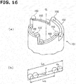
- FIG. 16(a) is a perspective view showing one of cam members 101 disclosed in the patent document 2.
- the cam member 101 includes four cam surfaces 102 extending in a helical shape in a circumferential direction.
- Each of the balls 103 is provided to one of the cam surfaces 102.
- the balls 103 are arranged to be moved relative to the cam surfaces 102 along arrows in FIG. 16(a) in ranges of the circumferential strokes of these arrows, and thereby to serve for a smooth relative rotation between cam members, and a generation of the thrust.
- the movable stroke L BS of the plurality of (n) balls 103 are represented by following equation where a diameter of this ball 103 is d b , and an entire circumferential length of the cam surface 102 is L C1 .
- the movable stroke L BS of the ball 103 is decreased as the number of the balls is increased.
- L BS L C 1 ⁇ N ⁇ d b
- the relative rotation amount of the two cam members is restricted by the movable stroke L BS of the ball 103. Accordingly, for ensuring the relative axial movement amounts of the two cam members, it is necessary to decrease the number of the balls 103, to increase the helical radius of the helical cam surface 102, or to increase an inclination angle (an inclination angle with respect to a circumferential surface perpendicular to a center axis CL) ⁇ of the helical cam surface 102.
- an object of the present invention to provide a torque cam device for an automatic transmission which is devised to solve the above-described problems, to arrange a plurality of balls of between cam surfaces, to ensure a length of each of the cam surfaces without increasing inclination angles of the cam surfaces, to generate large thrust, and to sufficiently ensure a ratio coverage of the automatic transmission.
- the electric vehicle according to the present invention (hereinafter, referred to merely as a vehicle) is an electric vehicle (called also as EV) which travels to use only an electric motor as a driving source.
- the electric vehicle according to the present invention does not include a hybrid vehicle which travels by selectively using the electric motor and an internal combustion engine as a driving source.
- the present automatic transmission is disposed between the electric motor and driving wheels of the thus-constructed vehicle.
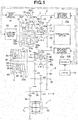
- this driving system unit includes a main electric motor (called merely also as an electric motor) 1 which is a driving source of the vehicle; an automatic transmission 2 including a transmission input shaft (hereinafter, referred to as an input shaft) 2A which is integrally connected to an output shaft of the main electric motor 1; a speed reduction mechanism 6 connected to the automatic transmission 2; and a differential mechanism 7 connected to the speed reduction mechanism 6.
- Wheel shafts 7L and 7R are connected to left and right side gears of the differential mechanism 7.
- Driving wheels (not shown) are connected, respectively, to the wheel shafts 7L and 7R.
- the automatic transmission 2 is a transmission which is constituted by adding a direct connection gear mechanism 20 to a belt type continuously variable transmission mechanism (CVT) with an auxiliary transmission mechanism.
- the automatic transmission 2 includes a belt type continuously variable transmission mechanism (hereinafter, referred to also as a variator) 3 which includes a belt 37 for transmitting a power, and which includes a primary pulley (input portion) 30P that is disposed to be rotated relative to the input shaft 2A; a constantly meshed parallel shaft type gear transmission mechanism (hereinafter, referred to also as the auxiliary transmission mechanism) 4 which is connected to a rotation shaft 36 of a secondary pulley (output portion) 30S of this variator 3; and the direct connection gear mechanism 20 which is arranged to directly connect the input shaft 2A and the speed reduction mechanism 6 to avoid the variator 3 and the auxiliary transmission mechanism 4.
- the variator 3 includes the primary pulley 30P including a fixed pulley 31 including a rotation shaft 33, and the movable pulley 32; a secondary pulley 30S including a fixed pulley 34 including the rotation shaft (output shaft) 36, and a movable pulley 35; and a belt 37 which is wound around V grooves of the primary pulley 30P and the secondary pulley 30S.
- the rotation shaft 33 of the fixed pulley 31 of the primary pulley 30P is disposed to be rotated relative to the input shaft 2A.
- FIG. 1 shows the primary pulley (the pulley device) 30P, the secondary pulley (the pulley device) 30S, and the belt 37 of the variator 3 in states where a transmission gear ratio is a low side and a high side.
- the state of the low side is shown in half portions of respective outer sides (on a side on which the pulleys are apart from each other) of the primary pulley 30P and the secondary pulley 30S.
- the high side state is shown in half portions of respective inner sides (on a side on which the pulleys are near each other) of the primary pulley 30P and the secondary pulley 30S.
- the state of the low side of the belt 37 is schematically shown by a solid line.
- the state of the high side of the belt 37 is shown schematically shown by a two dot chain line. Besides, the high state shown by the two dot chain line shows only a position relationship of the radial direction of the pulley and the belt. An actual belt position does not appears in the half portion of the inner side of the pulley.
- An electric actuator 80A and a mechanical reaction force mechanism perform an adjustment of the transmission gear ratio, and an adjustment of a pulley thrust (referred to merely as a thrust), that is, an adjustment of a belt clamping force, by varying belt winding radii of the primary pulley 30P and the secondary pulley 30S of this variator 3.
- a torque cam mechanism is used as the mechanical reaction force mechanism.
- This torque cam mechanism is constituted by a pair of cam members which have annular shapes, and which have cam surfaces that are positioned at end portions, and that are inclined in helical (spiral) shapes. These torque cam mechanisms are coaxially disposed so that the respective cam surfaces are slidably abutted on each other.
- the pair of the cam members are arranged to be moved closer to or away from each other in the axial direction in accordance with the relative rotation of the pair of the cam members, so that an entire length of the pair of the cam members is varied.
- the torque cam mechanism is arranged to adjust the thrust of the rotation member (pulleys 30P and 30S) which is pressed and abutted on one of the cam members.
- the torque cam mechanisms are used as the mechanical reaction force mechanism in both of the primary pulley 30P and the secondary pulley 30S.
- the ball torque cam mechanisms of the both pulleys are acted as the reaction forces of the forces which are generated by the belt 37 to push the primary pulley 30P and the secondary pulley 30S (the force that separates the pulleys).
- the thrusts according to the transmitting torques of the belt 37 are generated in the both pulleys 30P and 30S without using hydraulic pressure and so on.
- the primary pulley 30P is provided with the electric actuator 80A which actively drives to rotate one of the pair of the cam members.
- the primary pulley 30P is constituted so as to adjust the groove width of the V groove of the primary pulley 30P by varying the entire length of the pair of the cam members.
- the respective torque cam mechanisms employ ball torque cam mechanisms in which slidably abutting portions of the respective cam surfaces are point contacts through the balls.
- the primary pulley 30P is provided with by the torque cam mechanism which is the mechanical reaction force mechanism, and the electric actuator 80A arranged to drive to rotate one of the pair of the cam members.
- the torque cam mechanism and the electric actuator 80A are arranged to vary the entire length of the pair of the cam members, to adjust the groove width of the V groove of the primary pulley 30P, and thereby to adjust the transmission gear ratio.
- the torque cam mechanism and the electric actuator 80A are arranged to adjust the belt clamping force by adjusting the thrust of the pulley 30P. Accordingly, the mechanism constituted by the electric actuator 80A and the torque cam mechanism of the primary pulley 30P is also referred to as a shift mechanism 8.
- the torque cam mechanism of the secondary pulley 30S is also referred to as a thrust generating mechanism 9 since the torque cam mechanism of the secondary pulley 30S generates the thrust of the secondary pulley 30S. Details of these shift mechanism 8 and the thrust generating mechanism 9 will be illustrated later.
- the auxiliary transmission mechanism 4 has a plurality of gear stages (shift stages) (in this case, two stages of the High and the Low).
- the auxiliary transmission mechanism 4 includes gears 41 and 42 which are provided to be rotated relative to a rotation shaft 43 which is integral coaxially with the rotation shaft 36 of the secondary pulley 30S of the variator 3; and gears 44 and 45 which are disposed and fixed on a rotation shaft 46 parallel to the rotation shaft 43 so as to rotate as a unit with the rotation shaft 46.
- the gear 41 and the gear 44 are constantly engaged with each other.
- the gear 41 and the gear 44 constitute a second speed (High) gear stage.
- the gear 42 and the gear 45 are constantly engaged with each other.
- the gear 42 and the gear 45 constitute a first speed (Low) gear stage.
- the auxiliary transmission mechanism 4 is provided with an engagement clutch mechanism 5B of three position type which is arranged to selectively switch the second speed gear stage and the first speed gear stage.
- the engagement clutch mechanism 5B includes a clutch hub 54 arranged to rotate as a unit with the rotation shaft 43; a sleeve 55 having an internal teeth 55a which is spline-engaged with an external teeth 54a provided to the clutch hub 54; a shift folk 56 arranged to move the sleeve 55 in a shift direction (an axial direction); and a switching electric actuator 50B which is arranged to drive the shift folk 56.
- the gear 41 is provided with an external teeth 41a arranged to be engaged with the internal teeth 55a of the sleeve 55.
- the gear 42 is provided with an external teeth 42a arranged to be engaged with the internal teeth 55a of the sleeve 55.
- the sleeve 55 has respective positions of a neutral position (N), a second speed position (H) setting the second speed (High) gear stage, and a first speed position (L) setting the first speed (Low) gear stage.
- the sleeve 55 is driven to be slid among the respective positions by the shift folk 56.
- the sleeve 55 By moving the sleeve 55 toward the gear 41's side (that is, the second speed position) by driving the shift folk 56 by the electric actuator 50B, the internal teeth 55a of the sleeve 55 is engaged with the external teeth 41a of the gear 41. With this, the rotation shaft 43 and the gear 41 rotate as a unit with each other, so that the second speed gear stage is set.
- the power is transmitted from the rotation shaft 36 of the secondary pulley 30S of the variator 3 (that is, the rotation shaft 43) through the gear 41, the gear 44, and the rotation shaft 46 to the speed reduction mechanism 6.
- the sleeve 55 By moving the sleeve 55 toward the gear 42's side (that is, the first speed position) by driving the shift folk 56 by the electric actuator 50B, the internal teeth 55a of the sleeve 55 is engaged with the external teeth 42a of the gear 42. With this, the rotation shaft 43 and the gear 42 rotate as a unit with each other, so that the first speed gear stage is set.
- the power is transmitted from the rotation shaft 36 of the secondary pulley 30S of the variator 3 (that is, the rotation shaft 43) through the gear 42, the gear 45, and the rotation shaft 46 to the speed reduction mechanism 6.
- a rotation synchronous control described later is performed for smoothly engaging the internal teeth 55a of the sleeve 55 with the external teeth 41a of the gear 41 and the external teeth 42a of the gear 42. Accordingly, a synchronous mechanism is not needed at an engaging portion. There is not provided the synchronous mechanism.
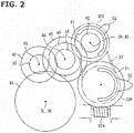
- the direct connection gear mechanism 20 includes an input gear (an input gear) 21 disposed to be rotated relative to the input shaft 2A. As shown in FIG. 2 , this input gear 21 is engaged and drivingly connected with one of the plurality of the shift gears of the auxiliary transmission mechanism (in this case, the gear 45 which is the output side gear of the first speed stage).
- teeth numbers of the input gear 21 and the gear 45 are set substantially identical to each other so that the transmission gear ratio becomes substantially 1.0.
- an engaging (meshing) clutch mechanism 5A of 3 position type For selectively using this direct connection gear mechanism 20 and the variator 3, there is provided an engaging (meshing) clutch mechanism 5A of 3 position type.
- the engaging clutch mechanism 5A has a configuration identical to the engaging clutch mechanism 5B.
- the engaging clutch mechanism 5A includes a clutch hub 51 arranged to rotate as a unit with the input shaft 2A; a sleeve 52 including an internal teeth 52a which is spline-engaged with an external teeth 51a provided to the clutch hub 51; a shift folk 53 arranged to move the sleeve 52 in a shift direction (an axial direction); and a switching electric actuator 50A arranged to drive the shift folk 53.
- the input gear 21 is provided with an external teeth 22 arranged to be engaged with the internal teeth 52a of the sleeve 52.
- the rotation shaft 33 of the fixed pulley 31 of the primary pulley 30P of the variator 3 is provided with an external teeth 38 which is arranged to be engaged with the internal teeth 52a of the sleeve 52.
- the sleeve 52 has respective positions of a neutral position (N), a CVT position (C) setting a power transmitting path passing through the variator 3, and a direct connection position (D) setting the power transmitting path passing through the direct connection gear mechanism 20.
- the sleeve 52 is driven to be slid among the respective positions by the shift folk 53.
- the internal teeth 52a of the sleeve 52 is engaged with the external teeth 22 of the input gear 21.
- the input shaft 2A and the input gear 21 rotate as a unit with each other, so that the power transmitting path passing through the direct connection gear mechanism 20 is set.
- a rotation synchronous control described later is performed for smoothly engaging the internal teeth 52a of the sleeve 52 with the external teeth 38 of the rotation shaft 33 and the external teeth 22 of the input gear 2. Accordingly, the synchronous mechanism is not needed at an engaging portion. There is not provided the synchronous mechanism.
- the both engaging clutch mechanisms 5A and 5B are not provided with the synchronous mechanism since the synchronous rotation control is performed as described above.
- the synchronous mechanism it is possible to obtain an effect to further promote the synchronism.
- the rotation synchronism control is not performed, the synchronous mechanism is needed.
- the speed reduction mechanism 6 includes a gear 61 disposed and fixed on the rotation shaft 46 of the auxiliary transmission mechanism 4 to rotate as a unit with the rotation shaft 46 of the auxiliary transmission mechanism 4; a gear 62 which is disposed and fixed on a rotation shaft 65 that is parallel to the rotation shaft 46 to rotate as a unit with the rotation shaft 65, and which is engaged with the gear 61; a gear 63 disposed and fixed on the rotation shaft 65 to rotate as a unit with the rotation shaft 65; and a gear 64 which is an input gear of the differential mechanism 7, and which is engaged with the gear 63.
- the speed is reduced between the gear 61 and the gear 62 in accordance with that gear ratio.
- the speed is reduced between the gear 63 and the gear 64 in accordance with that gear ratio.
- a thrust generating mechanism 9 which is one of the mechanical reaction force generating mechanisms, and which is provided to the secondary pulley 30S is illustrated. As described above, this thrust generating mechanism 9 employs the torque cam mechanism.
- the employed torque cam mechanism (the torque cam device) 90 is illustrated with reference to FIG. 5 to FIG. 9 .
- the torque cam mechanism 90 is an end cam.
- the torque cam mechanism 90 includes three cam members of a drive cam member 91 which is disposed and fixed on a back surface of the movable pulley 35; a driven cam member 93 which is disposed and fixed on the rotation shaft 36 of the fixed pulley 34, and which is adjacent to the drive cam member 91; and an intermediate (middle) cam member 92 which is disposed between the drive cam member 91 and the driven cam member 93, which is disposed coaxially with the drive cam member 91 and the driven cam member 93, and which is arranged to be rotated relative to the cam members 91 and 93.
- the drive cam member 91 drives the driven cam member 93 at the drive running (the drive travel) of the vehicle.
- the driven cam member 93 drives the drive cam member 91 at the coast running (the driven running, or the driven travel) of the vehicle.
- the torque cam mechanism 90 is constituted by three cam members.
- the intermediate cam member 92 is optional to the torque cam mechanism 90. Accordingly, the present invention is applicable to a torque cam mechanism which does not have the intermediate cam member 92.
- the drive cam member 91 is a cylindrical (or annular) member.
- the drive cam member 91 includes a first drive cam surface 91D which is an annular shape, and which is provided on one end side, and the other end side which is disposed and fixed on the back surface of the movable pulley 35.
- An entire annular circumference of the annular first drive cam surface 91D is equally divided into two.
- the respective first drive cam surfaces 91D have helical curved surfaces 91d according to predetermined cam angles.
- Connection portions 91J are formed, respectively, between the first drive cam surfaces 91D divided into two.
- connection portions 91J includes a connection surface (first connection surface) 91j which is formed into a stepped shape from an end portion of one of the helical curved surfaces 91d, and which extends in the axial direction; and a second connection surface 91k connecting an end portion of the connection surface 91j, and an end portion of the other of the helical curved surfaces 91d.
- connection surface 91j is formed in an axial direction (a direction parallel to the rotation axis) along the rotation axis of the drive cam member 91.
- Each of the second connection surfaces 91k is a surface perpendicular to the axial direction of drive cam member 91.
- the driven cam member 93 has a shape which is symmetrical to the drive cam member 91, and which is obtained by inverting (reversing) the perspective view of FIG. 6(b) .
- the driven cam member 93 is explained by using the perspective view of FIG. 6(b) .
- the driven cam member 93 includes a first driven cam surface 93C which is an annular shape, and which is provided on one end side, and the other end side fixed on the rotation shaft 36. An entire annular circumference of the annular first driven cam surface 93C is equally divided into two.
- the respective first driven cam surfaces 93C have helical curved surfaces 93c according to predetermined cam angles. Connection portions 93J are formed, respectively, between the first driven cam surfaces 93C equally divided into two.
- connection portions 93J includes a connection surface (first connection surface) 93j which is formed into a stepped shape from an end portion of one of the helical curved surfaces 93c, and which extends in the axial direction; and a second connection surface 93k connecting an end portion of the connection surface 93j, and an end portion of the other the helical curved surfaces 93c.
- Each of the connection surface 93j is formed in an axial line direction (a direction parallel to the rotation axis) along the rotation axis of the driven cam member 93.
- connection surfaces 93j is formed in the axial direction of the driven cam member 93.
- Each of the second connection surface 93k is a surface perpendicular to the axial direction of the driven cam member 93.
- the intermediate cam member 92 is a cylindrical (or annular) member.
- the intermediate cam member 92 includes a second driven cam surface 92D which is an annular shape, which is positioned on one end side, and which confronts the first drive cam surface 91D of the drive cam member 91; and a second drive cam surface 92C which is an annular shape, which is positioned on the other end side, and which confronts the first driven cam surface 93C of the driven cam member 93.
- the intermediate cam member 92 serves as a driven cam member with respect to the drive cam member 91.
- the intermediate cam member 92 serves as a drive cam member with respect to the driven cam member 93. As shown in FIG.
- connection portion 92J includes a connection surface (first connection surface) 92j which is formed in a stepped shape from an end portion of one of the helical curved surfaces 92d, and which extends in the axial direction; and a second connection surface 92k connecting an end portion of the connection surface 92j and an end portion the other of the helical curved surfaces 92d.
- connection surfaces 92j is also formed in the axial direction of the intermediate cam member 92.
- Each of the second connection surfaces 92k is a surface perpendicular to the axial direction.
- An annular second drive cam surface 92C has a shape which is symmetrical to the second driven cam surface 92D, and which is obtained by inverting the perspective view of FIG. 6(a) .
- An entire annular circumference of the second driven cam surface 92C is equally divided into two.
- the respective first driven cam surfaces 92C have helical curved surfaces 92c according to predetermined cam angles.
- Connection portions 92J are formed, respectively, between the first driven cam surfaces 92C equally divided into two.
- connection portions 92J includes a first connection surface 92j which is formed into a stepped shape from an end portion of one of the helical curved surfaces 92d, and which extends in the axial direction; and a second connection surface 92k connecting an end portion of the first connection surface 92j, and an end portion of the other of the helical curved surfaces 92d.
- Each of the first connection surface connection surfaces 92j is formed in an axial direction of the intermediate cam member 92.
- Each of the second connection surfaces 92k is a surface perpendicular to the axial direction of the intermediate cam member 92.
- the helical curved surfaces 91d and 92d of the first drive cam surface 91D and the second driven cam surface 92D are helical shapes of the right-hand screws
- the helical curved surfaces of the first driven cam surface 93C and the second drive cam surface 92C are helical shapes of the left-handed screws.
- the second driven cam surface 92D and the second drive cam surface 92C of the intermediate cam member 92 are formed to have a phase shift in the rotation direction. That is, the first connection surface 92j connecting the two second driven cam surfaces 92D, and the first connection surfaces 92j connecting the two second drive cam surfaces 92C are disposed and formed so that the phases are deviated (shifted) from each other in the rotation direction.
- the phase shift of the cam surfaces 92D and 92C can be at most 90 degrees. With this, it is possible to decrease the axial length of the intermediate cam member 92.
- the second driven cam surface 92D of the intermediate cam member 92 is arranged to be abutted on the first drive cam surface 91D of the drive cam member 91.
- the second drive cam surface 92C of the intermediate cam member 92 is arranged to be abutted on the first driven cam surface 93C of the driven cam member 93.
- the balls (steel balls) 95 are disposed, respectively, between the both drive cam surfaces 91D and 92D, and between the both driven cam surfaces 93C and 92C.
- the torque cam mechanism 90 is constituted as a ball torque cam device.
- the helical curved surfaces of the first drive cam surface 91D of the drive cam member 91, the second driven cam surface 92D and the second drive cam surface 92C of the intermediate cam member 92, and the first driven cam surface 93C of the driven cam member 93 include, respectively, grooves (guide grooves) 91g, 92G, and 93g which have arc sections, and which receive the balls 95. With this, portions between the respective drive cam surfaces 91D and 92C, between the driven cam surfaces 93D and 92C are smoothly slid by point contacts by the balls 95.
- each of the grooves 92G of the second drive cam surface 92D and the second drive cam surface 92C of the intermediate cam member 92 is a guide groove (deep groove) which receives a portion of each of the balls 95 which is larger than a half portion of the each of the balls 95.
- Each of the grooves 91g and 93g of the first drive cam surface 91D of the drive cam member 91 and the first driven cam surface 93C of the driven cam member 93 is a shallow groove (in this case, a partially arc section) on which protruding top portions of the balls 95 received within one of the grooves 92G is slidably abutted.
- each of the grooves 92G of the intermediate cam member 92 incudes helical groove portions 92g each formed into a helical shape along one of the helical curved surfaces 92d and 92c of the second driven cam surface 92D and the second drive cam surface 92C of the intermediate cam member 92; and connection groove portions 92m each of which is formed between these helical groove portions 92g, and each of which smoothly connects the helical groove portions 92g.
- Each of the connection groove portions 92m is formed into a partially helical shape inclined in a direction opposite to the helical groove portion 92g in the circumferential direction.
- connection groove portions 92m and one of the helical groove portions 92g are connected by a smooth curve. Accordingly, the groove 92G is continuous around the entire circumference by the helical groove portions 92g and the connection groove portions 92m. The groove 92G is arranged to guide the movement of the ball 95 around the entire circumference.
- the plurality of the balls 95 are received to be rolled within the groove 92G while the balls 95 are slidably contacted with each other in a series state. Accordingly, even in a case where the torque transmitting direction between the drive cam member 91 and the driven cam member 93 are switched like the coast traveling, that is, even in a case where the drive actuation and the driven actuation of the cam members 91 and 93 are switched, the balls 95 within the groove 92G are difficult to be influenced by this switching. Beside, a lubricant oil is supplied into the groove 92G, so that the rolling movements of the balls 95 within the groove 92G are extremely smoothly performed.
- the groove 92G is formed into a partially circular shape having a sectional area greater than that of a semicircle.
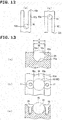
- the groove 92G is arranged to hold the balls 95, and to restrict the detachment (separation) of the balls 95. That is, as shown in FIG. 13 , the groove 92G includes an opening portion 98 which is formed on the helical groove portion 92g, and from which a part of each of the balls 95 can protrude from the helical curved surface 92d.
- the groove 92G receives a portion greater than the half portion (lower half portion in FIG. 13 ) of the ball 95.
- the opening portion 98 includes overhang portions 98a and 98a which are located at both edge portions of the opening portion 98, and which confront each other.
- a length between the overhang portions 98a and 98a, that is, an opening width w of the opening portion 98 is smaller than an outside diameter d of each of the balls 95.
- the cross sectional area of the helical groove portion 92g is formed into a partially circular shape having an inside diameter slightly greater than an outside diameter of the outside diameter d of each of the balls 95.
- an insertion diameter increasing portion 96 is formed in a portion of the opening portion 98, for inserting the balls 9 into the groove 92G of the opening portion 98 smaller than the outside diameter of each of the balls 95.
- the insertion diameter increasing portion 96 has a diameter greater than the outside diameter d of each of the balls 95. With this, it is possible to insert the balls 9 from the insertion diameter increasing portion 96 into the groove 92G.
- This insertion diameter increasing portion 96 includes a detachment (separation) preventing portion arranged to prevent the detachment (separation) of the inserted balls 95 from the groove 92G.
- the detachment preventing portion in this embodiment is screw members 99 inserted to close the diameter increasing portion of the insertion diameter increasing portion 96. That is, screw holes 97 are processed on both side portions of the insertion diameter increasing portion 96. After all of the balls 95 are inserted, the screw members 99 are tightened to the respective screw holes 97.
- Each of head portions of the screw members 99 includes a portion formed into the same sectional shape as the overhang portions 98a.
- the portion of the head portion of the screw member 99 becomes the same sectional shapes as the overhang portions 98a and 98a in the section of the insertion diameter increasing portion 96. It prevents the detachment (separation) of the balls 95 after the insertion from the inside 92G. Moreover, it does not interrupt the smooth rolling movements of the balls 95 within the groove 92G.
- the detachment preventing portion is not limited to the screw members 99.
- the cam surface 92d at the insertion diameter increasing portion 96 is formed to have a large thickness in an outward direction (in the upward direction of FIG. 13(a) ). After the insertion of the all of the balls 95, this large thickness portion may be caulked from the outside so as to have the same shape as the overhang portions 98a.
- the insertion diameter increasing portion 96 is formed at a portion of the helical curved surface 92d which has an axially protruding amount equal to or smaller than half. That is, each of the helical curved surfaces 92d protrudes in the axial direction in accordance with the phase angle.
- a portion in which the axially protruding amount is equal to or smaller than a half of an entire protruding amount is referred to as a valley side of the helical curved surface 92d.
- a portion in which the axially protruding amount is greater than the half of the entire protruding amount is referred to as a mountain side of the helical curved surface 92d.
- the insertion diameter increasing portion 96 is formed on this valley side (cf. FIG. 10 ).
- the slidably abutting region becomes long with respect to the cam surfaces 91D and 93C of the confronting cam members 91 and 93, so that more balls 95 are abutted on the both cam surfaces 91D and 92D or 92C and 93C. Accordingly, the stress is dispersed at the portion (a valley portion) on the valley side of the helical curved surface 92d. With this, it is possible to relieve (decrease) the stress added at the insertion diameter increasing portion 96 and a portion around the insertion diameter increasing portion 96 which are easy to cause the stress concentration, and thereby to improve the durability.
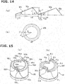
- FIG. 14(a) is a deployed view schematically showing an inclination state of the groove 92G.
- FIG. 14(b) is a plan view showing the groove 92G.
- a cam angle ⁇ shown in FIG. 14(a) is as follows, where a cam groove center radius is R [cf. FIG. 14(a) ], a necessary stroke of the cam mechanism is L, and a circulation cam return angle of the connection groove portion 92 shown in FIG. 14(a) is ⁇ ', when it is presumed that the entire of the helical groove portion 92g of the groove 92G serves for (contributes to) the stroke of the cam mechanism.
- a physical lower limit ⁇ min of ⁇ is represented by a follow equation (a).
- ⁇ min L ⁇ sin ⁇ ⁇ cos ⁇ ⁇ 360 / 2 ⁇ ⁇ ⁇ R
- ⁇ minr L ⁇ sin ⁇ ⁇ cos ⁇ ⁇ 3 ⁇ 360 / 2 ⁇ ⁇ ⁇ R
- the upper limit ⁇ max 2 ⁇ ⁇ ⁇ R / n ⁇ L / tan ⁇ ' ) ⁇ 360 / 4 ⁇ ⁇ ⁇ R where n is a number of the cam ridges (profiles).
- a range (deg) of ⁇ is represented by a following equation (d). ⁇ minr ⁇ ⁇ ⁇ ⁇ max
- the insertion diameter increasing portion 96 is positioned in this range, it is possible to surely prevent the interference of the tools at the downward motion on the lower limit side, to suppress the concentration of the stress to the members around the insertion opening on the upper limit side, and thereby to improve the durability.
- the length which is approximately 3 times longer than the physical lower limit ⁇ min is set to the practical lower limit ⁇ minr of ⁇ (the lower limit value for preventing the interference of the tools).
- the lower limit ⁇ minr is not limited to this.
- the lower limit ⁇ minr may be set by adding a predetermined amount based on an insertion region of the tools to the lower limit ⁇ min ⁇
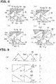
- the first drive cam surface 91D of the drive cam member 91 and the second driven cam surface 92D of the intermediate cam member 92 are meshed with each other, and the first driven cam surface 93C of the driven cam member 93 and the second drive cam surface 92C of the intermediate cam member 92 are meshed with each other.
- the total axial length of the drive cam member 91, the intermediate cam member 92, and the driven cam member 93 that is, the total length of the torque cam mechanism 90 becomes minimum.
- the groove width of the V groove of the secondary pulley 30S becomes maximum, so that the transmission gear ratio of the variator 3 becomes highest.
- the belt clamping force of the secondary pulley 30S becomes deficient, so that the fixed pulley 34 of the secondary pulley 30S is slid with respect to the belt 37.
- the movable pulley 35 arranged to be rotated relative to the rotation shaft 36 is moved to follow the belt 37. Accordingly, the phase delay of the fixed pulley 34 with respect to the movable pulley 35 is generated.
- the drive cam member 91 fixed to the movable pulley 35 is relatively rotated to antecede (precede) the intermediate cam member 92 and the driven cam member 93 fixed to the fixed pulley 34 while sliding the portions between the drive cam surface 91D and the driven cam surface 92D through the balls 95, as shown FIG. 7(b) , and moved to be separated from the driven cam member 93 and the intermediate cam member 92 in the axial direction so that the movable pulley 35 is moved closer to the fixed pulley 34. Consequently, the groove width of the V groove of the secondary pulley 30S is decreased, so that the thrust of the pulley 30S is increased. Therefore, the belt clamping force is increased, so that the slippage of the fixed pulley 34 is dissolved.
- the driven cam member 93 fixed to the fixed pulley 34 is relatively rotated to antecede (precede) the intermediate cam member 92 and the drive cam member 91 fixed to the movable pulley 35 while sliding the portions between the driven cam surface 93C and the drive cam surface 92C through the balls 95, as shown in FIG. 7(c) , and moved to be separated from the drive cam member 91 and the intermediate cam member 92 in the axial direction so that the movable pulley 35 is moved closer to the fixed pulley 34.
- the groove width of the V groove of the secondary pulley 30S is decreased, so that the thrust of the pulley 30S is increased. Accordingly, the belt clamping force is increased, so that the slippage of the fixed pulley 34 is dissolved.
- a coil spring 94 arranged to urge the movable pulley 35 in a direction to be closer to the fixed pulley 34, so as to prevent the belt slippage and to surely clamp the belt 37 in the initial driving state such as the start of the vehicle.
- the shift mechanism 8 provided to the primary pulley 30P is constituted by the electric actuator 80A and the mechanical reaction force mechanism 80B.
- the torque cam mechanism is employed as the mechanical reaction force mechanism 80B.
- the torque cam mechanism employed in the mechanical reaction force mechanism 80B is disposed behind the movable pulley 32 of the primary pulley 30P.
- the torque cam mechanism includes a pair of cam members 83 and 84 coaxially disposed on the rotation shaft 33.
- the cam members 83 and 84 include, respectively, helical cam surfaces 83a and 84a which are inclined with respect to a direction perpendicular to the rotation shaft 33.
- the pair of the cam members 83 and 84 are disposed so that the respective cam surfaces 83a and 84a are abutted on each other.
- the torque cam mechanism employs the ball torque cam mechanism in which balls (steel balls 85) is disposed between the cam surfaces 83a and 84a that are slidalby abutted on each other, and in which the sildably abutting portions are the point contacts by the balls 85.
- the cam surfaces 83a and 84a are smoothly slid with each other.
- the cam member 83 and the cam member 84 can be rotated relative to the rotation shaft 33.
- the cam member 83 and the cam member 84 are disposed coaxially with the rotation shaft 33 independently of the fixed pulley 31 and the movable pulley 32 of the primary pulley 30P. That is, the cam members 83 and 84 are not rotated even when the primary pulley 30P is rotated.
- the cam member 84 is a fixed cam member which is fixed in the rotation direction and in the axial direction.
- the cam member 83 is a movable cam member which is arranged to be rotated relative to the cam member 84, and to be moved in the axial direction.
- the movable cam member 83 includes a slidably abutting surface 83b which is positioned on a side opposite to the cam surface 83a, and which is slidably abutted on a back surface 32a of the movable pulley 32 through a thrust bearing and so on.
- the electric actuator 80A rotationally drives the movable cam member 83 so that the cam surface 83a of the movable cam member 83 is rotated relative to the cam surface 84a of the fixed cam member 84. With this, the electric actuator 80A moves the movable cam member 83 in the axial direction of the rotation shaft 33 along the inclinations of the cam surface 83a and the cam surface 84a. With this, the electric actuator 80A moves the movable pulley 32 in the axial direction of the rotation shaft 33, so as to adjust the groove width of the V groove of the primary pulley 30P.
- the electric actuator 80A includes a worm gear mechanism 82 including a worm (screw gear, crossed helical gear) 82a, and a worm wheel (helical gear) 82b engaged with this worm 82a; and an electric motor 81 arranged to rotatably drive the worm 82a.
- the worm wheel 82b is disposed coaxially with the rotation shaft 33.
- the worm wheel 82b is connected with an outer circumference of the movable cam member 83 by serration so as to rotate as a unit with the movable cam member 83, and to allow the movement of the movable cam member 83 in the axial direction.
- the adjustment of the groove width of the V groove of the primary pulley 30P by the shift mechanism 8 is performed while receiving the thrust of the secondary pulley 30S which is generated by the thrust generating mechanism 9.
- the groove width of the V groove of the primary pulley 30P is decreased, the groove width of the V groove of the secondary pulley 30S which is connected through the belt is increased. Accordingly, it is opposed to the thrust by the thrust generating mechanism 9.
- the groove width of the V groove of the primary pulley 30P is increased, the groove width of the V groove of the secondary pulley 30S is decreased. Accordingly, the thrust by the thrust generating mechanism 9 is used.
- the electric motor 81 is actuated so as to separate the movable cam member 83 from the fixed cam member 84.
- the winding radius of the belt 37 with respect to the primary pulley 30P is increased. Consequently, the tension of the belt 37 is increased.
- the increase of the tension of the belt 37 is acted to decrease the winding radius of the belt 37 with respect to the secondary pulley 30S.
- the increase of the groove width of the V groove of the secondary pulley 30S is needed for the decrease of the winding radius of the belt 37 with respect to the secondary pulley 30S.
- the electric actuator 80A drives the movable cam member 83 to resist this thrust.
- the electric motor 81 is actuated so that the movable cam member 83 is moved closer to the fixed cam member 84.
- the winding radius of the belt 37 with respect to the primary pulley 30P is decreased, so that the tension of the belt 37 is decreased.
- the decrease of the tension of the belt 37 causes the slippage between the secondary pulley 30S and the belt 37.
- the movable pulley 35 of the secondary pulley 30S follows to the belt 37.
- the slippage of the fixed pulley 34 with respect to the belt 37 is generated.
- a torsion is generated between the fixed pulley 34 and the movable pulley 35.
- the thrust of the secondary pulley 30S is increased (strengthened) in accordance with this torsion between the fixed pulley 34 and the movable pulley 35.
- This variator 3 of the automatic transmission 2 is provided with an auxiliary electric motor 10 directly connected to the rotation shaft 33 of the primary pulley 30P.
- This auxiliary electric motor 10 rotationally drives the rotation shaft 33 during the switching operation by the engaging clutch mechanism 5a, so as to promote the rotation synchronism of the input side and the output side of one of the gear stages of the auxiliary transmission mechanism 4.
- this vehicle includes an EVECU 110 configured to totally control the electric vehicle; and a CVTECU 100 configured to control main parts of the automatic transmission (CVT with the auxiliary transmission mechanism) 2.
- Each of the ECUs is a computer constituted by memories (ROM and RAM), CPU and so on.
- the CVTECU 100 is configured to control the actuations of the electric motor 81 constituting the electric actuator 80A of the shift mechanism 8, and the switching electric actuators 50A and 50B, and so on, based on command or information from the EVECU 110, and information from other sensors and so on.
- the present embodiment is constituted as described above. Accordingly, it is possible to obtain following operations and effects.
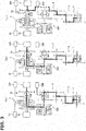
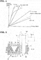
- the automatic transmission 2 is constituted by adding the auxiliary transmission mechanism (the constantly meshed parallel shaft type gear transmission mechanism) 4, and the direct connection gear mechanism 20 to the variator (the belt type continuously variable transmission mechanism) 3. Accordingly, the CVTECU 100 can select and use three main power transmitting modes shown in FIG. 3 by using, for example, a shift map shown in FIG. 4 .
- the CVT low mode in which the variator 3 is used and the auxiliary transmission mechanism is switched to the first speed (the Low) is selected, as shown in FIG. 3(a) .
- the CVT high mode in which the variator 3 is used and the auxiliary transmission mechanism 4 is switched to the second speed (the High) is selected, as shown in FIG. 3(b) .
- the auxiliary transmission mechanism 4 it is possible to travel in a wide range of the transmission gear ratio from a state (1st Low) in which the variator 3 is brought to the lowest in the CVT low mode where the auxiliary transmission mechanism 4 is brought to the first speed (the Low), to a state (2nd High) in which the variator 3 is brought to the highest in the CVT high mode where the auxiliary transmission mechanism 4 is brought to the second speed (the High), as shown in FIG. 4 .
- the width of the transmission gear ratio of the automatic transmission 2 it is possible to decrease the load of the electric motor 1 of the driving source. Accordingly, it is possible to decrease the size of the electric motor 1, and thereby to decrease the entire size of the power train. Moreover, it is possible to use the region in which the good efficiency of the electric motor 1 is obtained, and thereby to improve the efficiency of the power train. With this, it is possible to increase the cruising range (driving range) of the electric vehicle.
- the direct connection mechanism 20 when the vehicle travels on the highway and so on at the high speed, the direct connection mechanism 20 is used as shown in FIG. 3(b) . With this, it is possible to attain the power transmission by the gear having the high transmitting efficiency. Accordingly, it is possible to improve the energy efficiency for the above effects, and to increase the cruising range of the electric vehicle. Besides, in a case where the transmission gear ratio by the direct connection gear mechanism 20 is set to a value slightly higher than the transmission gear ratio of the second speed lowest as shown in a broken line of FIG. 4 , it is possible to decrease the load of the motor at the high speed traveling, and to contribute to the increase of the cruising range of the electric vehicle.
- the synchronous rotation is performed by using the electric motor 1 and the auxiliary electric motor 10. With this, it is possible to promote the synchronous rotation, and to decrease the shift time period. Moreover, it is possible to decrease the shift shock. Furthermore, it is possible to surely perform the adjustment of the synchronism by the synchronous rotation by the electric motor 1 and the auxiliary electric motor 10, and to decrease the cost of the device by omitting the synchronous mechanism and so on.
- the auxiliary transmission mechanism 4 when the auxiliary transmission mechanism 4 is switched between the first speed (the Low) and the second speed (the High) by the engaging clutch mechanism 5B, the rotation of the rotation shaft 43 of the auxiliary transmission mechanism 4 is synchronized with the rotation of the gear 41 or the gear 42.
- the electric motor 1 and the auxiliary electric motor 10 are actuated to be cooperated with each other. With this, it is possible to rapidly obtain the synchronism by overcoming the large inertia mass of the variator 3, and to decrease the shift time periods.
- the engaging clutch mechanism 5A switches a state in which the variator 3 is used, and a state in which the direct connection gear mechanism 20 is used, the input rotation member and the output rotation member of the engaging clutch mechanism 5A are brought to the synchronous rotation state. In this case, it is possible to use the electric motor 1 and the auxiliary electric motor 10.
- the auxiliary electric motor 10 merely uses for the synchronous rotation at the shift. Accordingly, it is possible to employ the small motor having the small output, and to suppress the increase of the cost of the device.
- the large torque is added to the power transmitting system for the amplification of the torque, on the more downstream side of the power transmitting path of the driving system unit of the vehicle.
- the auxiliary electric motor 10 is connected to the rotation shaft 33 of the primary pulley 30P on the relatively upstream side of the power transmitting path, it is easy to employ the small motor which has the small output, and which corresponds to the low torque.
- this auxiliary electric motor 10 is used for the torque assist for driving the vehicle.
- the motor having the suitable output is employed as the auxiliary electric motor 10.
- the both engaging clutch mechanisms 5A and 5B are brought to the neutral state. Then, the rotation of the electric motor 1 is controlled to be synchronized with the rotation of the input gear 21.
- the engaging clutch mechanism 5A being the neutral state is switched to the direct connection positon (D) so that the member on the input shaft 2A's side (the internal teeth 52a of the sleeve 52) and the member on the input gear 21's side (the external teeth 52a) are engaged with each other.
- the engaging clutch mechanism 5B is maintained to the neutral state during the direct driving state.
- the torque cam mechanism (the torque cam device) 90.
- the driving that is, at the power transmission from the drive cam member 91 to the driven cam member 93 (when the power is transmitted from the drive cam member 91 to the driven cam member 93)
- the first drive cam surface 91D of the drive cam member 91 and the second driven cam surface 92D of the intermediate cam member 92 are abutted on each other, so that the power is transmitted.
- the first driven cam surface 93C of the driven cam member 93 and the second drive cam surface 92C of the intermediate cam member 92 are abutted on each other, so that the power is transmitted.
- first drive cam surface 91D, second driven cam surface 92D, first driven cam surface 93C and the second drive cam surface 92C which have the annular shapes can be formed around the entire circumference of the annular shape. It is possible to ensure the length of the cam surface by the entire circumference.
- FIG. 9(a) is a schematic circumferential view in a case where the torque cam device is constituted without using the intermediate cam. As shown in FIG. 9(a) , the drive cam surface 192D and the driven cam surface 192c can only ensure the length of the cam surface only by the half of the entire circumference of the annular shape.
- FIG. 9(b) is a schematic circumference view in a case where a difference in height (corresponding to the cam stroke) of the cam surfaces of the torque cam mechanism 90 according to the present invention is set identical to that of FIG. 9(a) .
- the respective cam surfaces 91D and 93C (also the cam surfaces 92D and 92C (not shown)) can be formed around the entire annular circumferences. Accordingly, it is possible to substantially double the length of the cam surfaces. Consequently, the inclination angle ⁇ 2 of the cam surfaces can be set to a value smaller than the inclination angle ⁇ 1 of the case in which the intermediate cam is not used ( ⁇ 2 ⁇ 1) while ensuring the cam stroke amount. It is possible to increase the generated thrust.
- connection surfaces 91j, 92j, and 93j are formed, respectively, in directions along the rotation axis (in the direction parallel to the rotation axis). Accordingly, the torque cam mechanism 90 is rapidly actuated.
- the torque cam mechanism 90 is brought to the state where the power is transmitted from the drive cam member 91 toward the driven cam member 93, as shown in FIG. 8(a) .
- the first drive cam surface 91D of the drive cam member 91 presses the second driven cam surface 92D of the intermediate cam member 92 (cf. an arrow F1), so that the connection surface 92j of the intermediate cam member 92 is abutted on the connection surface 93j of the driven cam member 93.
- connection surfaces 92j and 93j are formed, respectively, in the directions along the rotational axes. Accordingly, a component force F2 is acted to the second driven cam surface 92D in the rotation axis direction along the connection surfaces 92j and 93j. With this, the intermediate cam member 92 is pressed toward the driven cam member 93, as shown in FIG. 8(b) . The second drive cam surface 92C of the intermediate cam member 92 is abutted on the first driven cam surface 93C of the driven cam member 93.
- the second driven cam surface 92D and the second drive cam surface 92C of the intermediate cam member 92 are formed to have the rotation shift (deviation) in the rotational direction. Accordingly, it is possible to avoid the positional interference of the cam surfaces 92D and 92C, and thereby to suppress the axial length of the intermediate cam member 92.
- the phase shift of the cam surfaces 92D and 92C is set to 90 degrees. Accordingly, it is possible to suppress the axial length of the intermediate cam member 92 at the maximum degree.
- the guide groove 92G arranged to guide the movements of the balls 95 is formed around the entire circumferences of the second driven cam surface 92D and the second drive cam surface 92C of the intermediate cam member 92. Accordingly, the plurality of the balls 95 can be disposed between the cam surfaces. Moreover, it is possible to ensure the lengths of the cam surfaces, without increasing the inclination angle of the cam surface. Consequently, it is possible to suppress the loads (load burdens) of the balls 95 and the cam surfaces 91D, 92D, 92C, and 93C. For example, in a case where it is used in the thrust generating mechanism of the shift mechanism of the belt type continuously variable transmission, it is possible to generate the large thrust, and to sufficiently ensure the ratio coverage, without increasing the size of the device.
- the guide groove 92G includes the helical groove portions 92g each formed in the helical shape along one of the helical curved surfaces 92d; and the connection groove portions 92m each of which is formed between the helical groove portions 92g, and which smoothly connects the helical groove portions 92g. Accordingly, the movements of the balls 95 are not restricted to decrease the sliding resistance (friction). With this, the balls 95 can be smoothly moved around the entire circumference.
- connection portions 91J, 92J, and 93J are formed between the equally divided helical curved surfaces 91d, 92d, 92c, and 93c of the cam surfaces 91D, 92D, 92C, and 93C.
- These connection portions 91J, 92J, and 93J include, respectively, the first connection surface 91j, 92, and 93j each extending in the axial direction from the end portion of one of the helical curved surfaces connected with each other; and the second connection surfaces 91k, 92k, and 93k each connecting one of the end portions of the first connection surfaces 91j, 92j, and 93j and the end portion of the other of the helical curved surfaces.
- Each of the second connection surfaces 91k, 92k, and 93k is a surface perpendicular to the axis direction. Accordingly, it is possible to decrease the axial lengths of the drive cam member 91, the intermediate cam member 92, and the driven cam member 93.
- the guide groove 92G includes the opening portion 98.
- the guide groove 92G receives the portion of each of the balls 95 which is greater than the half portion of the each ball 95 so that a part of the each ball 95 protrudes from the opening portion 98 in the outside direction.
- An opening width of the opening portion 98 is smaller than an outside diameter of each of the balls 95. Accordingly, the balls 95 are surely held within the guide groove 92G without being detached from the guide groove 92G.
- the insertion diameter increasing portion 96 is formed at a portion of the guide groove 92G.
- the insertion diameter increasing portion 96 has the increased diameter for inserting the balls 95 into the guide groove 92G.
- the screw members 97 are mounted to the insertion diameter increasing portion 96 to close the diameter increasing portion of the insertion diameter increasing portion 96.
- the screw members 97 are the detachment preventing portions arranged to prevent the detachment of the inserted balls 95 from the inside of the guide groove. Accordingly, the balls 95 are surely held within the guide groove 92G without being detached from the insertion diameter increasing portion 96.
- the insertion diameter increasing portion 96 is formed in the region of the above-described ⁇ , in particular, in the valley portion on the lower side of the half portion of the inclination surface of the cam. Accordingly, the balls 95 are constantly abutted by the multipoint contacts near the insertion diameter increasing portion 96. Consequently, the cam members 91, 92, and 93 can be accurately slid along the helical curved surfaces. For example, it is possible to suppress the concentration of the stress in a case of the one point contact at which the concentration of the stress is generated in the members around the one point contact by the generation of the inclinations of the cam members 91, 92, and 93 with respect to the axial direction. Therefore, it is possible to improve the durability.
- the torque cam mechanism 90 is constituted by three cam members 91,92, and 93.
- the middle cam member 92 is optional in the torque cam mechanism 90.
- the present invention is applicable to the torque cam mechanism which does not have the intermediate cam member 92.
- the torque cam mechanism 90 includes two cam members of a drive cam member 91 which is disposed and fixed on a back surface of the movable pulley 35; and a driven cam member 193 which is disposed and fixed on the rotation shaft 36 of the fixed pulley 34.
- the drive cam member 91 drives the driven cam member 193 at the drive running (the drive travel) of the vehicle.
- the driven cam member 193 drives the drive cam member 91 at the coast running (the driven running, or the driven travel) of the vehicle.
- the drive cam member 91 is identical to that of the first embodiment as shown in FIG. 15(b) . Accordingly, the explanations are omitted [cf. FIG. 6(b) ].
- the driven cam member 193 has a shape which is substantially symmetrical to the drive cam member 91.
- the driven cam member 193 includes a first driven cam surface 193D which is an annular shape, and which is provided on one end side, and the other end side fixed on the rotation shaft 36. An entire annular circumference of the annular first driven cam surface 193D is equally divided into two.
- the respective first driven cam surfaces 193D have helical curved surfaces 193d according to predetermined cam angles. Connection portions 193J are formed, respectively, between the driven cam surfaces 193D equally divided into two.
- connection portions 193J includes a connection surface (first connection surface) 193j which is formed into a stepped shape from an end portion of one of the helical curved surfaces 193d, and which extends in the axial direction; and a second connection surface 193k connecting an end portion of the connection surface 193j, and an end portion of the other the helical curved surfaces 193d.
- Each of the connection surface 193j is formed in an axial direction (a direction parallel to the rotation axis) along the rotation axis of the driven cam member 193.
- Each of the connection surfaces 193j is also formed in the axial line direction of the driven cam member 193.
- Each of the second connection surface 193k is a surface perpendicular to the axial direction of the driven cam member 193.
- the first driven cam surface 193D of the driven cam member 193 is arranged to be abutted on the first drive cam surface 91D of the drive cam member 91.
- the balls (steel balls) 95 are disposed between the both drive cam surfaces 91D and 193D.
- the torque cam mechanism 90 is constituted as a ball torque cam device.
- the helical curved surfaces of the first drive cam surface 91D of the drive cam member 91, and the driven cam surface 193D of the driven cam member 193 include, respectively, grooves (guide grooves) 91g and 193G which have arc sections, and which are arranged to guide the balls 95. With this, portions between the drive cam surface 91D and the driven cam surface 193D are smoothly slid by point contacts by the balls 95.
- the guide groove 193G of the driven cam surface 193D of the driven cam member 193 includes helical groove portions 193g and connection groove portions 193m, like the guide groove 92G of the second driven cam surface 92D of the intermediate cam member 92 in the embodiment.
- the guide groove 193G includes the opening portion (not shown), like the guide groove 92G.
- the guide groove 193G receives a portion of each of the balls 95 which is larger than a half portion of the each of the balls 95 so that a portion of the each of the balls 95 protrudes from the opening portion in the outside direction.
- An opening width of the opening portion is smaller than an outside diameter of each of the balls 95.
- an insertion diameter increasing portion (not shown) is formed in a portion of the opening portion of the guide groove 193G.
- the insertion diameter increasing portion 96 has an increased diameter for inserting the balls 95 into the groove 193G.
- An detachment preventing portion (for example, screw member 97) is mounted to the insertion diameter increasing portion.
- the detachment preventing portion is arranged to prevent the detachment (separation) of the inserted balls 95 from the inside of the guide groove.
- the insertion diameter increasing portion is formed in the range of the above-described angle ⁇ , in particular, in the valley portion on the lower side of the half of the inclination surface of the cam.
- the guide groove which is larger than that of the semicircle, and which is arranged to hold the balls 95 may be formed in the drive cam member 91.
- the present invention is not limited to the embodiment. It is possible to implement the present invention by appropriately varying the embodiment, or by partially employing the embodiment, as long as the it is not deviated from the gist of the present invention.
- the first drive cam surface 91D of the drive cam member 91 and the second driven cam surface 92D of the intermediate cam member 92 include, respectively, the guide grooves 91g and 93G arranged to continuously guide the balls 95 disposed between the first drive cam surface 91D of the drive cam member 91 and the second driven cam surface 92D of the intermediate cam member 92, in the entire circumference.
- the guide groove 93G of the second driven cam surface 92D of the intermediate cam member 92 is the guide groove receiving a portion of the each ball 95 which is greater than the half of the each ball 95.
- the guide groove 91g of the first drive cam surface 91D may be the guide groove receiving the portion of the each ball 95 which is greater than the half of the each ball 95.
- the second drive cam surface 92C of the intermediate cam member 92 and the first driven cam surface 93C of the driven cam member 93 include, respectively, the guide grooves 92G and 93G arranged to continuously guide the balls 95 disposed between the second drive cam surface 92C of the intermediate cam member 92 and the first driven cam surface 93C of the driven cam member 93, in the entire circumference.
- the guide groove 92G of the second drive cam surface 92D of the intermediate cam member 92 is the guide groove receiving a portion of each of the balls 95 which is greater than the half of the each ball 95.
- the guide groove 93g of the first driven cam surface 93C may be the guide groove receiving the portion of the each ball 95 which is greater than the half of the each ball 95.
- the drive cam surface 91D of the drive cam member 91 and the driven cam surface 93C of the driven cam member 93 include, respectively, the guide grooves 91g and 93G arranged to continuously guide the balls 95 disposed between the drive cam surface 91D of the drive cam member 91 and the driven cam surface 93C of the driven cam member 93, in the entire circumference.
- the guide groove 93G of the driven cam surface 93C of the driven cam member 93 is the guide groove receiving a portion of the each ball 95 which is greater than the half of the each ball 95.
- the guide groove 91g of the drive cam surface 91D may be the guide groove receiving the portion of the each ball 95 which is greater than the half of the each ball 95.
- the processing of the guide groove receiving the portion of the each ball 95 which is greater than the half of the each ball 95 needs special tools. Accordingly, the guide grooves receiving the portion of the each ball 95 which is greater than the half of the each ball 95 are formed on the both ends of the intermediate cam member 92 so that the processing which needs the special tools is convergently performed in the intermediate cam member 92, like the first embodiment. With this, it is possible to effectively perform the processing.
- the engaging clutch mechanisms 5A and 5B employ three positon type to simplify the configuration of the device.
- a combination of two engaging clutch mechanisms of two position type can be used to one or both of these engaging clutch mechanisms 5A and 5B.
- pulley devices 30P and 30S in which this torque cam device 90 is applied can be applied to the hybrid electric vehicle, and the vehicle driven by the engine, in addition to the electric vehicle.
- the mechanical reaction force mechanism is not limited to the end surface cam mechanism shown in the embodiment.
- the mechanism having the torque capacity can be constituted to the small size.
- the synchronism mechanism is not provided to the engaging portions of the engaging clutch mechanism 5A and 5B.
- the high accuracy of the rotation synchronism control is not needed. Accordingly, it is possible to operate the engagement of the clutch mechanisms 5A and5B before the completion of the rotation synchronism, and to decrease the time period needed for the shift.
- the guide groove 193G prevents the detachment of the balls 95.
- a holding device which is arranged to hold the balls, which is disposed between the cam surfaces for preventing the detachment of the balls, and which is a member different from the drive cam member and the driven cam member.
Landscapes
- Engineering & Computer Science (AREA)
- General Engineering & Computer Science (AREA)
- Mechanical Engineering (AREA)
- Transmissions By Endless Flexible Members (AREA)
- Transmission Devices (AREA)
Applications Claiming Priority (2)
| Application Number | Priority Date | Filing Date | Title |
|---|---|---|---|
| JP2015061657 | 2015-03-24 | ||
| PCT/JP2016/052856 WO2016152251A1 (ja) | 2015-03-24 | 2016-02-01 | 自動変速機のトルクカム装置 |
Publications (2)
| Publication Number | Publication Date |
|---|---|
| EP3276206A1 true EP3276206A1 (de) | 2018-01-31 |
| EP3276206A4 EP3276206A4 (de) | 2018-04-18 |
Family
ID=56978921
Family Applications (1)
| Application Number | Title | Priority Date | Filing Date |
|---|---|---|---|
| EP16768154.3A Withdrawn EP3276206A4 (de) | 2015-03-24 | 2016-02-01 | Drehmomentnockenvorrichtung mit automatikgetriebe |
Country Status (6)
| Country | Link |
|---|---|
| US (1) | US20180080534A1 (de) |
| EP (1) | EP3276206A4 (de) |
| JP (1) | JP6387180B2 (de) |
| KR (1) | KR20170129855A (de) |
| CN (1) | CN107429805A (de) |
| WO (1) | WO2016152251A1 (de) |
Cited By (1)
| Publication number | Priority date | Publication date | Assignee | Title |
|---|---|---|---|---|
| US12618457B2 (en) | 2023-10-17 | 2026-05-05 | Cvtech-Ibc Inc. | Double cam actuation system for CVT |
Families Citing this family (4)
| Publication number | Priority date | Publication date | Assignee | Title |
|---|---|---|---|---|
| KR102302520B1 (ko) * | 2017-03-17 | 2021-09-15 | (주)티아이에스 정보통신 | 기계식 디스크브레이크 |
| CN109764100A (zh) * | 2019-03-04 | 2019-05-17 | 赵彦斌 | 珠链式减速机构 |
| US11326676B2 (en) * | 2019-08-29 | 2022-05-10 | Kawasaki Jukogyo Kabushiki Kaisha | Power unit of utility vehicle |
| CN116409070B (zh) * | 2021-12-31 | 2023-09-15 | 浙江昕欣数码科技股份有限公司 | 一种数码印花机的导带装置 |
Family Cites Families (16)
| Publication number | Priority date | Publication date | Assignee | Title |
|---|---|---|---|---|
| US3786688A (en) * | 1973-04-16 | 1974-01-22 | Instrument Systems Corp | Variable ratio belt-type transmission having improved driven pulley |
| JPS5838055U (ja) * | 1981-09-08 | 1983-03-12 | 日産自動車株式会社 | 無段変速装置 |
| JPS6026844A (ja) * | 1983-07-25 | 1985-02-09 | Aisin Warner Ltd | Vベルト式無段変速機 |
| US4585429A (en) * | 1984-09-19 | 1986-04-29 | Yamaha Hatsudoki Kabushiki Kaisha | V-belt type continuously variable transmission |
| JPS6440755A (en) * | 1987-08-05 | 1989-02-13 | Bridgestone Cycle Co | Continuously variable transmission |
| US5720681A (en) * | 1996-03-18 | 1998-02-24 | Benson; Steven R. | Torque responsive actuation device |
| US6017285A (en) * | 1997-06-27 | 2000-01-25 | Koyo Seiko Co., Ltd. | Variable diameter pulley |
| CA2231491A1 (en) * | 1998-04-16 | 1999-10-16 | Rene Chamberland | Reversible driven pulley |
| CA2299882C (en) * | 1999-03-03 | 2006-09-19 | Kent Lee | Adjustable ramp helix |
| DE10025978C1 (de) * | 2000-05-25 | 2002-01-03 | Torrington Nadellager Gmbh | Axialstelltrieb, insbesondere zur Variatorbetätigung, Variator sowie CVT-Getriebe |
| DE10139119A1 (de) * | 2000-09-08 | 2002-03-21 | Luk Lamellen & Kupplungsbau | Drehmomentenfühler |
| CN1748099A (zh) * | 2003-02-10 | 2006-03-15 | Ntn株式会社 | 牵引驱动式无级变速器 |
| DE10333268B4 (de) * | 2003-07-21 | 2008-04-03 | Ab Skf | Vorrichtung zur Umwandlung einer Drehbewegung in eine translatorische Bewegung |
| JP2010053883A (ja) * | 2008-08-26 | 2010-03-11 | Ntn Corp | プーリユニット |
| EP2487386B1 (de) * | 2009-10-08 | 2017-04-19 | Yanmar Co., Ltd. | Stufenloses bandgetriebe |
| KR101772830B1 (ko) * | 2013-09-25 | 2017-08-29 | 쟈트코 가부시키가이샤 | 토크 캠 장치 및 벨트식 무단 변속 장치 |
-
2016
- 2016-02-01 KR KR1020177030010A patent/KR20170129855A/ko not_active Ceased
- 2016-02-01 EP EP16768154.3A patent/EP3276206A4/de not_active Withdrawn
- 2016-02-01 US US15/560,714 patent/US20180080534A1/en not_active Abandoned
- 2016-02-01 CN CN201680017852.9A patent/CN107429805A/zh active Pending
- 2016-02-01 WO PCT/JP2016/052856 patent/WO2016152251A1/ja not_active Ceased
- 2016-02-01 JP JP2017507552A patent/JP6387180B2/ja not_active Expired - Fee Related
Cited By (1)
| Publication number | Priority date | Publication date | Assignee | Title |
|---|---|---|---|---|
| US12618457B2 (en) | 2023-10-17 | 2026-05-05 | Cvtech-Ibc Inc. | Double cam actuation system for CVT |
Also Published As
| Publication number | Publication date |
|---|---|
| JPWO2016152251A1 (ja) | 2017-08-03 |
| CN107429805A (zh) | 2017-12-01 |
| JP6387180B2 (ja) | 2018-09-05 |
| WO2016152251A1 (ja) | 2016-09-29 |
| EP3276206A4 (de) | 2018-04-18 |
| KR20170129855A (ko) | 2017-11-27 |
| US20180080534A1 (en) | 2018-03-22 |
Similar Documents
| Publication | Publication Date | Title |
|---|---|---|
| US10054202B2 (en) | Torque cam device and belt-type continuously variable transmission | |
| CN112189100B (zh) | 逆向输入断开离合器以及促动器 | |
| US20180080534A1 (en) | Automatic-transmission torque cam device | |
| EP1071893B1 (de) | Reversible, angetriebene riemenscheibe | |
| EP4075005A1 (de) | Antriebskraftübertragungsroutenschaltvorrichtung und zweiganggetriebe | |
| US10088025B2 (en) | Automatic transmission for electric vehicle | |
| CN113864396A (zh) | 扭转阻尼器组件 | |
| JP6368674B2 (ja) | 自動変速機のトルクカム装置 | |
| JP2014025495A (ja) | 電気自動車用駆動装置 | |
| JP4275637B2 (ja) | ハイブリッド車両の駆動装置 | |
| JPWO2015045770A1 (ja) | 電気自動車用自動変速機 | |
| CN112534158B (zh) | 一种变速装置及其控制方法、转向系统及其控制方法 | |
| JP6791590B2 (ja) | トルクカム装置及び無段変速機 | |
| KR100460903B1 (ko) | 차량용 무단 변속기 | |
| CN109661529B (zh) | 自动变速器及自动变速器的控制方法 | |
| JP4685603B2 (ja) | 作業車両用変速装置 | |
| JP2019031995A (ja) | トルクカム装置及び無段変速機 | |
| JP6368670B2 (ja) | 無段変速機の変速機構 | |
| JP2009299716A (ja) | 無段変速機 | |
| JP2007139111A (ja) | ベルト式無段変速装置 | |
| JP2019002518A (ja) | トルクカム装置及びベルト式無段変速機 | |
| JP2007154995A (ja) | 作業車両用変速装置 | |
| JP2010001998A (ja) | 無段変速機 |
Legal Events
| Date | Code | Title | Description |
|---|---|---|---|
| PUAI | Public reference made under article 153(3) epc to a published international application that has entered the european phase |
Free format text: ORIGINAL CODE: 0009012 |
|
| 17P | Request for examination filed |
Effective date: 20171020 |
|
| AK | Designated contracting states |
Kind code of ref document: A1 Designated state(s): AL AT BE BG CH CY CZ DE DK EE ES FI FR GB GR HR HU IE IS IT LI LT LU LV MC MK MT NL NO PL PT RO RS SE SI SK SM TR |
|
| AX | Request for extension of the european patent |
Extension state: BA ME |
|
| A4 | Supplementary search report drawn up and despatched |
Effective date: 20180316 |
|
| RIC1 | Information provided on ipc code assigned before grant |
Ipc: F16H 25/18 20060101AFI20180312BHEP Ipc: F16H 55/56 20060101ALI20180312BHEP |
|
| DAV | Request for validation of the european patent (deleted) | ||
| DAX | Request for extension of the european patent (deleted) | ||
| 17Q | First examination report despatched |
Effective date: 20190715 |
|
| STAA | Information on the status of an ep patent application or granted ep patent |
Free format text: STATUS: THE APPLICATION HAS BEEN WITHDRAWN |
|
| 18W | Application withdrawn |
Effective date: 20200428 |