EP3276285A1 - Dispositif de soupape pour un conduit de distribution à cubes de glace dans un réfrigérateur - Google Patents
Dispositif de soupape pour un conduit de distribution à cubes de glace dans un réfrigérateur Download PDFInfo
- Publication number
- EP3276285A1 EP3276285A1 EP17182476.6A EP17182476A EP3276285A1 EP 3276285 A1 EP3276285 A1 EP 3276285A1 EP 17182476 A EP17182476 A EP 17182476A EP 3276285 A1 EP3276285 A1 EP 3276285A1
- Authority
- EP
- European Patent Office
- Prior art keywords
- obturator
- valve device
- bearing structure
- connecting rod
- shape
- Prior art date
- Legal status (The legal status is an assumption and is not a legal conclusion. Google has not performed a legal analysis and makes no representation as to the accuracy of the status listed.)
- Granted
Links
Images




Classifications
-
- F—MECHANICAL ENGINEERING; LIGHTING; HEATING; WEAPONS; BLASTING
- F25—REFRIGERATION OR COOLING; COMBINED HEATING AND REFRIGERATION SYSTEMS; HEAT PUMP SYSTEMS; MANUFACTURE OR STORAGE OF ICE; LIQUEFACTION SOLIDIFICATION OF GASES
- F25C—PRODUCING, WORKING OR HANDLING ICE
- F25C5/00—Working or handling ice
- F25C5/20—Distributing ice
- F25C5/22—Distributing ice particularly adapted for household refrigerators
-
- F—MECHANICAL ENGINEERING; LIGHTING; HEATING; WEAPONS; BLASTING
- F16—ENGINEERING ELEMENTS AND UNITS; GENERAL MEASURES FOR PRODUCING AND MAINTAINING EFFECTIVE FUNCTIONING OF MACHINES OR INSTALLATIONS; THERMAL INSULATION IN GENERAL
- F16K—VALVES; TAPS; COCKS; ACTUATING-FLOATS; DEVICES FOR VENTING OR AERATING
- F16K31/00—Actuating devices; Operating means; Releasing devices
- F16K31/02—Actuating devices; Operating means; Releasing devices electric; magnetic
- F16K31/025—Actuating devices; Operating means; Releasing devices electric; magnetic actuated by thermo-electric means
-
- E—FIXED CONSTRUCTIONS
- E05—LOCKS; KEYS; WINDOW OR DOOR FITTINGS; SAFES
- E05F—DEVICES FOR MOVING WINGS INTO OPEN OR CLOSED POSITION; CHECKS FOR WINGS; WING FITTINGS NOT OTHERWISE PROVIDED FOR, CONCERNED WITH THE FUNCTIONING OF THE WING
- E05F15/00—Power-operated mechanisms for wings
- E05F15/60—Power-operated mechanisms for wings using electrical actuators
-
- F—MECHANICAL ENGINEERING; LIGHTING; HEATING; WEAPONS; BLASTING
- F03—MACHINES OR ENGINES FOR LIQUIDS; WIND, SPRING, OR WEIGHT MOTORS; PRODUCING MECHANICAL POWER OR A REACTIVE PROPULSIVE THRUST, NOT OTHERWISE PROVIDED FOR
- F03G—SPRING, WEIGHT, INERTIA OR LIKE MOTORS; MECHANICAL-POWER PRODUCING DEVICES OR MECHANISMS, NOT OTHERWISE PROVIDED FOR OR USING ENERGY SOURCES NOT OTHERWISE PROVIDED FOR
- F03G7/00—Mechanical-power-producing mechanisms, not otherwise provided for or using energy sources not otherwise provided for
- F03G7/06—Mechanical-power-producing mechanisms, not otherwise provided for or using energy sources not otherwise provided for using expansion or contraction of bodies due to heating, cooling, moistening, drying or the like
- F03G7/061—Mechanical-power-producing mechanisms, not otherwise provided for or using energy sources not otherwise provided for using expansion or contraction of bodies due to heating, cooling, moistening, drying or the like characterised by the actuating element
- F03G7/0614—Mechanical-power-producing mechanisms, not otherwise provided for or using energy sources not otherwise provided for using expansion or contraction of bodies due to heating, cooling, moistening, drying or the like characterised by the actuating element using shape memory elements
- F03G7/06143—Wires
-
- F—MECHANICAL ENGINEERING; LIGHTING; HEATING; WEAPONS; BLASTING
- F16—ENGINEERING ELEMENTS AND UNITS; GENERAL MEASURES FOR PRODUCING AND MAINTAINING EFFECTIVE FUNCTIONING OF MACHINES OR INSTALLATIONS; THERMAL INSULATION IN GENERAL
- F16K—VALVES; TAPS; COCKS; ACTUATING-FLOATS; DEVICES FOR VENTING OR AERATING
- F16K1/00—Lift valves or globe valves, i.e. cut-off apparatus with closure members having at least a component of their opening and closing motion perpendicular to the closing faces
- F16K1/16—Lift valves or globe valves, i.e. cut-off apparatus with closure members having at least a component of their opening and closing motion perpendicular to the closing faces with pivoted closure-members
- F16K1/18—Lift valves or globe valves, i.e. cut-off apparatus with closure members having at least a component of their opening and closing motion perpendicular to the closing faces with pivoted closure-members with pivoted discs or flaps
- F16K1/20—Lift valves or globe valves, i.e. cut-off apparatus with closure members having at least a component of their opening and closing motion perpendicular to the closing faces with pivoted closure-members with pivoted discs or flaps with axis of rotation arranged externally of valve member
- F16K1/2007—Lift valves or globe valves, i.e. cut-off apparatus with closure members having at least a component of their opening and closing motion perpendicular to the closing faces with pivoted closure-members with pivoted discs or flaps with axis of rotation arranged externally of valve member specially adapted operating means therefor
-
- E—FIXED CONSTRUCTIONS
- E05—LOCKS; KEYS; WINDOW OR DOOR FITTINGS; SAFES
- E05Y—INDEXING SCHEME ASSOCIATED WITH SUBCLASSES E05D AND E05F, RELATING TO CONSTRUCTION ELEMENTS, ELECTRIC CONTROL, POWER SUPPLY, POWER SIGNAL OR TRANSMISSION, USER INTERFACES, MOUNTING OR COUPLING, DETAILS, ACCESSORIES, AUXILIARY OPERATIONS NOT OTHERWISE PROVIDED FOR, APPLICATION THEREOF
- E05Y2900/00—Application of doors, windows, wings or fittings thereof
- E05Y2900/30—Application of doors, windows, wings or fittings thereof for domestic appliances
- E05Y2900/31—Application of doors, windows, wings or fittings thereof for domestic appliances for refrigerators
-
- F—MECHANICAL ENGINEERING; LIGHTING; HEATING; WEAPONS; BLASTING
- F25—REFRIGERATION OR COOLING; COMBINED HEATING AND REFRIGERATION SYSTEMS; HEAT PUMP SYSTEMS; MANUFACTURE OR STORAGE OF ICE; LIQUEFACTION SOLIDIFICATION OF GASES
- F25C—PRODUCING, WORKING OR HANDLING ICE
- F25C2700/00—Sensing or detecting of parameters; Sensors therefor
-
- F—MECHANICAL ENGINEERING; LIGHTING; HEATING; WEAPONS; BLASTING
- F25—REFRIGERATION OR COOLING; COMBINED HEATING AND REFRIGERATION SYSTEMS; HEAT PUMP SYSTEMS; MANUFACTURE OR STORAGE OF ICE; LIQUEFACTION SOLIDIFICATION OF GASES
- F25C—PRODUCING, WORKING OR HANDLING ICE
- F25C5/00—Working or handling ice
- F25C5/20—Distributing ice
- F25C5/24—Distributing ice for storing bins
-
- F—MECHANICAL ENGINEERING; LIGHTING; HEATING; WEAPONS; BLASTING
- F25—REFRIGERATION OR COOLING; COMBINED HEATING AND REFRIGERATION SYSTEMS; HEAT PUMP SYSTEMS; MANUFACTURE OR STORAGE OF ICE; LIQUEFACTION SOLIDIFICATION OF GASES
- F25D—REFRIGERATORS; COLD ROOMS; ICE-BOXES; COOLING OR FREEZING APPARATUS NOT OTHERWISE PROVIDED FOR
- F25D21/00—Defrosting; Preventing frosting; Removing condensed or defrost water
- F25D21/06—Removing frost
- F25D21/08—Removing frost by electric heating
Definitions
- the present invention relates to a valve device for an ice cube delivery conduit in a refrigerator.
- the invention relates to an electric valve device of the type comprising
- ice cubes refers to blocks or pieces of ice of any kind, not necessarily cubic.
- the motor means comprise a bi-directional electric motor, the shaft of which is connected to a worm screw coupled with a toothed sprocket which, by means of a mechanism, is adapted to cause the rotation of the obturator between the closed position and the opened position.
- the obturator freezes in an intermediate position between the closed position and the opened position and is not able to return, in particular, to the closed position.
- valve device according to the prior art is also quite expensive.
- An object of the present invention is to provide an electric valve device that allows the disadvantages of devices according to the prior art outlined above to be overcome.
- valve device of the initially defined type characterized primarily in that the aforementioned motor means comprise a shape-memory wire that is capable of shrinking when it is traversed by an electric current and having one end anchored to the aforementioned bearing structure and the other end coupled to the obturator by means of a transmission mechanism, such that the feeding of a current to said shape-memory wire is adapted to cause a shrinking and consequent rotation of the obturator toward the opened position, and an interruption of said current allows the elongation of said shape-memory wire and the return of the obturator to the closed position.
- the aforementioned motor means comprise a shape-memory wire that is capable of shrinking when it is traversed by an electric current and having one end anchored to the aforementioned bearing structure and the other end coupled to the obturator by means of a transmission mechanism, such that the feeding of a current to said shape-memory wire is adapted to cause a shrinking and consequent rotation of the obturator toward
- the aforementioned transmission mechanism comprises a connecting rod member mounted translatable and rotatable in the bearing structure, in a plane which is substantially orthogonal to the axis of rotation of the obturator and articulated with a crank member which is integral in rotation with the obturator.
- the connecting rod member is appropriately connected to the bearing structure through resilient means which tend to oppose the action exerted onto said connecting rod member by the shape-memory wire.
- valve device for an ice cube delivery conduit in a refrigerator.
- the valve device 1 comprises an operatively stationary bearing structure, collectively indicated at 2 in figures 1 through 4 .
- the bearing structure 2 is appropriately constructed, e.g., by means of a molded plastic material.
- such structure 2 comprises a lower portion 2a, essentially in the form of a hopper, defining in its interior a passage 3 intended to be coupled to the ice cube dispensing conduit of a refrigerator.
- the supporting structure 2 further comprises an upper portion 2b having a horizontal cross-section essentially shaped like a C and including an intermediate wall 2c and two facing end walls 2d and 2e.
- the wall 2e is surrounded by a side wall 4 extending perpendicular from the wall 2e.
- This side wall 4 and the wall 2e define a region that is divided into two spaces 5 and 6 by an intermediate horizontal transverse septum 7 ( figures 3 , 4 and 8 ).
- two aligned holes 8 and 9 are provided, in which the opposite ends 10a and 10b of a shaped shaft 10 are supported ( figures 1 through 4 and 6 ).
- a curved shaped wing As seen in particular in figures 6 and 7 , from the intermediate portion of the shaft 10 extends a curved shaped wing, indicated at 11. To such wing is connected an obturator collectively indicated at 12.
- the obturator 12 has a shape collectively in the form of a circular disc.
- the obturator 12 in the illustrative embodiment shown in the drawings essentially comprises a circular cylindrical basin-shaped body 13, closed in the front with a circular wall 14 (see figures 1 through 3 ).
- a chamber 15 is defined wherein an electric heater device 16 is appropriately arranged, including, for example, a coil resistor 17 carried by an electrically insulating substrate 18 ( figure 1 ).
- the resistor 17 is connectable, in a non-illustrated fashion, with a supply voltage source for the objects that will be described later.
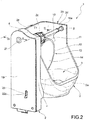
- the assembly formed by the shaft 10, the associated wing 11 and the obturator 12 may oscillate around the horizontal axis of said shaft 10 between a closed position (shown in figures 1 and 3 ) and an opened position (shown in figure 2 ).
- the obturator 12 When the obturator 12 finds itself in the closed position ( figures 1 and 3 ), it is adapted to substantially shuts the passage 3, preventing the ice cubes from coming from a forming device located higher up in the outlet passage 3 and, from this passage, to an underlying collection receptacle.
- the section of the obturator 12 is smaller than the corresponding section of the passage 3; however, the opening between them is such as to prevent an ice cube with predetermined dimensions from passing through the gap defined between them.
- the movement of the obturator 12 between the closed position and the opened position is controlled by means of a device housed in the spaces 5 and 6 defined within the region between the wall 4 and the wall 2e.
- control and command device 20 comprises a wire W made of a shape-memory material that is adapted to shrink when it is traversed by an electric current and re-expand when such electric current is lost.
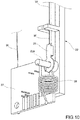
- the wire W has a terminal 21 anchored to a protrusion in the form of a pin 22a of a member 22 in the form of a connecting rod (see in particular figures 3 and 10 ).
- said protrusion 22a of the connecting rod member 22 extends through a vertical guide slot 23 provided in the cover 19.
- the connecting rod member 22 extends in an essentially vertical direction, through an interruption of the septum 7 and up to the end 10b of the shaft 10 (see figure 3 ).
- the shape-memory wire W extends essentially in a vertical direction until it reaches the periphery of a guide pulley indicated at 24 in figures 3 , 7 and 8 , which is mounted rotatable around a tubular protrusion 2f integral with the wall 2e of the bearing structure 2 ( figure 8 ).
- the shape-memory wire W extends vertically downward and the lower end thereof is provided with an electrical terminal 25 ( figures 7 and 11 ) connected electrically and mechanically to a terminal 26 fixed to a circuit board 27 mounted in the lower space 6 defined between the wall 4 and the wall 2e ( figures 2 , 7 and 11 ).
- the protrusion 22a of the connecting rod member 22 is connected to the upper end of a coil tension spring 28, the other end of which is anchored in a notch of the circuit board 27 (see in particular figure 10 ).
- the spring 28 tends to oppose the shrinking of the shape-memory wire W due to the passage of a current therethrough.
- the shaft 10 has a transverse formation 29 with a protrusion 30, eccentric to the axis of the shaft 10.
- the eccentric protrusion 30 extends through and beyond an arched slot opening 31 made in the wall 2e in the bearing structure 2 (see also figure 4 ).
- the arched opening 31 extends substantially according to an arc with a concentric circumference with the axis of the shaft 10.
- the eccentric protrusion 30 engages into an end opening 22b of the connecting rod member 22.
- the connecting rod member 22 and the formation 29 with the associated eccentric protrusion 30 form a slider-crank mechanism, mechanically coupled to the shaft 10.
- the lower end of the connecting rod member 22 is essentially shaped like an L and has a transverse arm 22c facing the actuating member 32a of a micro-switch 32 carried by the circuit board 27 ( figure 11 ).
- the transverse arm or branch 22c of the lower end of the connecting rod member 22 forms a terminal finger 22d ( figures 5 and 11 ) intended to cooperate with a photoelectric detector device 33 ( figure 11 ) comprising, for example, an LED diode and an associated phototransistor.
- the object of the photoelectric detector 33 is described in the following.
- valve device described above operates substantially as follows.
- the shaft 10 finds itself in an angular position so that the obturator 12 assumes the closed position shown in figures 1 , 3 and 7 .
- a control unit of the refrigerator appliance connected to the circuit board 27 of the valve device 1, couples the shape-memory wire W to a voltage source that causes the passage of an electric current through such wire.
- the passage 3 is then cleared whereby the ice cubes produced by an overlying device (not shown) may be delivered through the passage 3 to an underlying collecting receptacle.
- the control unit of the refrigerator appliance determines the interruption of the current in the shape-memory wire W, which cools down and consequently re-expands.
- the tension spring 28 Under the action of the tension spring 28, the lower end of the connecting rod member 22 is then drawn downward, guided by the vertical slot 23 ( figures 1 and 2 ) and, consequently, the protrusion 30 of the transverse formation 29 of the shaft 10 is drawn downward in the arched slot 31. This results in a rotation of the shaft 10 and of the associated obturator 12, counterclockwise for an observer of figure 2 , until the obturator 12 resumes the position of rest.
- the micro-switch 32 is actuated by the arm 22c of the connecting rod member 22 when the obturator 12 reaches the opened position of figure 2 and provides a corresponding signal to the control unit of the refrigerator appliance.
- the photoelectric detector 33 instead provides a signal to such control unit when, subsequently, the obturator 12 returns to the rest position following the interruption of the current in the shape-memory wire W.
- control and command device 20 associated with the obturator 12 has an absolutely silent operation.
- the obturator is automatically brought back to the closed position.
- the photoelectric detector 33 signals such condition to the control unit of the refrigerator appliance and said unit may then activate the heating resistor 17, arranged in the obturator 12, so as to melt said ice cube.
- the resistor 17 may furthermore be activated when the obturator 12 is locked in the closed position due to the formation of ice between the same and the dispensing conduit.
Landscapes
- Engineering & Computer Science (AREA)
- General Engineering & Computer Science (AREA)
- Mechanical Engineering (AREA)
- Chemical & Material Sciences (AREA)
- Combustion & Propulsion (AREA)
- Physics & Mathematics (AREA)
- Thermal Sciences (AREA)
- Production, Working, Storing, Or Distribution Of Ice (AREA)
- Cold Air Circulating Systems And Constructional Details In Refrigerators (AREA)
- Electrically Driven Valve-Operating Means (AREA)
Priority Applications (1)
| Application Number | Priority Date | Filing Date | Title |
|---|---|---|---|
| PL17182476T PL3276285T3 (pl) | 2016-07-25 | 2017-07-21 | Urządzenie zaworowe do przewodu w lodówce wydającego kostki lodu |
Applications Claiming Priority (1)
| Application Number | Priority Date | Filing Date | Title |
|---|---|---|---|
| IT102016000077707A IT201600077707A1 (it) | 2016-07-25 | 2016-07-25 | Dispositivo valvolare per un condotto di erogazione di cubetti di ghiaccio in un frigorifero. |
Publications (2)
| Publication Number | Publication Date |
|---|---|
| EP3276285A1 true EP3276285A1 (fr) | 2018-01-31 |
| EP3276285B1 EP3276285B1 (fr) | 2019-09-18 |
Family
ID=58159181
Family Applications (1)
| Application Number | Title | Priority Date | Filing Date |
|---|---|---|---|
| EP17182476.6A Active EP3276285B1 (fr) | 2016-07-25 | 2017-07-21 | Dispositif de soupape pour un conduit de distribution à cubes de glace dans un réfrigérateur |
Country Status (5)
| Country | Link |
|---|---|
| US (1) | US10233685B2 (fr) |
| EP (1) | EP3276285B1 (fr) |
| CN (1) | CN107654712A (fr) |
| IT (1) | IT201600077707A1 (fr) |
| PL (1) | PL3276285T3 (fr) |
Cited By (2)
| Publication number | Priority date | Publication date | Assignee | Title |
|---|---|---|---|---|
| WO2020200617A1 (fr) * | 2019-04-03 | 2020-10-08 | Rapitag Gmbh | Élément actionneur et procédé permettant de faire fonctionner un élément actionneur |
| WO2023045930A1 (fr) * | 2021-09-23 | 2023-03-30 | 青岛海尔电冰箱有限公司 | Procédé de commande d'appareil d'évacuation de glace, appareil d'évacuation de glace et ensemble corps de porte |
Families Citing this family (3)
| Publication number | Priority date | Publication date | Assignee | Title |
|---|---|---|---|---|
| CN112444028A (zh) * | 2019-08-29 | 2021-03-05 | 青岛海尔电冰箱有限公司 | 制冰系统分配器的控制方法与制冰系统分配器 |
| CN112444029A (zh) * | 2019-08-29 | 2021-03-05 | 青岛海尔电冰箱有限公司 | 制冰系统的分配器与具有该分配器的冰箱 |
| CN112444027A (zh) * | 2019-08-29 | 2021-03-05 | 青岛海尔电冰箱有限公司 | 制冰系统的分配器与具有该分配器的冰箱 |
Citations (8)
| Publication number | Priority date | Publication date | Assignee | Title |
|---|---|---|---|---|
| NL8006779A (nl) * | 1979-12-19 | 1981-07-16 | Diermayer Werner | Inrichting voor het regelen van de afvoer van een verbrandingsinrichting. |
| US4569206A (en) * | 1983-05-16 | 1986-02-11 | Kabushiki Kaisha Toshiba | Indirect cooling refrigerator with freezing and storage chambers and a forced air circulating path |
| US5176544A (en) * | 1989-06-21 | 1993-01-05 | Johnson Service Company | Shape memory actuator smart connector |
| US20080120911A1 (en) * | 2006-10-30 | 2008-05-29 | Gm Global Technology Operations, Inc. | Door Actuation Systems Using Active Materials |
| WO2010066726A2 (fr) * | 2008-12-08 | 2010-06-17 | BSH Bosch und Siemens Hausgeräte GmbH | Réfrigérateur |
| US20110314742A1 (en) * | 2010-06-25 | 2011-12-29 | Hon Hai Precision Industry Co., Ltd. | Mechanical shutter with shape memory element |
| US20130091772A1 (en) * | 2011-10-14 | 2013-04-18 | Justin Berger | Ice dispensing apparatus with a shape memory alloy actuator |
| DE102014206134A1 (de) * | 2014-04-01 | 2015-10-01 | Actuator Solutions GmbH | Gerät, insbesondere Haushaltsgerät, und Verfahren zum Betreiben eines Gerätes |
Family Cites Families (5)
| Publication number | Priority date | Publication date | Assignee | Title |
|---|---|---|---|---|
| EP1347132B1 (fr) * | 2002-03-19 | 2007-01-03 | Ford Global Technologies, LLC | Système de porte comportant indicateur de vérouillage pour véhicule |
| US6675536B1 (en) * | 2002-07-31 | 2004-01-13 | Williams-Pyro, Inc. | Door frame closing and securing apparatus |
| US8341958B2 (en) * | 2006-07-25 | 2013-01-01 | Brown James Holbrook | Shape memory alloy actuated device |
| US7971393B2 (en) * | 2006-10-30 | 2011-07-05 | GM Global Technology Operations LLC | Door actuation systems |
| EP2771969A4 (fr) * | 2011-10-26 | 2015-09-16 | Autosplice Inc | Appareil actionné par alliage à mémoire de forme et procédé pour fabriquer et construire cet appareil |
-
2016
- 2016-07-25 IT IT102016000077707A patent/IT201600077707A1/it unknown
-
2017
- 2017-07-21 EP EP17182476.6A patent/EP3276285B1/fr active Active
- 2017-07-21 PL PL17182476T patent/PL3276285T3/pl unknown
- 2017-07-24 CN CN201710605734.6A patent/CN107654712A/zh active Pending
- 2017-07-24 US US15/657,706 patent/US10233685B2/en not_active Expired - Fee Related
Patent Citations (8)
| Publication number | Priority date | Publication date | Assignee | Title |
|---|---|---|---|---|
| NL8006779A (nl) * | 1979-12-19 | 1981-07-16 | Diermayer Werner | Inrichting voor het regelen van de afvoer van een verbrandingsinrichting. |
| US4569206A (en) * | 1983-05-16 | 1986-02-11 | Kabushiki Kaisha Toshiba | Indirect cooling refrigerator with freezing and storage chambers and a forced air circulating path |
| US5176544A (en) * | 1989-06-21 | 1993-01-05 | Johnson Service Company | Shape memory actuator smart connector |
| US20080120911A1 (en) * | 2006-10-30 | 2008-05-29 | Gm Global Technology Operations, Inc. | Door Actuation Systems Using Active Materials |
| WO2010066726A2 (fr) * | 2008-12-08 | 2010-06-17 | BSH Bosch und Siemens Hausgeräte GmbH | Réfrigérateur |
| US20110314742A1 (en) * | 2010-06-25 | 2011-12-29 | Hon Hai Precision Industry Co., Ltd. | Mechanical shutter with shape memory element |
| US20130091772A1 (en) * | 2011-10-14 | 2013-04-18 | Justin Berger | Ice dispensing apparatus with a shape memory alloy actuator |
| DE102014206134A1 (de) * | 2014-04-01 | 2015-10-01 | Actuator Solutions GmbH | Gerät, insbesondere Haushaltsgerät, und Verfahren zum Betreiben eines Gerätes |
Cited By (3)
| Publication number | Priority date | Publication date | Assignee | Title |
|---|---|---|---|---|
| WO2020200617A1 (fr) * | 2019-04-03 | 2020-10-08 | Rapitag Gmbh | Élément actionneur et procédé permettant de faire fonctionner un élément actionneur |
| US11905935B2 (en) | 2019-04-03 | 2024-02-20 | Rapitag Gmbh | Actuator element and method for operating an actuator element |
| WO2023045930A1 (fr) * | 2021-09-23 | 2023-03-30 | 青岛海尔电冰箱有限公司 | Procédé de commande d'appareil d'évacuation de glace, appareil d'évacuation de glace et ensemble corps de porte |
Also Published As
| Publication number | Publication date |
|---|---|
| PL3276285T3 (pl) | 2020-05-18 |
| US10233685B2 (en) | 2019-03-19 |
| IT201600077707A1 (it) | 2018-01-25 |
| US20180023875A1 (en) | 2018-01-25 |
| EP3276285B1 (fr) | 2019-09-18 |
| CN107654712A (zh) | 2018-02-02 |
Similar Documents
| Publication | Publication Date | Title |
|---|---|---|
| US10233685B2 (en) | Valve device for an ice cube dispensing conduit in a refrigerator | |
| US9462928B2 (en) | Electrically-controlled actuator device, and washing agents dispensing device comprising such an actuator device | |
| CN101461021A (zh) | 保护开关 | |
| KR20130020394A (ko) | 세탁기의 배수밸브 구동장치 | |
| KR101487498B1 (ko) | 나선 스프링 구동기를 가진 모터 구동 선형 액추에이터를 사용한 가전제품 락 | |
| US3500005A (en) | Variable circuit timer | |
| EP3129539B1 (fr) | Commutateur caché de porte de sèche-linge | |
| US4473789A (en) | Motor starting switch with dual load disconnect | |
| US4196697A (en) | Feeding apparatus | |
| US3621165A (en) | Closure-operated safety switch for automatic appliance | |
| WO2009066039A3 (fr) | Appareil electromenager de preparation culinaire prevu pour etre tenu a la main muni d'un element guide cordon | |
| US1721222A (en) | Switch-operating mechanism | |
| CN215251799U (zh) | 一种开关盒 | |
| CN209133382U (zh) | 一种漏电保护插头复位按钮结构 | |
| RU2177372C2 (ru) | Электрический душ | |
| US9443670B2 (en) | Contamination resistant push button switch | |
| CN109036936A (zh) | 一种直动型接地开关 | |
| CN215191089U (zh) | 一种带安全开关的破壁机 | |
| CN1750202B (zh) | 发动机操作单元 | |
| US1877923A (en) | Electric switch | |
| CN209750790U (zh) | 一种门控开关安装结构以及烹饪电器 | |
| CN208256517U (zh) | 一种双电源开关的微动开关固定结构 | |
| CN202286107U (zh) | 一种预约加水豆浆机 | |
| US735531A (en) | Switch for systems of remote control. | |
| KR101730013B1 (ko) | 지렛대 방식의 제빙기용 급수 조절 장치 및 방법 |
Legal Events
| Date | Code | Title | Description |
|---|---|---|---|
| PUAI | Public reference made under article 153(3) epc to a published international application that has entered the european phase |
Free format text: ORIGINAL CODE: 0009012 |
|
| STAA | Information on the status of an ep patent application or granted ep patent |
Free format text: STATUS: THE APPLICATION HAS BEEN PUBLISHED |
|
| AK | Designated contracting states |
Kind code of ref document: A1 Designated state(s): AL AT BE BG CH CY CZ DE DK EE ES FI FR GB GR HR HU IE IS IT LI LT LU LV MC MK MT NL NO PL PT RO RS SE SI SK SM TR |
|
| AX | Request for extension of the european patent |
Extension state: BA ME |
|
| STAA | Information on the status of an ep patent application or granted ep patent |
Free format text: STATUS: REQUEST FOR EXAMINATION WAS MADE |
|
| 17P | Request for examination filed |
Effective date: 20180730 |
|
| RBV | Designated contracting states (corrected) |
Designated state(s): AL AT BE BG CH CY CZ DE DK EE ES FI FR GB GR HR HU IE IS IT LI LT LU LV MC MK MT NL NO PL PT RO RS SE SI SK SM TR |
|
| GRAP | Despatch of communication of intention to grant a patent |
Free format text: ORIGINAL CODE: EPIDOSNIGR1 |
|
| STAA | Information on the status of an ep patent application or granted ep patent |
Free format text: STATUS: GRANT OF PATENT IS INTENDED |
|
| RIC1 | Information provided on ipc code assigned before grant |
Ipc: F25C 5/00 20180101AFI20190328BHEP |
|
| INTG | Intention to grant announced |
Effective date: 20190415 |
|
| GRAS | Grant fee paid |
Free format text: ORIGINAL CODE: EPIDOSNIGR3 |
|
| GRAA | (expected) grant |
Free format text: ORIGINAL CODE: 0009210 |
|
| STAA | Information on the status of an ep patent application or granted ep patent |
Free format text: STATUS: THE PATENT HAS BEEN GRANTED |
|
| AK | Designated contracting states |
Kind code of ref document: B1 Designated state(s): AL AT BE BG CH CY CZ DE DK EE ES FI FR GB GR HR HU IE IS IT LI LT LU LV MC MK MT NL NO PL PT RO RS SE SI SK SM TR |
|
| REG | Reference to a national code |
Ref country code: GB Ref legal event code: FG4D |
|
| REG | Reference to a national code |
Ref country code: CH Ref legal event code: EP |
|
| REG | Reference to a national code |
Ref country code: DE Ref legal event code: R096 Ref document number: 602017007123 Country of ref document: DE |
|
| REG | Reference to a national code |
Ref country code: AT Ref legal event code: REF Ref document number: 1181826 Country of ref document: AT Kind code of ref document: T Effective date: 20191015 |
|
| REG | Reference to a national code |
Ref country code: IE Ref legal event code: FG4D |
|
| RAP2 | Party data changed (patent owner data changed or rights of a patent transferred) |
Owner name: ELBI INTERNATIONAL S.P.A. |
|
| REG | Reference to a national code |
Ref country code: NL Ref legal event code: MP Effective date: 20190918 |
|
| PG25 | Lapsed in a contracting state [announced via postgrant information from national office to epo] |
Ref country code: SE Free format text: LAPSE BECAUSE OF FAILURE TO SUBMIT A TRANSLATION OF THE DESCRIPTION OR TO PAY THE FEE WITHIN THE PRESCRIBED TIME-LIMIT Effective date: 20190918 Ref country code: HR Free format text: LAPSE BECAUSE OF FAILURE TO SUBMIT A TRANSLATION OF THE DESCRIPTION OR TO PAY THE FEE WITHIN THE PRESCRIBED TIME-LIMIT Effective date: 20190918 Ref country code: NO Free format text: LAPSE BECAUSE OF FAILURE TO SUBMIT A TRANSLATION OF THE DESCRIPTION OR TO PAY THE FEE WITHIN THE PRESCRIBED TIME-LIMIT Effective date: 20191218 Ref country code: FI Free format text: LAPSE BECAUSE OF FAILURE TO SUBMIT A TRANSLATION OF THE DESCRIPTION OR TO PAY THE FEE WITHIN THE PRESCRIBED TIME-LIMIT Effective date: 20190918 Ref country code: LT Free format text: LAPSE BECAUSE OF FAILURE TO SUBMIT A TRANSLATION OF THE DESCRIPTION OR TO PAY THE FEE WITHIN THE PRESCRIBED TIME-LIMIT Effective date: 20190918 Ref country code: BG Free format text: LAPSE BECAUSE OF FAILURE TO SUBMIT A TRANSLATION OF THE DESCRIPTION OR TO PAY THE FEE WITHIN THE PRESCRIBED TIME-LIMIT Effective date: 20191218 |
|
| REG | Reference to a national code |
Ref country code: LT Ref legal event code: MG4D |
|
| PG25 | Lapsed in a contracting state [announced via postgrant information from national office to epo] |
Ref country code: GR Free format text: LAPSE BECAUSE OF FAILURE TO SUBMIT A TRANSLATION OF THE DESCRIPTION OR TO PAY THE FEE WITHIN THE PRESCRIBED TIME-LIMIT Effective date: 20191219 Ref country code: LV Free format text: LAPSE BECAUSE OF FAILURE TO SUBMIT A TRANSLATION OF THE DESCRIPTION OR TO PAY THE FEE WITHIN THE PRESCRIBED TIME-LIMIT Effective date: 20190918 Ref country code: AL Free format text: LAPSE BECAUSE OF FAILURE TO SUBMIT A TRANSLATION OF THE DESCRIPTION OR TO PAY THE FEE WITHIN THE PRESCRIBED TIME-LIMIT Effective date: 20190918 Ref country code: RS Free format text: LAPSE BECAUSE OF FAILURE TO SUBMIT A TRANSLATION OF THE DESCRIPTION OR TO PAY THE FEE WITHIN THE PRESCRIBED TIME-LIMIT Effective date: 20190918 |
|
| REG | Reference to a national code |
Ref country code: AT Ref legal event code: MK05 Ref document number: 1181826 Country of ref document: AT Kind code of ref document: T Effective date: 20190918 |
|
| PG25 | Lapsed in a contracting state [announced via postgrant information from national office to epo] |
Ref country code: ES Free format text: LAPSE BECAUSE OF FAILURE TO SUBMIT A TRANSLATION OF THE DESCRIPTION OR TO PAY THE FEE WITHIN THE PRESCRIBED TIME-LIMIT Effective date: 20190918 Ref country code: NL Free format text: LAPSE BECAUSE OF FAILURE TO SUBMIT A TRANSLATION OF THE DESCRIPTION OR TO PAY THE FEE WITHIN THE PRESCRIBED TIME-LIMIT Effective date: 20190918 Ref country code: RO Free format text: LAPSE BECAUSE OF FAILURE TO SUBMIT A TRANSLATION OF THE DESCRIPTION OR TO PAY THE FEE WITHIN THE PRESCRIBED TIME-LIMIT Effective date: 20190918 Ref country code: PT Free format text: LAPSE BECAUSE OF FAILURE TO SUBMIT A TRANSLATION OF THE DESCRIPTION OR TO PAY THE FEE WITHIN THE PRESCRIBED TIME-LIMIT Effective date: 20200120 Ref country code: AT Free format text: LAPSE BECAUSE OF FAILURE TO SUBMIT A TRANSLATION OF THE DESCRIPTION OR TO PAY THE FEE WITHIN THE PRESCRIBED TIME-LIMIT Effective date: 20190918 Ref country code: EE Free format text: LAPSE BECAUSE OF FAILURE TO SUBMIT A TRANSLATION OF THE DESCRIPTION OR TO PAY THE FEE WITHIN THE PRESCRIBED TIME-LIMIT Effective date: 20190918 |
|
| PG25 | Lapsed in a contracting state [announced via postgrant information from national office to epo] |
Ref country code: IS Free format text: LAPSE BECAUSE OF FAILURE TO SUBMIT A TRANSLATION OF THE DESCRIPTION OR TO PAY THE FEE WITHIN THE PRESCRIBED TIME-LIMIT Effective date: 20200224 Ref country code: SM Free format text: LAPSE BECAUSE OF FAILURE TO SUBMIT A TRANSLATION OF THE DESCRIPTION OR TO PAY THE FEE WITHIN THE PRESCRIBED TIME-LIMIT Effective date: 20190918 Ref country code: SK Free format text: LAPSE BECAUSE OF FAILURE TO SUBMIT A TRANSLATION OF THE DESCRIPTION OR TO PAY THE FEE WITHIN THE PRESCRIBED TIME-LIMIT Effective date: 20190918 Ref country code: CZ Free format text: LAPSE BECAUSE OF FAILURE TO SUBMIT A TRANSLATION OF THE DESCRIPTION OR TO PAY THE FEE WITHIN THE PRESCRIBED TIME-LIMIT Effective date: 20190918 |
|
| REG | Reference to a national code |
Ref country code: DE Ref legal event code: R097 Ref document number: 602017007123 Country of ref document: DE |
|
| PLBE | No opposition filed within time limit |
Free format text: ORIGINAL CODE: 0009261 |
|
| STAA | Information on the status of an ep patent application or granted ep patent |
Free format text: STATUS: NO OPPOSITION FILED WITHIN TIME LIMIT |
|
| PG2D | Information on lapse in contracting state deleted |
Ref country code: IS |
|
| PG25 | Lapsed in a contracting state [announced via postgrant information from national office to epo] |
Ref country code: DK Free format text: LAPSE BECAUSE OF FAILURE TO SUBMIT A TRANSLATION OF THE DESCRIPTION OR TO PAY THE FEE WITHIN THE PRESCRIBED TIME-LIMIT Effective date: 20190918 Ref country code: IS Free format text: LAPSE BECAUSE OF FAILURE TO SUBMIT A TRANSLATION OF THE DESCRIPTION OR TO PAY THE FEE WITHIN THE PRESCRIBED TIME-LIMIT Effective date: 20200119 |
|
| PGFP | Annual fee paid to national office [announced via postgrant information from national office to epo] |
Ref country code: TR Payment date: 20200627 Year of fee payment: 4 |
|
| 26N | No opposition filed |
Effective date: 20200619 |
|
| PG25 | Lapsed in a contracting state [announced via postgrant information from national office to epo] |
Ref country code: SI Free format text: LAPSE BECAUSE OF FAILURE TO SUBMIT A TRANSLATION OF THE DESCRIPTION OR TO PAY THE FEE WITHIN THE PRESCRIBED TIME-LIMIT Effective date: 20190918 |
|
| PG25 | Lapsed in a contracting state [announced via postgrant information from national office to epo] |
Ref country code: MC Free format text: LAPSE BECAUSE OF FAILURE TO SUBMIT A TRANSLATION OF THE DESCRIPTION OR TO PAY THE FEE WITHIN THE PRESCRIBED TIME-LIMIT Effective date: 20190918 |
|
| REG | Reference to a national code |
Ref country code: CH Ref legal event code: PL |
|
| REG | Reference to a national code |
Ref country code: BE Ref legal event code: MM Effective date: 20200731 |
|
| PG25 | Lapsed in a contracting state [announced via postgrant information from national office to epo] |
Ref country code: LI Free format text: LAPSE BECAUSE OF NON-PAYMENT OF DUE FEES Effective date: 20200731 Ref country code: LU Free format text: LAPSE BECAUSE OF NON-PAYMENT OF DUE FEES Effective date: 20200721 Ref country code: CH Free format text: LAPSE BECAUSE OF NON-PAYMENT OF DUE FEES Effective date: 20200731 Ref country code: FR Free format text: LAPSE BECAUSE OF NON-PAYMENT OF DUE FEES Effective date: 20200731 |
|
| PG25 | Lapsed in a contracting state [announced via postgrant information from national office to epo] |
Ref country code: BE Free format text: LAPSE BECAUSE OF NON-PAYMENT OF DUE FEES Effective date: 20200731 |
|
| PG25 | Lapsed in a contracting state [announced via postgrant information from national office to epo] |
Ref country code: IE Free format text: LAPSE BECAUSE OF NON-PAYMENT OF DUE FEES Effective date: 20200721 |
|
| PGFP | Annual fee paid to national office [announced via postgrant information from national office to epo] |
Ref country code: IT Payment date: 20210706 Year of fee payment: 5 |
|
| PGFP | Annual fee paid to national office [announced via postgrant information from national office to epo] |
Ref country code: DE Payment date: 20210721 Year of fee payment: 5 |
|
| GBPC | Gb: european patent ceased through non-payment of renewal fee |
Effective date: 20210721 |
|
| PG25 | Lapsed in a contracting state [announced via postgrant information from national office to epo] |
Ref country code: GB Free format text: LAPSE BECAUSE OF NON-PAYMENT OF DUE FEES Effective date: 20210721 |
|
| PG25 | Lapsed in a contracting state [announced via postgrant information from national office to epo] |
Ref country code: MT Free format text: LAPSE BECAUSE OF FAILURE TO SUBMIT A TRANSLATION OF THE DESCRIPTION OR TO PAY THE FEE WITHIN THE PRESCRIBED TIME-LIMIT Effective date: 20190918 Ref country code: CY Free format text: LAPSE BECAUSE OF FAILURE TO SUBMIT A TRANSLATION OF THE DESCRIPTION OR TO PAY THE FEE WITHIN THE PRESCRIBED TIME-LIMIT Effective date: 20190918 |
|
| PG25 | Lapsed in a contracting state [announced via postgrant information from national office to epo] |
Ref country code: MK Free format text: LAPSE BECAUSE OF FAILURE TO SUBMIT A TRANSLATION OF THE DESCRIPTION OR TO PAY THE FEE WITHIN THE PRESCRIBED TIME-LIMIT Effective date: 20190918 |
|
| PG25 | Lapsed in a contracting state [announced via postgrant information from national office to epo] |
Ref country code: PL Free format text: LAPSE BECAUSE OF NON-PAYMENT OF DUE FEES Effective date: 20200721 |
|
| REG | Reference to a national code |
Ref country code: DE Ref legal event code: R119 Ref document number: 602017007123 Country of ref document: DE |
|
| PG25 | Lapsed in a contracting state [announced via postgrant information from national office to epo] |
Ref country code: DE Free format text: LAPSE BECAUSE OF NON-PAYMENT OF DUE FEES Effective date: 20230201 |
|
| PG25 | Lapsed in a contracting state [announced via postgrant information from national office to epo] |
Ref country code: IT Free format text: LAPSE BECAUSE OF NON-PAYMENT OF DUE FEES Effective date: 20220721 |
|
| PG25 | Lapsed in a contracting state [announced via postgrant information from national office to epo] |
Ref country code: TR Free format text: LAPSE BECAUSE OF NON-PAYMENT OF DUE FEES Effective date: 20210721 |