EP3276338A2 - Röntgenfluoreszenzanalysator - Google Patents
Röntgenfluoreszenzanalysator Download PDFInfo
- Publication number
- EP3276338A2 EP3276338A2 EP17183698.4A EP17183698A EP3276338A2 EP 3276338 A2 EP3276338 A2 EP 3276338A2 EP 17183698 A EP17183698 A EP 17183698A EP 3276338 A2 EP3276338 A2 EP 3276338A2
- Authority
- EP
- European Patent Office
- Prior art keywords
- xrf
- analyzer
- sample
- processor
- filter
- Prior art date
- Legal status (The legal status is an assumption and is not a legal conclusion. Google has not performed a legal analysis and makes no representation as to the accuracy of the status listed.)
- Granted
Links
Images





Classifications
-
- G—PHYSICS
- G01—MEASURING; TESTING
- G01N—INVESTIGATING OR ANALYSING MATERIALS BY DETERMINING THEIR CHEMICAL OR PHYSICAL PROPERTIES
- G01N23/00—Investigating or analysing materials by the use of wave or particle radiation, e.g. X-rays or neutrons, not covered by groups G01N3/00 – G01N17/00, G01N21/00 or G01N22/00
- G01N23/22—Investigating or analysing materials by the use of wave or particle radiation, e.g. X-rays or neutrons, not covered by groups G01N3/00 – G01N17/00, G01N21/00 or G01N22/00 by measuring secondary emission from the material
- G01N23/223—Investigating or analysing materials by the use of wave or particle radiation, e.g. X-rays or neutrons, not covered by groups G01N3/00 – G01N17/00, G01N21/00 or G01N22/00 by measuring secondary emission from the material by irradiating the sample with X-rays or gamma-rays and by measuring X-ray fluorescence
-
- G—PHYSICS
- G01—MEASURING; TESTING
- G01N—INVESTIGATING OR ANALYSING MATERIALS BY DETERMINING THEIR CHEMICAL OR PHYSICAL PROPERTIES
- G01N2223/00—Investigating materials by wave or particle radiation
- G01N2223/30—Accessories, mechanical or electrical features
- G01N2223/301—Accessories, mechanical or electrical features portable apparatus
-
- G—PHYSICS
- G01—MEASURING; TESTING
- G01N—INVESTIGATING OR ANALYSING MATERIALS BY DETERMINING THEIR CHEMICAL OR PHYSICAL PROPERTIES
- G01N2223/00—Investigating materials by wave or particle radiation
- G01N2223/30—Accessories, mechanical or electrical features
- G01N2223/313—Accessories, mechanical or electrical features filters, rotating filter disc
-
- G—PHYSICS
- G01—MEASURING; TESTING
- G01N—INVESTIGATING OR ANALYSING MATERIALS BY DETERMINING THEIR CHEMICAL OR PHYSICAL PROPERTIES
- G01N2223/00—Investigating materials by wave or particle radiation
- G01N2223/40—Imaging
- G01N2223/408—Imaging display on monitor
-
- G—PHYSICS
- G02—OPTICS
- G02B—OPTICAL ELEMENTS, SYSTEMS OR APPARATUS
- G02B27/00—Optical systems or apparatus not provided for by any of the groups G02B1/00 - G02B26/00, G02B30/00
- G02B27/01—Head-up displays
- G02B27/017—Head mounted
-
- G—PHYSICS
- G06—COMPUTING OR CALCULATING; COUNTING
- G06F—ELECTRIC DIGITAL DATA PROCESSING
- G06F3/00—Input arrangements for transferring data to be processed into a form capable of being handled by the computer; Output arrangements for transferring data from processing unit to output unit, e.g. interface arrangements
- G06F3/01—Input arrangements or combined input and output arrangements for interaction between user and computer
- G06F3/048—Interaction techniques based on graphical user interfaces [GUI]
- G06F3/0484—Interaction techniques based on graphical user interfaces [GUI] for the control of specific functions or operations, e.g. selecting or manipulating an object, an image or a displayed text element, setting a parameter value or selecting a range
- G06F3/04842—Selection of displayed objects or displayed text elements
Definitions
- XRF analyzers are used to detect elements present in a sample.
- a typical XRF analyzer includes an X-ray source for directing X-rays to the sample and a detector responsive to the X-rays emitted from the sample.
- An analyzer processes the output signals produced by the detector and divides the energy levels of the detected X-ray photons into several energy subranges by counts of the number of X-ray photons detected to produce a graph depicting the X-ray spectrum of the sample.
- an operator can detect whether certain elements are present in sample for use in such applications as, inter alia, security and law enforcement, environmental applications, artistic and historic works, biomedical and pharmaceutical applications, process chemistry, and the like.
- Filtering of particular ranges of X-rays permits more specific ranges of materials to be identified, better quantification accuracies, and lower levels of detection.
- the amount of different filter choices in a typical XRF analyzer is limited because of the size of the analyzer and the construction of the analyzer. Such limited filter choices limits the different materials that the analyzer can accurately measure.
- Bragg reflection a known phenomenon characterized by constructive X-ray reflection peaks. Such reflections cannot reliably be filtered and cannot accurately be compensated for in an analysis algorithm. Bragg reflections may give indications of incorrect relative concentrations of elements within the sample being tested.
- each auxiliary analyzer or support device must be repositioned, as well, which is time-consuming and may affect accuracy of the measurement.
- At least some known XRF analyzers are stand-alone devices that have little or no communications abilities with offboard components or are connected after data collection, to off board analysis equipment using a communications cable.
- X-ray fluorescence (XRF) analyzer includes a radiation source assembly including a first centerline axis and configured to direct an X-ray beam to impinge on a sample to be tested.
- the XRF analyzer also includes a radiation detector assembly including a second centerline axis configured to sense X-ray fluorescence (XRF) emitted from the sample in response to the X-ray beam.
- the XRF analyzer further includes a processor configured to determine a property of the sample to be tested from the emitted XRF, and a proximity sensor configured to continuously measure a distance between the XRF analyzer and the sample to be tested, the distance being at least one of displayed to a user and used by the processor to determine the property.
- a method for processing X-ray fluorescence data in an X-ray Fluorescence (XRF) analyzer that includes a computer device coupled to a memory device includes receiving, by the computer device, X-ray fluorescence data from an X-ray detector device, generating X-ray fluorescence spectrum data using the received X-ray fluorescence data, receiving, by the computer device, distance data relative to a distance between the XRF analyzer and a sample, and determining an elemental composition of the sample using the generated X-ray fluorescence spectrum data and the distance data.
- XRF X-ray Fluorescence
- one or more non-transitory computer-readable storage media has computer-executable instructions embodied thereon, wherein when executed by at least one processor, the computer-executable instructions cause the processor to select a first filter of the plurality of individually selectable filters, indicate, to the at least one processor, the filter selected.
- the computer-executable instructions cause the processor to select one of the first filter-in position and the second no-filter position on the separate manual filter assembly and emit radiation through the selected filter and the separate manual filter assembly.
- the computer-executable instructions cause the processor to receive, by the at least one processor, X-ray fluorescence data from an X-ray detector device, generate X-ray fluorescence spectrum data using the received X-ray fluorescence data, receive, by the computer device, distance data relative to a distance between the XRF analyzer and a sample, and determine an elemental composition of the sample using the generated X-ray fluorescence spectrum data and the distance data.
- the computer-executable instructions cause the processor to transmit raw spectrum data to the visual display in real-time, receive a user selection from an input device associated with the visual display, and modify the raw spectrum data based on the received input.
- FIGS. 1-13 show example embodiments of the methods and systems described herein.
- Embodiments of the present disclosure describe a configurable X-ray Fluorescence (XRF) spectrometer that includes detection hardware, a plurality of accessories and attachments, and an accompanying software suite that permits real-time access to a raw spectrum of XRF data to the operator.
- the described XRF spectrometer includes customizable X-ray flux and detector parameters that permits precise calibrations targeting unique detection applications, enhanced minimum backscatter sample detection, and infrared sample detection.
- the XRF spectrometer may be embodied in a hand-held, counter-top, or bench-top enclosures.
- the XRF spectrometer includes a unique analytical geometry optimized for reduced Bragg or constructive X-ray reflection peaks.
- a rail mounting feature, (Picatinny (AKA MIL-STD-1913 (AR)) is configured to interface with and support a tripod boom and other articulating devices and auxiliary instruments configured to enhance the data collected by the XRF spectrometer or supplement the data collected by the XRF spectrometer with data of a different kind or character.
- the XRF spectrometer includes removable and customizable beam-hardening filters combined with a selectable multi-position filter wheel assembly and selectable collimation objective masks.
- An optional vacuum pump and helium purge permits boosting light-element (low atomic number sample) signals.
- a distance measuring proximity sensor is used for precise instrument to sample distance measurement during detection and feedback for analysis.
- detectors having active areas with diameters of 7, 20, 30, 50 mm 2 may be preselected and then assembled with the XRF spectrometer. In other embodiments, other diameter detectors may be included with the XRF spectrometer.
- a full color video camera is used for sample alignment and reporting of results.
- the XRF spectrometer may be used with an external computer or may operate as a stand-alone device and may also be used with a desktop stand, countertop stand, and exam table for analysis of small samples. A benchtop stand may be used for irregularly-shaped samples and higher power applications.
- the XRF spectrometer provides control over a wide range of accelerating voltages and anode currents.
- the XRF spectrometer is provided via Universal Service Bus (USB), Bluetooth ®, other wireless protocols, and via wired remote in addition to the on instrument display and touchscreen.
- the XRF spectrometer also includes support for Wi-Fi data transfer and setup.
- the XRF spectrometer includes wireless connectivity for connecting to wearable viewing systems, such as, but not limited to. Occulus®, Google Glass and other augmented reality (AR) devices, and tablets, laptops, cell phones and the like.
- the XRF spectrometer includes an onboard touchscreen graphical user interface (GUI) and a pistol grip for hand-held operation. High-visibility warnings and indicators alert the operator to conditions that may affect detection or accuracy, or user safety.
- the XRF spectrometer is configured to receive either onboard battery power, external DC power, and/or alternating current (AC) power.
- AC alternating current
- the X-ray fluorescence (XRF) analyzer or spectrometer introduced above and described in detail below includes a radiation source assembly having a first centerline axis and is configured to direct a beam of radiation, typically an X-ray beam in the direction of the first centerline axis to impinge on a sample to be tested.
- the XRF analyzer also includes a radiation detector assembly having a second centerline axis. The radiation detector assembly is configured to sense X-ray fluorescence (XRF) emitted from the sample in response to the X-ray beam.
- XRF X-ray fluorescence
- a processor is configured to determine a property of the sample to be tested from the emitted XRF and a proximity sensor is configured to continuously measure a distance between the a surface of the XRF analyzer, which is typically a part of a front face of the XRF analyzer, and the sample to be tested. The distance is displayed to a user and/or used by the processor to facilitate determining the property.
- the XRF analyzer may also include a plurality of proximity sensors and may be configured to determine a positional orientation of the XRF analyzer with respect to the sample to be tested using the plurality of proximity sensors.
- the first centerline axis and the second centerline axis may be offset laterally with respect to each other by a first angle.
- the first angle may be selected to facilitate reducing Bragg reflections. In some embodiments, the first angle is less than 30°. In one embodiment, the first angle is approximately 10°.
- a projection of the first centerline axis on a plane and a projection of the second centerline axis on the plane may intersect to form a second angle, which may be selectively variable to modify a position of an intersection of the projection of the first centerline axis and the projection of the second centerline axis on the plane.
- the second angle may also be selected to facilitate reducing Bragg reflections and may be selected to be less than 90°. In one embodiment, the second angle equals approximately 70°.
- the XRF analyzer may include a Near Field Communications (NFC) reader/writer configured to sense a presence or absence of predetermined accessories.
- the NFC reader/writer may be configured to sense at least one of a position and an orientation of the XRF analyzer and prevent operation of the radiation source assembly when the position and an orientation of the XRF analyzer are outside a predetermined range or a determined range.
- the NFC reader/writer may be configured to sense when the XRF analyzer may be installed in an accessory and to at least one of permit and prevent activation of predetermined operational features or modes based on the installation.
- a method of processing X-ray fluorescence data in a hand-held X-ray Fluorescence (XRF) analyzer is also described in detail below.
- the method is implemented using a computer device coupled to a memory device.
- the method includes steps, such as, receiving, by the computer device, X-ray fluorescence data from an X-ray detector device, generating X-ray fluorescence spectrum data using the received X-ray fluorescence data, receiving, by the computer device, distance data relative to a distance between the XRF analyzer and a sample, and determining an elemental composition of the sample using the generated X-ray fluorescence spectrum data and the received distance data.
- the method may further include emitting a beam of X-rays from a radiation source assembly positioned onboard the XRF analyzer.
- the XRF analyzer may include a selectable filter assembly including a plurality of individually selectable filters in series with a separate manual filter assembly selectable between a first filter-in position and a second no-filter position.
- the method may also include selecting a first filter of the plurality of individually selectable filters, indicating, to the computer device, the filter selected, selecting one of the first filter-in position and the second no-filter position on the separate manual filter assembly, and emitting radiation through the selected filter and the separate manual filter assembly.
- the XRF analyzer may include a visual display and the method may further include transmitting raw spectrum data to the visual display in real-time, receiving a user selection from an input device associated with the visual display, and modifying the raw spectrum data based on the received user selection.
- the XRF analyzer may include an instrument mounting rail coupled to the XRF analyzer and the method may further include receiving a signal from an instrument mounted on the instrument mounting rail.
- the method may further include receiving X-ray photons emitted from a sample through a faceplate window by an X-ray detector device and receiving a live video image through the faceplate window from an integrated video camera.
- the method may also include transceiving wirelessly, augmented reality data between the XRF analyzer and an augmented reality device wearable by a user and communicatively coupled to the XRF analyzer.
- augmented reality is a live direct or indirect view of a physical, real-world environment whose elements are augmented by computer-generated sensory input such as sound, video, graphics or GPS data.
- Hardware components used for AR may include a processor, a display screen, sensors, input devices, a camera, and MEMS sensors, such as, an accelerometer, GPS, and a solid state compass.
- non-transitory computer-readable storage media having computer-executable instructions embodied thereon.
- the computer-executable instructions When executed by a processor of the XRF analyzer, the computer-executable instructions cause the processor to select a first filter of a plurality of individually selectable filters and to indicate to the at least one processor, the filter selected.
- the instructions may also cause the processor to select one of a first filter-in position and a second no-filter position on a separate manual filter assembly, emit radiation from a radiation source assembly through the selected filter and the separate manual filter assembly, receive, by the at least one processor, X-ray fluorescence data from an X-ray detector device of the XRF analyzer, and generate X-ray fluorescence spectrum data using the received X-ray fluorescence data.
- the instructions may also cause the processor to receive, by the at least one processor, distance data relative to a distance between the XRF analyzer and a sample and to determine an elemental composition of the sample using the generated X-ray fluorescence spectrum data and the distance data.
- the instructions may further cause the processor to transmit raw spectrum data to a visual display in real-time, receive a user selection from an input device associated with the visual display, and modify the raw spectrum data based on the received user selection.
- the computer-executable instructions may further cause the processor to receive a signal from an instrument mounted on an instrument mounting rail coupled to the XRF analyzer, receive a live video image through a window of the XRF analyzer from an integrated video camera, and transceive wirelessly, augmented reality data between the XRF analyzer and an augmented reality device wearable by a user and communicatively coupled to the XRF analyzer.
- a computer program is provided, and the program is embodied on a computer readable medium.
- the system is executed on a single computer system, without requiring a connection to a sever computer.
- the operating system can be one of the Microsoft Windows TM family of operating systems (e.g., Windows 2000, Windows XP, Windows XP x64 Edition, Windows Vista, Widows 7, Windows 8, Windows CE, Windows Mobile), Linux®, HP-UX®, UNIX®, Sun OS, Solaris, Mac OS X, Alpha OS, AIX, IRIX32, IRIX64, iOSTM, AndroidTM etc. Other operating systems may be used.
- Microsoft Windows is a trademark of Microsoft Corporation.
- Android is a trademark of Google Inc.
- the system includes multiple components distributed among a plurality of computing devices.
- One or more components may be in the form of computer-executable instructions embodied in a computer-readable medium.
- the systems and processes are not limited to the specific embodiments described herein.
- components of each system and each process can be practiced independent and separate from other components and processes described herein.
- Each component and process can also be used in combination with other assembly packages and processes.
- database may refer to either a body of data, a relational database management system (RDBMS), or to both.
- RDBMS relational database management system
- a database may include any collection of data including hierarchical databases, relational databases, flat file databases, object-relational databases, object oriented databases, and any other structured collection of records or data that is stored in a computer system.
- RDBMS's include, but are not limited to including, Oracle® Database, MySQL, IBM® DB2, Microsoft® SQL Server, Sybase®, and PostgreSQL.
- any database may be used that enables the systems and methods described herein.
- real-time refers to outcomes occurring at a substantially short time period after a change in the inputs affecting the outcome, for example, receiving fluorescence data, calculating a spectrum and making the calculated spectrum available for display, transmission or further processing.
- the period may be the amount of time between each iteration of a regularly repeated task or between one task and another.
- the time period is a result of design parameters of the real-time system that may be selected based on the importance of the outcome and/or the capability of the system implementing processing of the inputs to generate the outcome. Additionally, events occurring in real-time occur without substantial intentional delay.
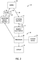
- Sample 32 becomes excited after being exposed to primary beam 18. This excitation causes sample 32 to emit a secondary (i.e., characteristic or fluorescent) radiation 21. Secondary radiation 21 is collected by radiation detector assembly 14.
- Radiation detector assembly 14 includes electronic circuitry, which is sometimes referred to as a preamplifier, that converts collected secondary radiation to a detector signal 24 (i.e., a voltage signal or an electronic signal) and provides the detector signal 24 to analyzer 16.
- analyzer 16 includes a digital pulse processor or multi-channel analyzer.
- radiation source assembly 12 is a radiation source that projects a primary beam of radiation toward a sample 32 that is selected to be analyzed.
- radiation source assembly 12 may include an X-ray tube that projects primary beam 18 of X-rays toward sample 32.
- radiation source assembly 12 is a radioactive isotope, which projects a primary beam of gamma rays toward sample 32.
- radiation source assembly 12 is an electron beam source that projects a primary beam of electrons towards the sample 32. Any suitable beam source, or plurality of sources, known in the art can be used as radiation source assembly 12.
- sample 32 includes irregular-shaped objects, relatively small objects, such as, but not limited to powders, particulates, and shavings, and objects that include protrusions and pointed extensions.
- filter wheel assembly 26 is positioned between radiation source assembly 12 and sample 32.
- filter wheel assembly 26 may include one or more selectable filters communicatively coupled to processor 20.
- Processor 20 may be configured to select one or more of a plurality of filters that may be applied by filter wheel assembly 26.
- Processor 20 may also be configured to select that no filter be applied to primary beam 18.
- filter wheel assembly 26 may include a first filter 34 that modifies characteristics of primary beam 18 in a first manner and a second filter 36 that modifies characteristics of primary beam 18 in a second manner. Examples of materials included within first filter 34 and/or second filter 36 include, but are not limited to, copper, aluminum, and titanium.
- filter wheel assembly 26 may include any number of filters that allows radiation assembly 10 to function as described herein.
- Sample 32 becomes excited after being exposed to primary beam 18. This excitation causes sample 32 to emit secondary (i.e. characteristic fluorescent) radiation 21. Secondary radiation 21 is impinged upon radiation detector assembly 14. Radiation detector assembly 14 converts the secondary radiation to a detector signal 24, for example, a voltage signal or an electronic signal that is representative of the secondary radiation. Radiation detector assembly 14 provides detector signal 24 to readout electronics 17, which determine an energy spectrum of collected secondary radiation 21. Readout electronics 17 provide this energy spectrum to processor 20.
- a detector signal 24 for example, a voltage signal or an electronic signal that is representative of the secondary radiation.
- Readout electronics 17 provide this energy spectrum to processor 20.
- readout electronics 17 and/or processor 20 may take action to receive detector signal 24 and/or the energy spectrum (e.g., may perform polling or a retrieve function in order to receive the signal and/or spectrum).
- Processor 20 determines the unique elemental composition of the sample.
- Processor 20 may also be referred to as an analyzer and may include a digital pulse processor.
- Display 19 allows an operator to view results provided to display 19 by processor 20, for example, an operator may view the energy spectrum or a derived elemental composition and a final analytical result, such as an alloy identification of sample 32.
- Display 19 may be built into a hand-held enclosure or it may be in the form of a small hand-held computer or personal digital assistant (PDA) that is communicatively coupled to processor 20 or it may be a general purpose computer of any size or configuration.
- PDA personal digital assistant
- radiation assembly 10 determines measurement conditions to be applied during an analysis of a sample, for example, sample 32.
- processor 20 controls operation of radiation assembly 10, and more specifically, controls operation of radiation source assembly 12.
- processor 20 operates radiation source assembly 12 in accordance with at least one predefined measurement condition to perform a first elemental analysis of sample 32.
- processor 20 may be configured to operate radiation source assembly 12 in accordance with a first measurement condition or a first set of measurement conditions.
- the measurement condition includes, but is not limited to, a length of time the measurement is taken, a level of voltage applied to radiation source assembly 12, a level of current applied to radiation source assembly 12, and/or a type of filter used.
- a first predefined level of voltage is applied to radiation source assembly 12 for a first predefined length of time to perform the first elemental analysis of sample 32.
- the first elemental analysis may also be referred to as an initial analysis of sample 32 that provides an initial determination of an alloy grade of sample 32.
- the first elemental analysis is not stringent enough to determine, to a predefined level of certainty, that sample 32 is composed of the initial determination of the alloy grade.
- the first set of measurement conditions may be stored in a storage or memory device, for example, memory device 22.
- an aluminum/titanium (Al/Ti) filter is positioned between sample 32 and radiation detector assembly 14, and power having 40 kV and 10 microamps is applied to radiation source assembly 12 for five seconds.
- a second elemental analysis may also be referred to as a phase two analysis.
- the empty filter wheel position is selected, the manual filter holder is empty and power having 15kV and 15 microamps is applied to radiation source assembly 12 for up to 60 seconds.
- Additional phases may be used to allow detection of low concentrations of lower energy elements such as sulfur without the presence of ubiquitous high energy elements such as iron flooding the spectrum or to allow examining specific regions of the spectra with higher accuracy.
- FIG. 3 is a perspective view of radiation assembly 10 embodied in a portable hand-held format.
- radiation assembly 10 is contained within a pistol-grip housing 302 that includes a nose section 304, a body 306, a control and display section 308, and a grip 310.
- Nose section 304 extends away from body 306 in a forward direction 312 that is generally towards the sample to be tested (not shown).
- a faceplate 314 covers the most forward extent of nose section 304. Faceplate 314 is removably coupled to nose section 304 using one or more fasteners 316, such as, but not limited to screws.
- faceplate 314 includes a first proximity opening 318 configured to permit sensing a proximity of faceplate 314 to, for example, the sample to be tested. First proximity opening 318 permits emission of signals from a proximity sensor (not shown in FIG. 3 ) positioned behind faceplate 314 towards the sample to be tested.
- Nose section 304 also includes a second opening 320 configured to permit passage of radiation from radiation source assembly 12 (shown in FIGS. 1 and 2 ), secondary radiation from the sample to be tested (not shown), and visible, near infrared, and infrared wavelength electromagnetic radiation for reception by an integrated video camera (not shown in FIG. 3 ) positioned within nose section 304.
- the integrated video camera provides visualization and accurate positioning of the measurement spot.
- Filter wheel assembly 26 (shown in FIG. 2 ) is also located behind faceplate 314.
- Body 306 contains analyzer 16 (shown in FIG. 1 ), power supplies (not shown in FIG. 3 ), and other auxiliary components described in detail below.
- Control and display section 308 is coupled to or forms a part of body 306.
- Grip 310 provides a hand hold support for radiation assembly 10 and may include a trigger control 324 and an internal battery (not shown in FIG. 3 ).
- An instrument mounting rail 326 for example, a rail known as a Picatinny (AKA MIL-STD-1913 (AR)) rail or a weaver rail is positioned along a top surface 328 of body 306.
- FIG. 4 is a view of a display screen 402 used with control and display section 308 (shown in FIG. 3 ).
- control and display section 308 includes at least one media output component 404 for presenting information to a user.
- Media output component 404 is embodied in any component capable of conveying information to the user.
- media output component 404 includes an output adapter such as a video adapter 406 and/or an audio adapter 408.
- the output adapter is operatively coupled to processor 20 (shown in FIG.
- an output device such as a display device, a liquid crystal display (LCD), organic light emitting diode (OLED) display, or “electronic ink” display, or an audio output device, a speaker or headphones.
- a display device such as a liquid crystal display (LCD), organic light emitting diode (OLED) display, or “electronic ink” display, or an audio output device, a speaker or headphones.
- LCD liquid crystal display
- OLED organic light emitting diode
- control and display section 308 includes an input device 410 for receiving a user selection from the user.
- Input device 410 may include, for example, a keyboard, a pointing device, a mouse, a stylus, a touch sensitive panel, a touch pad, a touch screen, a gyroscope, an accelerometer, a position detector, or an audio input device.
- a single component such as a touch screen may function as both an output device of media output component 404 and input device 410.
- Additional "hard" controls 412 such as, but not limited to, buttons, knobs and the like, may be positioned on control and display section 308 or may be located on another section of radiation assembly 10, for example, trigger control 324.
- Control and display section 308 may also include a communication interface 414, which is communicatively coupleable to a remote device such as a server system 416.
- Communication interface 414 may include, for example, a wired or wireless network adapter or a wireless data transceiver for use with a mobile phone network, Global System for Mobile communications (GSM), 3G, or other mobile data network or Worldwide Interoperability for Microwave Access (WIMAX).
- Server system 416 may further include other servers or may be communicatively coupled to other servers, such as, but not limited to a database server 418, a web server 420, and the like.
- a memory storage device 422 is coupled to database server 418.
- Servers 416, 418, and 420 are coupled in a local area network (LAN) 424, which is accessible to the Internet 426 including cloud computing resources.
- LAN local area network
- Stored in memory storage device 422 are, for example, computer readable instructions for providing a user interface to the user via media output component 404 and, optionally, receiving and processing a user selection from input device 410.
- a client application executing on control and display section 308 permits the user to interact with a server application executing on server system 416, on one of the other servers in server system 416, for example, servers 418 and 420, or Internet 426.
- FIG. 5 is a forward elevation view of nose section 304 illustrating access door 322 being open.
- Access door 322 permits access to a collimator/manual filter holder assembly 500.
- a manual filter holder 502 may hold one of the standard filters supplied by a manufacturer or may contain the user fabricated filter described above. The manual filter may be used in conjunction with the blank position in filter wheel assembly 26 (shown in FIGS. 1 and 3 ) or in conjunction with one of the standard filters in filter wheel assembly 26.
- a collimator assembly 504 includes a bore 506 having selectable diameter sleeves 508, which affect the spot size on the sample to be tested.
- the user can fabricate a replaceable customizable manual filter, for example, by using a hand-held punch to punch out a filter from a sheet of a material or a plurality of materials that is determined to have the filtering characteristics needed to produce the specific band of X-rays desired.
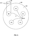
- FIG. 6 is a block diagram of a filter wheel 600 that may be used with filter wheel assembly 26 of radiation assembly 10 (shown in FIG. 1 ).
- filter wheel 600 includes a circular body 602 that includes a plurality of filter positons 604 that each contains a different filter. Each filter may be defined by a material and a thickness of the respective filter. Additionally, one or more of filter positions 604 may contain more than one filter layer.
- a first filter position 606 may include a single layer 608 having a first thickness 610.
- a second filter position 612 may include two separate filter layers positioned face-to face in second filter position 612. Each of the two separate filter layers may have respective layer thicknesses that can be the same thickness or different thicknesses with respect to each other.
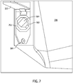
- FIG. 7 is a side elevation view of radiation assembly 10 in accordance with an example embodiment of the present disclosure.
- nose section 304 includes a collimator and filter compartment 702 that contains and permits access to collimator assembly 504 and manual filter holder 502.
- FIG. 8 is a cutaway view of an instrument front end 800 of radiation assembly 10.
- instrument front end 800 includes manual filter holder 502, collimator assembly 504, filter wheel 600, an integrated video camera 802, and an electronics board 804.
- Instrument front end 800 also includes a plurality of seals configured to maintain, for example, a vacuum or a purge on an atmosphere space 806, shown approximately by box 807 in FIG. 8 .
- Radiation source assembly 12 includes a centerline axis 808 that extends approximately orthogonally with respect to a radiation source device 810, filter wheel assembly 26, containing filter wheel 600, manual filter holder 502, and collimator assembly 504. Centerline axis 808 is offset from a vertical axis 812 by an angle 814 of approximately 45°.
- Vertical axis 812 refers to an axis that is substantially vertical with respect to the Earth when radiation assembly 10 is held in a hand of the user by grip 310 and being pointed approximately parallel to the ground.
- Radiation detector assembly 14 includes a centerline axis 816. Centerline axis 816 is offset from vertical axis 812 by an angle 822 of approximately 65°. Centerline axis 808 and centerline axis 816 are laterally offset by an angle (not shown in FIG. 8 ) of, for example, approximately 10°, meaning radiation detector assembly 14 is shifted laterally (i.e., into or out of the page in FIG. 8 ) with respect to radiation source assembly 12.
- the different angles (814, 822) of alignment of radiation source assembly 12 and radiation detector assembly 14 and well as the lateral offset of radiation source assembly 12 and radiation detector assembly 14 are unique features of radiation assembly 10 that facilitate mitigating the effects of Bragg reflection.
- a proximity sensor 824 is configured to be used as a distance measurement.
- the user sets a distance from the sample to be tested and receives feedback from control and display section 308 that provides an indication of the difference between the positions of radiation assembly 10 from the set position.
- a plurality of proximity sensors 824 are used to also indicate an angular offset of faceplate 314 with respect to a surface of the sample to be tested.
- An apex 826 ( FIG. 11 ) of radiation assembly 10 is defined at the intersection or near intersection of centerline axis 808 and centerline axis 816. Typically, apex 826 is located proximate faceplate 314.
- radiation source assembly 12 and/or radiation detector assembly 14 are rotatable about a pivot or axis of rotation 828, 830 respectively. Radiation source assembly 12 and radiation detector assembly 14 are rotatable under control of control and display section 308 to translate apex 826 to selectable locations in front of faceplate 314.
- FIG. 9 is a view of instrument front end 800 (shown in FIG. 8 ) taken along line 9-9 (shown in FIG. 8 ).
- centerline axis 808 and centerline axis 816 are laterally offset by an angle 902 of, for example, approximately 10°, meaning radiation detector assembly 14 is shifted laterally in a first direction 904 with respect to radiation source assembly 12.
- FIG. 10 is an exploded view of collimator assembly 504 and filter wheel assembly 26 that may be used with radiation assembly 10 (shown in FIG. 1 ).
- collimator assembly 504 includes a collimator carrier 1002 having bore 506 that is configured to receive interchangeable collimator sleeves 508.
- Collimator sleeves 508 are formed having selectable diameters, such as, but not limited to, 3 millimeter (mm) and 8 mm spot size.
- a feature 1004 on collimator carrier 1002 engages a switch (not shown in FIG. 10 ), which communicates with control and display section 308 to notify the user and analyzer 16 which size collimator sleeve 508 is installed.
- FIG. 11 is another cutaway view of instrument front end 800 of radiation assembly 10.
- instrument front end 800 includes faceplate 314.
- Atmosphere space 806 is located just inside faceplate 314 and faceplate 314 forms a part of a pressure boundary of atmosphere space 806. Therefore it is necessary for faceplate 314 to be sealed to instrument front end 800 while permitting emissions of radiation and signals relating to the operation of radiation assembly 10 to pass through faceplate 314.
- second opening 320 is configured to permit passage of radiation from radiation source assembly 12 (shown in FIGS. 1 and 2 ) and visible, near infrared, and infrared wavelength electromagnetic radiation for reception by integrated video camera 802.
- a thin film window 1102 is positioned over first proximity opening 318 and/or second opening 320.
- thin film window 1102 is formed of Ultralene®, Kapton®, Prolene®, or the like.
- First proximity opening 318 is closed with lens essentially transparent to infrared radiation.
- Second opening 320 is covered by thin film window 1102 on one side of faceplate 314.
- Thin film window 1102 is transparent to X-rays.
- a grid structure 1104 supports and protects thin film window 1102.
- Grid structure 1104 also includes structural components that improves visibility of the sample to be tested through integrated video camera 802 compared to other geometries.
- FIG. 12 is a perspective view of grid structure 1104 (shown in FIG. 11 .
- grid structure 1104 includes vertical grid members 1106 and horizontal grid members 1108 that intersect at an angle 1110 approximately 90° with respect to each other.
- a spacing 1112 between adjacent vertical grid members 1106 and a spacing 1114 between horizontal grid members 1108 is uniform and selected to provide a maximum open area of grid structure 1104.
- spacing 1112 between adjacent vertical grid members 1106 and spacing 1114 between horizontal grid members 1108 is variable and selected to provide a maximum visual and/or X-ray transparency.
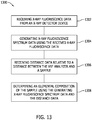
- FIG. 13 is a flow chart of a method 1300 of processing X-ray fluorescence data in a hand-held X-ray Fluorescence (XRF) analyzer.
- the method is implemented using a computer device coupled to a memory device.
- method 1300 includes receiving 1302 X-ray fluorescence data from an X-ray detector device, generating 1304 X-ray fluorescence spectrum data using the received X-ray fluorescence data, receiving 1306 distance data relative to a distance between the XRF analyzer and a sample, and determining 1308 an elemental composition of the sample using the generated X-ray fluorescence spectrum data and the distance data.
- processor refers to central processing units, microprocessors, microcontrollers, reduced instruction set circuits (RISC), application specific integrated circuits (ASIC), logic circuits, and any other circuit or processor capable of executing the functions described herein.
- RISC reduced instruction set circuits
- ASIC application specific integrated circuits
- the terms "software” and “firmware” are interchangeable, and include any computer program stored in memory for execution by mobile devices, clusters, personal computers, workstations, clients, servers, and processors wherein the memory includes RAM memory, ROM memory, EPROM memory, EEPROM memory, and non-volatile RAM (NVRAM) memory.
- RAM random access memory
- ROM memory read-only memory
- EPROM memory erasable programmable read-only memory
- EEPROM memory electrically erasable programmable read-only memory
- NVRAM non-volatile RAM
- the above-discussed embodiments of the disclosure may be implemented using computer programming or engineering techniques including computer software, firmware, hardware or any combination or subset thereof. Any such resulting program, having computer-readable and/or computer-executable instructions, may be embodied or provided within one or more computer-readable media, thereby making a computer program product, i.e., an article of manufacture, according to the discussed embodiments of the disclosure.
- the computer readable media may be, for instance, a fixed (hard) drive, diskette, optical disk, magnetic tape, semiconductor memory such as read-only memory (ROM) or flash memory, etc., or any transmitting/receiving medium such as the Internet or other communication network or link.
- the article of manufacture containing the computer code may be made and/or used by executing the instructions directly from one medium, by copying the code from one medium to another medium, or by transmitting the code over a network.
- the technical effect of the methods and systems may be achieved by performing at least one of the following steps: (a) filtering a stream of X-rays using a plurality of filters arranged in series in a path of the stream of X-rays, (b) reducing Bragg reflections using the beam geometry defined by the relative physical positons and directional positions of the radiation source assembly and radiation detector assembly, (c) removably mounting auxiliary analyzers and support components on a quick-change instrument rail, (d) continuously monitoring a distance of the faceplate of the analyzer to the sample to be tested and providing a distance indication to the user and using the distance indication in analyzing the sample data, and (e) wirelessly communicating between the XRF analyzer and an offboard processor to perform analysis of sample data in real-time during a test of a sample.
- non-transitory computer-readable media is intended to be representative of any tangible computer-based device implemented in any method or technology for short-term and long-term storage of information, such as, computer-readable instructions, data structures, program modules and sub-modules, or other data in any device. Therefore, the methods described herein may be encoded as executable instructions embodied in a tangible, non-transitory, computer readable medium, including, without limitation, a storage device and/or a memory device. Such instructions, when executed by a processor, cause the processor to perform at least a portion of the methods described herein.
- non-transitory computer-readable media includes all tangible, computer-readable media, including, without limitation, non-transitory computer storage devices, including, without limitation, volatile and nonvolatile media, and removable and non-removable media such as a firmware, physical and virtual storage, CD-ROMs, DVDs, and any other digital source such as a network or the Internet, as well as yet to be developed digital means, with the sole exception being a transitory, propagating signal.
- the term "computer” and related terms, e.g., “computing device”, are not limited to integrated circuits referred to in the art as a computer, but broadly refers to a microcontroller, a microcomputer, a programmable logic controller (PLC), an application specific integrated circuit, and other programmable circuits, and these terms are used interchangeably herein.
- PLC programmable logic controller
- cloud computing and related terms, e.g., “cloud computing devices” refers to a computer architecture allowing for the use of multiple heterogeneous computing devices for data storage, retrieval, and processing.
- the heterogeneous computing devices may use a common network or a plurality of networks so that some computing devices are in networked communication with one another over a common network but not all computing devices.
- a plurality of networks may be used in order to facilitate the communication between and coordination of all computing devices.
- mobile computing device refers to any of computing device which is used in a portable manner including, without limitation, smart phones, personal digital assistants ("PDAs”), computer tablets, hybrid phone/computer tablets (“phablet”), or other similar mobile device capable of functioning in the systems described herein.
- mobile computing devices may include a variety of peripherals and accessories including, without limitation, microphones, speakers, keyboards, touchscreens, gyroscopes, accelerometers, and metrological devices.
- portable computing device and “mobile computing device” may be used interchangeably.
Landscapes
- Physics & Mathematics (AREA)
- Health & Medical Sciences (AREA)
- Life Sciences & Earth Sciences (AREA)
- Chemical & Material Sciences (AREA)
- Analytical Chemistry (AREA)
- Biochemistry (AREA)
- General Health & Medical Sciences (AREA)
- General Physics & Mathematics (AREA)
- Immunology (AREA)
- Pathology (AREA)
- Analysing Materials By The Use Of Radiation (AREA)
Applications Claiming Priority (2)
| Application Number | Priority Date | Filing Date | Title |
|---|---|---|---|
| US201662368256P | 2016-07-29 | 2016-07-29 | |
| US15/661,201 US10641718B2 (en) | 2016-07-29 | 2017-07-27 | X-ray fluorescence analyzer |
Publications (3)
| Publication Number | Publication Date |
|---|---|
| EP3276338A2 true EP3276338A2 (de) | 2018-01-31 |
| EP3276338A3 EP3276338A3 (de) | 2018-03-21 |
| EP3276338B1 EP3276338B1 (de) | 2019-12-11 |
Family
ID=59485244
Family Applications (1)
| Application Number | Title | Priority Date | Filing Date |
|---|---|---|---|
| EP17183698.4A Active EP3276338B1 (de) | 2016-07-29 | 2017-07-28 | Röntgenfluoreszenzanalysator |
Country Status (2)
| Country | Link |
|---|---|
| US (1) | US10641718B2 (de) |
| EP (1) | EP3276338B1 (de) |
Cited By (3)
| Publication number | Priority date | Publication date | Assignee | Title |
|---|---|---|---|---|
| CN111189867A (zh) * | 2020-03-06 | 2020-05-22 | 张磊 | 土壤信息化综合管理平台系统 |
| EP4397968A1 (de) * | 2023-01-05 | 2024-07-10 | Fondis Electronic | Tragbares handspektrometerinstrument mit ergonomischer zeigevorrichtung |
| US12099516B2 (en) | 2019-09-16 | 2024-09-24 | Texas Tech University System | Data visualization device and method |
Families Citing this family (6)
| Publication number | Priority date | Publication date | Assignee | Title |
|---|---|---|---|---|
| WO2020034002A1 (en) * | 2018-08-17 | 2020-02-20 | Microtrace Pty Limited | Apparatus for the measurement of mineral slurries |
| US11747290B2 (en) | 2019-02-27 | 2023-09-05 | Li Industries, Inc. | Methods and systems for smart battery collection, sorting, and packaging |
| JP7544140B2 (ja) * | 2020-11-12 | 2024-09-03 | 株式会社島津製作所 | 蛍光x線分析装置 |
| PE20260594A1 (es) * | 2023-05-26 | 2026-03-11 | Veracio Ltd | Montaje para fluorescencia de rayos x y sistemas y metodos que los comprenden |
| EP4563989A1 (de) * | 2023-11-29 | 2025-06-04 | Bruker Nano GmbH | Handhaltbarer röntgenfluoreszenz-, röntgenrf-analysator und verfahren zur elementaranalyse mit einem handhaltbaren röntgenrf-analysator |
| WO2026156073A1 (en) * | 2025-01-14 | 2026-07-23 | Viken Detection Corporation | X-ray scanning with passive radiation detection |
Family Cites Families (26)
| Publication number | Priority date | Publication date | Assignee | Title |
|---|---|---|---|---|
| JP2001349853A (ja) | 2000-04-06 | 2001-12-21 | Seiko Instruments Inc | 可搬型蛍光x線分析計 |
| JP4933702B2 (ja) | 2000-04-06 | 2012-05-16 | エスアイアイ・ナノテクノロジー株式会社 | 可搬型蛍光x線分析計 |
| JP2002039975A (ja) | 2000-07-27 | 2002-02-06 | Seiko Instruments Inc | 蛍光x線分析計 |
| JP2002039973A (ja) | 2000-07-27 | 2002-02-06 | Seiko Instruments Inc | 蛍光x線分析計 |
| US6765986B2 (en) | 2001-02-08 | 2004-07-20 | Niton Corporation | X-ray fluorescence analyzer |
| KR20030041724A (ko) | 2001-11-21 | 2003-05-27 | 주식회사 포스코 | 레이저와 미니엑스레이를 이용한 휴대용 도금량 측정장치 |
| JP2004184314A (ja) * | 2002-12-05 | 2004-07-02 | Mitsubishi Electric Corp | 蛍光x線分析装置 |
| US7020238B1 (en) | 2005-01-31 | 2006-03-28 | Oxford Instruments Analytical Oy | Adapter and analyzer device for performing X-ray fluorescence analysis on hot surfaces |
| US7409037B2 (en) | 2006-05-05 | 2008-08-05 | Oxford Instruments Analytical Oy | X-ray fluorescence analyzer having means for producing lowered pressure, and an X-ray fluorescence measurement method using lowered pressure |
| US7443959B2 (en) | 2006-10-10 | 2008-10-28 | Oxford Instruments Analytical Oy | Selective irradiation of small target area in X-ray fluorescent spectroscopy |
| US7916834B2 (en) * | 2007-02-12 | 2011-03-29 | Thermo Niton Analyzers Llc | Small spot X-ray fluorescence (XRF) analyzer |
| US7508906B2 (en) | 2007-04-26 | 2009-03-24 | Oxford Instruments Analytical Oy | Filter for X-ray radiation, and an arrangement for using filtered X-ray radiation for excitation |
| KR100899011B1 (ko) | 2007-05-04 | 2009-05-21 | (주) 브이에스아이 | 카메라모듈과 반사형 근접센서를 이용한 휴대용 엑스선형광 금속분석장치 및 금속분석방법 |
| WO2009032640A2 (en) | 2007-08-28 | 2009-03-12 | Thermo Niton Analyzers Llc | Contactless memory information storage for sample analysis and hand-holdable analyzer for use therewith |
| WO2009134924A1 (en) * | 2008-04-30 | 2009-11-05 | Thermo Niton Analyzers Llc | In vivo measurement of trace elements in bone by x-ray fluorescence |
| US8559669B2 (en) * | 2010-03-01 | 2013-10-15 | Cubic Corporation | Security polymer threat detection distribution system |
| CN102507625A (zh) | 2011-11-22 | 2012-06-20 | 南京华欣分析仪器制造有限公司 | 一种x射线荧光光谱仪的测量设置结构 |
| GB201213789D0 (en) | 2012-08-02 | 2012-09-12 | Commw Scient Ind Res Org | An X-ray fluorescence analyser |
| US9222769B2 (en) * | 2012-12-08 | 2015-12-29 | Grale Technologies | High speed metrology with numerically controlled machines |
| US9310324B2 (en) | 2013-09-24 | 2016-04-12 | Oxford Instruments Analytical Oy | X-ray fluorescence analyzer with safety features |
| US9551677B2 (en) * | 2014-01-21 | 2017-01-24 | Bruker Jv Israel Ltd. | Angle calibration for grazing-incidence X-ray fluorescence (GIXRF) |
| EP2908127B1 (de) | 2014-02-18 | 2017-07-05 | PANalytical B.V. | Röntgenanalysevorrichtung mit Robotarm |
| EP2927948A1 (de) * | 2014-04-04 | 2015-10-07 | Nordson Corporation | Röntgeninspektionsvorrichtung zum Prüfen von Halbleiter-Wafern |
| US9689815B2 (en) | 2014-09-12 | 2017-06-27 | Moxtek, Inc. | XRF analyzer rotational filter |
| US10207296B2 (en) * | 2015-07-16 | 2019-02-19 | UHV Technologies, Inc. | Material sorting system |
| WO2017024035A1 (en) * | 2015-08-03 | 2017-02-09 | UHV Technologies, Inc. | Metal analysis during pharmaceutical manufacturing |
-
2017
- 2017-07-27 US US15/661,201 patent/US10641718B2/en active Active
- 2017-07-28 EP EP17183698.4A patent/EP3276338B1/de active Active
Non-Patent Citations (1)
| Title |
|---|
| None |
Cited By (4)
| Publication number | Priority date | Publication date | Assignee | Title |
|---|---|---|---|---|
| US12099516B2 (en) | 2019-09-16 | 2024-09-24 | Texas Tech University System | Data visualization device and method |
| CN111189867A (zh) * | 2020-03-06 | 2020-05-22 | 张磊 | 土壤信息化综合管理平台系统 |
| CN111189867B (zh) * | 2020-03-06 | 2023-04-11 | 张磊 | 土壤信息化综合管理平台系统 |
| EP4397968A1 (de) * | 2023-01-05 | 2024-07-10 | Fondis Electronic | Tragbares handspektrometerinstrument mit ergonomischer zeigevorrichtung |
Also Published As
| Publication number | Publication date |
|---|---|
| US20180031497A1 (en) | 2018-02-01 |
| EP3276338B1 (de) | 2019-12-11 |
| EP3276338A3 (de) | 2018-03-21 |
| US10641718B2 (en) | 2020-05-05 |
Similar Documents
| Publication | Publication Date | Title |
|---|---|---|
| US10641718B2 (en) | X-ray fluorescence analyzer | |
| US11796490B2 (en) | X-ray spectrometer and methods for use | |
| EP2839498B1 (de) | Vorrichtung zum schutz eines strahlungsfensters | |
| Yan et al. | Online X-ray fluorescence (XRF) analysis of heavy metals in pulverized coal on a conveyor belt | |
| JP6309583B2 (ja) | 表面の化学的性質の非接触測定装置および方法 | |
| US9739727B2 (en) | Systems and methods for aligning an aperture | |
| US10948435B2 (en) | X-ray fluorescence analysis device, and spectrum display method used in same | |
| US20120084016A1 (en) | Portable laser-induced breakdown spectroscopy system with modularized reference data | |
| Qing et al. | Development of an online X-ray fluorescence analysis system for heavy metals measurement in cement raw meal | |
| WO2018020565A1 (ja) | 置換サイト計測装置および置換サイト計測方法 | |
| US20160061753A1 (en) | X-ray fluorescence analyzer and method of displaying sample thereof | |
| EP2881973A1 (de) | Vorrichtung und Verfahren für PVD-Verfahrensdiagnose unter Verwendung einer lokalen Röntgenfluoreszenzsonde | |
| Vavryčuk et al. | The failure of testing for cosmic opacity via the distance-duality relation | |
| EP3553502A1 (de) | Kontaktloses sicherheitsüberprüfungssystem und verfahren | |
| JP6113524B2 (ja) | モニタリングカート | |
| Davis et al. | Bridging the micro-to-macro gap: a new application for micro X-ray fluorescence | |
| JP2008309742A (ja) | 蛍光x線分析装置 | |
| US20210199606A1 (en) | Measurement system, program, and measurement system control method | |
| JP2018200245A (ja) | 蛍光x線分析装置 | |
| JP2001264272A (ja) | 陽電子消滅γ線測定方法および装置 | |
| US20250290876A1 (en) | Fluorescent x-ray analysis device | |
| US20160231438A1 (en) | System for measuring radioactivity in a gamma background noise | |
| Finocchiaro | The IMAT imaging camera | |
| Polese et al. | 2D and 3D micro-XRF based on polycapillary optics at XLab Frascati | |
| JP4255012B2 (ja) | 蛍光x線分析装置 |
Legal Events
| Date | Code | Title | Description |
|---|---|---|---|
| PUAI | Public reference made under article 153(3) epc to a published international application that has entered the european phase |
Free format text: ORIGINAL CODE: 0009012 |
|
| STAA | Information on the status of an ep patent application or granted ep patent |
Free format text: STATUS: THE APPLICATION HAS BEEN PUBLISHED |
|
| AK | Designated contracting states |
Kind code of ref document: A2 Designated state(s): AL AT BE BG CH CY CZ DE DK EE ES FI FR GB GR HR HU IE IS IT LI LT LU LV MC MK MT NL NO PL PT RO RS SE SI SK SM TR |
|
| AX | Request for extension of the european patent |
Extension state: BA ME |
|
| PUAL | Search report despatched |
Free format text: ORIGINAL CODE: 0009013 |
|
| AK | Designated contracting states |
Kind code of ref document: A3 Designated state(s): AL AT BE BG CH CY CZ DE DK EE ES FI FR GB GR HR HU IE IS IT LI LT LU LV MC MK MT NL NO PL PT RO RS SE SI SK SM TR |
|
| AX | Request for extension of the european patent |
Extension state: BA ME |
|
| RIC1 | Information provided on ipc code assigned before grant |
Ipc: G01N 23/223 20060101AFI20180214BHEP |
|
| STAA | Information on the status of an ep patent application or granted ep patent |
Free format text: STATUS: REQUEST FOR EXAMINATION WAS MADE |
|
| 17P | Request for examination filed |
Effective date: 20180829 |
|
| RBV | Designated contracting states (corrected) |
Designated state(s): AL AT BE BG CH CY CZ DE DK EE ES FI FR GB GR HR HU IE IS IT LI LT LU LV MC MK MT NL NO PL PT RO RS SE SI SK SM TR |
|
| STAA | Information on the status of an ep patent application or granted ep patent |
Free format text: STATUS: EXAMINATION IS IN PROGRESS |
|
| 17Q | First examination report despatched |
Effective date: 20190318 |
|
| GRAP | Despatch of communication of intention to grant a patent |
Free format text: ORIGINAL CODE: EPIDOSNIGR1 |
|
| STAA | Information on the status of an ep patent application or granted ep patent |
Free format text: STATUS: GRANT OF PATENT IS INTENDED |
|
| INTG | Intention to grant announced |
Effective date: 20190731 |
|
| GRAS | Grant fee paid |
Free format text: ORIGINAL CODE: EPIDOSNIGR3 |
|
| GRAA | (expected) grant |
Free format text: ORIGINAL CODE: 0009210 |
|
| STAA | Information on the status of an ep patent application or granted ep patent |
Free format text: STATUS: THE PATENT HAS BEEN GRANTED |
|
| AK | Designated contracting states |
Kind code of ref document: B1 Designated state(s): AL AT BE BG CH CY CZ DE DK EE ES FI FR GB GR HR HU IE IS IT LI LT LU LV MC MK MT NL NO PL PT RO RS SE SI SK SM TR |
|
| REG | Reference to a national code |
Ref country code: GB Ref legal event code: FG4D |
|
| REG | Reference to a national code |
Ref country code: CH Ref legal event code: EP |
|
| REG | Reference to a national code |
Ref country code: AT Ref legal event code: REF Ref document number: 1212684 Country of ref document: AT Kind code of ref document: T Effective date: 20191215 |
|
| REG | Reference to a national code |
Ref country code: DE Ref legal event code: R096 Ref document number: 602017009534 Country of ref document: DE |
|
| REG | Reference to a national code |
Ref country code: IE Ref legal event code: FG4D |
|
| REG | Reference to a national code |
Ref country code: DE Ref legal event code: R082 Ref document number: 602017009534 Country of ref document: DE Representative=s name: WITTHOFF JAEKEL STEINECKE PATENTANWAELTE PARTG, DE |
|
| REG | Reference to a national code |
Ref country code: NL Ref legal event code: MP Effective date: 20191211 |
|
| REG | Reference to a national code |
Ref country code: LT Ref legal event code: MG4D |
|
| PG25 | Lapsed in a contracting state [announced via postgrant information from national office to epo] |
Ref country code: GR Free format text: LAPSE BECAUSE OF FAILURE TO SUBMIT A TRANSLATION OF THE DESCRIPTION OR TO PAY THE FEE WITHIN THE PRESCRIBED TIME-LIMIT Effective date: 20200312 Ref country code: FI Free format text: LAPSE BECAUSE OF FAILURE TO SUBMIT A TRANSLATION OF THE DESCRIPTION OR TO PAY THE FEE WITHIN THE PRESCRIBED TIME-LIMIT Effective date: 20191211 Ref country code: BG Free format text: LAPSE BECAUSE OF FAILURE TO SUBMIT A TRANSLATION OF THE DESCRIPTION OR TO PAY THE FEE WITHIN THE PRESCRIBED TIME-LIMIT Effective date: 20200311 Ref country code: LT Free format text: LAPSE BECAUSE OF FAILURE TO SUBMIT A TRANSLATION OF THE DESCRIPTION OR TO PAY THE FEE WITHIN THE PRESCRIBED TIME-LIMIT Effective date: 20191211 Ref country code: SE Free format text: LAPSE BECAUSE OF FAILURE TO SUBMIT A TRANSLATION OF THE DESCRIPTION OR TO PAY THE FEE WITHIN THE PRESCRIBED TIME-LIMIT Effective date: 20191211 Ref country code: LV Free format text: LAPSE BECAUSE OF FAILURE TO SUBMIT A TRANSLATION OF THE DESCRIPTION OR TO PAY THE FEE WITHIN THE PRESCRIBED TIME-LIMIT Effective date: 20191211 Ref country code: NO Free format text: LAPSE BECAUSE OF FAILURE TO SUBMIT A TRANSLATION OF THE DESCRIPTION OR TO PAY THE FEE WITHIN THE PRESCRIBED TIME-LIMIT Effective date: 20200311 |
|
| PG25 | Lapsed in a contracting state [announced via postgrant information from national office to epo] |
Ref country code: HR Free format text: LAPSE BECAUSE OF FAILURE TO SUBMIT A TRANSLATION OF THE DESCRIPTION OR TO PAY THE FEE WITHIN THE PRESCRIBED TIME-LIMIT Effective date: 20191211 Ref country code: RS Free format text: LAPSE BECAUSE OF FAILURE TO SUBMIT A TRANSLATION OF THE DESCRIPTION OR TO PAY THE FEE WITHIN THE PRESCRIBED TIME-LIMIT Effective date: 20191211 |
|
| PG25 | Lapsed in a contracting state [announced via postgrant information from national office to epo] |
Ref country code: AL Free format text: LAPSE BECAUSE OF FAILURE TO SUBMIT A TRANSLATION OF THE DESCRIPTION OR TO PAY THE FEE WITHIN THE PRESCRIBED TIME-LIMIT Effective date: 20191211 |
|
| REG | Reference to a national code |
Ref country code: DE Ref legal event code: R081 Ref document number: 602017009534 Country of ref document: DE Owner name: BRUKER AXS LLC, MADISON, US Free format text: FORMER OWNER: BRUKER AXS HANDHELD, INC., KENNEWICK, WASH., US Ref country code: DE Ref legal event code: R082 Ref document number: 602017009534 Country of ref document: DE Representative=s name: WITTHOFF JAEKEL STEINECKE PATENTANWAELTE PARTG, DE Ref country code: DE Ref legal event code: R081 Ref document number: 602017009534 Country of ref document: DE Owner name: BRUKER HANDHELD LLC (N.D.GES.D.STAATES DELAWAR, US Free format text: FORMER OWNER: BRUKER AXS HANDHELD, INC., KENNEWICK, WASH., US |
|
| PG25 | Lapsed in a contracting state [announced via postgrant information from national office to epo] |
Ref country code: ES Free format text: LAPSE BECAUSE OF FAILURE TO SUBMIT A TRANSLATION OF THE DESCRIPTION OR TO PAY THE FEE WITHIN THE PRESCRIBED TIME-LIMIT Effective date: 20191211 Ref country code: PT Free format text: LAPSE BECAUSE OF FAILURE TO SUBMIT A TRANSLATION OF THE DESCRIPTION OR TO PAY THE FEE WITHIN THE PRESCRIBED TIME-LIMIT Effective date: 20200506 Ref country code: EE Free format text: LAPSE BECAUSE OF FAILURE TO SUBMIT A TRANSLATION OF THE DESCRIPTION OR TO PAY THE FEE WITHIN THE PRESCRIBED TIME-LIMIT Effective date: 20191211 Ref country code: NL Free format text: LAPSE BECAUSE OF FAILURE TO SUBMIT A TRANSLATION OF THE DESCRIPTION OR TO PAY THE FEE WITHIN THE PRESCRIBED TIME-LIMIT Effective date: 20191211 Ref country code: RO Free format text: LAPSE BECAUSE OF FAILURE TO SUBMIT A TRANSLATION OF THE DESCRIPTION OR TO PAY THE FEE WITHIN THE PRESCRIBED TIME-LIMIT Effective date: 20191211 Ref country code: CZ Free format text: LAPSE BECAUSE OF FAILURE TO SUBMIT A TRANSLATION OF THE DESCRIPTION OR TO PAY THE FEE WITHIN THE PRESCRIBED TIME-LIMIT Effective date: 20191211 |
|
| PG25 | Lapsed in a contracting state [announced via postgrant information from national office to epo] |
Ref country code: SM Free format text: LAPSE BECAUSE OF FAILURE TO SUBMIT A TRANSLATION OF THE DESCRIPTION OR TO PAY THE FEE WITHIN THE PRESCRIBED TIME-LIMIT Effective date: 20191211 Ref country code: SK Free format text: LAPSE BECAUSE OF FAILURE TO SUBMIT A TRANSLATION OF THE DESCRIPTION OR TO PAY THE FEE WITHIN THE PRESCRIBED TIME-LIMIT Effective date: 20191211 Ref country code: IS Free format text: LAPSE BECAUSE OF FAILURE TO SUBMIT A TRANSLATION OF THE DESCRIPTION OR TO PAY THE FEE WITHIN THE PRESCRIBED TIME-LIMIT Effective date: 20200411 |
|
| RAP2 | Party data changed (patent owner data changed or rights of a patent transferred) |
Owner name: BRUKER HANDHELD LLC |
|
| REG | Reference to a national code |
Ref country code: DE Ref legal event code: R097 Ref document number: 602017009534 Country of ref document: DE |
|
| REG | Reference to a national code |
Ref country code: AT Ref legal event code: MK05 Ref document number: 1212684 Country of ref document: AT Kind code of ref document: T Effective date: 20191211 |
|
| PLBE | No opposition filed within time limit |
Free format text: ORIGINAL CODE: 0009261 |
|
| STAA | Information on the status of an ep patent application or granted ep patent |
Free format text: STATUS: NO OPPOSITION FILED WITHIN TIME LIMIT |
|
| PG25 | Lapsed in a contracting state [announced via postgrant information from national office to epo] |
Ref country code: DK Free format text: LAPSE BECAUSE OF FAILURE TO SUBMIT A TRANSLATION OF THE DESCRIPTION OR TO PAY THE FEE WITHIN THE PRESCRIBED TIME-LIMIT Effective date: 20191211 |
|
| 26N | No opposition filed |
Effective date: 20200914 |
|
| PG25 | Lapsed in a contracting state [announced via postgrant information from national office to epo] |
Ref country code: AT Free format text: LAPSE BECAUSE OF FAILURE TO SUBMIT A TRANSLATION OF THE DESCRIPTION OR TO PAY THE FEE WITHIN THE PRESCRIBED TIME-LIMIT Effective date: 20191211 Ref country code: SI Free format text: LAPSE BECAUSE OF FAILURE TO SUBMIT A TRANSLATION OF THE DESCRIPTION OR TO PAY THE FEE WITHIN THE PRESCRIBED TIME-LIMIT Effective date: 20191211 |
|
| PG25 | Lapsed in a contracting state [announced via postgrant information from national office to epo] |
Ref country code: IT Free format text: LAPSE BECAUSE OF FAILURE TO SUBMIT A TRANSLATION OF THE DESCRIPTION OR TO PAY THE FEE WITHIN THE PRESCRIBED TIME-LIMIT Effective date: 20191211 |
|
| PG25 | Lapsed in a contracting state [announced via postgrant information from national office to epo] |
Ref country code: PL Free format text: LAPSE BECAUSE OF FAILURE TO SUBMIT A TRANSLATION OF THE DESCRIPTION OR TO PAY THE FEE WITHIN THE PRESCRIBED TIME-LIMIT Effective date: 20191211 Ref country code: MC Free format text: LAPSE BECAUSE OF FAILURE TO SUBMIT A TRANSLATION OF THE DESCRIPTION OR TO PAY THE FEE WITHIN THE PRESCRIBED TIME-LIMIT Effective date: 20191211 |
|
| REG | Reference to a national code |
Ref country code: CH Ref legal event code: PL |
|
| REG | Reference to a national code |
Ref country code: BE Ref legal event code: MM Effective date: 20200731 |
|
| PG25 | Lapsed in a contracting state [announced via postgrant information from national office to epo] |
Ref country code: CH Free format text: LAPSE BECAUSE OF NON-PAYMENT OF DUE FEES Effective date: 20200731 Ref country code: LU Free format text: LAPSE BECAUSE OF NON-PAYMENT OF DUE FEES Effective date: 20200728 Ref country code: LI Free format text: LAPSE BECAUSE OF NON-PAYMENT OF DUE FEES Effective date: 20200731 |
|
| PG25 | Lapsed in a contracting state [announced via postgrant information from national office to epo] |
Ref country code: BE Free format text: LAPSE BECAUSE OF NON-PAYMENT OF DUE FEES Effective date: 20200731 |
|
| PG25 | Lapsed in a contracting state [announced via postgrant information from national office to epo] |
Ref country code: IE Free format text: LAPSE BECAUSE OF NON-PAYMENT OF DUE FEES Effective date: 20200728 |
|
| REG | Reference to a national code |
Ref country code: DE Ref legal event code: R081 Ref document number: 602017009534 Country of ref document: DE Owner name: BRUKER AXS LLC, MADISON, US Free format text: FORMER OWNER: BRUKER HANDHELD LLC (N.D.GES.D.STAATES DELAWARE), KENNEWICK, WA, US |
|
| REG | Reference to a national code |
Ref country code: GB Ref legal event code: 732E Free format text: REGISTERED BETWEEN 20220428 AND 20220504 |
|
| PG25 | Lapsed in a contracting state [announced via postgrant information from national office to epo] |
Ref country code: TR Free format text: LAPSE BECAUSE OF FAILURE TO SUBMIT A TRANSLATION OF THE DESCRIPTION OR TO PAY THE FEE WITHIN THE PRESCRIBED TIME-LIMIT Effective date: 20191211 Ref country code: MT Free format text: LAPSE BECAUSE OF FAILURE TO SUBMIT A TRANSLATION OF THE DESCRIPTION OR TO PAY THE FEE WITHIN THE PRESCRIBED TIME-LIMIT Effective date: 20191211 Ref country code: CY Free format text: LAPSE BECAUSE OF FAILURE TO SUBMIT A TRANSLATION OF THE DESCRIPTION OR TO PAY THE FEE WITHIN THE PRESCRIBED TIME-LIMIT Effective date: 20191211 |
|
| PG25 | Lapsed in a contracting state [announced via postgrant information from national office to epo] |
Ref country code: MK Free format text: LAPSE BECAUSE OF FAILURE TO SUBMIT A TRANSLATION OF THE DESCRIPTION OR TO PAY THE FEE WITHIN THE PRESCRIBED TIME-LIMIT Effective date: 20191211 |
|
| PGFP | Annual fee paid to national office [announced via postgrant information from national office to epo] |
Ref country code: DE Payment date: 20250729 Year of fee payment: 9 |
|
| PGFP | Annual fee paid to national office [announced via postgrant information from national office to epo] |
Ref country code: GB Payment date: 20250728 Year of fee payment: 9 |
|
| PGFP | Annual fee paid to national office [announced via postgrant information from national office to epo] |
Ref country code: FR Payment date: 20250728 Year of fee payment: 9 |