EP3276384A1 - Mehradrige glasfaser - Google Patents
Mehradrige glasfaser Download PDFInfo
- Publication number
- EP3276384A1 EP3276384A1 EP16768410.9A EP16768410A EP3276384A1 EP 3276384 A1 EP3276384 A1 EP 3276384A1 EP 16768410 A EP16768410 A EP 16768410A EP 3276384 A1 EP3276384 A1 EP 3276384A1
- Authority
- EP
- European Patent Office
- Prior art keywords
- core
- cores
- alkali metal
- mcf
- less
- Prior art date
- Legal status (The legal status is an assumption and is not a legal conclusion. Google has not performed a legal analysis and makes no representation as to the accuracy of the status listed.)
- Granted
Links
Images


Classifications
-
- G—PHYSICS
- G02—OPTICS
- G02B—OPTICAL ELEMENTS, SYSTEMS OR APPARATUS
- G02B6/00—Light guides; Structural details of arrangements comprising light guides and other optical elements, e.g. couplings
- G02B6/02—Optical fibres with cladding with or without a coating
- G02B6/02042—Multicore optical fibres
-
- G—PHYSICS
- G02—OPTICS
- G02B—OPTICAL ELEMENTS, SYSTEMS OR APPARATUS
- G02B6/00—Light guides; Structural details of arrangements comprising light guides and other optical elements, e.g. couplings
- G02B6/02—Optical fibres with cladding with or without a coating
- G02B6/02004—Optical fibres with cladding with or without a coating characterised by the core effective area or mode field radius
-
- G—PHYSICS
- G02—OPTICS
- G02B—OPTICAL ELEMENTS, SYSTEMS OR APPARATUS
- G02B6/00—Light guides; Structural details of arrangements comprising light guides and other optical elements, e.g. couplings
- G02B6/02—Optical fibres with cladding with or without a coating
- G02B6/02214—Optical fibres with cladding with or without a coating tailored to obtain the desired dispersion, e.g. dispersion shifted, dispersion flattened
-
- G—PHYSICS
- G02—OPTICS
- G02B—OPTICAL ELEMENTS, SYSTEMS OR APPARATUS
- G02B6/00—Light guides; Structural details of arrangements comprising light guides and other optical elements, e.g. couplings
- G02B6/02—Optical fibres with cladding with or without a coating
- G02B6/036—Optical fibres with cladding with or without a coating core or cladding comprising multiple layers
- G02B6/03616—Optical fibres characterised both by the number of different refractive index layers around the central core segment, i.e. around the innermost high index core layer, and their relative refractive index difference
-
- G—PHYSICS
- G02—OPTICS
- G02B—OPTICAL ELEMENTS, SYSTEMS OR APPARATUS
- G02B6/00—Light guides; Structural details of arrangements comprising light guides and other optical elements, e.g. couplings
- G02B6/24—Coupling light guides
- G02B6/36—Mechanical coupling means
- G02B6/38—Mechanical coupling means having fibre to fibre mating means
- G02B6/3807—Dismountable connectors, i.e. comprising plugs
- G02B6/3873—Connectors using guide surfaces for aligning ferrule ends, e.g. tubes, sleeves, V-grooves, rods, pins, balls
- G02B6/3885—Multicore or multichannel optical connectors, i.e. one single ferrule containing more than one fibre, e.g. ribbon type
Definitions
- the present invention relates to a multicore optical fiber of an uncoupled type (referred to as MCF below).
- Patent Document 1 discloses a technique for reducing a transmission loss of a MCF of which a plurality of cores is made of pure silica glass
- Patent Document 2 discloses a technique for reducing the transmission loss by adding alkali metal to the core
- Patent Document 3 discloses a structure in which each single core fiber is easily separated by employing glass in which alkali metal that is easily melted by an acid or the like is doped in glass for covering the outermost peripheral face of a plurality of single core fibers constituting a bunch fiber.
- a transmission loss of the MCF manufactured by the Stack and Draw process is described in Non-Patent Document 1
- a transmission loss of the MCF manufactured by the rod-in-collapse method is described in Non-Patent Document 2.
- the present invention has been made to solve the above problems.
- An object of the present invention to provide an uncoupled MCF having a structure for reducing a transmission loss and effectively suppressing an inter-core XT.
- the MCF according to the present embodiment is an uncoupled MCF that enables single mode transmission in individual cores, and includes a plurality of cores respectively extending in predetermined directions and a cladding for covering the plurality of cores.
- each of the plurality of cores includes alkali metal having a concentration sufficient for reducing the loss.
- a core pitch defined by the shortest distance between the centers of the adjacent cores of the plurality of cores is set so that the sum h_total of power coupling coefficients of a specific core and the remaining all cores of the plurality of cores is 2.3 ⁇ 10 -4 /km or less.
- Fig. 1A is a diagram of a sectional structure of a preform 100A before drawing to manufacture an MCF 200A according to a first embodiment.
- the cross section illustrated in Fig. 1A is a cross section orthogonal to a central axis AX (coincide with a longitudinal direction of the preform 100A) of the preform 100A, and the preform 100A includes core parts 110 extending along the central axis AX and a cladding part 120 for covering each of the core parts 110.
- the MCF 200A is obtained by drawing the preform 100A, and the sectional structure thereof is similar to the sectional structure of the preform 100A.
- the core 210 of the MCF 200A obtained by drawing the preform 100A corresponds to the core part 110 of the preform 100A
- the cladding 220 of the MCF 200A corresponds to the cladding part 120 of the preform 100A.
- Fig. 1B is a diagram of a refractive index profile 150A and an alkali metal concentration distribution 160A of the preform 100A along a line L (line orthogonal to central axis AX) in Fig. 1A .
- each core part 110 of the preform 100A is an alkali metal doped region in which alkali metal is doped.
- Fig. 1C is a diagram of a refractive index profile 250A and an alkali metal concentration distribution 260A of the MCF 200A according to the present embodiment obtained by drawing the preform 100A, and similarly to Fig. 1B, Fig. 1C is a profile along the line L in Fig. 1A .
- the alkali metal in each core part 110 is mutually diffused by being heated during drawing. Therefore, as illustrated in Fig. 1C , the alkali metal concentration in each core 210 in the MCF 200A after drawing decreases.
- the core pitch Acore becomes shorter, the alkali metal diffused from a certain core flows into the adjacent core so that reduction in the concentration of the alkali metal is eased and relaxation of a glass structure can be promoted. Therefore, in the MCF 200A according to the present embodiment, a transmission loss can be reduced. At this time, to efficiently diffuse the alkali metal between the cores 210, it is preferable that the distance between the cores be short. On the other hand, in a case where the inter-core XT is large, the transmission loss due to the inter-core XT is increased.
- Fig. 2 is a graph of a relationship between h_total (/ km) which is a sum of power coupling coefficients of a specific core and all the remaining cores of the plurality of cores included in the MCF and a transmission loss increment (dB/km) caused by the inter-core XT.
- h_total / km
- dB/km transmission loss increment
- the reference h is the power coupling coefficient
- h_total used in the present embodiment is the total sum of an efficiency of the optical power coupling from all the other cores to a single core.
- a leakage loss caused by the XT from one core to the other core can be suppressed to a value of 0.001 dB/km or less. That is, a region R2 illustrated in Fig. 2 represents a good range of the sum h_total of the power coupling coefficients that can effectively suppress the increase in the inter-core XT.
- the leakage loss caused by the inter-core XT from the core to the other core can be suppressed to a value of 0.0005 dB/km less.
- the reduction in the transmission loss due to the addition of the alkali metal depends on a drawing condition, for example, the concentration of the alkali metal such as potassium. However, reduction in the transmission loss of approximately 0.01 dB/km or more can be obtained.
- the additive concentration of the alkali metal in the core part 110 in the preform 100A before drawing is set so that the average concentration of alkali metal in each core 210 in the MCF 200A after drawing is 0.2 atom ppm or more and 50 atom ppm or less. This is because since crystallization of SiO 2 glass in which high concentration alkali metal has been doped is promoted, the relaxation of the glass structure of the core 210 can be promoted during drawing if the average value of the alkali metal included in each core 210 of the MCF 200A after drawing is 0.2 atom ppm or more.
- the transmission loss at the wavelength of 1550 nm after irradiation with radiation having a cumulative absorbed dose of 0.10 Gy or more is increased by 0.02 dB/km or more in comparison with that before the irradiation of the radiation, and this causes a problem in use in a system requiring stability of long-term transmission loss, such as a submarine system. Therefore, this is undesirable.
- a halogen element concentration in the core part 110 of the preform 100A is low, an effect to remove impurities by the halogen element in a preform manufacturing process cannot be sufficiently obtained, and the transmission loss is increased due to absorption of the impurities.
- the amount of the halogen element is too large, a halogen compound of alkali metal is generated and acts as a nucleus for crystal. Therefore, this is undesirable.
- the concentration of the halogen element such as Cl and F within a range of 1000 atom ppm to 3000 atom ppm, an MCF with a low transmission loss can be obtained without the above problem.
- a concentration of alkali metal on a glass surface (surface of cladding 220) of the MCF 200A after drawing is one atom ppm or less.
- the concentration of the alkali metal to the glass surface of the MCF 200A after drawing is preferably one atom ppm or less, and more preferably 0.1 atom ppm or less.
- potassium is diffused in a range of a radius of 15 to 50 ⁇ m after drawing.
- the diffusion radius depends on a potassium concentration at the preform stage and a temperature history during drawing. Therefore, it is desirable to determine a potassium addition position with respect to the core part 110 or the cladding part 120 in the cross section of the preform 100A after checking a potassium arrival distance after drawing in advance.
- the average concentration of the alkali metal element (for example, potassium) to be doped in the core part 110 of the preform 100A to reduce the transmission loss is five atom ppm or more, and suitably, 50 atom ppm or less.
- the time in which each position of the preform 100A is held at the 1500°C or higher in a drawing furnace is 110 minutes or shorter.
- a drawing speed is preferably 1200 m/min or more, and more preferably 1500 to 2300 m/min. It is preferable that the diameter of the preform 100A be 70 to 170 mm ⁇ , and more preferably, 90 to 150 mm ⁇ .
- the reason why this phenomenon is caused is considered as follows. That is, in a case where potassium with an average concentration of 500 atom ppm or less is included in the core part 110 of the preform 100A, a fictive temperature of the MCF 200A obtained from the preform 100A is 1400 to 1550°C, and the diffusion of potassium proceeds in the time from a peak temperature (1500°C or higher) to 1500°C in the drawing furnace.
- An alkali metal concentration of 0.2 atom ppm or more can be suitably realized in each core 210 of the MCF 200A after drawing by drawing from the preform 100A to the MCF 200A under such conditions.
- the MCF has the core which is substantially pure silica glass, to make the transmission loss fall below 0.170 dB/km, it is necessary for the time at which each position of the preform is held at a temperature of 1500°C or higher to be 110 minutes or shorter, and it is more preferable that the time be 70 minutes or shorter.
- the present embodiment can be obtained by suitably combining with annealing drawing which can maintain the temperature of the MCF during drawing to be equal to or more than a certain temperature and can promote the relaxation of the glass structure.
- annealing drawing which can maintain the temperature of the MCF during drawing to be equal to or more than a certain temperature and can promote the relaxation of the glass structure.
- a further lower transmission loss can be obtained.
- the method of the annealing drawing those skilled in the art can obtain appropriate manufacturing conditions necessary for reducing the transmission loss.
- atom ppm indicating the alkali concentration and the halogen concentration is the number of dopant atoms in the SiO 2 glass of one million units.
- the ratio of the number of K atoms and the number of SiO 2 molecules is indicated regardless of a bonding form in the SiO 2 glass.
- Li, Na, Rb, Cl, and F the same can be applied.
- various refractive index profiles can be applied to the region R1 (refer to Fig. 1A ) including each core 210 and a part of the cladding 220 around the core 210 of the MCF 200A having the above structure.
- each core 210 an appropriate structure can be selected according to the application.
- the structures of the respective cores 210 may be uniform or may be different from each other.
- the number of cores in the cross section of the MCF 200A is not limited, and the cross-sectional diameter (glass diameter) of the MCF 200A and the outer diameter of coating resin provided on the outer circumferential surface of the cladding 220 can be appropriately set according to the number of the stored cores.
- each core 210 may have a structure with a single mode operation of which the number of modes for propagating in the core is one and a structure with a multimode operation for propagating in the core in multiple modes.
- the transmission loss at the wavelength of 1550 nm in the core 210 is preferably 0.17 dB/km or less.
- the core is formed of SiO 2 glass to which GeO 2 molecules for increasing the refractive index of the core are not substantially doped, it is possible to suppress the transmission loss to be 0.17 dB/km or less since scattering caused by a concentration fluctuation of the GeO 2 molecules can be suppressed.
- a more preferable transmission loss is 0.165 dB/km or less.
- the transmission loss of each core at the wavelength of 1550 nm is preferably 0.18 dB/km or less.
- the core in which germanium has been doped generally has higher transmission loss than an optical fiber having a pure silica core.
- the scattering can be reduced by co-doping the alkali metal with the core. As a result, the transmission loss can be reduced.
- the alkali metal is doped in the core part in which germanium has been doped at the preform stage, crystals are likely to be generated in the core after drawing. Therefore, productivity is deteriorated.
- the alkali metal is not directly doped in the core part in which germanium has been doped, and the alkali metal is doped in the cladding part of the preform, and the alkali metal is diffused to the core according to the heating time at the time of drawing.
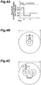
- optical characteristics of the plurality of samples and a comparative example of the MCF 200A according to the present embodiment are described in detail below with reference to Figs. 4A to 4C , 5A to 5C , and 6 .
- each of a MCF 1 (sample 1) and a MCF 2 (sample 2) has a cross-sectional structure having two cores as illustrated in Fig. 4C .
- the periphery of each core has the refractive index profile (ring type core + trench part) illustrated in Fig. 4A .
- the comparative example is a single core optical fiber (hereinafter referred to as SCF) having one core as illustrated in Fig. 4B , and the periphery of the core has the refractive index profile illustrated in Fig. 4A .
- a relative refractive index difference ⁇ 1 is 0.05%
- ⁇ 1' is - 0.05%
- ⁇ 2 is - 0.5%
- ⁇ 3 is - 0.25%
- the core diameter 2a is 12.51 ⁇ m
- the outer diameter 2b of the trench part is 34.61 ⁇ m
- the core pitch ⁇ core of the MCF 1 is 40.7 ⁇ m
- the core pitch Acore of the MCF 2 is 36.6 ⁇ m.
- a fiber outer diameter is 125 ⁇ m
- a drawing speed is 1500 m/min and a drawing tension is 80 to 100 g in drawing conditions.
- an average effective area A eff of each core at a wavelength of 1550 nm has been 110 ⁇ m 2 .
- the average potassium concentration in each core after drawing has been one atom ppm.
- Figs. 5A to 5C are charts of the optical characteristics of the MCF 1, the MCF 2, and the SCF.
- Fig. 5A as the optical characteristics of each of the MCF 1, the MCF 2, and the SCF at the wavelength of 1550 nm, the inter-core XT (dB) at a fiber length of 100 km, the sum of power coupling coefficients h_total (/ km), and the transmission loss (dB) caused by the inter-core XT are illustrated.
- Fig. 5A as the optical characteristics of each of the MCF 1, the MCF 2, and the SCF at the wavelength of 1550 nm, the inter-core XT (dB) at a fiber length of 100 km, the sum of power coupling coefficients h_total (/ km), and the transmission loss (dB) caused by the inter-core XT are illustrated.
- Fig. 5A as the optical characteristics of each of the MCF 1, the MCF 2, and the SCF at the wavelength of 1550 nm, the inter-
- the inter-core XT (dB) at a fiber length of 100 km, the sum of power coupling coefficients h_total (/ km), and the transmission loss (dB) caused by the inter-core XT are illustrated.
- the transmission loss (dB/km) at the wavelength of 1550 nm of the MCF 1, the MCF 2 and the SCF and the amount of the transmission loss reduction (dB/km) at the wavelength of 1550 nm are illustrated.
- the inter-core XT (dB) at the fiber length of 100 km is a measured value of the XT amount at each wavelength after the propagation of 100 km, and the sum h total is calculated by using the measured value.
- the transmission loss (dB) caused by the inter-core XT is calculated from h_total.
- the amount of the transmission loss reduction (dB/km) at the wavelength of 1550 nm indicates the amounts of the transmission loss reduction of the MCF 1 and the MCF 2 with respect to the SCF which is the comparative example.
- the transmission loss of the SCF at the wavelength of 1550 nm has been 0.161 dB.
- the transmission loss of the MCF 1 manufactured under the same drawing condition at the wavelength of 1550 nm has been 0.158 dB
- the transmission loss of the MCF 2 at the wavelength of 1500 nm has been 0.157 dB.
- the transmission losses caused by the inter-core XT of the MCF 1 and the MCF 2 are respectively increased by 6.9 ⁇ 10 -5 dB/km and 9.8 ⁇ 10 -4 dB/km.
- the transmission losses of the MCF 1 and the MCF 2 at the wavelength of 1550 nm are significantly decreased with respect to the SCF as described above. It can be confirmed that an effect of the transmission loss reduction between the cores can be obtained by arranging the plurality of cores, in which the alkali metal has been doped, adjacent to each other.
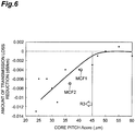
- Fig. 6 is a graph of a relationship between a core pitch Acore and the amount of the transmission loss reduction (dB/km) of the MCF 1 (sample 1) and the MCF 2 (sample 2).
- the amount of the transmission loss reduction (dB/km) is the amount of the transmission loss reduction of each of the MCF 1 and the MCF 2 relative to the transmission loss of the SCF which is the comparative example.
- the SCF can be obtained by drawing a preform having a single core part in which 25 atom ppm of potassium elements have been doped.
- each of the MCF 1 and the MCF 2 can be obtained by drawing a preform in which potassium elements of 25 atom ppm as an average concentration have been doped in two core parts.
- the transmission loss can be more reduced than the SCF when the core pitch ⁇ core is 45 ⁇ m or less.
- the core pitch ⁇ core be 40 ⁇ m or less, and more preferably, 35 ⁇ m or less. In this way, it is preferable that the core pitch ⁇ core be smaller.
- the core pitch ⁇ core indicates a preferable range of the core pitch ⁇ core that can sufficiently reduce the transmission loss.
- a substance having an atomic number equal to or less than that of potassium (K) is used as the alkali metal
- a diffusion coefficient is larger than that of K. Therefore, if the core pitch ⁇ core is still 45 ⁇ m or less, the alkali metal during drawing can be mutually diffused between the cores.
- alkali metal having an atomic number larger than that of potassium since the diffusion speed becomes slow, it is desirable that the core pitch ⁇ core be further smaller.
- it is necessary to design a refractive index profile structure of the core so that the sum h_total of the power coupling coefficients between the cores becomes 2.3 ⁇ 10 -4 /km or less.
- the inter-core XT be - 30 dB or less to maintain a signal quality.
- the transmission loss can be efficiently reduced.
- the effective XT becomes lower. Therefore, an allowable value of the XT value between the adjacent cores can be relaxed.
- the inter-core XT of substantially - 30 dB or less from the reflectance of 4% (about - 14 dB) of air and glass, it is preferable that the inter-core XT be - 16 dB/km in the wavelength used in the system and in the transmission distance, and the core pitch can be relaxed.
- the MCF 2 has an inter-core XT of 16.5 dB which is a relatively large inter-core XT after the propagation of 100 km at the wavelength of 1550 nm.
- inter-core XT 16.5 dB which is a relatively large inter-core XT after the propagation of 100 km at the wavelength of 1550 nm.
- error free transmission becomes available.
- the alkali metal which has been doped in the cores adjacent to each other during drawing diffuses to the outside of the core. Therefore, the transmission loss in the common cladding part can be efficiently reduced.
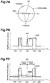
- Figs. 7A to 7C are diagrams of a sectional structure, a refractive index profile, and an alkali metal concentration distribution of a MCF 200B and a preform 100B according to a second embodiment.
- the structure is similar to that of the first embodiment ( Figs. 1A to 1C ), except for a point that an alkali metal doped region 500 is provided in a cladding part 120 between core parts 110 in addition to the two core parts 110.
- the preform 100B includes the core parts 110 respectively extending along a central axis AX and a cladding part 120 for covering each of the core parts 110.
- the MCF 200B according to the present embodiment is obtained by drawing the preform 100B, and a sectional structure thereof is similar to that of the preform 100B.
- a core 210 of the MCF 200B corresponds to the core part 110 of the preform 100B, and a cladding 220 of the MCF 200B corresponds to the cladding part 120 of the preform 100A.
- Fig. 7B is a diagram of a refractive index profile 150B and an alkali metal concentration distribution 160B of the preform 100B along a line L in Fig. 7A .
- the alkali metal doped region 500 in which the alkali metal is doped is formed in the cladding part 120 of the preform 100B.
- the alkali metal concentration distribution is not illustrated in one of the core parts 110.
- the alkali metal doped regions may be formed in all the core parts 110 in the present embodiment.
- Fig. 7C is a diagram of a refractive index profile 250B and an alkali metal concentration distribution 260B of the MCF 200B according to the present embodiment obtained by drawing the preform 100B, and similarly to Fig. 7B, Fig. 7C is a profile along the line L in Fig. 7A .
- ⁇ core-cladding illustrated in Fig. 7C is a distance between a diffusion center position of the alkali metal doped region 500 provided in the cladding part 120 of the preform 100B and the center position of each core 210 of the MCF 200B after drawing.
- the alkali metal by adding the alkali metal to the cladding part 120 in addition to the core part 110 of the preform 100B, a transmission loss can be more efficiently reduced.
- the alkali metal does not diffuse into the core during drawing, and an effect of reduction in the transmission loss cannot be obtained.
- the distance ⁇ core-cladding between the center of the core 210 and the diffusion center position corresponding to the center of the alkali metal doped region 500 in the MCF 200B after drawing is required to be 45 ⁇ m or less. More preferably, the distance ⁇ core-cladding is 40 ⁇ m or less, and more preferably 35 ⁇ m or less.
- the alkali metal when the alkali metal is doped in the core part 110 of the preform 100B, crystals are likely to be generated in the core during drawing, and the transmission loss may be increased due to mixture of impurities other than the alkali metal into the core part 110 in a process for adding the alkali metal to the core part 110. Therefore, by diffusing the alkali metal (alkali metal doped region 500) doped in the cladding part 120 in the drawing process to the core during drawing without directly adding the alkali metal to the core part 110 in the preform stage, a low transmission loss can be obtained without an excessive loss caused by crystallization and the mixture of the impurities, and reduction in a production yield.
- the alkali metal doped regions in the core part 110 and the cladding part 120 in the preform 100B are provided in both core parts 110 and an intermediate region thereof and are extended along the longitudinal direction (central axis AX) of the preform.
- the concentration of the alkali metal at the outer periphery of a fiber is increased due to the diffusion during drawing, and the mechanical strength of the obtained MCF 200B is lowered. Therefore, this is not desirable. Therefore, it is preferable that the concentration of the alkali metal on the surface of the cladding 220 of the MCF 200B be one atom ppm or less.
Landscapes
- Physics & Mathematics (AREA)
- General Physics & Mathematics (AREA)
- Optics & Photonics (AREA)
- Chemical & Material Sciences (AREA)
- Dispersion Chemistry (AREA)
- Glass Compositions (AREA)
- Manufacture, Treatment Of Glass Fibers (AREA)
Applications Claiming Priority (2)
| Application Number | Priority Date | Filing Date | Title |
|---|---|---|---|
| JP2015062668 | 2015-03-25 | ||
| PCT/JP2016/057209 WO2016152507A1 (ja) | 2015-03-25 | 2016-03-08 | マルチコア光ファイバ |
Publications (3)
| Publication Number | Publication Date |
|---|---|
| EP3276384A1 true EP3276384A1 (de) | 2018-01-31 |
| EP3276384A4 EP3276384A4 (de) | 2018-04-18 |
| EP3276384B1 EP3276384B1 (de) | 2022-05-11 |
Family
ID=56978372
Family Applications (1)
| Application Number | Title | Priority Date | Filing Date |
|---|---|---|---|
| EP16768410.9A Active EP3276384B1 (de) | 2015-03-25 | 2016-03-08 | Mehradrige glasfaser |
Country Status (6)
| Country | Link |
|---|---|
| US (1) | US10031285B2 (de) |
| EP (1) | EP3276384B1 (de) |
| JP (1) | JPWO2016152507A1 (de) |
| CN (1) | CN107250856B (de) |
| DK (1) | DK3276384T3 (de) |
| WO (1) | WO2016152507A1 (de) |
Cited By (2)
| Publication number | Priority date | Publication date | Assignee | Title |
|---|---|---|---|---|
| WO2024035666A1 (en) * | 2022-08-12 | 2024-02-15 | Corning Incorporated | Uncoupled multicore optical fiber with alkali doped, off-set trench cores |
| EP4220995A4 (de) * | 2020-09-24 | 2024-04-24 | Sumitomo Electric Industries, Ltd. | Mehradrige glasfaser und optisches übertragungssystem |
Families Citing this family (13)
| Publication number | Priority date | Publication date | Assignee | Title |
|---|---|---|---|---|
| JP6859796B2 (ja) * | 2017-03-28 | 2021-04-14 | 住友電気工業株式会社 | 結合型マルチコア光ファイバの製造方法 |
| WO2020171187A1 (ja) * | 2019-02-22 | 2020-08-27 | 住友電気工業株式会社 | モード依存損失測定装置およびモード依存損失測定方法 |
| US12130394B2 (en) | 2019-10-03 | 2024-10-29 | Schlumberger Technology Corporation | Fiber optic interrogation system |
| JP7677153B2 (ja) * | 2019-10-31 | 2025-05-15 | 住友電気工業株式会社 | 光ファイバ |
| US11733449B2 (en) | 2020-08-10 | 2023-08-22 | Corning Incorporated | Ultra-low-loss coupled-core multicore optical fibers |
| WO2022097639A1 (ja) * | 2020-11-04 | 2022-05-12 | 住友電気工業株式会社 | マルチコア光ファイバ |
| US11726257B2 (en) | 2021-03-05 | 2023-08-15 | Corning Incorporated | Multicore optical fiber |
| JPWO2023054620A1 (de) * | 2021-10-01 | 2023-04-06 | ||
| US20240069271A1 (en) * | 2022-08-26 | 2024-02-29 | Corning Incorporated | Uncoupled-core multicore optical fiber with reduced cross talk |
| JP7505664B1 (ja) * | 2023-01-31 | 2024-06-25 | 住友電気工業株式会社 | マルチコア光ファイバ |
| WO2024161793A1 (ja) * | 2023-01-31 | 2024-08-08 | 住友電気工業株式会社 | マルチコア光ファイバ |
| WO2025090294A1 (en) * | 2023-10-23 | 2025-05-01 | Corning Incorporated | Multicore optical fibers suitable for simultaneous data transmission and quantum communication |
| US20250172746A1 (en) * | 2023-11-28 | 2025-05-29 | Corning Incorporated | Uncoupled multicore optical fiber |
Family Cites Families (15)
| Publication number | Priority date | Publication date | Assignee | Title |
|---|---|---|---|---|
| NL7603832A (nl) * | 1976-04-12 | 1977-10-14 | Philips Nv | Glassamenstellingen. |
| US4452508A (en) * | 1977-06-28 | 1984-06-05 | British Telecommunications | Graded index optical fibres |
| US4573762A (en) * | 1983-06-27 | 1986-03-04 | U.S. Philips Corporation | Germanium-free optical fibers having large numerical apertures |
| JPS60138503A (ja) | 1983-12-27 | 1985-07-23 | Sumitomo Electric Ind Ltd | 多心コア光フアイバ−の製造方法 |
| JPH0810283B2 (ja) | 1984-02-23 | 1996-01-31 | 住友電気工業株式会社 | 光伝送用フアイバ |
| JP2011209702A (ja) | 2010-03-10 | 2011-10-20 | Sumitomo Electric Ind Ltd | マルチコア光ファイバ |
| US9120693B2 (en) * | 2010-11-08 | 2015-09-01 | Corning Incorporated | Multi-core optical fiber ribbons and methods for making the same |
| JP5545236B2 (ja) | 2011-02-03 | 2014-07-09 | 住友電気工業株式会社 | 光ファイバ母材製造方法 |
| JP5974488B2 (ja) * | 2011-04-15 | 2016-08-23 | 住友電気工業株式会社 | 光ファイバおよび光ファイバ母材 |
| US9263846B2 (en) * | 2011-10-05 | 2016-02-16 | University Of Central Florida Research Foundation, Inc. | Systems and methods for amplifying space-multiplexed optical signals |
| US9025239B2 (en) * | 2011-12-13 | 2015-05-05 | Ofs Fitel, Llc | Multi-core erbium-doped fiber amplifier |
| JP6136261B2 (ja) * | 2012-01-23 | 2017-05-31 | 住友電気工業株式会社 | 光ファイバ |
| WO2013129234A1 (ja) * | 2012-02-29 | 2013-09-06 | 住友電気工業株式会社 | マルチコア光ファイバ、マルチコア光ファイバケーブル、およびマルチコア光ファイバ伝送システム |
| JP6156359B2 (ja) * | 2012-02-29 | 2017-07-05 | 住友電気工業株式会社 | マルチコア光ファイバ |
| JP6361101B2 (ja) * | 2012-09-04 | 2018-07-25 | 住友電気工業株式会社 | 光ファイバ |
-
2016
- 2016-03-08 WO PCT/JP2016/057209 patent/WO2016152507A1/ja not_active Ceased
- 2016-03-08 DK DK16768410.9T patent/DK3276384T3/da active
- 2016-03-08 CN CN201680011430.0A patent/CN107250856B/zh active Active
- 2016-03-08 JP JP2017508185A patent/JPWO2016152507A1/ja active Pending
- 2016-03-08 EP EP16768410.9A patent/EP3276384B1/de active Active
-
2017
- 2017-08-23 US US15/683,915 patent/US10031285B2/en active Active
Cited By (3)
| Publication number | Priority date | Publication date | Assignee | Title |
|---|---|---|---|---|
| EP4220995A4 (de) * | 2020-09-24 | 2024-04-24 | Sumitomo Electric Industries, Ltd. | Mehradrige glasfaser und optisches übertragungssystem |
| WO2024035666A1 (en) * | 2022-08-12 | 2024-02-15 | Corning Incorporated | Uncoupled multicore optical fiber with alkali doped, off-set trench cores |
| US12535637B2 (en) | 2022-08-12 | 2026-01-27 | Corning Incorporated | Uncoupled multicore optical fiber with alkali doped, off-set trench cores |
Also Published As
| Publication number | Publication date |
|---|---|
| JPWO2016152507A1 (ja) | 2018-01-11 |
| EP3276384A4 (de) | 2018-04-18 |
| US10031285B2 (en) | 2018-07-24 |
| EP3276384B1 (de) | 2022-05-11 |
| US20170351022A1 (en) | 2017-12-07 |
| WO2016152507A1 (ja) | 2016-09-29 |
| DK3276384T3 (da) | 2022-06-13 |
| CN107250856A (zh) | 2017-10-13 |
| CN107250856B (zh) | 2019-12-06 |
Similar Documents
| Publication | Publication Date | Title |
|---|---|---|
| EP3276384B1 (de) | Mehradrige glasfaser | |
| US10422946B2 (en) | Coupled multi-core optical fiber | |
| CN102156323B (zh) | 一种单模光纤 | |
| EP3715923B1 (de) | Singlemode-glasfaser mit ultrageringem verlust und grosser effektiver fläche und herstellungsverfahren dafür | |
| US9297953B2 (en) | Graded refractive index bending-resistant multimode optical fiber | |
| CN106443876B (zh) | 一种低串扰少模光纤 | |
| CN106908897B (zh) | 光学纤维 | |
| US12546933B2 (en) | Multicore optical fiber | |
| CN106291808A (zh) | 一种超低衰减大有效面积单模光纤 | |
| CN104714273A (zh) | 低衰减少模光纤 | |
| US20120321261A1 (en) | Method for producing optical fiber | |
| CN107608023A (zh) | 一种阶跃型超低衰减少模光纤 | |
| EP3754394B1 (de) | Optische faser | |
| CN106997073A (zh) | 一种超低衰减大有效面积单模光纤 | |
| CN104203850B (zh) | 光纤的制造方法 | |
| CN102826750B (zh) | 光纤制造方法 | |
| CN107193082A (zh) | 一种超低衰减单模光纤 | |
| CN106338793A (zh) | 一种少模光纤 | |
| CN105182471A (zh) | 一种单模光纤 | |
| JPWO2024190234A5 (de) | ||
| US20230176277A1 (en) | Large-effective-mode-area low-loss optical fiber with optimized cladding components | |
| WO2025249168A1 (ja) | マルチコア光ファイバおよびマルチコア光ファイバ母材 | |
| CN106772784A (zh) | 一种宽带折射率渐变的多模光纤 | |
| CN106019470A (zh) | 一种超低衰减单模光纤 | |
| JP2015174796A (ja) | 光ファイバの製造方法及び光ファイバ |
Legal Events
| Date | Code | Title | Description |
|---|---|---|---|
| STAA | Information on the status of an ep patent application or granted ep patent |
Free format text: STATUS: THE INTERNATIONAL PUBLICATION HAS BEEN MADE |
|
| PUAI | Public reference made under article 153(3) epc to a published international application that has entered the european phase |
Free format text: ORIGINAL CODE: 0009012 |
|
| STAA | Information on the status of an ep patent application or granted ep patent |
Free format text: STATUS: REQUEST FOR EXAMINATION WAS MADE |
|
| 17P | Request for examination filed |
Effective date: 20170824 |
|
| AK | Designated contracting states |
Kind code of ref document: A1 Designated state(s): AL AT BE BG CH CY CZ DE DK EE ES FI FR GB GR HR HU IE IS IT LI LT LU LV MC MK MT NL NO PL PT RO RS SE SI SK SM TR |
|
| AX | Request for extension of the european patent |
Extension state: BA ME |
|
| A4 | Supplementary search report drawn up and despatched |
Effective date: 20180315 |
|
| RIC1 | Information provided on ipc code assigned before grant |
Ipc: G02B 6/02 20060101AFI20180309BHEP |
|
| DAV | Request for validation of the european patent (deleted) | ||
| DAX | Request for extension of the european patent (deleted) | ||
| STAA | Information on the status of an ep patent application or granted ep patent |
Free format text: STATUS: EXAMINATION IS IN PROGRESS |
|
| 17Q | First examination report despatched |
Effective date: 20200824 |
|
| GRAP | Despatch of communication of intention to grant a patent |
Free format text: ORIGINAL CODE: EPIDOSNIGR1 |
|
| STAA | Information on the status of an ep patent application or granted ep patent |
Free format text: STATUS: GRANT OF PATENT IS INTENDED |
|
| INTG | Intention to grant announced |
Effective date: 20220208 |
|
| GRAS | Grant fee paid |
Free format text: ORIGINAL CODE: EPIDOSNIGR3 |
|
| GRAA | (expected) grant |
Free format text: ORIGINAL CODE: 0009210 |
|
| STAA | Information on the status of an ep patent application or granted ep patent |
Free format text: STATUS: THE PATENT HAS BEEN GRANTED |
|
| AK | Designated contracting states |
Kind code of ref document: B1 Designated state(s): AL AT BE BG CH CY CZ DE DK EE ES FI FR GB GR HR HU IE IS IT LI LT LU LV MC MK MT NL NO PL PT RO RS SE SI SK SM TR |
|
| REG | Reference to a national code |
Ref country code: GB Ref legal event code: FG4D |
|
| REG | Reference to a national code |
Ref country code: CH Ref legal event code: EP |
|
| REG | Reference to a national code |
Ref country code: AT Ref legal event code: REF Ref document number: 1491913 Country of ref document: AT Kind code of ref document: T Effective date: 20220515 |
|
| REG | Reference to a national code |
Ref country code: DE Ref legal event code: R096 Ref document number: 602016072045 Country of ref document: DE |
|
| REG | Reference to a national code |
Ref country code: IE Ref legal event code: FG4D |
|
| REG | Reference to a national code |
Ref country code: DK Ref legal event code: T3 Effective date: 20220607 |
|
| REG | Reference to a national code |
Ref country code: NO Ref legal event code: T2 Effective date: 20220511 |
|
| REG | Reference to a national code |
Ref country code: LT Ref legal event code: MG9D |
|
| REG | Reference to a national code |
Ref country code: NL Ref legal event code: MP Effective date: 20220511 |
|
| REG | Reference to a national code |
Ref country code: AT Ref legal event code: MK05 Ref document number: 1491913 Country of ref document: AT Kind code of ref document: T Effective date: 20220511 |
|
| PG25 | Lapsed in a contracting state [announced via postgrant information from national office to epo] |
Ref country code: SE Free format text: LAPSE BECAUSE OF FAILURE TO SUBMIT A TRANSLATION OF THE DESCRIPTION OR TO PAY THE FEE WITHIN THE PRESCRIBED TIME-LIMIT Effective date: 20220511 Ref country code: PT Free format text: LAPSE BECAUSE OF FAILURE TO SUBMIT A TRANSLATION OF THE DESCRIPTION OR TO PAY THE FEE WITHIN THE PRESCRIBED TIME-LIMIT Effective date: 20220912 Ref country code: NL Free format text: LAPSE BECAUSE OF FAILURE TO SUBMIT A TRANSLATION OF THE DESCRIPTION OR TO PAY THE FEE WITHIN THE PRESCRIBED TIME-LIMIT Effective date: 20220511 Ref country code: LT Free format text: LAPSE BECAUSE OF FAILURE TO SUBMIT A TRANSLATION OF THE DESCRIPTION OR TO PAY THE FEE WITHIN THE PRESCRIBED TIME-LIMIT Effective date: 20220511 Ref country code: HR Free format text: LAPSE BECAUSE OF FAILURE TO SUBMIT A TRANSLATION OF THE DESCRIPTION OR TO PAY THE FEE WITHIN THE PRESCRIBED TIME-LIMIT Effective date: 20220511 Ref country code: GR Free format text: LAPSE BECAUSE OF FAILURE TO SUBMIT A TRANSLATION OF THE DESCRIPTION OR TO PAY THE FEE WITHIN THE PRESCRIBED TIME-LIMIT Effective date: 20220812 Ref country code: FI Free format text: LAPSE BECAUSE OF FAILURE TO SUBMIT A TRANSLATION OF THE DESCRIPTION OR TO PAY THE FEE WITHIN THE PRESCRIBED TIME-LIMIT Effective date: 20220511 Ref country code: ES Free format text: LAPSE BECAUSE OF FAILURE TO SUBMIT A TRANSLATION OF THE DESCRIPTION OR TO PAY THE FEE WITHIN THE PRESCRIBED TIME-LIMIT Effective date: 20220511 Ref country code: BG Free format text: LAPSE BECAUSE OF FAILURE TO SUBMIT A TRANSLATION OF THE DESCRIPTION OR TO PAY THE FEE WITHIN THE PRESCRIBED TIME-LIMIT Effective date: 20220811 Ref country code: AT Free format text: LAPSE BECAUSE OF FAILURE TO SUBMIT A TRANSLATION OF THE DESCRIPTION OR TO PAY THE FEE WITHIN THE PRESCRIBED TIME-LIMIT Effective date: 20220511 |
|
| PG25 | Lapsed in a contracting state [announced via postgrant information from national office to epo] |
Ref country code: RS Free format text: LAPSE BECAUSE OF FAILURE TO SUBMIT A TRANSLATION OF THE DESCRIPTION OR TO PAY THE FEE WITHIN THE PRESCRIBED TIME-LIMIT Effective date: 20220511 Ref country code: PL Free format text: LAPSE BECAUSE OF FAILURE TO SUBMIT A TRANSLATION OF THE DESCRIPTION OR TO PAY THE FEE WITHIN THE PRESCRIBED TIME-LIMIT Effective date: 20220511 Ref country code: LV Free format text: LAPSE BECAUSE OF FAILURE TO SUBMIT A TRANSLATION OF THE DESCRIPTION OR TO PAY THE FEE WITHIN THE PRESCRIBED TIME-LIMIT Effective date: 20220511 Ref country code: IS Free format text: LAPSE BECAUSE OF FAILURE TO SUBMIT A TRANSLATION OF THE DESCRIPTION OR TO PAY THE FEE WITHIN THE PRESCRIBED TIME-LIMIT Effective date: 20220911 |
|
| PG25 | Lapsed in a contracting state [announced via postgrant information from national office to epo] |
Ref country code: SM Free format text: LAPSE BECAUSE OF FAILURE TO SUBMIT A TRANSLATION OF THE DESCRIPTION OR TO PAY THE FEE WITHIN THE PRESCRIBED TIME-LIMIT Effective date: 20220511 Ref country code: SK Free format text: LAPSE BECAUSE OF FAILURE TO SUBMIT A TRANSLATION OF THE DESCRIPTION OR TO PAY THE FEE WITHIN THE PRESCRIBED TIME-LIMIT Effective date: 20220511 Ref country code: RO Free format text: LAPSE BECAUSE OF FAILURE TO SUBMIT A TRANSLATION OF THE DESCRIPTION OR TO PAY THE FEE WITHIN THE PRESCRIBED TIME-LIMIT Effective date: 20220511 Ref country code: EE Free format text: LAPSE BECAUSE OF FAILURE TO SUBMIT A TRANSLATION OF THE DESCRIPTION OR TO PAY THE FEE WITHIN THE PRESCRIBED TIME-LIMIT Effective date: 20220511 Ref country code: CZ Free format text: LAPSE BECAUSE OF FAILURE TO SUBMIT A TRANSLATION OF THE DESCRIPTION OR TO PAY THE FEE WITHIN THE PRESCRIBED TIME-LIMIT Effective date: 20220511 |
|
| REG | Reference to a national code |
Ref country code: DE Ref legal event code: R097 Ref document number: 602016072045 Country of ref document: DE |
|
| PLBE | No opposition filed within time limit |
Free format text: ORIGINAL CODE: 0009261 |
|
| STAA | Information on the status of an ep patent application or granted ep patent |
Free format text: STATUS: NO OPPOSITION FILED WITHIN TIME LIMIT |
|
| PG25 | Lapsed in a contracting state [announced via postgrant information from national office to epo] |
Ref country code: AL Free format text: LAPSE BECAUSE OF FAILURE TO SUBMIT A TRANSLATION OF THE DESCRIPTION OR TO PAY THE FEE WITHIN THE PRESCRIBED TIME-LIMIT Effective date: 20220511 |
|
| 26N | No opposition filed |
Effective date: 20230214 |
|
| PG25 | Lapsed in a contracting state [announced via postgrant information from national office to epo] |
Ref country code: SI Free format text: LAPSE BECAUSE OF FAILURE TO SUBMIT A TRANSLATION OF THE DESCRIPTION OR TO PAY THE FEE WITHIN THE PRESCRIBED TIME-LIMIT Effective date: 20220511 |
|
| P01 | Opt-out of the competence of the unified patent court (upc) registered |
Effective date: 20230515 |
|
| PG25 | Lapsed in a contracting state [announced via postgrant information from national office to epo] |
Ref country code: MC Free format text: LAPSE BECAUSE OF FAILURE TO SUBMIT A TRANSLATION OF THE DESCRIPTION OR TO PAY THE FEE WITHIN THE PRESCRIBED TIME-LIMIT Effective date: 20220511 |
|
| REG | Reference to a national code |
Ref country code: CH Ref legal event code: PL |
|
| REG | Reference to a national code |
Ref country code: BE Ref legal event code: MM Effective date: 20230331 |
|
| PG25 | Lapsed in a contracting state [announced via postgrant information from national office to epo] |
Ref country code: LU Free format text: LAPSE BECAUSE OF NON-PAYMENT OF DUE FEES Effective date: 20230308 |
|
| REG | Reference to a national code |
Ref country code: IE Ref legal event code: MM4A |
|
| PG25 | Lapsed in a contracting state [announced via postgrant information from national office to epo] |
Ref country code: LI Free format text: LAPSE BECAUSE OF NON-PAYMENT OF DUE FEES Effective date: 20230331 Ref country code: IT Free format text: LAPSE BECAUSE OF FAILURE TO SUBMIT A TRANSLATION OF THE DESCRIPTION OR TO PAY THE FEE WITHIN THE PRESCRIBED TIME-LIMIT Effective date: 20220511 Ref country code: IE Free format text: LAPSE BECAUSE OF NON-PAYMENT OF DUE FEES Effective date: 20230308 Ref country code: CH Free format text: LAPSE BECAUSE OF NON-PAYMENT OF DUE FEES Effective date: 20230331 |
|
| PG25 | Lapsed in a contracting state [announced via postgrant information from national office to epo] |
Ref country code: BE Free format text: LAPSE BECAUSE OF NON-PAYMENT OF DUE FEES Effective date: 20230331 |
|
| PG25 | Lapsed in a contracting state [announced via postgrant information from national office to epo] |
Ref country code: BG Free format text: LAPSE BECAUSE OF FAILURE TO SUBMIT A TRANSLATION OF THE DESCRIPTION OR TO PAY THE FEE WITHIN THE PRESCRIBED TIME-LIMIT Effective date: 20220511 |
|
| PG25 | Lapsed in a contracting state [announced via postgrant information from national office to epo] |
Ref country code: BG Free format text: LAPSE BECAUSE OF FAILURE TO SUBMIT A TRANSLATION OF THE DESCRIPTION OR TO PAY THE FEE WITHIN THE PRESCRIBED TIME-LIMIT Effective date: 20220511 |
|
| PG25 | Lapsed in a contracting state [announced via postgrant information from national office to epo] |
Ref country code: CY Free format text: LAPSE BECAUSE OF FAILURE TO SUBMIT A TRANSLATION OF THE DESCRIPTION OR TO PAY THE FEE WITHIN THE PRESCRIBED TIME-LIMIT; INVALID AB INITIO Effective date: 20160308 |
|
| PG25 | Lapsed in a contracting state [announced via postgrant information from national office to epo] |
Ref country code: HU Free format text: LAPSE BECAUSE OF FAILURE TO SUBMIT A TRANSLATION OF THE DESCRIPTION OR TO PAY THE FEE WITHIN THE PRESCRIBED TIME-LIMIT; INVALID AB INITIO Effective date: 20160308 |
|
| PG25 | Lapsed in a contracting state [announced via postgrant information from national office to epo] |
Ref country code: TR Free format text: LAPSE BECAUSE OF FAILURE TO SUBMIT A TRANSLATION OF THE DESCRIPTION OR TO PAY THE FEE WITHIN THE PRESCRIBED TIME-LIMIT Effective date: 20220511 |
|
| PGFP | Annual fee paid to national office [announced via postgrant information from national office to epo] |
Ref country code: GB Payment date: 20260202 Year of fee payment: 11 |
|
| PGFP | Annual fee paid to national office [announced via postgrant information from national office to epo] |
Ref country code: DE Payment date: 20260128 Year of fee payment: 11 Ref country code: NO Payment date: 20260310 Year of fee payment: 11 Ref country code: DK Payment date: 20260313 Year of fee payment: 11 |
|
| PGFP | Annual fee paid to national office [announced via postgrant information from national office to epo] |
Ref country code: FR Payment date: 20260209 Year of fee payment: 11 |