EP3276649B1 - Polteil für einen nieder-, mittel- oder hochspannungsschutzschalter und verfahren zur herstellung davon - Google Patents
Polteil für einen nieder-, mittel- oder hochspannungsschutzschalter und verfahren zur herstellung davon Download PDFInfo
- Publication number
- EP3276649B1 EP3276649B1 EP16181397.7A EP16181397A EP3276649B1 EP 3276649 B1 EP3276649 B1 EP 3276649B1 EP 16181397 A EP16181397 A EP 16181397A EP 3276649 B1 EP3276649 B1 EP 3276649B1
- Authority
- EP
- European Patent Office
- Prior art keywords
- compensation layer
- insulating housing
- vacuum interrupter
- moulding
- pole part
- Prior art date
- Legal status (The legal status is an assumption and is not a legal conclusion. Google has not performed a legal analysis and makes no representation as to the accuracy of the status listed.)
- Active
Links
Images
Classifications
-
- H—ELECTRICITY
- H01—ELECTRIC ELEMENTS
- H01H—ELECTRIC SWITCHES; RELAYS; SELECTORS; EMERGENCY PROTECTIVE DEVICES
- H01H33/00—High-tension or heavy-current switches with arc-extinguishing or arc-preventing means
- H01H33/60—Switches wherein the means for extinguishing or preventing the arc do not include separate means for obtaining or increasing flow of arc-extinguishing fluid
- H01H33/66—Vacuum switches
- H01H33/662—Housings or protective screens
- H01H33/66207—Specific housing details, e.g. sealing, soldering or brazing
-
- H—ELECTRICITY
- H01—ELECTRIC ELEMENTS
- H01H—ELECTRIC SWITCHES; RELAYS; SELECTORS; EMERGENCY PROTECTIVE DEVICES
- H01H33/00—High-tension or heavy-current switches with arc-extinguishing or arc-preventing means
- H01H33/60—Switches wherein the means for extinguishing or preventing the arc do not include separate means for obtaining or increasing flow of arc-extinguishing fluid
- H01H33/66—Vacuum switches
- H01H33/662—Housings or protective screens
- H01H33/66207—Specific housing details, e.g. sealing, soldering or brazing
- H01H2033/6623—Details relating to the encasing or the outside layers of the vacuum switch housings
-
- H—ELECTRICITY
- H01—ELECTRIC ELEMENTS
- H01H—ELECTRIC SWITCHES; RELAYS; SELECTORS; EMERGENCY PROTECTIVE DEVICES
- H01H2209/00—Layers
- H01H2209/002—Materials
-
- H—ELECTRICITY
- H01—ELECTRIC ELEMENTS
- H01H—ELECTRIC SWITCHES; RELAYS; SELECTORS; EMERGENCY PROTECTIVE DEVICES
- H01H2209/00—Layers
- H01H2209/012—Layers avoiding too large deformation or stress
-
- H—ELECTRICITY
- H01—ELECTRIC ELEMENTS
- H01H—ELECTRIC SWITCHES; RELAYS; SELECTORS; EMERGENCY PROTECTIVE DEVICES
- H01H33/00—High-tension or heavy-current switches with arc-extinguishing or arc-preventing means
- H01H33/02—Details
- H01H33/42—Driving mechanisms
Definitions
- the invention relates to a pole part for a low-, medium- or high voltage circuit breaker, with an insert in an insulating housing, and method for manufacturing the same, according to the preamble of claim 1 and 7.
- WO00/41199A1 describes that a pre-moulded housing for electrical switching apparatus has incorporated therein a vacuum interrupter surrounded by a silicone rubber sleeve.
- the outer surface of the sleeve and the locating cavity for the interrupter have complementary tapered mating surfaces to enable removable location of the interrupter in the housing under axial tension.
- the insulating housing has a side arm for a conductor. The side arm is coupled to the main housing body by a tapered socket and spigot joint effected by a temperature differential shrink fit of the socket onto the spigot.
- EP2706549A1 decribes a method that involves coating a vacuum switching chamber with a soft protective layer made of soft polyurethane or soft silicone at the outer surfaces.
- the soft protective layer is coated with a lost mold made of polyamide or polybutylene terephthalate, such that a circuit breaker unit is manufactured after the chemical cross-linking of the vacuum switching chamber with soft protective layer and the lost mold.
- the circuit breaker unit is contact fitted with multiple electrical connecting conductors, and an epoxy resin molded into a metal mold.
- US2008/087647A1 describes a circuit-breaker pole insulated by solid material, with an electrically non-conductive and dimensionally stable insulating material housing.
- An interrupter is disposed in the housing.
- the interrupter has a fixed contact and a moving contact, which is located opposite the fixed contact on a drive side and is guided in a longitudinally movable manner.
- the invention is, as defined by claim 1, that the compensation layer consist of a potting material on epoxy basis, with a shore hardness of 12 to 90 shore A.
- this new suggestion is to use a thin layer of a potting material, based on epoxy, with a shore hardness similar or less than the actual warm shrinkage tube.
- the insert is a vacuum interrupter or an embedding device.
- the aforesaid use of such a compensation layer is important, because the vacuum interrupter has a ceramic body, which has importantly different thermal expansion parameters then the insulating epoxy housing.
- the compensation layer is important for the preservation of a high insulation standard.
- the compensation layer extends from the complete internal interface of the insert to the complete interface of an upper connection part integrally, which is finally covered by the aforesaid insulating housing.
- Internal interface means the mechanical coverage interface between the insert and the upper connection part at one side, and the resulting inner surface of the insulating housing in that region at the other side.
- the compensation layer covers the interface of the insert and the interface of an upper connection part at least partly, which is finally covered by the aforesaid insulating housing.
- the invention is, with a look to the aforesaid object of the invention, that the compensation layer consist of a potting material on epoxy or polyurethane basis, with a shore hardness of 12 to 90 shore A, and is moulded on the surface of the insert, before the insert with deposed compensation layer is moulded into an outer insulating material housing.
- the insulating housing, moulded on the with a compensation layer covered insert consist of epoxy material, with a shore hardness bigger than the selected shore hardness of the aforesaid potting material of the compensation layer, wherein the aforesaid hardness relation will be reached at the end of the final moulding step of the insulating housing.
- the compensation layer is moulded in such, that it extends from the complete interface of the insert to the complete interface of an upper connection part integrally, which is finally covered by the aforesaid insulating housing.
- the compensation layer is moulded in such, that it covers the interface of the insert and the interface of an upper connection part at least partly, which is finally covered by the aforesaid insulating housing.
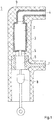
- the figure shows a longitudinal cut of a pole part 1.
- An insert 2 here a vacuum interrupter, I covered with the compensation layer 3, made of potting material on epoxy or polyurethane basis, with a shore hardness of 12 to 90 shore A Polyurethane is an example not covered by the claimed invention.
- the compensation layer extends from the complete surface of the vacuum interrupter 2 up to the upper connection part 4, respectively.
- a movable contact stem 5 is mechanically coupled to a sliding contact system 6, which is electrically connected to the lower connection part 7.
- the movable contact stem is mechanically coupled to a pushrod 8, which is coupled to an external drive.
- the aforesaid thin compensation layer 3 of a potting material based on epoxy or polyurethane material, with a shore hardness similar or less than the actual warm shrinkage tube.
- the insulating housing, moulded on the with a compensation layer covered insert consist of epoxy or polyurethane material, with a shore hardness bigger than the selected shore hardness of the aforesaid potting material of the compensation layer, wherein the aforesaid hardness relation will be reached at the end of the final moulding step of the insulating housing.
Landscapes
- Manufacture Of Switches (AREA)
- Organic Insulating Materials (AREA)
- High-Tension Arc-Extinguishing Switches Without Spraying Means (AREA)
Claims (11)
- Ein Polteil für einen Nieder-, Mittel- oder Hochspannungs-Leistungsschalter, bestehend aus:- einem Isoliergehäuse (9);- einen Einsatz, wobei der Einsatz ein Vakuumunterbrecher (2) ist; und- eine Ausgleichsschicht (3);wobei sich der Vakuumunterbrecher im Isoliergehäuse befindet;
wobei die Kompensationsschicht in Kontakt mit einer Oberfläche der VakuumSchaltröhre steht;
wobei sich die Ausgleichsschicht zwischen der Vakuumschaltröhre und dem Isoliergehäuse befindet; und
wobei die Ausgleichsschicht ein Vergussmaterial auf Epoxidbasis mit einer Shore-Härte von 12 bis 90 Shore A ist. - Polteil nach Anspruch 1, wobei die Ausgleichsschicht an die Vakuumschaltröhre angeformt ist.
- Polteil nach Anspruch 2, wobei das Isoliergehäuse an die Vakuumschaltröhre mit der Ausgleichsschicht angeformt ist oder die Vakuumschaltröhre mit der Ausgleichsschicht in das Isoliergehäuse eingeformt ist.
- Polteil nach einem der Ansprüche 1-3,
wobei das Isoliergehäuse (9) aus einem Epoxid- oder Polyurethanmaterial besteht, dessen Shore-Härte größer ist als die gewählte Shore-Härte des epoxidbasierten Vergussmaterials der Ausgleichsschicht (3). - Polteil nach einem der vorgenannten Ansprüche 1 bis 4,
wobei sich die Ausgleichsschicht (3) über eine komplette Schnittstelle zwischen der Vakuumschaltröhre und einem oberen Anschlussteil (4) erstreckt,und wobei das Isoliergehäuse (9) die Schnittstelle abdeckt. - Polteil nach Anspruch 5,
wobei die Kompensationsschicht eine Innenfläche des oberen Verbindungsteils bedeckt und wobei das obere Verbindungsteil mit der Kompensationsschicht durch das Isoliergehäuse abgedeckt ist. - Nieder-, Mittel- oder Hochspannungsschaltanlage, umfassend ein Polteil nach einem der Ansprüche 1-6.
- Verfahren zur Herstellung eines Polteils für einen Nieder-, Mittel- oder Hochspannungs-Leistungsschalter, umfassend:Abformen einer Kompensationsschicht (3) auf eine Oberfläche einer Vakuumschaltröhre (2); undAnformen eines Isoliergehäuses (9) an die Vakuumschaltröhre mit der Ausgleichsschicht oder Einformen der Vakuumschaltröhre mit der Ausgleichsschicht in das Isoliergehäuse, wobei die Ausgleichsschicht zwischen der Vakuumschaltröhre und dem Isoliergehäuse liegt; undwobei die Ausgleichsschicht ein Vergussmaterial auf Epoxidbasis mit einer Shore-Härte von 12 bis 90 Shore A ist.
- Verfahren nach Anspruch 8, wobei das Isoliergehäuse (9) aus einem Epoxid- oder Polyurethanmaterial besteht, mit einer Shore-Härte, die größer ist als die gewählte Shore-Härte des epoxidbasierten Vergussmaterials der Kompensationsschicht (3), und wobei das Härteverhältnis am Ende des letzten Formungsschritts des Isoliergehäuses erreicht wird.
- Verfahren nach einem der Ansprüche 8-9, wobei das Anformen der Kompensationsschicht (3) so erfolgt, dass sie sich über eine komplette Schnittstelle zwischen der Vakuumschaltröhre und einem oberen Anschlussteil (4) erstreckt,und wobei das Anformen des Isoliergehäuses (9) an die Vakuumschaltröhre mit der Kompensationsschicht oder das Einformen der Vakuumschaltröhre mit der Kompensationsschicht in das Isoliergehäuse so erfolgt, dass das Isoliergehäuse die Schnittstelle abdeckt.
- Verfahren nach Anspruch 10, wobei das Anformen der Kompensationsschicht so erfolgt, dass sie eine Innenfläche des oberen Anschlussteils bedeckt und wobei das Anformen des Isoliergehäuses (9) an die Vakuumschaltröhre mit der Kompensationsschicht oder das Einformen der Vakuumschaltröhre mit der Kompensationsschicht in das Isoliergehäuse so erfolgt, dass das obere Anschlussteil mit der Kompensationsschicht von dem Isoliergehäuse bedeckt wird.
Priority Applications (4)
| Application Number | Priority Date | Filing Date | Title |
|---|---|---|---|
| EP16181397.7A EP3276649B1 (de) | 2016-07-27 | 2016-07-27 | Polteil für einen nieder-, mittel- oder hochspannungsschutzschalter und verfahren zur herstellung davon |
| PCT/EP2017/069028 WO2018019945A1 (en) | 2016-07-27 | 2017-07-27 | Pole part for a low-, medium or high voltage circuit breaker, and method for manufacturing the same |
| CN201780045966.9A CN109478479B (zh) | 2016-07-27 | 2017-07-27 | 用于低压、中压或高压断路器的极部件及其制造方法 |
| US16/255,911 US10770249B2 (en) | 2016-07-27 | 2019-01-24 | Pole part for a low-, medium or high voltage circuit breaker, and method for manufacturing the same |
Applications Claiming Priority (1)
| Application Number | Priority Date | Filing Date | Title |
|---|---|---|---|
| EP16181397.7A EP3276649B1 (de) | 2016-07-27 | 2016-07-27 | Polteil für einen nieder-, mittel- oder hochspannungsschutzschalter und verfahren zur herstellung davon |
Publications (2)
| Publication Number | Publication Date |
|---|---|
| EP3276649A1 EP3276649A1 (de) | 2018-01-31 |
| EP3276649B1 true EP3276649B1 (de) | 2021-05-05 |
Family
ID=56551255
Family Applications (1)
| Application Number | Title | Priority Date | Filing Date |
|---|---|---|---|
| EP16181397.7A Active EP3276649B1 (de) | 2016-07-27 | 2016-07-27 | Polteil für einen nieder-, mittel- oder hochspannungsschutzschalter und verfahren zur herstellung davon |
Country Status (4)
| Country | Link |
|---|---|
| US (1) | US10770249B2 (de) |
| EP (1) | EP3276649B1 (de) |
| CN (1) | CN109478479B (de) |
| WO (1) | WO2018019945A1 (de) |
Families Citing this family (1)
| Publication number | Priority date | Publication date | Assignee | Title |
|---|---|---|---|---|
| EP4439612A1 (de) * | 2023-03-31 | 2024-10-02 | Abb Schweiz Ag | Pfostenteil |
Family Cites Families (13)
| Publication number | Priority date | Publication date | Assignee | Title |
|---|---|---|---|---|
| US5597992A (en) * | 1994-12-09 | 1997-01-28 | Cooper Industries, Inc. | Current interchange for vacuum capacitor switch |
| US6130394A (en) * | 1996-08-26 | 2000-10-10 | Elektrotechnische Weke Fritz Driescher & Sohne GmbH | Hermetically sealed vacuum load interrupter switch with flashover features |
| WO2000041199A1 (en) * | 1999-01-06 | 2000-07-13 | Nu-Lec Industries Pty Ltd | Method for assembly of insulated housings for electrical equipment and incorporation of circuit interrupters therein |
| DE19921477A1 (de) * | 1999-05-08 | 2000-11-09 | Abb T & D Tech Ltd | Freiluftschalterpolteil mit einer Vakuumkammer |
| DE10249615A1 (de) * | 2002-10-21 | 2004-05-13 | Siemens Ag | Herstellung eines feststoffisolierten Schalterpols |
| DE102004047276B4 (de) * | 2004-09-24 | 2006-11-30 | Siemens Ag | Selbsthaftende Elastomerschicht in feststoffisolierten Schalterpolen |
| DE102005039555A1 (de) * | 2005-08-22 | 2007-03-01 | Abb Technology Ltd. | Verfahren zur Herstellung von Schalterpolteilen für Nieder - Mittel - und Hochspannungsschaltanlagen, sowie Schalterpolteil selbst |
| CN101038827A (zh) * | 2006-03-17 | 2007-09-19 | 北海银河高科技产业股份有限公司 | 一种智能化交流真空断路器固封灭弧室极柱 |
| EP2407990A1 (de) * | 2010-07-15 | 2012-01-18 | ABB Technology AG | Polteil eines Schutzschalters und Verfahren zur Herstellung solch eines Polteils |
| US8674254B2 (en) * | 2011-01-31 | 2014-03-18 | Thomas & Betts International, Inc. | Flexible seal for high voltage switch |
| BR112014031107B1 (pt) * | 2012-06-12 | 2021-06-01 | Hubbell Incorporated | Comutador de média ou alta tensão |
| AT513355B1 (de) * | 2012-09-07 | 2021-01-15 | Kuvag Gmbh & Co Kg | Umgossener Leistungsschalter |
| DE102014210587A1 (de) * | 2014-06-04 | 2015-12-17 | Siemens Aktiengesellschaft | Verfahren zur Herstellung eines feststoffisolierten Schalterpols und feststoffisolierter Schalterpol |
-
2016
- 2016-07-27 EP EP16181397.7A patent/EP3276649B1/de active Active
-
2017
- 2017-07-27 WO PCT/EP2017/069028 patent/WO2018019945A1/en not_active Ceased
- 2017-07-27 CN CN201780045966.9A patent/CN109478479B/zh active Active
-
2019
- 2019-01-24 US US16/255,911 patent/US10770249B2/en active Active
Also Published As
| Publication number | Publication date |
|---|---|
| US10770249B2 (en) | 2020-09-08 |
| US20190157029A1 (en) | 2019-05-23 |
| EP3276649A1 (de) | 2018-01-31 |
| CN109478479B (zh) | 2021-01-22 |
| WO2018019945A1 (en) | 2018-02-01 |
| CN109478479A (zh) | 2019-03-15 |
Similar Documents
| Publication | Publication Date | Title |
|---|---|---|
| US8785802B2 (en) | Circuit-breaker pole part and method for producing such a pole part | |
| EP2593953B1 (de) | Verfahren zur herstellung eines polteils für einen schutzschalter | |
| CN101268536B (zh) | 用于低、中、高压开关设备的开关电极部件的制造方法以及开关电极部件本身 | |
| CN106463300B (zh) | 用于制造固体绝缘的开关极的方法以及固体绝缘的开关极 | |
| CA1066332A (en) | Encapsulated vacuum fuse assembly | |
| EP2859567B1 (de) | Mittel- oder hochspannungsschalterbuchse | |
| CN101027740B (zh) | 固体绝缘的开关极中的自粘附式弹性体层 | |
| US20060011589A1 (en) | Production of a circuit-breaker pole, insulated by a solid material | |
| US6828521B2 (en) | Method for increasing insulation level in an encapsulation | |
| CN109791858B (zh) | 高压开关装置和带有高压开关装置的开关设备以及高压开关装置的制造方法 | |
| US2958844A (en) | High voltage, high altitude bushing | |
| WO2013113499A1 (en) | Vacuum interrupter with transition areas between metal housing parts and ceramic housing parts covered by insulating material | |
| NO319578B1 (no) | Fremgangsmate til fremstilling av en isolator | |
| US10770249B2 (en) | Pole part for a low-, medium or high voltage circuit breaker, and method for manufacturing the same | |
| US9004929B2 (en) | Manufacturing method for electric component and electrical component | |
| JP3833444B2 (ja) | モールド真空バルブ及びその製造方法 | |
| CN109844893B (zh) | 高压开关装置和带有高压开关装置的开关设备以及高压开关装置的制造方法 | |
| RU2574337C2 (ru) | Полюсная часть автоматического выключателя и способ ее изготовления | |
| CA3216950A1 (en) | Insulator with external surface configured to reduce electrical stress concentrations | |
| JP4939924B2 (ja) | 電気機器の接続装置 |
Legal Events
| Date | Code | Title | Description |
|---|---|---|---|
| PUAI | Public reference made under article 153(3) epc to a published international application that has entered the european phase |
Free format text: ORIGINAL CODE: 0009012 |
|
| STAA | Information on the status of an ep patent application or granted ep patent |
Free format text: STATUS: THE APPLICATION HAS BEEN PUBLISHED |
|
| AK | Designated contracting states |
Kind code of ref document: A1 Designated state(s): AL AT BE BG CH CY CZ DE DK EE ES FI FR GB GR HR HU IE IS IT LI LT LU LV MC MK MT NL NO PL PT RO RS SE SI SK SM TR |
|
| AX | Request for extension of the european patent |
Extension state: BA ME |
|
| STAA | Information on the status of an ep patent application or granted ep patent |
Free format text: STATUS: REQUEST FOR EXAMINATION WAS MADE |
|
| 17P | Request for examination filed |
Effective date: 20180629 |
|
| RBV | Designated contracting states (corrected) |
Designated state(s): AL AT BE BG CH CY CZ DE DK EE ES FI FR GB GR HR HU IE IS IT LI LT LU LV MC MK MT NL NO PL PT RO RS SE SI SK SM TR |
|
| STAA | Information on the status of an ep patent application or granted ep patent |
Free format text: STATUS: EXAMINATION IS IN PROGRESS |
|
| 17Q | First examination report despatched |
Effective date: 20190814 |
|
| GRAJ | Information related to disapproval of communication of intention to grant by the applicant or resumption of examination proceedings by the epo deleted |
Free format text: ORIGINAL CODE: EPIDOSDIGR1 |
|
| GRAP | Despatch of communication of intention to grant a patent |
Free format text: ORIGINAL CODE: EPIDOSNIGR1 |
|
| RIC1 | Information provided on ipc code assigned before grant |
Ipc: H01H 33/662 20060101AFI20201016BHEP Ipc: B29C 45/16 20060101ALN20201016BHEP |
|
| GRAP | Despatch of communication of intention to grant a patent |
Free format text: ORIGINAL CODE: EPIDOSNIGR1 |
|
| STAA | Information on the status of an ep patent application or granted ep patent |
Free format text: STATUS: GRANT OF PATENT IS INTENDED |
|
| RIC1 | Information provided on ipc code assigned before grant |
Ipc: B29C 45/16 20060101ALN20201105BHEP Ipc: H01H 33/662 20060101AFI20201105BHEP |
|
| RIC1 | Information provided on ipc code assigned before grant |
Ipc: H01H 33/662 20060101AFI20201111BHEP Ipc: B29C 45/16 20060101ALN20201111BHEP |
|
| INTG | Intention to grant announced |
Effective date: 20201207 |
|
| GRAS | Grant fee paid |
Free format text: ORIGINAL CODE: EPIDOSNIGR3 |
|
| GRAA | (expected) grant |
Free format text: ORIGINAL CODE: 0009210 |
|
| STAA | Information on the status of an ep patent application or granted ep patent |
Free format text: STATUS: THE PATENT HAS BEEN GRANTED |
|
| RAP3 | Party data changed (applicant data changed or rights of an application transferred) |
Owner name: ABB SCHWEIZ AG |
|
| AK | Designated contracting states |
Kind code of ref document: B1 Designated state(s): AL AT BE BG CH CY CZ DE DK EE ES FI FR GB GR HR HU IE IS IT LI LT LU LV MC MK MT NL NO PL PT RO RS SE SI SK SM TR |
|
| REG | Reference to a national code |
Ref country code: GB Ref legal event code: FG4D |
|
| REG | Reference to a national code |
Ref country code: CH Ref legal event code: EP |
|
| REG | Reference to a national code |
Ref country code: AT Ref legal event code: REF Ref document number: 1390856 Country of ref document: AT Kind code of ref document: T Effective date: 20210515 |
|
| REG | Reference to a national code |
Ref country code: DE Ref legal event code: R096 Ref document number: 602016057255 Country of ref document: DE |
|
| REG | Reference to a national code |
Ref country code: IE Ref legal event code: FG4D |
|
| REG | Reference to a national code |
Ref country code: LT Ref legal event code: MG9D |
|
| REG | Reference to a national code |
Ref country code: AT Ref legal event code: MK05 Ref document number: 1390856 Country of ref document: AT Kind code of ref document: T Effective date: 20210505 |
|
| PG25 | Lapsed in a contracting state [announced via postgrant information from national office to epo] |
Ref country code: BG Free format text: LAPSE BECAUSE OF FAILURE TO SUBMIT A TRANSLATION OF THE DESCRIPTION OR TO PAY THE FEE WITHIN THE PRESCRIBED TIME-LIMIT Effective date: 20210805 Ref country code: AT Free format text: LAPSE BECAUSE OF FAILURE TO SUBMIT A TRANSLATION OF THE DESCRIPTION OR TO PAY THE FEE WITHIN THE PRESCRIBED TIME-LIMIT Effective date: 20210505 Ref country code: HR Free format text: LAPSE BECAUSE OF FAILURE TO SUBMIT A TRANSLATION OF THE DESCRIPTION OR TO PAY THE FEE WITHIN THE PRESCRIBED TIME-LIMIT Effective date: 20210505 Ref country code: LT Free format text: LAPSE BECAUSE OF FAILURE TO SUBMIT A TRANSLATION OF THE DESCRIPTION OR TO PAY THE FEE WITHIN THE PRESCRIBED TIME-LIMIT Effective date: 20210505 Ref country code: FI Free format text: LAPSE BECAUSE OF FAILURE TO SUBMIT A TRANSLATION OF THE DESCRIPTION OR TO PAY THE FEE WITHIN THE PRESCRIBED TIME-LIMIT Effective date: 20210505 |
|
| PG25 | Lapsed in a contracting state [announced via postgrant information from national office to epo] |
Ref country code: PL Free format text: LAPSE BECAUSE OF FAILURE TO SUBMIT A TRANSLATION OF THE DESCRIPTION OR TO PAY THE FEE WITHIN THE PRESCRIBED TIME-LIMIT Effective date: 20210505 Ref country code: NO Free format text: LAPSE BECAUSE OF FAILURE TO SUBMIT A TRANSLATION OF THE DESCRIPTION OR TO PAY THE FEE WITHIN THE PRESCRIBED TIME-LIMIT Effective date: 20210805 Ref country code: PT Free format text: LAPSE BECAUSE OF FAILURE TO SUBMIT A TRANSLATION OF THE DESCRIPTION OR TO PAY THE FEE WITHIN THE PRESCRIBED TIME-LIMIT Effective date: 20210906 Ref country code: RS Free format text: LAPSE BECAUSE OF FAILURE TO SUBMIT A TRANSLATION OF THE DESCRIPTION OR TO PAY THE FEE WITHIN THE PRESCRIBED TIME-LIMIT Effective date: 20210505 Ref country code: SE Free format text: LAPSE BECAUSE OF FAILURE TO SUBMIT A TRANSLATION OF THE DESCRIPTION OR TO PAY THE FEE WITHIN THE PRESCRIBED TIME-LIMIT Effective date: 20210505 Ref country code: GR Free format text: LAPSE BECAUSE OF FAILURE TO SUBMIT A TRANSLATION OF THE DESCRIPTION OR TO PAY THE FEE WITHIN THE PRESCRIBED TIME-LIMIT Effective date: 20210806 Ref country code: LV Free format text: LAPSE BECAUSE OF FAILURE TO SUBMIT A TRANSLATION OF THE DESCRIPTION OR TO PAY THE FEE WITHIN THE PRESCRIBED TIME-LIMIT Effective date: 20210505 Ref country code: IS Free format text: LAPSE BECAUSE OF FAILURE TO SUBMIT A TRANSLATION OF THE DESCRIPTION OR TO PAY THE FEE WITHIN THE PRESCRIBED TIME-LIMIT Effective date: 20210905 |
|
| REG | Reference to a national code |
Ref country code: NL Ref legal event code: MP Effective date: 20210505 |
|
| PG25 | Lapsed in a contracting state [announced via postgrant information from national office to epo] |
Ref country code: NL Free format text: LAPSE BECAUSE OF FAILURE TO SUBMIT A TRANSLATION OF THE DESCRIPTION OR TO PAY THE FEE WITHIN THE PRESCRIBED TIME-LIMIT Effective date: 20210505 |
|
| PG25 | Lapsed in a contracting state [announced via postgrant information from national office to epo] |
Ref country code: SK Free format text: LAPSE BECAUSE OF FAILURE TO SUBMIT A TRANSLATION OF THE DESCRIPTION OR TO PAY THE FEE WITHIN THE PRESCRIBED TIME-LIMIT Effective date: 20210505 Ref country code: SM Free format text: LAPSE BECAUSE OF FAILURE TO SUBMIT A TRANSLATION OF THE DESCRIPTION OR TO PAY THE FEE WITHIN THE PRESCRIBED TIME-LIMIT Effective date: 20210505 Ref country code: CZ Free format text: LAPSE BECAUSE OF FAILURE TO SUBMIT A TRANSLATION OF THE DESCRIPTION OR TO PAY THE FEE WITHIN THE PRESCRIBED TIME-LIMIT Effective date: 20210505 Ref country code: DK Free format text: LAPSE BECAUSE OF FAILURE TO SUBMIT A TRANSLATION OF THE DESCRIPTION OR TO PAY THE FEE WITHIN THE PRESCRIBED TIME-LIMIT Effective date: 20210505 Ref country code: EE Free format text: LAPSE BECAUSE OF FAILURE TO SUBMIT A TRANSLATION OF THE DESCRIPTION OR TO PAY THE FEE WITHIN THE PRESCRIBED TIME-LIMIT Effective date: 20210505 Ref country code: RO Free format text: LAPSE BECAUSE OF FAILURE TO SUBMIT A TRANSLATION OF THE DESCRIPTION OR TO PAY THE FEE WITHIN THE PRESCRIBED TIME-LIMIT Effective date: 20210505 Ref country code: ES Free format text: LAPSE BECAUSE OF FAILURE TO SUBMIT A TRANSLATION OF THE DESCRIPTION OR TO PAY THE FEE WITHIN THE PRESCRIBED TIME-LIMIT Effective date: 20210505 |
|
| REG | Reference to a national code |
Ref country code: DE Ref legal event code: R097 Ref document number: 602016057255 Country of ref document: DE |
|
| REG | Reference to a national code |
Ref country code: CH Ref legal event code: PL |
|
| PLBE | No opposition filed within time limit |
Free format text: ORIGINAL CODE: 0009261 |
|
| STAA | Information on the status of an ep patent application or granted ep patent |
Free format text: STATUS: NO OPPOSITION FILED WITHIN TIME LIMIT |
|
| PG25 | Lapsed in a contracting state [announced via postgrant information from national office to epo] |
Ref country code: MC Free format text: LAPSE BECAUSE OF FAILURE TO SUBMIT A TRANSLATION OF THE DESCRIPTION OR TO PAY THE FEE WITHIN THE PRESCRIBED TIME-LIMIT Effective date: 20210505 |
|
| REG | Reference to a national code |
Ref country code: BE Ref legal event code: MM Effective date: 20210731 |
|
| 26N | No opposition filed |
Effective date: 20220208 |
|
| GBPC | Gb: european patent ceased through non-payment of renewal fee |
Effective date: 20210805 |
|
| PG25 | Lapsed in a contracting state [announced via postgrant information from national office to epo] |
Ref country code: LI Free format text: LAPSE BECAUSE OF NON-PAYMENT OF DUE FEES Effective date: 20210731 Ref country code: CH Free format text: LAPSE BECAUSE OF NON-PAYMENT OF DUE FEES Effective date: 20210731 |
|
| PG25 | Lapsed in a contracting state [announced via postgrant information from national office to epo] |
Ref country code: IS Free format text: LAPSE BECAUSE OF FAILURE TO SUBMIT A TRANSLATION OF THE DESCRIPTION OR TO PAY THE FEE WITHIN THE PRESCRIBED TIME-LIMIT Effective date: 20210905 Ref country code: LU Free format text: LAPSE BECAUSE OF NON-PAYMENT OF DUE FEES Effective date: 20210727 Ref country code: AL Free format text: LAPSE BECAUSE OF FAILURE TO SUBMIT A TRANSLATION OF THE DESCRIPTION OR TO PAY THE FEE WITHIN THE PRESCRIBED TIME-LIMIT Effective date: 20210505 |
|
| PG25 | Lapsed in a contracting state [announced via postgrant information from national office to epo] |
Ref country code: IT Free format text: LAPSE BECAUSE OF FAILURE TO SUBMIT A TRANSLATION OF THE DESCRIPTION OR TO PAY THE FEE WITHIN THE PRESCRIBED TIME-LIMIT Effective date: 20210505 Ref country code: IE Free format text: LAPSE BECAUSE OF NON-PAYMENT OF DUE FEES Effective date: 20210727 Ref country code: GB Free format text: LAPSE BECAUSE OF NON-PAYMENT OF DUE FEES Effective date: 20210805 Ref country code: BE Free format text: LAPSE BECAUSE OF NON-PAYMENT OF DUE FEES Effective date: 20210731 |
|
| PG25 | Lapsed in a contracting state [announced via postgrant information from national office to epo] |
Ref country code: HU Free format text: LAPSE BECAUSE OF FAILURE TO SUBMIT A TRANSLATION OF THE DESCRIPTION OR TO PAY THE FEE WITHIN THE PRESCRIBED TIME-LIMIT; INVALID AB INITIO Effective date: 20160727 |
|
| PG25 | Lapsed in a contracting state [announced via postgrant information from national office to epo] |
Ref country code: CY Free format text: LAPSE BECAUSE OF FAILURE TO SUBMIT A TRANSLATION OF THE DESCRIPTION OR TO PAY THE FEE WITHIN THE PRESCRIBED TIME-LIMIT Effective date: 20210505 |
|
| PG25 | Lapsed in a contracting state [announced via postgrant information from national office to epo] |
Ref country code: MK Free format text: LAPSE BECAUSE OF FAILURE TO SUBMIT A TRANSLATION OF THE DESCRIPTION OR TO PAY THE FEE WITHIN THE PRESCRIBED TIME-LIMIT Effective date: 20210505 |
|
| PG25 | Lapsed in a contracting state [announced via postgrant information from national office to epo] |
Ref country code: TR Free format text: LAPSE BECAUSE OF FAILURE TO SUBMIT A TRANSLATION OF THE DESCRIPTION OR TO PAY THE FEE WITHIN THE PRESCRIBED TIME-LIMIT Effective date: 20210505 |
|
| PG25 | Lapsed in a contracting state [announced via postgrant information from national office to epo] |
Ref country code: MT Free format text: LAPSE BECAUSE OF FAILURE TO SUBMIT A TRANSLATION OF THE DESCRIPTION OR TO PAY THE FEE WITHIN THE PRESCRIBED TIME-LIMIT Effective date: 20210505 |
|
| PGFP | Annual fee paid to national office [announced via postgrant information from national office to epo] |
Ref country code: DE Payment date: 20240719 Year of fee payment: 9 |
|
| PGFP | Annual fee paid to national office [announced via postgrant information from national office to epo] |
Ref country code: FR Payment date: 20240730 Year of fee payment: 9 |
|
| REG | Reference to a national code |
Ref country code: DE Ref legal event code: R119 Ref document number: 602016057255 Country of ref document: DE |
|
| PG25 | Lapsed in a contracting state [announced via postgrant information from national office to epo] |
Ref country code: DE Free format text: LAPSE BECAUSE OF NON-PAYMENT OF DUE FEES Effective date: 20260203 |
|
| PG25 | Lapsed in a contracting state [announced via postgrant information from national office to epo] |
Ref country code: FR Free format text: LAPSE BECAUSE OF NON-PAYMENT OF DUE FEES Effective date: 20250731 |