EP3276779B1 - Agencement de chargement pour accessoires électroniques - Google Patents
Agencement de chargement pour accessoires électroniques Download PDFInfo
- Publication number
- EP3276779B1 EP3276779B1 EP17190546.6A EP17190546A EP3276779B1 EP 3276779 B1 EP3276779 B1 EP 3276779B1 EP 17190546 A EP17190546 A EP 17190546A EP 3276779 B1 EP3276779 B1 EP 3276779B1
- Authority
- EP
- European Patent Office
- Prior art keywords
- wireless headset
- docking station
- pins
- power
- electronic system
- Prior art date
- Legal status (The legal status is an assumption and is not a legal conclusion. Google has not performed a legal analysis and makes no representation as to the accuracy of the status listed.)
- Active
Links
Images




Classifications
-
- H—ELECTRICITY
- H04—ELECTRIC COMMUNICATION TECHNIQUE
- H04M—TELEPHONIC COMMUNICATION
- H04M1/00—Substation equipment, e.g. for use by subscribers
- H04M1/02—Constructional features of telephone sets
- H04M1/0202—Portable telephone sets, e.g. cordless phones, mobile phones or bar type handsets
- H04M1/0254—Portable telephone sets, e.g. cordless phones, mobile phones or bar type handsets comprising one or a plurality of mechanically detachable modules
- H04M1/0258—Portable telephone sets, e.g. cordless phones, mobile phones or bar type handsets comprising one or a plurality of mechanically detachable modules for a headset device
-
- H—ELECTRICITY
- H02—GENERATION; CONVERSION OR DISTRIBUTION OF ELECTRIC POWER
- H02J—ELECTRIC POWER NETWORKS; CIRCUIT ARRANGEMENTS OR SYSTEMS FOR SUPPLYING OR DISTRIBUTING ELECTRIC POWER; SYSTEMS FOR STORING ELECTRIC ENERGY
- H02J7/00—Circuit arrangements for charging or discharging batteries or for supplying loads from batteries
- H02J7/34—Parallel operation in networks using both storage and other DC sources, e.g. providing buffering
- H02J7/342—The other DC source being a battery actively interacting with the first one, i.e. battery to battery charging
-
- H—ELECTRICITY
- H04—ELECTRIC COMMUNICATION TECHNIQUE
- H04M—TELEPHONIC COMMUNICATION
- H04M1/00—Substation equipment, e.g. for use by subscribers
- H04M1/02—Constructional features of telephone sets
- H04M1/04—Supports for telephone transmitters or receivers
-
- H—ELECTRICITY
- H04—ELECTRIC COMMUNICATION TECHNIQUE
- H04M—TELEPHONIC COMMUNICATION
- H04M1/00—Substation equipment, e.g. for use by subscribers
- H04M1/02—Constructional features of telephone sets
- H04M1/04—Supports for telephone transmitters or receivers
- H04M1/05—Supports for telephone transmitters or receivers specially adapted for use on head, throat or breast
-
- H—ELECTRICITY
- H04—ELECTRIC COMMUNICATION TECHNIQUE
- H04M—TELEPHONIC COMMUNICATION
- H04M1/00—Substation equipment, e.g. for use by subscribers
- H04M1/60—Substation equipment, e.g. for use by subscribers including speech amplifiers
- H04M1/6033—Substation equipment, e.g. for use by subscribers including speech amplifiers for providing handsfree use or a loudspeaker mode in telephone sets
- H04M1/6041—Portable telephones adapted for handsfree use
- H04M1/6058—Portable telephones adapted for handsfree use involving the use of a headset accessory device connected to the portable telephone
- H04M1/6066—Portable telephones adapted for handsfree use involving the use of a headset accessory device connected to the portable telephone including a wireless connection
Definitions
- Portable electronic devices such as cellular phones may be used with detachable or wireless electronic accessories such as wireless headsets. Such electronic accessories typically need to be charged in order to have sufficient power for normal operation.
- Figs. 1A-C show conventional arrangements for charging wireless headsets.
- Fig. 1A shows an example conventional arrangement in which a headset 112 is charged through a charger 111.
- Charger 111 includes, for example, a connector 114 to be plugged into headset 112, an AC adapter 118 to be plugged into a wall outlet (or an outlet of an extension cable connected to a wall outlet), and a cable 116 connecting connector 114 and AC adapter 118.
- headset 112 it is not possible to charge headset 112 when there is no wall outlet nearby, such as when a user of headset 112 is riding a car, or when the user does not carry charger 111 with him/her. Further, after charging headset 112 at a certain wall outlet, a user of headset 112 is typically required to return to the location of the wall outlet to pick up headset 112 and charger 111. Therefore, much inconvenience, inflexibility, and immobility may be involved in such an arrangement. Still further, AC adapter 118 may be bulky, and cable 116 may be long and prone to tangle. As such, it is typically inconvenient for the user to carry and to handle charger 111, in addition to carrying and handling another charger for a cellular phone with which headset 112 pairs and works.
- Fig. 1B shows another example conventional arrangement in which a headset 122 is charged through a charger 121 and a cradle 120.
- Charger 121 includes, for example, a connector 124 to be plugged into cradle 120, an AC adapter 128 to be plugged into a wall outlet (or an outlet of an extension cable connected to a wall outlet), and a cable 126 connecting connector 124 and AC adapter 128.
- Cradle 120 includes, for example, a port to receive connector 124, conductive contacts to transmit power to headset 122, and appropriate structural components to mechanically support headset 122 while disposed in cradle 120.
- Such an arrangement may provide mechanical support and protection for headset 122 during charging. However, such an arrangement again limits the charging of headset 122 to locations near a wall outlet. Further, cradle 120 represents another bulky component that requires the user to carry and handle if the user wishes to charge headset 122 while away from home.
- Fig. 1C shows still another example conventional arrangement in which headset 132 is charged by a computer 140 through a USB cable 131.
- USB cable 131 includes, for example a USB connector 138 to be plugged into a USB port 142 of computer 140, and a connector 132 to be plugged into headset 132.
- computer 140 When connected with headset 132, computer 140 first establishes a host-client relationship with headset 132 and then transmits power to headset 132.
- a USB host and a USB client are typically required, with computer 140 performing the function of the USB host and headset 132 performing the function of the USB client in the example of Fig. 1C .
- headset 132 cannot be charged when there is no available USB host device such as computer 140 nearby.
- a USB host device such as computer 140 typically needs to be turned on in order to establish a host-client relationship with headset 132, and a headset 132 user may be required to wait a significant amount of time for the USB host device to turn on.
- a user charges headset 132 at a USB host device that is not portable or not carried with the user, the user is typically required to return to the USB host device to pick up headset 132. If no USB host is available, headset 132, which assumes the role of a USB client in receiving charge from another device in the example of Fig. 1C , cannot be charged. Therefore, much inconvenience may be involved in such an arrangement.
- EP 1536 615 A1 relates to a portable electronic device, comprising: a first transceiver for wirelessly transmitting and receiving electromagnetic signals; a headset element comprising a second transceiver for wirelessly transmitting and receiving electromagnetic signals from the first transceiver, a microphone, a battery and a loudspeaker; docking means for docking the headset onto the electronic device, said docking means providing power supply to said battery when the headset element is docked.
- EP 1414 221 A1 discloses a headset carrying device, provided separately from a mobile telephone, and including a headset for wireless communication with the mobile telephone and a charger for recharging the power supply unit of headset.
- GB 2 416 087 A relates to a loudspeaking handsfree in-car holder for a wireless headset of a radiotelephone.
- EP 1 505 801 A discloses a holster for supporting and charging a wireless peripheral of a mobile device.
- EP 1 326 410 A1 discloses a handsfree wireless communication system for handsfree communication between a user and a mobile phone.
- US 2006/147078 A1 discloses a headset capable of receiving signals from an electronic device, a method of manufacturing same, and ear loop and earplug capable of removable engagement with same.
- the invention relates, in an embodiment, to a charging arrangement for an electronic accessory to a portable electronic device.
- the arrangement includes a docking station configured to be coupled with at least one of a power port and a data port of the portable electronic device.
- the docking station includes a first docking station port having first set of docking station pins for electrically coupling with pins of the at least one of the power port and the data port of the portable electronic device.
- the docking station also includes an accessory charging port having recess portion adapted to provide mechanical support to the electronic accessory when the electronic accessory is coupled to the docking station to be charged.
- the docking station further includes a second set of docking station pins configured to electrically couple with pins disposed on the electronic accessory, wherein the electronic accessory is charged by power provided by the portable electronic device through the first set of docking station pins.
- the invention in another embodiment, relates to a charging arrangement for an electronic accessory to a portable electronic device.
- the arrangement includes a plug body having a first end configured to be plugged into a cigarette lighter power port.
- the arrangement further includes a first set of conductors configured to provide power to the portable electronic device for charging the portable electronic device.
- the arrangement also includes an accessory charging port disposed at least partially within the plug body, the accessory charging port being configured to mechanically receive the electronic accessory when the electronic accessory is plugged into the accessory charging port for charging.
- the arrangement additionally includes a first set of charging pins disposed at least partially within the accessory charging port for providing power to the electronic accessory when the electronic accessory is plugged into the accessory charging port for charging
- the invention in another embodiment, relates to a cellular phone system that includes a cellular phone having a first speaker, a first microphone, and cellular phone battery.
- the cellular phone system also includes a detachable headset comprising at least a second speaker, a second microphone, and a headset battery.
- the cellular phone system further includes a detachable docking station configured to be coupled with at least one of a power port and a data port of the cellular phone.
- the docking station includes a first docking station port having first set of docking station pins for electrically coupling with pins of the at least one of the power port and the data port of the cellular phone.
- the docking station also includes an accessory charging port having recess portion adapted to provide mechanical support to the headset when the headset is coupled to the docking station to be charged.
- the docking station further includes a second set of docking station pins configured to electrically couple with pins disposed on the headset, wherein the headset is charged by power provided by the cellular phone through the first set of docking station pins, wherein the docking station is configured to be detachably coupled with the cellular phone and wherein the detachable headset is configured to be detachably coupled with the docking station.
- An embodiment includes a docking station (or an intermediary device) that connects an electronic accessory and a portable electronic device such that the electronic accessory may receive power from the portable electronic device through the docking station.
- the docking station includes electronic circuitry configured to condition and to control the power received by the portable electronic accessory.
- the docking station includes a recess portion configured to provide mechanical support for and storage of the electronic accessory.
- the electronic accessory is protected from potential damage and is located with the electronic device for convenient use.
- Another embodiment includes a charger configured to connect both the electronic accessory and the portable electronic device to a power source. Accordingly, the charger is capable of simultaneously charging both of the electronic accessory and the electronic device.
- the charging power comes from a cigarette lighter power port of an automobile.
- the charger includes a recess portion configure to provide mechanical support and storage of the electronic accessory.
- the electronic accessory is a wireless headset
- the portable electronic device represents a portable communication device such as a cellular phone.
- Fig. 2 shows, in accordance with one or more embodiments of the present invention, a charging arrangement for charging a wireless headset 220.
- Wireless headset 220 represents an electronic accessory usually used in conjunction with a portable electronic device, which is represented by a cellular phone 200.
- Wireless headset 220 includes one or more transducers for conversion between audible sounds and electrical signals.
- wireless headset may include a microphone and/or an earphone.
- the charging arrangement includes a docking station 210.
- Docking station 210 is configured to be coupled with cellular phone 200.
- docking station 210 is configured to conform to the form factor or the shape of an end of cellular phone 200.
- docking station 210 is configured to be attached to one end of cellular phone 200.
- docking station 210 includes a docking station port (not seen in the perspective angle of Fig. 2 ) configured to electrically couple with interface 202 of cellular phone 200.
- docking station 210 may include a short cable configured to be coupled with interface 202 as well as a latching mechanism for removably securing docking station 210 onto cellular phone 200. Through interface 202, docking station may receive power from the battery and/or a charging circuit of cellular phone 200.
- docking station 210 includes a recess portion 218 adapted to capture and mechanically support at least a portion of wireless headset 220.
- Recess portion 218 may provide protection and convenient storage for wireless headset 220, thereby solving prior art storage and protection problems involving using wireless headsets.
- wireless headsets are typically disposed in ways that may expose them to risks of loss or damage, given typical delicacy and fragility of the wireless headsets.
- headset users may wear wireless headsets on their ears, hang wireless headsets on their chests using lanyards, or dispose wireless headsets in their pockets or purses.
- the wireless headsets may be prone to drop from the ears or pockets or to collide with hard objects such as, for example, a desk in front of a user's chest or keys in a user's purse.
- wearing the wireless headset during face-to-face conversations may be considered improper manner.
- storing wireless headset 220 using recess portion 218, a user may avoid the storage and protection problems.
- docking station 210 includes pins 213 (i.e., conductive contacts) configured to electrically couple with pins 223 disposed on wireless headset 220.
- pins 213 i.e., conductive contacts
- docking station 210 may receive power from cellular phone 200 and transmit the power, through pins 213 and 223, to wireless headset 220, thereby charging wireless headset 220.
- the power coupling between docking station 210 and headset 220 may be accomplished using a charging approach that does not involve actual mechanical contact of electrically conductive pins, e.g., via magnetic coupling.
- a pairing relationship between cellular phone 200 and wireless headset 220 is automatically established without a manual configuration process.
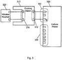
- Fig. 3 shows, in accordance with one or more embodiments of the present invention, a simplified block diagram of a charging arrangement for charging a wireless headset 320 with power from a cellular phone 300.
- Cellular phone 300 includes a power port 302 and a data port 304, wherein power port 302 is used in the charging arrangement.
- the charging arrangement includes a docking station 310.
- Docking station 310 includes docking station port 312, which includes pins (or conductive contacts) configured to electrically couple with pins of power port 302, for receiving power from cellular phone 300.
- power ports of cellular phones only receive input, but do not provide output.
- power port 302 is adapted to provide output from the battery of cellular phone 300 or from the charging circuitry in cellular phone 300.
- docking station 310 further includes electronic circuitry configured to cause cellular phone 300 to enter a state (e.g., by sending a signal via a data pin of data port 304 or a power pin of power port 302) whereby power from a battery in cellular phone 300 is present on at least one pin of power port 302.
- Docking station 310 further includes an accessory charging port 316, which includes pins configured to electrically couple with pins disposed on wireless headset 320, for transmitting power from cellular phone 300 to wireless headset 320. As such, wireless headset 320 may be charged with power from cellular phone 300 through docking station 310.
- Fig. 4 shows, in accordance with one or more embodiments of the present invention, a block diagram of a charging arrangement for charging a wireless headset 420 with power from a cellular phone 400.
- Cellular phone 400 includes a power port 402 and a data port 404, wherein data port 404 is used in the charging arrangement.
- the charging arrangement includes a docking station 410.
- Docking station 410 includes a first set of docking station pins 412 configured to electrically couple with pins of data port 404, for receiving power from cellular phone 400.
- docking station 410 further includes electronic circuitry configured to cause cellular phone 400 to enter a state (e.g., via a signal provided to one or more pins of power port 402 and/or data port 404) whereby power from a battery in cellular phone 400 is present on at least one pin of data port 404.
- a state e.g., via a signal provided to one or more pins of power port 402 and/or data port 404
- Docking station 410 further includes a second set of docking station pins 416 configured to electrically couple with pins disposed on wireless headset 420 for transmitting power from cellular phone 400 to wireless headset 420. As such, wireless headset 420 may be charged with power from cellular phone 400 through docking station 410.
- FIG. 5 shows, in accordance with one or more embodiments of the present invention, a schematic representation of a docking station 510 for charging a wireless headset.
- Docking station 510 includes an accessory interface 516 configured to electrically couple with the wireless headset and a cellular phone interface 512 for electrically coupling with a cellular phone. Between accessory interface 516 and cellular phone interface 512, docking station 510 includes electronic circuitry 518 configure to perform power conditioning and actions based on a set of logic.
- the power conditioning may include one or more of charge regulation, voltage translation, static resolution, and current limiting.
- a trickle charge function may be provided to trickle charge the wireless headset after the wireless headset is fully charged or is close to being fully charged.
- the trickle charge may be associated with a trickle current that is lower than a charging current employed to charge the wireless headset when the wireless headset is complete discharged or significantly discharged.
- the logic may include rules governing conditions of starting and stopping charging the wireless headset.
- electronic circuitry 518 may be configured to monitor a charge level of a battery of the cellular phone and to stop the charging when the charge level of the cellular phone battery decreases below a certain threshold.
- Electronic circuitry 518 may also be configured to detect the presence of the wireless headset to begin charging. In this case, if no headset is detected, power is not provided to pins 516 (e.g., via a tri-stating logic circuitry or other suitable power-disconnect circuitry) even if docking station 510 is coupled to the cellular phone in order to prevent accidental shorting between individual ones of pins 516.
- Docking station 510 may further include an indicator 513 for indicating status of the charging.
- the status may include one or more of, for example, the charging is in progress, the charging is completed, and the charging is aborted (such as when the above-mentioned threshold is reached).
- the indicator may be implemented by, for example, a LED (light emitting diode) that may provide different colors, different levels of intensity, and/or different flashing sequences to represent various conditions.
- Fig. 6 shows, in accordance with one or more embodiments of the present invention, a cigarette lighter charger 610 for charging a wireless headset 620.
- Cigarette lighter charger 610 includes a plug end 615 configured to be plugged into a cigarette lighter power port, for example in an automobile, for obtaining power.
- Cigarette lighter charger 610 further includes a connector 612 configured to electrically couple to an interface 602 of cellular phone 600.
- a connector 612 configured to electrically couple to an interface 602 of cellular phone 600.
- cigarette lighter charger 610 includes an accessory charging port 618.
- Accessory charging port 618 is configured to mechanically receive and support at least a portion of wireless headset 620.
- cigarette lighter charger 610 includes charging pins 613 for electrically coupling pins 623 in order to provide power to wireless headset 620.
- wireless headset 620 may receive power from the cigarette lighter power port for charging.
- the power coupling between cigarette lighter charger 610 and headset 620 may be accomplished using a charging approach that does not involve actual mechanical contact of electrically conductive pins, e.g., via magnetic coupling.
- cigarette lighter charger 610 further includes regulation circuitry.
- the regulation circuitry may perform power conditioning before the power from a cigarette lighter power port is received by wireless headset 620 and cellular phone 600, respectively.
- the regulation circuitry may also perform power conditioning before the power from cellular phone 600 is received by wireless headset 620.
- embodiments of the present invention provide convenient arrangements for charging electronic accessories such as wireless headsets.
- wireless headsets may be charged as long as their pairing cellular phones are present and are charged. Since the wireless headsets alone are useless, users are very likely to have the pairing cellular phones with them whenever they would like to charge the wireless headsets. A user may no longer be required to be near a wall outlet or a USB host device for charging a wireless headset.
- the user may need only one cellular phone charger without the need and burden of an additional headset charger. As such, the down time of the wireless headsets may be minimized.
- One or more embodiments of the present invention further enable an optimal allocation of charge between a wireless headset and a cellular phone to enable operation of both devices. As such, usability of both of the wireless headset and the cellular phone may be maximized, since the wireless headset is useless without the cellular phone, and use of the cellular phone may be banned without use of a hands free device, for example, during driving.
- One or more embodiments of the present invention also provide secure and convenient storage for a wireless headset. As such, the wireless headset may be protected from potential damage and loss, and may be easily available when a phone call is to be answered or made.
Landscapes
- Engineering & Computer Science (AREA)
- Signal Processing (AREA)
- Power Engineering (AREA)
- Charge And Discharge Circuits For Batteries Or The Like (AREA)
- Secondary Cells (AREA)
- Telephone Set Structure (AREA)
Claims (15)
- Système électronique comprenant :un casque d'écoute sans fil (220) pour communiquer sans fil avec un dispositif électronique portable (200), le casque d'écoute sans fil (220) comprenant des premières broches (223) ; etune station d'accueil (210, 310), la station d'accueil (210, 310) comprenant :un logement ;une interface (312) dans le logement pour recevoir de l'énergie ; etun port de charge de casque d'écoute sans fil (316) comprenant :une partie évidée (218) dans le logement pour fournir un support mécanique à un casque d'écoute sans fil (220) lorsque le casque d'écoute sans fil (220) est dans le port de charge de casque d'écoute sans fil (316) pour être chargé ; etdes deuxièmes broches (213) dans la partie évidée (218) pour se coupler électriquement aux premières broches (223) du casque d'écoute sans fil (220), les deuxièmes broches (213) pour fournir une énergie de charge au casque d'écoute sans fil (220) en utilisant les premières broches (223),caractérisé en ce quelorsque la station d'accueil (210, 310) est couplée au dispositif électronique portable (200) et que le casque d'écoute sans fil (220) est branché dans la station d'accueil (210, 310), une relation d'appariement entre le dispositif électronique portable (200) et le casque d'écoute sans fil (220) est automatiquement établie sans un processus de configuration manuelle.
- Système électronique selon la revendication 1 dans lequel le casque d'écoute sans fil (220) comprend un transducteur pour convertir des sons audibles en un signal électronique.
- Système électronique selon la revendication 1 dans lequel le casque d'écoute sans fil (220) comprend un écouteur.
- Système électronique selon la revendication 1 dans lequel le casque d'écoute sans fil (220) comprend un écouteur et un microphone.
- Système électronique selon la revendication 4 dans lequel la partie évidée (218) protège le casque d'écoute sans fil (220).
- Système électronique selon la revendication 4 dans lequel la partie évidée (218) range le casque d'écoute sans fil (220).
- Système électronique selon la revendication 1 comprenant en outre un indicateur lumineux (513) pour fournir différentes couleurs représentant différentes conditions de charge.
- Système électronique selon la revendication 4 dans lequel la station d'accueil (210, 310) fournit l'énergie reçue au niveau de l'interface de station d'accueil (312) au casque d'écoute sans fil (220) en utilisant les deuxièmes broches (213) dans la partie évidée (218) et les premières broches (223) du casque d'écoute sans fil (220).
- Système électronique selon la revendication 4 dans lequel la station d'accueil (210, 310) fournit de l'énergie au casque d'écoute sans fil (220) en utilisant les deuxièmes broches (213) dans la partie évidée (218) et les premières broches (223) du casque d'écoute sans fil (220).
- Système électronique selon la revendication 4 dans lequel la station d'accueil (210, 310) conditionne l'énergie reçue au niveau de l'interface (312), puis fournit l'énergie conditionnée au casque d'écoute sans fil (220).
- Système électronique selon la revendication 4 dans lequel la station d'accueil (210, 310) inclut en outre un circuit électronique (518) pour conditionner l'énergie reçue au niveau de l'interface (312) selon une ou plusieurs parmi une régulation de charge, une transposition de tension, une résolution statique, et une limitation de courant.
- Système électronique selon la revendication 4 dans lequel la station d'accueil (210, 310) fournit des données au casque d'écoute sans fil (220) en utilisant les deuxièmes broches (213) dans la partie évidée (218) et les premières broches (223) du casque d'écoute sans fil (220).
- Système électronique selon la revendication 4 dans lequel lorsque le casque d'écoute sans fil (220) n'est pas dans la partie évidée (218) dans le logement de la station d'accueil (210, 310), la station d'accueil (210, 310) ne fournit pas d'énergie aux deuxièmes broches (213) dans la partie évidée (218).
- Système électronique selon la revendication 4 dans lequel la station d'accueil (210, 310) est configurée pour s'adapter à la forme d'une extrémité du dispositif électronique portable (200).
- Procédé de fonctionnement du système électronique selon la revendication 1, le procédé comprenant les étapes consistant à :ranger le casque d'écoute sans fil (220) dans l'évidement (218) de la station d'accueil (210, 310) ;fournir de l'énergie au niveau de l'interface (312) de la station d'accueil (210, 310) ;charger le casque d'écoute sans fil (220) en fournissant de l'énergie en utilisant les premières broches (223) dans l'évidement (218) de la station d'accueil (210, 310) et les deuxièmes broches (213) du casque d'écoute sans fil (220) ;lorsque la station d'accueil (210, 310) est couplée au dispositif électronique portable (200) et que le casque d'écoute sans fil (220) est branché dans la station d'accueil (210, 310), établir automatiquement une relation d'appariement entre le dispositif électronique portable (200) et le casque d'écoute sans fil (220) sans un processus de configuration manuelle ; etutiliser le casque d'écoute sans fil pour communiquer sans fil avec le dispositif électronique portable.
Applications Claiming Priority (3)
| Application Number | Priority Date | Filing Date | Title |
|---|---|---|---|
| US11/601,361 US8170623B2 (en) | 2006-11-17 | 2006-11-17 | Charging arrangement for electronic accessories |
| EP07864423.4A EP2087573B1 (fr) | 2006-11-17 | 2007-11-14 | Dispositif de mise en charge pour des accessoires électroniques |
| PCT/US2007/084726 WO2008064045A2 (fr) | 2006-11-17 | 2007-11-14 | Dispositif de mise en charge pour des accessoires électroniques |
Related Parent Applications (2)
| Application Number | Title | Priority Date | Filing Date |
|---|---|---|---|
| EP07864423.4A Division EP2087573B1 (fr) | 2006-11-17 | 2007-11-14 | Dispositif de mise en charge pour des accessoires électroniques |
| EP07864423.4A Division-Into EP2087573B1 (fr) | 2006-11-17 | 2007-11-14 | Dispositif de mise en charge pour des accessoires électroniques |
Publications (2)
| Publication Number | Publication Date |
|---|---|
| EP3276779A1 EP3276779A1 (fr) | 2018-01-31 |
| EP3276779B1 true EP3276779B1 (fr) | 2020-06-24 |
Family
ID=39327430
Family Applications (2)
| Application Number | Title | Priority Date | Filing Date |
|---|---|---|---|
| EP17190546.6A Active EP3276779B1 (fr) | 2006-11-17 | 2007-11-14 | Agencement de chargement pour accessoires électroniques |
| EP07864423.4A Not-in-force EP2087573B1 (fr) | 2006-11-17 | 2007-11-14 | Dispositif de mise en charge pour des accessoires électroniques |
Family Applications After (1)
| Application Number | Title | Priority Date | Filing Date |
|---|---|---|---|
| EP07864423.4A Not-in-force EP2087573B1 (fr) | 2006-11-17 | 2007-11-14 | Dispositif de mise en charge pour des accessoires électroniques |
Country Status (6)
| Country | Link |
|---|---|
| US (1) | US8170623B2 (fr) |
| EP (2) | EP3276779B1 (fr) |
| JP (2) | JP2010510763A (fr) |
| CN (2) | CN101563825B (fr) |
| AU (1) | AU2007323863B2 (fr) |
| WO (1) | WO2008064045A2 (fr) |
Families Citing this family (88)
| Publication number | Priority date | Publication date | Assignee | Title |
|---|---|---|---|---|
| US10244793B2 (en) | 2005-07-19 | 2019-04-02 | Juul Labs, Inc. | Devices for vaporization of a substance |
| US8472874B2 (en) * | 2007-03-14 | 2013-06-25 | Apple Inc. | Method and system for pairing of wireless devices using physical presence |
| US20100095139A1 (en) * | 2007-04-26 | 2010-04-15 | Grabba International Pty Ltd. | Docking station |
| US7697963B1 (en) * | 2007-05-02 | 2010-04-13 | David Pomery | Cellular phone docking station |
| US20090017881A1 (en) * | 2007-07-10 | 2009-01-15 | David Madrigal | Storage and activation of mobile phone components |
| US7825626B2 (en) * | 2007-10-29 | 2010-11-02 | Embarq Holdings Company Llc | Integrated charger and holder for one or more wireless devices |
| US8559575B2 (en) * | 2007-12-19 | 2013-10-15 | Apple Inc. | Microcontroller clock calibration using data transmission from an accurate third party |
| CN102047686B (zh) | 2008-04-07 | 2013-10-16 | 美国高思公司 | 在无线网络间转换的无线耳机 |
| US7812567B2 (en) * | 2008-06-12 | 2010-10-12 | Wen Hong Shen | Battery charger stand set for motor vehicle |
| CN201252539Y (zh) * | 2008-09-12 | 2009-06-03 | 汪玉华 | 手机和蓝牙耳机放置和充电的支架 |
| US8384241B2 (en) * | 2009-03-24 | 2013-02-26 | Ever Win International Corporation | In-wall multi-voltage AC/DC delivery system with AC outlets receptacles and at least one USB power outlet |
| US9692485B1 (en) * | 2009-03-31 | 2017-06-27 | Ronald C. Krosky | Wireless energy reception management |
| EP2257035B1 (fr) * | 2009-05-26 | 2014-04-16 | GN Netcom A/S | Appariement automatique d'une unité périphérique de téléphone et d'une unité d'interface |
| US20110169451A1 (en) * | 2009-06-19 | 2011-07-14 | Urs Stampfli | Portable electronic device holster with pivoting docking station |
| DE102009030070A1 (de) * | 2009-06-22 | 2010-12-23 | Sennheiser Electronic Gmbh & Co. Kg | Transport-und/oder Aufbewahrungsbehälter für aufladbare drahtlose Hörer |
| US8296493B1 (en) | 2009-08-04 | 2012-10-23 | ReadyDock, Inc. | Combination electronic device dock and dissinfector |
| US8719112B2 (en) * | 2009-11-24 | 2014-05-06 | Microsoft Corporation | Invocation of accessory-specific user experience |
| US7865629B1 (en) * | 2009-11-24 | 2011-01-04 | Microsoft Corporation | Configurable connector for system-level communication |
| US8421408B2 (en) * | 2010-01-23 | 2013-04-16 | Sotoudeh Hamedi-Hagh | Extended range wireless charging and powering system |
| US20110260694A1 (en) * | 2010-04-23 | 2011-10-27 | Bourilkov Jordan T | Built-in charger |
| KR20120057052A (ko) * | 2010-11-26 | 2012-06-05 | 삼성전자주식회사 | 다기능 주변장치를 가지는 디바이스 및 그의 운용 방법 |
| US9294840B1 (en) * | 2010-12-17 | 2016-03-22 | Logitech Europe S. A. | Ease-of-use wireless speakers |
| US9052758B2 (en) * | 2010-12-31 | 2015-06-09 | Blackberry Limited | System and method for detecting accidental peripheral device disconnection |
| GB2502004A (en) | 2011-02-03 | 2013-11-13 | Targus Group Int Inc | Portable electronic device docking station |
| KR101246878B1 (ko) * | 2011-02-11 | 2013-03-25 | (주)에스피에스 | 마그네트를 이용한 충전 장치 |
| US20130205060A1 (en) * | 2012-02-03 | 2013-08-08 | Targus Group International, Inc. | Portable electronic device docking station |
| KR101315688B1 (ko) * | 2012-02-27 | 2013-10-10 | (주)대한특수금속 | 비삽입형 인터페이스를 가지는 포터블 전자기기용 케이스 |
| US8683090B2 (en) * | 2012-04-19 | 2014-03-25 | Apple Inc. | Methods, systems and apparatus for determining whether an accessory includes particular circuitry |
| US9274578B2 (en) | 2012-05-09 | 2016-03-01 | Apple Inc. | Enable power from an accessory to a host device based on whether the accessory is able to alter an electrical characteristic of the power path |
| US8568152B1 (en) | 2012-04-19 | 2013-10-29 | Pass & Seymour, Inc. | Shutter assembly for electrical devices |
| TWM453285U (zh) * | 2012-06-19 | 2013-05-11 | 新唐科技股份有限公司 | 連接器以及控制晶片 |
| CN203056606U (zh) | 2012-06-29 | 2013-07-10 | 华为终端有限公司 | 一种充放电装置及终端 |
| USD731432S1 (en) | 2012-07-23 | 2015-06-09 | Pass & Seymour, Inc. | Universal serial bus electrical wiring device |
| USD744950S1 (en) | 2012-07-23 | 2015-12-08 | Pass & Seymour, Inc. | Universal serial bus (USB) electrical wiring device |
| US9445267B2 (en) | 2012-08-31 | 2016-09-13 | Apple Inc. | Bump or close proximity triggered wireless technology |
| USD696198S1 (en) | 2012-12-11 | 2013-12-24 | Pass & Seymour, Inc. | Electrical wiring device design with vertically oriented low voltage ports and high voltage outlet receptacles |
| USD714772S1 (en) | 2013-01-29 | 2014-10-07 | James A. Rozzo | Solar powered car docking station for use with a mobile phone |
| US9496726B2 (en) | 2013-07-31 | 2016-11-15 | Leviton Manufacturing Co., Inc. | Multiport USB charger |
| US20150126070A1 (en) * | 2013-11-05 | 2015-05-07 | Sony Corporation | Apparatus for powering an electronic device in a secure manner |
| USD842536S1 (en) | 2016-07-28 | 2019-03-05 | Juul Labs, Inc. | Vaporizer cartridge |
| US10076139B2 (en) | 2013-12-23 | 2018-09-18 | Juul Labs, Inc. | Vaporizer apparatus |
| US10058129B2 (en) | 2013-12-23 | 2018-08-28 | Juul Labs, Inc. | Vaporization device systems and methods |
| US10159282B2 (en) | 2013-12-23 | 2018-12-25 | Juul Labs, Inc. | Cartridge for use with a vaporizer device |
| KR102267997B1 (ko) | 2013-12-23 | 2021-06-23 | 쥴 랩스, 인크. | 기화 디바이스 시스템 및 방법 |
| US20160366947A1 (en) | 2013-12-23 | 2016-12-22 | James Monsees | Vaporizer apparatus |
| USD825102S1 (en) | 2016-07-28 | 2018-08-07 | Juul Labs, Inc. | Vaporizer device with cartridge |
| JP2017511108A (ja) * | 2014-03-25 | 2017-04-13 | テック、グローバル、ソシエタ、レスポンサビリタ、リミタータTek Global S.R.L. | バッテリを充電するための装置及び方法 |
| US9210727B2 (en) | 2014-04-02 | 2015-12-08 | Bby Solutions, Inc. | Wireless device pairing |
| USD744419S1 (en) | 2014-08-11 | 2015-12-01 | Pax Labs, Inc. | Charging device for electronic vaporization device |
| EP3015950A1 (fr) | 2014-10-28 | 2016-05-04 | Targus Group International, Inc. | Adaptateur d'alimentation et de données et systèmes et procédés associés |
| KR102627987B1 (ko) | 2014-12-05 | 2024-01-22 | 쥴 랩스, 인크. | 교정된 투여량 제어 |
| WO2016100288A1 (fr) | 2014-12-15 | 2016-06-23 | Targus International Llc | Adaptateur d'alimentation électrique et de données |
| US9653940B2 (en) | 2015-06-02 | 2017-05-16 | Voyetra Turtle Beach, Inc. | Headset wireless charging dock |
| KR102452983B1 (ko) * | 2015-09-22 | 2022-10-12 | 삼성전자주식회사 | 탈부착이 가능한 전자 장치 |
| EP3541092B1 (fr) | 2015-09-30 | 2021-08-11 | Apple Inc. | Boitier d'écouteur doté d'un système de charge |
| US9986323B2 (en) * | 2015-11-19 | 2018-05-29 | Logitech Europe, S.A. | Earphones with attachable expansion pack |
| US9935946B2 (en) * | 2015-12-16 | 2018-04-03 | Hand Held Products, Inc. | Method and system for tracking an electronic device at an electronic device docking station |
| WO2017139675A1 (fr) | 2016-02-11 | 2017-08-17 | Pax Labs, Inc. | Cartouches fixées de manière sure pour des dispositifs de vaporisation |
| JP2019068112A (ja) * | 2016-02-16 | 2019-04-25 | 有限会社ヘルス・アンド・ヒーリング・オペレーション | 携帯電話とヘッドセットを脱着可能に接続する装置 |
| US10405582B2 (en) | 2016-03-10 | 2019-09-10 | Pax Labs, Inc. | Vaporization device with lip sensing |
| US20170353779A1 (en) * | 2016-06-01 | 2017-12-07 | Essential Products, Inc. | Wireless audio accessory |
| USD849996S1 (en) | 2016-06-16 | 2019-05-28 | Pax Labs, Inc. | Vaporizer cartridge |
| USD836541S1 (en) | 2016-06-23 | 2018-12-25 | Pax Labs, Inc. | Charging device |
| USD851830S1 (en) | 2016-06-23 | 2019-06-18 | Pax Labs, Inc. | Combined vaporizer tamp and pick tool |
| US10705566B2 (en) | 2016-09-09 | 2020-07-07 | Targus International Llc | Systems, methods and devices for native and virtualized video in a hybrid docking station |
| US10349259B2 (en) * | 2016-09-23 | 2019-07-09 | Apple Inc. | Broadcasting a device state in a wireless communication network |
| US10148112B2 (en) * | 2016-09-28 | 2018-12-04 | Motorola Solutions, Inc. | System, method, and apparatus for charging a battery-powered accessory from a primary battery-powered device |
| US11231448B2 (en) | 2017-07-20 | 2022-01-25 | Targus International Llc | Systems, methods and devices for remote power management and discovery |
| US10663498B2 (en) | 2017-07-20 | 2020-05-26 | Targus International Llc | Systems, methods and devices for remote power management and discovery |
| CN207200324U (zh) * | 2017-08-11 | 2018-04-06 | 深圳市和宏实业股份有限公司 | 一种镂空散热车充 |
| USD887632S1 (en) | 2017-09-14 | 2020-06-16 | Pax Labs, Inc. | Vaporizer cartridge |
| CN107546814B (zh) * | 2017-10-16 | 2024-04-02 | 歌尔科技有限公司 | 一种充电底座及电子产品 |
| KR101927245B1 (ko) * | 2018-01-12 | 2018-12-10 | (주)금오전자 | 전시용 헤드폰을 위한 충전 겸용 거치장치 |
| US10784618B2 (en) * | 2018-06-26 | 2020-09-22 | Hongfeng Wang | Transmission line with a plug having a foldable bracket |
| US12119701B2 (en) | 2018-09-18 | 2024-10-15 | Leviton Manufacturing Co., Inc. | Systems and methods for universal serial bus (USB) power delivery with multiple charging ports |
| US10923941B2 (en) | 2018-09-18 | 2021-02-16 | Leviton Manufacturing Company, Inc. | Systems and methods for universal serial bus (USB) power delivery with multiple charging ports |
| US11172101B1 (en) | 2018-09-20 | 2021-11-09 | Apple Inc. | Multifunction accessory case |
| CN113196205A (zh) | 2018-12-19 | 2021-07-30 | 泰格斯国际有限责任公司 | 用于便携式电子设备的显示和坞接装置 |
| USD915387S1 (en) | 2018-12-31 | 2021-04-06 | IntaglioTech, LLC | Earbud holder |
| USD927476S1 (en) * | 2018-12-31 | 2021-08-10 | IntaglioTech, LLC | Earbud holder |
| US11017334B2 (en) | 2019-01-04 | 2021-05-25 | Targus International Llc | Workspace management system utilizing smart docking station for monitoring power consumption, occupancy, and usage displayed via heat maps |
| US11360534B2 (en) | 2019-01-04 | 2022-06-14 | Targus Internatonal Llc | Smart workspace management system |
| CN109995110B (zh) * | 2019-03-29 | 2021-08-24 | 维沃移动通信有限公司 | 一种连接器、电子设备、数据传输方法及装置 |
| US11039105B2 (en) | 2019-08-22 | 2021-06-15 | Targus International Llc | Systems and methods for participant-controlled video conferencing |
| WO2021050575A1 (fr) | 2019-09-09 | 2021-03-18 | Targus International Llc | Systèmes et procédés pour des stations d'accueil pouvant être fixées de manière amovible à des appareils d'affichage et des ensembles socles d'accueil |
| JP2021197559A (ja) * | 2020-06-09 | 2021-12-27 | キヤノン株式会社 | 電子機器、制御方法およびプログラム |
| US12073205B2 (en) | 2021-09-14 | 2024-08-27 | Targus International Llc | Independently upgradeable docking stations |
| US12573865B2 (en) | 2022-01-06 | 2026-03-10 | Innovative Eyewear, Inc. | Charging cradle for smartglasses |
Family Cites Families (16)
| Publication number | Priority date | Publication date | Assignee | Title |
|---|---|---|---|---|
| JPH0817518A (ja) * | 1994-06-29 | 1996-01-19 | Sony Corp | シガープラグ装置 |
| JPH09271147A (ja) * | 1996-03-29 | 1997-10-14 | Hosiden Corp | 充電装置 |
| US6078825A (en) * | 1998-02-20 | 2000-06-20 | Advanced Mobile Solutions, Inc. | Modular wireless headset system for hands free talking |
| JP2001292227A (ja) * | 2000-04-10 | 2001-10-19 | World Techno:Kk | 移動体通信機のバッテリ−充電装置 |
| EP1326410A1 (fr) | 2002-01-08 | 2003-07-09 | CCM Europe | Système de communication main libre sans fil pour communication entre un utilisateur et un téléphone mobile |
| US6612875B1 (en) * | 2002-07-05 | 2003-09-02 | Sheng Hsin Liao | Multifunctional vehicle adapter |
| ATE335352T1 (de) * | 2002-10-22 | 2006-08-15 | Sony Ericsson Mobile Comm Ab | Batterieversorgung für ein kopfhörersystem |
| EP1505801B1 (fr) | 2003-08-05 | 2009-03-04 | Research In Motion Limited | Etui de support et chargement d'un périphérique sans fil d'un dispositif mobile |
| US6975884B2 (en) * | 2003-08-20 | 2005-12-13 | Motorola, Inc. | Wireless local area network vehicular adapter |
| EP1536615A1 (fr) * | 2003-11-26 | 2005-06-01 | Edison Technologies Gbr | Casque sans fil pour un appareil électronique portable |
| EP1706947A1 (fr) * | 2003-12-31 | 2006-10-04 | Phone Labs Technology Company Inc. | Station d'accueil permettant a des telephones fixes d'envoyer / recevoir des appels via un telephone mobile place sur son socle |
| TWM264774U (en) * | 2004-07-08 | 2005-05-11 | Celltrend Internat Co Ltd | Combination of bluetooth earphone and bluetooth vehicle carrier |
| GB2416953A (en) | 2004-08-06 | 2006-02-08 | John Timothy Greaves | Mobile telephone accommodates headset for recharging |
| JP2006074384A (ja) * | 2004-09-01 | 2006-03-16 | Matsushita Electric Ind Co Ltd | ワイヤレスオーディオプレーヤ、およびワイヤレスヘッドフォン |
| US7664287B2 (en) * | 2005-01-06 | 2010-02-16 | Belkin International, Inc. | Headset capable of receiving signals from an electronic device, method of manufacturing same, and ear loop and earplug capable of removable engagement with same |
| US20070054550A1 (en) * | 2005-04-04 | 2007-03-08 | David Cuthbert | Multi-device power charger and data communication device |
-
2006
- 2006-11-17 US US11/601,361 patent/US8170623B2/en not_active Expired - Fee Related
-
2007
- 2007-11-14 CN CN2007800469351A patent/CN101563825B/zh not_active Expired - Fee Related
- 2007-11-14 EP EP17190546.6A patent/EP3276779B1/fr active Active
- 2007-11-14 CN CN201210288272.7A patent/CN102868190B/zh not_active Expired - Fee Related
- 2007-11-14 JP JP2009537334A patent/JP2010510763A/ja active Pending
- 2007-11-14 WO PCT/US2007/084726 patent/WO2008064045A2/fr not_active Ceased
- 2007-11-14 EP EP07864423.4A patent/EP2087573B1/fr not_active Not-in-force
- 2007-11-14 AU AU2007323863A patent/AU2007323863B2/en not_active Ceased
-
2013
- 2013-04-08 JP JP2013080819A patent/JP5396558B2/ja not_active Expired - Fee Related
Non-Patent Citations (1)
| Title |
|---|
| None * |
Also Published As
| Publication number | Publication date |
|---|---|
| AU2007323863B2 (en) | 2011-07-07 |
| EP3276779A1 (fr) | 2018-01-31 |
| US8170623B2 (en) | 2012-05-01 |
| US20080119241A1 (en) | 2008-05-22 |
| WO2008064045A2 (fr) | 2008-05-29 |
| EP2087573A2 (fr) | 2009-08-12 |
| CN101563825A (zh) | 2009-10-21 |
| AU2007323863A1 (en) | 2008-05-29 |
| WO2008064045B1 (fr) | 2008-10-23 |
| CN101563825B (zh) | 2012-10-03 |
| JP5396558B2 (ja) | 2014-01-22 |
| EP2087573B1 (fr) | 2017-12-20 |
| WO2008064045A3 (fr) | 2008-09-12 |
| CN102868190B (zh) | 2016-04-06 |
| JP2010510763A (ja) | 2010-04-02 |
| HK1138117A1 (en) | 2010-08-13 |
| CN102868190A (zh) | 2013-01-09 |
| JP2013212047A (ja) | 2013-10-10 |
Similar Documents
| Publication | Publication Date | Title |
|---|---|---|
| EP3276779B1 (fr) | Agencement de chargement pour accessoires électroniques | |
| US7565187B1 (en) | Transceiver device and fastener | |
| KR100782929B1 (ko) | 다기능 블루투스 헤드셋 | |
| US6230029B1 (en) | Modular wireless headset system | |
| US9319766B2 (en) | Wireless speaker and retractable ear bud | |
| US8335545B2 (en) | Modular charging dock | |
| CN108696783A (zh) | 在具有方便充电的耳机的有线与无线之间轻松切换的方法和装置 | |
| WO2005053289A1 (fr) | Couvercle d'accessoire pour dispositif electronique portable | |
| US20090197649A1 (en) | Mobile phone with headset docking station | |
| WO2009137984A1 (fr) | Dispositif portable multifonction de stockage de données, de transmission et de connexion | |
| CN103200482A (zh) | 太阳能充电式蓝牙耳机及装有该蓝牙耳机的车辆 | |
| CN203151719U (zh) | 太阳能充电式蓝牙耳机及装有该蓝牙耳机的车辆 | |
| US20040204170A1 (en) | Mobile phone battery pack and battery cover with earphone-microphone earpiece jack | |
| US20130049672A1 (en) | Mobile Telephone Wireless Earpiece Storage and Charging Device | |
| HK1249668B (en) | Charging arrangement for electronic accessories | |
| HK1249668A1 (en) | Charging arrangement for electronic accessories | |
| US20050189914A1 (en) | Universal cellular telephone battery charger | |
| CN203608338U (zh) | 一种挂链式通话设备 | |
| CN203135879U (zh) | 车载蓝牙装置 | |
| US8825119B2 (en) | Portable telephone with connection indicator | |
| JP2002247173A (ja) | 携帯電話機の充電用置台 | |
| HK1138117B (en) | Charging arrangement for electronic accessories | |
| KR200190040Y1 (ko) | 이동전화 단말기의 배터리팩 내장형 근거리 무선 통신장치 | |
| KR20070115555A (ko) | 착탈식 헤드 셋을 구비하는 휴대 전자기기 | |
| KR20030054205A (ko) | 블루투스 헤드셋의 밧데리 보조 충전 장치 |
Legal Events
| Date | Code | Title | Description |
|---|---|---|---|
| PUAI | Public reference made under article 153(3) epc to a published international application that has entered the european phase |
Free format text: ORIGINAL CODE: 0009012 |
|
| STAA | Information on the status of an ep patent application or granted ep patent |
Free format text: STATUS: REQUEST FOR EXAMINATION WAS MADE |
|
| 17P | Request for examination filed |
Effective date: 20170912 |
|
| AC | Divisional application: reference to earlier application |
Ref document number: 2087573 Country of ref document: EP Kind code of ref document: P |
|
| AK | Designated contracting states |
Kind code of ref document: A1 Designated state(s): AT BE BG CH CY CZ DE DK EE ES FI FR GB GR HU IE IS IT LI LT LU LV MC MT NL PL PT RO SE SI SK TR |
|
| RAP1 | Party data changed (applicant data changed or rights of an application transferred) |
Owner name: APPLE INC. |
|
| REG | Reference to a national code |
Ref country code: HK Ref legal event code: DE Ref document number: 1249668 Country of ref document: HK |
|
| STAA | Information on the status of an ep patent application or granted ep patent |
Free format text: STATUS: EXAMINATION IS IN PROGRESS |
|
| 17Q | First examination report despatched |
Effective date: 20190823 |
|
| GRAP | Despatch of communication of intention to grant a patent |
Free format text: ORIGINAL CODE: EPIDOSNIGR1 |
|
| STAA | Information on the status of an ep patent application or granted ep patent |
Free format text: STATUS: GRANT OF PATENT IS INTENDED |
|
| GRAJ | Information related to disapproval of communication of intention to grant by the applicant or resumption of examination proceedings by the epo deleted |
Free format text: ORIGINAL CODE: EPIDOSDIGR1 |
|
| STAA | Information on the status of an ep patent application or granted ep patent |
Free format text: STATUS: EXAMINATION IS IN PROGRESS |
|
| INTG | Intention to grant announced |
Effective date: 20191129 |
|
| GRAP | Despatch of communication of intention to grant a patent |
Free format text: ORIGINAL CODE: EPIDOSNIGR1 |
|
| STAA | Information on the status of an ep patent application or granted ep patent |
Free format text: STATUS: GRANT OF PATENT IS INTENDED |
|
| INTG | Intention to grant announced |
Effective date: 20200109 |
|
| GRAS | Grant fee paid |
Free format text: ORIGINAL CODE: EPIDOSNIGR3 |
|
| GRAA | (expected) grant |
Free format text: ORIGINAL CODE: 0009210 |
|
| STAA | Information on the status of an ep patent application or granted ep patent |
Free format text: STATUS: THE PATENT HAS BEEN GRANTED |
|
| AC | Divisional application: reference to earlier application |
Ref document number: 2087573 Country of ref document: EP Kind code of ref document: P |
|
| AK | Designated contracting states |
Kind code of ref document: B1 Designated state(s): AT BE BG CH CY CZ DE DK EE ES FI FR GB GR HU IE IS IT LI LT LU LV MC MT NL PL PT RO SE SI SK TR |
|
| REG | Reference to a national code |
Ref country code: GB Ref legal event code: FG4D |
|
| RIN1 | Information on inventor provided before grant (corrected) |
Inventor name: HANKEY, EVANS Inventor name: NOVOTNEY, DONALD J. Inventor name: KALAYJIAN, NICHOLAS ROBERT Inventor name: SANFORD, EMERY Inventor name: TANG, JOHN G. Inventor name: DOROGUSKER, JESSE LEE |
|
| REG | Reference to a national code |
Ref country code: CH Ref legal event code: EP |
|
| REG | Reference to a national code |
Ref country code: DE Ref legal event code: R096 Ref document number: 602007060394 Country of ref document: DE |
|
| REG | Reference to a national code |
Ref country code: AT Ref legal event code: REF Ref document number: 1284840 Country of ref document: AT Kind code of ref document: T Effective date: 20200715 |
|
| REG | Reference to a national code |
Ref country code: IE Ref legal event code: FG4D |
|
| PG25 | Lapsed in a contracting state [announced via postgrant information from national office to epo] |
Ref country code: FI Free format text: LAPSE BECAUSE OF FAILURE TO SUBMIT A TRANSLATION OF THE DESCRIPTION OR TO PAY THE FEE WITHIN THE PRESCRIBED TIME-LIMIT Effective date: 20200624 Ref country code: GR Free format text: LAPSE BECAUSE OF FAILURE TO SUBMIT A TRANSLATION OF THE DESCRIPTION OR TO PAY THE FEE WITHIN THE PRESCRIBED TIME-LIMIT Effective date: 20200925 Ref country code: LT Free format text: LAPSE BECAUSE OF FAILURE TO SUBMIT A TRANSLATION OF THE DESCRIPTION OR TO PAY THE FEE WITHIN THE PRESCRIBED TIME-LIMIT Effective date: 20200624 Ref country code: SE Free format text: LAPSE BECAUSE OF FAILURE TO SUBMIT A TRANSLATION OF THE DESCRIPTION OR TO PAY THE FEE WITHIN THE PRESCRIBED TIME-LIMIT Effective date: 20200624 |
|
| REG | Reference to a national code |
Ref country code: LT Ref legal event code: MG4D |
|
| PG25 | Lapsed in a contracting state [announced via postgrant information from national office to epo] |
Ref country code: LV Free format text: LAPSE BECAUSE OF FAILURE TO SUBMIT A TRANSLATION OF THE DESCRIPTION OR TO PAY THE FEE WITHIN THE PRESCRIBED TIME-LIMIT Effective date: 20200624 Ref country code: BG Free format text: LAPSE BECAUSE OF FAILURE TO SUBMIT A TRANSLATION OF THE DESCRIPTION OR TO PAY THE FEE WITHIN THE PRESCRIBED TIME-LIMIT Effective date: 20200924 |
|
| REG | Reference to a national code |
Ref country code: NL Ref legal event code: MP Effective date: 20200624 |
|
| REG | Reference to a national code |
Ref country code: AT Ref legal event code: MK05 Ref document number: 1284840 Country of ref document: AT Kind code of ref document: T Effective date: 20200624 |
|
| PG25 | Lapsed in a contracting state [announced via postgrant information from national office to epo] |
Ref country code: NL Free format text: LAPSE BECAUSE OF FAILURE TO SUBMIT A TRANSLATION OF THE DESCRIPTION OR TO PAY THE FEE WITHIN THE PRESCRIBED TIME-LIMIT Effective date: 20200624 |
|
| PG25 | Lapsed in a contracting state [announced via postgrant information from national office to epo] |
Ref country code: ES Free format text: LAPSE BECAUSE OF FAILURE TO SUBMIT A TRANSLATION OF THE DESCRIPTION OR TO PAY THE FEE WITHIN THE PRESCRIBED TIME-LIMIT Effective date: 20200624 Ref country code: PT Free format text: LAPSE BECAUSE OF FAILURE TO SUBMIT A TRANSLATION OF THE DESCRIPTION OR TO PAY THE FEE WITHIN THE PRESCRIBED TIME-LIMIT Effective date: 20201026 Ref country code: CZ Free format text: LAPSE BECAUSE OF FAILURE TO SUBMIT A TRANSLATION OF THE DESCRIPTION OR TO PAY THE FEE WITHIN THE PRESCRIBED TIME-LIMIT Effective date: 20200624 Ref country code: RO Free format text: LAPSE BECAUSE OF FAILURE TO SUBMIT A TRANSLATION OF THE DESCRIPTION OR TO PAY THE FEE WITHIN THE PRESCRIBED TIME-LIMIT Effective date: 20200624 Ref country code: IT Free format text: LAPSE BECAUSE OF FAILURE TO SUBMIT A TRANSLATION OF THE DESCRIPTION OR TO PAY THE FEE WITHIN THE PRESCRIBED TIME-LIMIT Effective date: 20200624 Ref country code: EE Free format text: LAPSE BECAUSE OF FAILURE TO SUBMIT A TRANSLATION OF THE DESCRIPTION OR TO PAY THE FEE WITHIN THE PRESCRIBED TIME-LIMIT Effective date: 20200624 Ref country code: AT Free format text: LAPSE BECAUSE OF FAILURE TO SUBMIT A TRANSLATION OF THE DESCRIPTION OR TO PAY THE FEE WITHIN THE PRESCRIBED TIME-LIMIT Effective date: 20200624 |
|
| PG25 | Lapsed in a contracting state [announced via postgrant information from national office to epo] |
Ref country code: PL Free format text: LAPSE BECAUSE OF FAILURE TO SUBMIT A TRANSLATION OF THE DESCRIPTION OR TO PAY THE FEE WITHIN THE PRESCRIBED TIME-LIMIT Effective date: 20200624 Ref country code: SK Free format text: LAPSE BECAUSE OF FAILURE TO SUBMIT A TRANSLATION OF THE DESCRIPTION OR TO PAY THE FEE WITHIN THE PRESCRIBED TIME-LIMIT Effective date: 20200624 Ref country code: IS Free format text: LAPSE BECAUSE OF FAILURE TO SUBMIT A TRANSLATION OF THE DESCRIPTION OR TO PAY THE FEE WITHIN THE PRESCRIBED TIME-LIMIT Effective date: 20201024 |
|
| REG | Reference to a national code |
Ref country code: DE Ref legal event code: R097 Ref document number: 602007060394 Country of ref document: DE |
|
| PG25 | Lapsed in a contracting state [announced via postgrant information from national office to epo] |
Ref country code: DK Free format text: LAPSE BECAUSE OF FAILURE TO SUBMIT A TRANSLATION OF THE DESCRIPTION OR TO PAY THE FEE WITHIN THE PRESCRIBED TIME-LIMIT Effective date: 20200624 |
|
| PLBE | No opposition filed within time limit |
Free format text: ORIGINAL CODE: 0009261 |
|
| STAA | Information on the status of an ep patent application or granted ep patent |
Free format text: STATUS: NO OPPOSITION FILED WITHIN TIME LIMIT |
|
| 26N | No opposition filed |
Effective date: 20210325 |
|
| PG25 | Lapsed in a contracting state [announced via postgrant information from national office to epo] |
Ref country code: MC Free format text: LAPSE BECAUSE OF FAILURE TO SUBMIT A TRANSLATION OF THE DESCRIPTION OR TO PAY THE FEE WITHIN THE PRESCRIBED TIME-LIMIT Effective date: 20200624 |
|
| REG | Reference to a national code |
Ref country code: CH Ref legal event code: PL |
|
| PG25 | Lapsed in a contracting state [announced via postgrant information from national office to epo] |
Ref country code: LU Free format text: LAPSE BECAUSE OF NON-PAYMENT OF DUE FEES Effective date: 20201114 |
|
| REG | Reference to a national code |
Ref country code: BE Ref legal event code: MM Effective date: 20201130 |
|
| PG25 | Lapsed in a contracting state [announced via postgrant information from national office to epo] |
Ref country code: SI Free format text: LAPSE BECAUSE OF FAILURE TO SUBMIT A TRANSLATION OF THE DESCRIPTION OR TO PAY THE FEE WITHIN THE PRESCRIBED TIME-LIMIT Effective date: 20200624 Ref country code: LI Free format text: LAPSE BECAUSE OF NON-PAYMENT OF DUE FEES Effective date: 20201130 Ref country code: CH Free format text: LAPSE BECAUSE OF NON-PAYMENT OF DUE FEES Effective date: 20201130 |
|
| PG25 | Lapsed in a contracting state [announced via postgrant information from national office to epo] |
Ref country code: FR Free format text: LAPSE BECAUSE OF NON-PAYMENT OF DUE FEES Effective date: 20201130 Ref country code: IE Free format text: LAPSE BECAUSE OF NON-PAYMENT OF DUE FEES Effective date: 20201114 |
|
| PG25 | Lapsed in a contracting state [announced via postgrant information from national office to epo] |
Ref country code: TR Free format text: LAPSE BECAUSE OF FAILURE TO SUBMIT A TRANSLATION OF THE DESCRIPTION OR TO PAY THE FEE WITHIN THE PRESCRIBED TIME-LIMIT Effective date: 20200624 Ref country code: MT Free format text: LAPSE BECAUSE OF FAILURE TO SUBMIT A TRANSLATION OF THE DESCRIPTION OR TO PAY THE FEE WITHIN THE PRESCRIBED TIME-LIMIT Effective date: 20200624 Ref country code: CY Free format text: LAPSE BECAUSE OF FAILURE TO SUBMIT A TRANSLATION OF THE DESCRIPTION OR TO PAY THE FEE WITHIN THE PRESCRIBED TIME-LIMIT Effective date: 20200624 |
|
| PG25 | Lapsed in a contracting state [announced via postgrant information from national office to epo] |
Ref country code: BE Free format text: LAPSE BECAUSE OF NON-PAYMENT OF DUE FEES Effective date: 20201130 |
|
| P01 | Opt-out of the competence of the unified patent court (upc) registered |
Effective date: 20230523 |
|
| PGFP | Annual fee paid to national office [announced via postgrant information from national office to epo] |
Ref country code: GB Payment date: 20230921 Year of fee payment: 17 |
|
| PGFP | Annual fee paid to national office [announced via postgrant information from national office to epo] |
Ref country code: DE Payment date: 20230919 Year of fee payment: 17 |
|
| REG | Reference to a national code |
Ref country code: DE Ref legal event code: R119 Ref document number: 602007060394 Country of ref document: DE |
|
| GBPC | Gb: european patent ceased through non-payment of renewal fee |
Effective date: 20241114 |
|
| PG25 | Lapsed in a contracting state [announced via postgrant information from national office to epo] |
Ref country code: DE Free format text: LAPSE BECAUSE OF NON-PAYMENT OF DUE FEES Effective date: 20250603 |
|
| PG25 | Lapsed in a contracting state [announced via postgrant information from national office to epo] |
Ref country code: GB Free format text: LAPSE BECAUSE OF NON-PAYMENT OF DUE FEES Effective date: 20241114 |