EP3276900B1 - Circuit récepteur - Google Patents
Circuit récepteur Download PDFInfo
- Publication number
- EP3276900B1 EP3276900B1 EP16181879.4A EP16181879A EP3276900B1 EP 3276900 B1 EP3276900 B1 EP 3276900B1 EP 16181879 A EP16181879 A EP 16181879A EP 3276900 B1 EP3276900 B1 EP 3276900B1
- Authority
- EP
- European Patent Office
- Prior art keywords
- sample
- channel
- estimate
- values
- noise
- Prior art date
- Legal status (The legal status is an assumption and is not a legal conclusion. Google has not performed a legal analysis and makes no representation as to the accuracy of the status listed.)
- Active
Links
Images


Classifications
-
- H—ELECTRICITY
- H04—ELECTRIC COMMUNICATION TECHNIQUE
- H04L—TRANSMISSION OF DIGITAL INFORMATION, e.g. TELEGRAPHIC COMMUNICATION
- H04L27/00—Modulated-carrier systems
- H04L27/26—Systems using multi-frequency codes
- H04L27/2601—Multicarrier modulation systems
- H04L27/2647—Arrangements specific to the receiver only
- H04L27/2649—Demodulators
-
- H—ELECTRICITY
- H04—ELECTRIC COMMUNICATION TECHNIQUE
- H04B—TRANSMISSION
- H04B17/00—Monitoring; Testing
- H04B17/30—Monitoring; Testing of propagation channels
- H04B17/309—Measuring or estimating channel quality parameters
- H04B17/346—Noise values
-
- H—ELECTRICITY
- H04—ELECTRIC COMMUNICATION TECHNIQUE
- H04L—TRANSMISSION OF DIGITAL INFORMATION, e.g. TELEGRAPHIC COMMUNICATION
- H04L25/00—Baseband systems
- H04L25/02—Details ; arrangements for supplying electrical power along data transmission lines
- H04L25/0202—Channel estimation
- H04L25/0204—Channel estimation of multiple channels
-
- H—ELECTRICITY
- H04—ELECTRIC COMMUNICATION TECHNIQUE
- H04L—TRANSMISSION OF DIGITAL INFORMATION, e.g. TELEGRAPHIC COMMUNICATION
- H04L25/00—Baseband systems
- H04L25/02—Details ; arrangements for supplying electrical power along data transmission lines
- H04L25/0202—Channel estimation
- H04L25/022—Channel estimation of frequency response
-
- H—ELECTRICITY
- H04—ELECTRIC COMMUNICATION TECHNIQUE
- H04L—TRANSMISSION OF DIGITAL INFORMATION, e.g. TELEGRAPHIC COMMUNICATION
- H04L25/00—Baseband systems
- H04L25/02—Details ; arrangements for supplying electrical power along data transmission lines
- H04L25/0202—Channel estimation
- H04L25/0224—Channel estimation using sounding signals
- H04L25/0228—Channel estimation using sounding signals with direct estimation from sounding signals
-
- H—ELECTRICITY
- H04—ELECTRIC COMMUNICATION TECHNIQUE
- H04L—TRANSMISSION OF DIGITAL INFORMATION, e.g. TELEGRAPHIC COMMUNICATION
- H04L25/00—Baseband systems
- H04L25/02—Details ; arrangements for supplying electrical power along data transmission lines
- H04L25/0202—Channel estimation
- H04L25/0224—Channel estimation using sounding signals
- H04L25/0228—Channel estimation using sounding signals with direct estimation from sounding signals
- H04L25/023—Channel estimation using sounding signals with direct estimation from sounding signals with extension to other symbols
- H04L25/0232—Channel estimation using sounding signals with direct estimation from sounding signals with extension to other symbols by interpolation between sounding signals
-
- H—ELECTRICITY
- H04—ELECTRIC COMMUNICATION TECHNIQUE
- H04L—TRANSMISSION OF DIGITAL INFORMATION, e.g. TELEGRAPHIC COMMUNICATION
- H04L25/00—Baseband systems
- H04L25/02—Details ; arrangements for supplying electrical power along data transmission lines
- H04L25/0202—Channel estimation
- H04L25/024—Channel estimation channel estimation algorithms
- H04L25/0258—Channel estimation using zero-forcing criteria
-
- H—ELECTRICITY
- H04—ELECTRIC COMMUNICATION TECHNIQUE
- H04L—TRANSMISSION OF DIGITAL INFORMATION, e.g. TELEGRAPHIC COMMUNICATION
- H04L27/00—Modulated-carrier systems
- H04L27/26—Systems using multi-frequency codes
- H04L27/2601—Multicarrier modulation systems
- H04L27/2602—Signal structure
- H04L27/2605—Symbol extensions, e.g. Zero Tail, Unique Word [UW]
- H04L27/2607—Cyclic extensions
-
- H—ELECTRICITY
- H04—ELECTRIC COMMUNICATION TECHNIQUE
- H04L—TRANSMISSION OF DIGITAL INFORMATION, e.g. TELEGRAPHIC COMMUNICATION
- H04L27/00—Modulated-carrier systems
- H04L27/26—Systems using multi-frequency codes
- H04L27/2601—Multicarrier modulation systems
- H04L27/2647—Arrangements specific to the receiver only
-
- H—ELECTRICITY
- H04—ELECTRIC COMMUNICATION TECHNIQUE
- H04L—TRANSMISSION OF DIGITAL INFORMATION, e.g. TELEGRAPHIC COMMUNICATION
- H04L27/00—Modulated-carrier systems
- H04L27/26—Systems using multi-frequency codes
- H04L27/2601—Multicarrier modulation systems
- H04L27/2647—Arrangements specific to the receiver only
- H04L27/2655—Synchronisation arrangements
- H04L27/2689—Link with other circuits, i.e. special connections between synchronisation arrangements and other circuits for achieving synchronisation
- H04L27/2695—Link with other circuits, i.e. special connections between synchronisation arrangements and other circuits for achieving synchronisation with channel estimation, e.g. determination of delay spread, derivative or peak tracking
-
- H—ELECTRICITY
- H04—ELECTRIC COMMUNICATION TECHNIQUE
- H04L—TRANSMISSION OF DIGITAL INFORMATION, e.g. TELEGRAPHIC COMMUNICATION
- H04L5/00—Arrangements affording multiple use of the transmission path
- H04L5/003—Arrangements for allocating sub-channels of the transmission path
- H04L5/0053—Allocation of signalling, i.e. of overhead other than pilot signals
- H04L5/0057—Physical resource allocation for CQI
-
- H—ELECTRICITY
- H04—ELECTRIC COMMUNICATION TECHNIQUE
- H04L—TRANSMISSION OF DIGITAL INFORMATION, e.g. TELEGRAPHIC COMMUNICATION
- H04L1/00—Arrangements for detecting or preventing errors in the information received
- H04L1/004—Arrangements for detecting or preventing errors in the information received by using forward error control
- H04L1/0045—Arrangements at the receiver end
- H04L1/0054—Maximum-likelihood or sequential decoding, e.g. Viterbi, Fano, ZJ algorithms
Definitions
- the present disclosure relates to receiver circuits, including receiver circuits that can determine averaged-sample-values.
- US 2005/135324 A1 discloses an apparatus for OFDMA transmission and reception for coherent detection in uplink of wireless communication system.
- a receiver circuit comprising: an averaging-processing-block configured to:
- sample values comprise: (i) channel-estimate-sample-values that are representative of an estimate for the transfer function of the channel for each received sample, or (ii) noise-estimate-sample-values that are representative of an estimate for a noise signal that is present in each sample.
- the middle-sample-value corresponds to a known pilot-sample-value.
- the averaging-processing-block comprises: a channel-averaging-processing-block configured to:
- the receiver circuit further comprises: a linear-interpolator configured to interpolate between a plurality of averaged-channel-estimate-sample-values in order to determine the channel-estimation-data.
- the receiver circuit further comprises: a channel-estimator configured to:
- the averaging-processing-block comprises: a noise-averaging-processing-block configured to:
- the receiver circuit further comprises: a virtual-pilot-signal-generator configured to:
- the receiver circuit further comprises: a noise-estimator configured to:
- the virtual-pilot-signal-generator is configured to divide the plurality of data-sample-values by the channel-estimation-data, and then optionally convert the results of the division to the nearest one of a plurality of predetermined points of an associated shift keying map in order to determine the plurality of channel-estimated-data-sample-values.
- the receiver circuit further comprises: an overlap-and-add-processor configured to:
- the receiver circuit further comprises: a domain-converter configured to convert the processed-time-domain-samples into: (a) the plurality of reference-sample-values; and (b) the plurality of data-sample-values in the frequency domain.
- a domain-converter configured to convert the processed-time-domain-samples into: (a) the plurality of reference-sample-values; and (b) the plurality of data-sample-values in the frequency domain.
- the receiver circuit further comprises a CSI-estimator configured to process the averaged-channel-estimate-sample-value and the averaged-noise-estimate-sample in order to determine channel-state information.
- the receiver circuit further comprises an LLR-calculator configured to: process the channel-state information, the averaged-channel-estimate-sample-value and data-sample-values in order to determine an output-LLR-signal.
- LLR-calculator configured to: process the channel-state information, the averaged-channel-estimate-sample-value and data-sample-values in order to determine an output-LLR-signal.
- a method of processing an OFDM signal comprising a plurality of sample-values, wherein the sample-values comprise: a middle-sample-value; a lower-sample-value-group; and a higher-sample-value-group, the method comprising: determining an averaged-sample-value for the middle-sample-value by performing an averaging operation on the sample-values of the lower-sample-value-group and the higher-sample-value-group, but not on the middle-sample-value
- car radio receiver system comprising any receiver circuit disclosed herein, or configured to perform any method disclosed herein.
- a computer program which when run on a computer, causes the computer to configure any apparatus, including a circuit, controller, or device disclosed herein or perform any method disclosed herein.
- the in-band on-channel (IBOC) digital radio broadcasting standard for the FM-band is defined by the FM-part of the "In-band/on-channel Digital Radio Broadcasting Standard” document published by National Radio Systems Committee (NRSC). This document is also the basis for the transmitted IBOC-signals that can be received by an HD RadioTM certified receiver.
- the HD RadioTM transmissions are also based on " HD RadioTM Air Interface Design Description Layer 1 FM", Doc. No.: SY_IDD_1011sG Rev. G, August 23, 2011 .
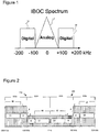
- Figure 1 shows a simplified form of one type of IBOC signal, which is the so-called “Hybrid IBOC FM” signal, and is denoted “Hybrid IBOC” in this document.
- Frequency is shown on the horizontal axis, with 0 Hz representing the carrier frequency.
- the vertical dimension of Figure 1 represents power.
- the hybrid signal is a combination / addition of an analogue FM-signal 10 and a digitally-modulated signal 12, 14.
- the analogue FM-signal 10 occupies a bandwidth of 200 kHz, which is between -100 kHz and 100 kHz, and represents a central-part that is centred on the carrier frequency.
- the digitally-modulated signal 12, 14 occupies a bandwidth of roughly 200 kHz.
- the digitally-modulated signal is separated into a lower-sideband 12 and an upper-sideband 14, each with a bandwidth of roughly 100 kHz.
- the lower-sideband is spectrally positioned at a distance of 100 kHz below the carrier-frequency.
- the upper-sideband 14 is spectrally positioned at a distance of 100 kHz above the carrier-frequency. In this way, the lower-sideband 12 is below the lowest frequency of the central-part, and the upper-sideband 14 is above the highest frequency of the central-part.
- the digitally-modulated signal 12, 14 can use orthogonal frequency division multiplexing (OFDM), where the number of subcarriers can vary depending on the selected service/transmission-mode.
- OFDM orthogonal frequency division multiplexing
- the total power of the digitally-modulated signal 12, 14 can be approximately a factor of a hundred smaller than the power of the analogue host-FM-signal 10.
- the hybrid IBOC signal can therefore be considered as a noisy FM-signal.
- a so-called "channel-grid” defines a reserved channel-bandwidth for an analogue FM-signal.
- the channel bandwidth in Band-II is 200 kHz by regulation, as shown by the analogue central part 10 in Figure 1 .
- the lower and upper digital OFDM-sidebands 12, 14 can correspond to the frequency range of 1st adjacent lower and upper neighbouring FM-channels.
- Figure 2 shows a spectrum plot of an all-digital implementation of an IBOC signal.
- the analogue FM-signal is replaced by a (secondary) digitally-modulated signal 220b, 222b.
- the bandwidth of the primary digital sidebands 220a, 222a is fully expanded with lower-power secondary sidebands.
- the all-digital IBOC signal has a bandwidth of roughly 400 kHz. Approximately 100 kHz of each of the lower and upper adjacent channels is occupied (that is, the frequencies that are outside the 200 kHz "channel-grid").
- the lower digital sideband of the all-digital IBOC signal is shown as 220 and the upper digital sideband is shown as 222. Each has a primary section 220a, 222a and a secondary section 220b, 222b.
- the number of extended frequency partitions (E) is fixed to 4. In a hybrid-mode system, for example as shown in Figure 1 , the number of extended frequency partitions (E) can be; 0, 1, 2, or 4, depending on the transmitted service mode.
- Log-likelihood ratios can be computed for decoding complementary punctured-pair convolutional codes (CPPC-codes) for In-band/on-channel (IBOC) transmissions.
- CPPC-codes complementary punctured-pair convolutional codes
- IBOC In-band/on-channel
- a Viterbi-decoder can then decode the LLRs in order to obtain an output signal.
- FIG. 3 shows an example embodiment of a block diagram of a two-path CIC receiver system.
- the receiver system includes an antenna 302 that is coupled to an RF-block 304, which includes a radio front-end (RFE).
- the RFE provides an analogue I/Q signal to an A/D block 306.
- the A/D block 306 provides a digital I/Q signal to a baseband block 308.
- the baseband block 308 includes a digital front-end (DFE), which provides another digital I/Q signal to a co-channel-interference-compensation-block 310, which in this example performs a COntinuous Look Through (COLT) algorithm for co-channel-interference compensation (CIC).
- DFE digital front-end
- the co-channel-interference-compensation-block 310 provides a first digital I/Q signal 312 and a second digital I/Q signal 314 to a H(IBOC)-receiver block 316 for OFDM demodulation and decoding. These two digital I/Q signals can be decoded by separate receiver chains.
- the H(IBOC)-receiver block 316 in this example does not include interference compensation.
- a second path which provides the second digital I/Q signal 314, is made available after the band-separation filter 308 or the "isolation-filters".
- the H(IBOC)-receiver block 316 can process this second digital I/Q signal 314, in order to perform FFT (OFDM-processing), do demodulation, perform channel-estimation, and compute soft-decision-information (i.e., LLRs) of each coded-bit.
- FFT OFDM-processing
- do demodulation perform channel-estimation
- compute soft-decision-information i.e., LLRs
- This CIC can be based on the so called; "COntinuous-Look-Through ( COLT ) -principle", which is described in US-patent: US 6,259,893 B1 , "Method and Apparatus for Reduction of FM Interference for FM In-Band On-Channel Digital Audio Broadcasting System", July 2001, Kroeger et.al.
- the LLRs for the Viterbi-decoder are obtained by combining the soft-decision bit-metrics of each of the paths. This combining is performed as an addition in the frequency-domain of the LLR-values of the 1 st -path and the 2 nd -path, i.e., after Channel-State-Information (CSI) estimation within the H(IBOC)-receiver block 316.
- CSI Channel-State-Information
- CP cyclic prefix
- ISI Inter-Symbol-Interference
- ICI Inter-Carrier-Interference
- the improved LLR-values may be referred to as advanced log-likelihood ratios (ALLRs).
- ALLRs advanced log-likelihood ratios
- the H(IBOC)-receiver block 316 can calculate the ALLRs by processing a single digital I/Q signal 312. That is, a second digital I/Q signal 314 would no longer be required. Therefore, the H(IBOC)-receiver block 316 would only require a single receiver chain.
- FIG 4 shows a receiver circuit 400, which can perform at least some of the functionality of an H(IBOC)-receiver block, such as the one illustrated in Figure 3 .
- the receiver circuit 400 does not require both of the two digital I/Q signals that are provided as an input signals in Figure 3 .
- the receiver circuit includes an averaging-processing-block 402 that receives an OFDM signal 404.
- the OFDM signal 404 includes a plurality of sample-values.
- the samples that are processed by the averaging-processing-block 402 can be in the frequency-domain.
- these frequency-domain samples represent the subcarriers of OFDM-symbols, which also provide time-behaviour (information) by the sequential order of the OFDM-symbols. Therefore, the plurality of sample-values that are processed by the averaging-processing-block 402 can be considered as being spaced apart in the time domain, even though they represent information in the frequency domain.
- the sample-values can be channel-estimate-sample-values that are representative of an estimate for the transfer function of the channel for each received sample, or (ii) the sample-values can be noise-estimate-sample-values that are representative of an estimate for a noise signal that is present in each sample.
- the averaging-processing-block 402 is configured to determine an averaged-sample-value for each received sample, and then provide an averaged-sample-output-signal 406 that includes the averaged-sample-values.
- the averaged-sample-output-signal 406 can then be used by other components (not shown in Figure 4 ) in the receiver circuit 400 in order to perform demodulation and decoding. Examples of such "other components" will be discussed in detail below with reference to Figure 5 .
- a total number of N sample-values of the OFDM signal 404 is processed by the averaging-processing-block 402 in order to determine an averaged-sample-value for each received sample.
- the N sample-values for each averaging operation can be considered as comprising: a middle-sample-value (n); a lower-sample-value-group; and a higher-sample-value-group. Sample-values for samples in the lower-sample-value-group have been received earlier in time than the middle-sample-value. Sample-values for samples in the higher-sample-value-group have been received later in time than the middle-sample-value.
- frequency-domain samples that have a sequential-order can be used for averaging, wherein the sequential-order represents earlier and later in time.
- the first frequency-domain samples represent the first received, and thus transmitted, (in time-order) OFDM-symbol.
- the lower-sample-value-group and the higher-sample-value-group contain the same number of sample values, and N is assumed to be an odd number for convenience. Therefore, the lower-sample-value-group can be defined as sample values between (n-((N-1)/2) and (n-1); and the higher-sample-value-group can be defined as sample values between (n+1) and (n+((N-1)/2)).
- the averaging-processing-block 402 is configured to determine the averaged-sample-value for the middle-sample-value (n) by performing an averaging operation on the sample-values of the lower-sample-value-group and the higher-sample-value-group, but not on the middle-sample-value.
- the averaging operation may be the calculation of a mean. It has been surprisingly found that by omitting the middle-sample-value from the averaging operation, the receiver circuit 400 can more accurately demodulate and decode an OFDM signal. This surprising result will be discussed in detail mathematically with reference to Figure 5 , and is also illustrated graphically in Figure 6 .
- the processing of the averaging-processing-block 402 may also be referred to as an extrinsic information averaging ( "Exia” ) technique.
- This approach can be considered similar to the usage of "extrinsic-information" in an iterative-setting because a sample of interest is not included in the averaging process; instead only the “neighbours" of the sample / data-symbol of interest are included.
- Figure 5 shows a receiver circuit 100 that includes two averaging-processing-blocks that provide the functionality of Figure 4 : an Exia-channel-estimator (channel-averaging-processing-block) 104 and an Exia-noise-estimator (noise-averaging-processing-block) 109.
- an Exia-channel-estimator channel-averaging-processing-block
- an Exia-noise-estimator noise-averaging-processing-block
- the receiver circuit 100 receives a noisy input-OFDM-signal 112 ( x n [ i ]), where i is the index in the time domain.
- the noisy input-OFDM-signal 112 ( x n [ i ]) includes information that is representative of reference-symbols and data-symbols, as will be discussed below.
- the receiver circuit 100 provides, as output signals, a first-output-LLR-signal L ⁇ k + l I n 114a, and a second-output-LLR-signal L ⁇ k + l Q n 114b.
- the receiver circuit 100 of Figure 5 can achieve a low bit error rate (BER) for a given signal-to-noise-ratio SNR, or can achieve a low SNR for a given BER. In this way, the sensitivity of the receiver circuit 100 can be improved.
- BER bit error rate
- the digitally modulated lower-and upper sidebands are based on a specific form of Coded-OFDM (COFDM).
- COFDM Coded-OFDM
- the two (upper and lower) 1st-adjacent FM-signals are co-channel interference-signals for the digitally-modulated COFDM-signals, since they reside on the lower and upper side-bands of the (H)IBOC transmitted signal.
- the (H)IBOC-system associated with the receiver circuit 100 of Figure 5 does not apply the conventional Rate-Compatible Punctured Conventional (RCPC)-codes.
- the (H)IBOC transmission-system uses a special kind of a convolutional-coding scheme, namely "Complementary Punctured-Pair Convolutional (CPPC)"-codes, which are robust against the 1st-adjacent FM-interference signals.
- CPPC-codes can be optimally decoded by a maximum a-posteriori probability (MAP) decoder or, to reduce complexity, by a maximum likelihood (ML) decoder, as is the case with conventional convolutional codes.
- MAP maximum a-posteriori probability
- ML maximum likelihood
- the Viterbi-decoding algorithm is an efficient ML-decoder for decoding convolutional codes, therefore, a Viterbi-engine can be provided downstream of the receiver circuit 100 such that it can decode the first-output-LLR-signal 114a and the second-output-LLR-signal 114b to determine the CPPC-codes.
- the (H)IBOC-system can use a tail-biting version of the convolutional-codes to be more efficient, especially for short code-words.
- a tail-biting convolutional decoder assumes that the begin-state of the code-word is identical to the end-state of the code-word. Consequently, the code word does not need to be expanded with tail-bits to force the convolutional-code to the zero-state at the end of the code-word.
- the tail-biting Viterbi-decoding computes the most likely bit-sequence with the probability of each coded-bit, i.e., soft-decision bit-metrics or "soft- decision Viterbi-decoding".
- This soft-decision bit information is based on the log-likelihood ratio (LLR) of each coded-bit, as provided by the first-output-LLR-signal 114a and the second-output-LLR-signal 114b, which can be sufficient information to obtain maximum-likelihood performances for decoding convolutional codes.
- LLR log-likelihood ratio
- the receiver circuit 100 of Figure 5 can perform an advanced log-likelihood ratio (ALLR) computation to generate the first-output-LLR-signal 114a and the second-output-LLR-signal 114b signals for use by a soft-decision (tail-biting) Viterbi-decoder.
- ALLR log-likelihood ratio
- the computation of these advanced LLRs includes one or more of the following beneficial algorithms:
- ALLR-computations do not make use of any feedback of the decoded bits; they do not require "iterative decoding of CPPC-codes", that is, CPPC-codes with iterative decoding (CPPC-ID).
- CPPC-ID iterative decoding
- the newly-proposed ALLR algorithms can be combined with iterative decoding techniques in some applications.
- the receiver circuit 100 of Figure 5 includes an overlap-and-add-processor 101.
- the overlap-and-add-processor 101 determines a centre-of-mass of the plurality of time-domain-samples of the input-OFDM-signal 112 ( x n [ i ]), and then performs an overlap-and-add operation on the input-OFDM-signal 112 ( x n [ i ]) based on the determined centre-of-mass in order to provide a processed-OFDM-signal ( x ⁇ n [ i ]), which includes a plurality of processed-time-domain-samples.
- a domain-converter 102 converts the processed-time-domain-samples x ⁇ n [ i ] into: (a) a plurality of reference-sample-values ( r k [n]) ; and (b) a plurality of data-sample-values ( y k + l [n] ) in the frequency domain.
- the domain-converter 102 performs a Q-points FFT.
- the reference-sample-values ( r k [n] ) are processed by a channel-estimator 103, an Exia-channel-estimator 104 and an optional linear-interpolator 105 in order to determine interpolated-channel-estimates ( X k+l [n] ) .
- the interpolated-channel-estimates ( X k+l [n] ) may also be referred to as "channel-estimation-data".
- the channel-estimator 103 processes the reference-sample-values ( r k [n] ) and corresponding pilot-sample-values ( P k [n] ) in order to determine channel-estimate-sample-values ( ⁇ k [ n ]) .
- the Exia-channel-estimator 104 then performs an averaging operation on the channel-estimate-sample-values ( ⁇ k [ n ]) in order to provide channel-estimates ( X k [n] ).
- the linear-interpolator 105 can use the channel estimates ( X k [n] ) to compute "interpolants", that is, "in-between-results".
- the linear-interpolator 105 provides interpolated-channel-estimates ( X k+l [n] ) as an output signal, which represent the determined characteristics of the channel, based on a comparison between the reference-sample-values ( r k [n] ) and the pilot-sample-values ( P k [n] ).
- the data-sample-values ( y k + l [n] ) are processed by a virtual-pilot-signal-generator 116, a noise-estimator 108, an Exia-noise-estimator 109 and a CSI-estimator 110 in order to determine channel-state information ( ⁇ k + l [ n ]).
- the virtual-pilot-signal-generator 116 generates "virtual-pilots" ( D ⁇ k + l [ n ]) for the data-sample-values ( y k + l [n] ) based on the data-sample-values ( y k + l [n] ) and the interpolated-channel-estimates ( X k + l [n] ) .
- the noise-estimator 108 processes the data-sample-values ( y k + l [n] ) and corresponding "virtual-pilots" ( D ⁇ k + l [ n ]) in order to determine noise-samples ( N ⁇ k + l [ n ]).
- the Exia-noise-estimator 109 then performs an averaging operation on the noise-samples ( N ⁇ k + l [ n ]) in order to provide noise-variance VAR ⁇ k + l 2 n .
- the CSI-estimator 110 then processes the noise-variance VAR ⁇ k + l 2 n and the interpolated-channel-estimates ( X k + l [n] ) in order to determine the channel-state information ( ⁇ k + l [ n ]).
- more accurate channel-state information can be generated using the data-sample-values, rather than the reference-sample-values, because typically there will be more data-samples than reference-samples available for processing. Therefore, no interpolation may be required by processing the reference-samples. However, the received data-samples are mapped into "virtual-pilots".
- an LLR-calculator 111 processes the interpolated-channel-estimates ( X k + l [n] ), the channel-state information ( ⁇ k + l [ n ]), and the data-sample-values ( y k + l [n] ) in order to determine the first-output-LLR-signal L ⁇ k + l I n 114a and the second-output-LLR-signal L ⁇ k + l Q n 114b for the received data-sample-values ( y k + l [n] ).
- CoM Center-of-Mass
- OaA Overlap-and-Add
- the overlap-and-add-processor 101 receives the input-OFDM-signal 112 ( x n [ i ]), which as discussed above includes a plurality of time-domain-samples.
- the overlap-and-add-processor 101 determines a centre-of-mass of the plurality of time-domain-samples, and then performs an overlap-and-add operation on the input-OFDM-signal 112 ( x n [ i ]) based on the determined centre-of-mass in order to provide a processed-OFDM-signal ( x ⁇ n [ i ]), which includes a plurality of processed-time-domain-samples.
- the center of mass (CoM) technique/algorithm takes into account the delay-spread of the channel and attempts to place the largest part of the channel energy into a guard-window, i.e., the center of the safe range (nominal position).
- ⁇ is the real-part of a complex number
- x n [ i ] the OFDM-symbol sample-value.
- Eq. 2 gives the distance of the CoM in samples from the start of one OFDM-symbol.
- the CoM algorithm derives an error signal indicating the current symbol timing position relative to the desired position.
- the output of the IFFT-process i.e., the time-domain output of the OFDM-symbol signal-generation
- the output of the IFFT-process can be shaped with a specific pulse.
- This pulse-shaping is applied to have a smoother transition, in the time-domain, from one OFDM-symbol to the next OFDM-symbol.
- This smoother transition in the time-domain results in the out of band power of the OFDM-signal being limited. Note, that this is desirable since the digitally-modulated OFDM-signals are combined with the analog host signal in the hybrid-mode, as shown in Figure 1 .
- the out of band power might "interfere" with the 1 st -adjacent FM (neighbour) signals, since they are co-channeled with the primary sidebands, e.g., sections 220a and 222a in Figure 2 .
- Applying pulse-shaping of the OFDM-symbol will result in reducing the total transmitted energy of the OFDM-symbol compared to if a "brick-wall" pulse-shape (actually, no pulse-shaping) was applied, i.e., the total energy is transmitted.
- the shape-curve occupies half the guard length.
- an "Overlap-and-Add (OaA)" technique can be applied at the receiver-side before the FFT-operation that is performed by the domain-converter 102.
- a conventional OaA-technique copies the last guard-time samples of the OFDM-symbol and adds these to the first guard-time samples of the OFDM-symbol to restore the energy, this yields;
- N g def x n B + x n E x ⁇ n Q + 1 :
- N s def x n E + x n B , n ⁇ Z
- N g is the number of cyclic-prefix or guard-samples
- Q is the number of samples of the FFT-length
- the FFT-window will start at the beginning of the OFDM-symbol. This is a preferable scenario if and only if there is no (or at least quite small) multipath, i.e., the maximal delay-spread of the channel is small. However, if this assumption of a small maximal delay-spread does not hold, then the start of the FFT-window should be shifted to a new-position that takes into account the delay-spread of the channel and attempts to place the largest part of the channel energy into the guard-window. This, as stated in the beginning of this section, is the objective of the CoM-algorithm.
- the pulse-shaping reduces the available energy within the guard-period. Therefore, a trade-off can be made between allowing energy of the previous OFDM-symbol to interfere (inter-symbol interference - ISI), and losing energy of the current OFDM-symbol by pulse-shaping.
- the overlap-and-add-processor of Figure 5 enables such a trade-off between ISI and energy-loss to be achieved by applying a CoM-dependent Overlap-and-Add technique. That is, it performs a partial overlap and add.
- This partial overlap and add technique starts at the CoM-position and ends at the end of cyclic-prefix, i.e., at the last sample of the guard-period.
- This newly-proposed technique we call; "Center-of-Mass (CoM) dependent Overlap-and-Add (OaA)" technique because the overlap-and-add is performed in accordance with a determined centre-of-mass. More specifically, the newly proposed algorithm sets an OaA-cut-off, which defines a boundary within the guard samples between: (i) a first set of guard samples; and (ii) a second set of guard samples, wherein the sample-values of the first set of guard samples will be copied to the sample-values of the second set of guard samples.
- the overlap-and-add-processor 101 can advantageously set the OaA-cut-off based on the determined centre-of-mass in order to make an acceptable trade-off between ISI and lost energy due to pulse-shaping.
- the CoM can define starting and end-points for performing the overlap-and add, which can be different to those that would be determined by a conventional OaA algorithm.
- this technique corresponds to the functionality of the averaging-processing-block of Figure 4 .
- the Exia averaging-technique will be applied for the channel-estimation (as performed by the Exia-channel-estimator 104) and also for the Noise-variance computation (as performed by the Exia-noise-estimator 109).
- received reference-symbols can be compared with expected pilot symbols.
- the received reference-symbols ( r k [ n ]) are provided by the domain-converter 102, and a BPSK-pilot on OFDM-subcarrier with index k and for the n th OFDM-symbol, P k n ⁇ 2 e j ⁇ 4 , 2 e j 5 ⁇ ⁇ 4 , is also known.
- the channel-estimator 103 of Figure 5 that receives: (i) an OFDM signal that comprises a plurality of reference-sample-values / reference-symbols ( r k [n] ); and (ii) an OFDM signal that comprises a plurality of pilot-sample-values ( P k [n] ), wherein the pilot-sample-values ( P k [n] ) correspond to the received reference-sample-values ( r k [n] ).
- the channel-estimator 103 processes the pilot-sample-values ( P k [n] ) and the received reference-sample-values ( r k [n] ) in order to determine a plurality of channel-estimate-sample-values ( ⁇ k [ n ]).
- N noise-samples are computed and a conventional statistical-average (i.e., the mean-value) over the squared absolute value of these N noise-samples is taken.
- Exia processing is defined as an averaging operation that does not include the middle-sample-value / sample of interest.
- equations 13 to 24 have been expressed in such a way that they can be used to illustrate how the "Exia” processing can improve the performance of the receiver circuit 100. Representing the equations in this way would not be obvious to the person skilled in the art based solely on well-known equations for calculating the mean of sample-values.
- Eq. 13 separately shows (i) the processing for the upper- and lower-sample-value-groups as the second term on the right-hand side of the equals sign; and (ii) the processing for the middle-sample-value as the first term on the right-hand side of the equals sign.
- Eq. 13 is artificially expressed in this in order assist the description of the "Exia" processing that will follow below.
- Eq. 18 also reveals that for smaller N, i.e., if less-averaging is applied, the CSI will grow due to the proportional-term N 1 ⁇ 1 N 2 within the denominator. Note, that the CSI scales the reliability of a bit, i.e., it scales the soft-decision information. Thus, it is rather contradictory that less noise-averaging results in a better reliability, i.e., more reliable soft-decision information.
- l indicates the OFDM-subcarrier index offset with respect to the reference-symbol at OFDM-subcarrier k up to the reference-symbol at OFDM-subcarrier k + L, i.e., the data-symbols are spectrally in between these two reference-symbols.
- the QPSK data-symbols ( y k + l [ n ]) are provided as an output signal from the domain-converter 102.
- H ⁇ k + l n ⁇ 1 ⁇ ⁇ l ⁇ H ⁇ k n ⁇ + ⁇ l ⁇ H ⁇ k + L n ⁇ , l ⁇ 1,2 , ⁇ , L ⁇ 1 , n ⁇ Z
- CSI ⁇ k + l n 1 ⁇ ⁇ l ⁇ CSI ⁇ k n + ⁇ l ⁇ CSI ⁇ k + L n , l ⁇ 1,2 , ⁇ , L ⁇ 1 , n ⁇ Z
- ⁇ l l L .
- Exia Extrinsic-information-averaging
- the Exia-channel-estimator 104 applies Exia on the channel-estimates ⁇ ⁇ k [ n ] ⁇ that are provided by the channel-estimator 103 based on the received reference-symbols ( r k [n] ) (see also Eq. 11) in order to obtain better estimates of the channel-coefficients in a noisy-environment.
- the linear-interpolator 105 applies an equation that is similar to that of Eq. 22 to the channel-estimates ( X k [ n ]) that are provided by the channel-averaging-processing-block 104. In this way, the linear-interpolator 105 can interpolate between a plurality of averaged-channel-estimate-sample-values ( X k [ n ]) in order to determine the interpolated-channel-estimates ( X k+l [n] ) (which can also be referred to as channel-estimation-data).
- equations 26 and 27 are shown to illustrate how noise-variance VAR ⁇ k 2 n and channel-state-information ( ⁇ k [ n ]) could be determined using reference-symbols.
- the processing of equations 26 and 27 is not performed by the receiver circuit 100 of Figure 5 however because, as will be discussed below, "virtual-pilots" are used to determine noise-variance and channel-state-information.
- the Exia processing described herein is particularly advantageous if the middle-sample-value corresponds to a pilot-sample-value, which includes a "virtual-pilot" sample-value as it is disclosed herein.
- noise-samples ( N ⁇ k + l [ n ]) are provided as an output signal from the noise-estimator 108.
- the noise-estimator 108 receives channel-estimation-data ( X k + l [ n ]); a plurality of N channel-estimated-data-sample-values ( D ⁇ k + l [ n ]); and an OFDM signal that comprises the plurality of N data-sample-values ( y k + l [ n ]).
- the noise-estimator 108 can then process the channel-estimation-data ( X k + l [ n ]); the channel-estimated-data-sample-values ( D ⁇ k + l [ n ]); and the N data-sample-values ( y k + l [ n ]) in order to determine a plurality of N noise-estimate-sample-values ( N ⁇ k + l [ n ]).
- the noise-variance VAR ⁇ k + l 2 n is provided as an output signal of the Exia-noise-estimator 109 in Figure 5 .
- the Exia-noise-estimator 109 receives an OFDM signal that comprises a plurality of N noise-estimate-sample-values ( N ⁇ k + l [ n ]), wherein the N samples comprise: a middle-noise-estimate-sample (n); a lower-noise-estimate-sample-group (n-((N-1)/2) to n-1); and a higher-noise-estimate-sample-group (n+1 to n+((N-1)/2)).
- the Exia-noise-estimator 109 can then determine an averaged-noise-estimate-sample-value VAR ⁇ k + l 2 n for the middle-noise-estimate-sample (n) by performing an averaging operation on the sample-values of the lower-noise-estimate-sample-group and the higher-noise-estimate-sample-group, but not on the sample-value of the middle-noise-estimate-sample.
- Eq. 30 shows the more consistent result that by increasing N the CSI also might increase due to the factor (N - 1) for N > 1. This is in contrast to non-Exia averaging, where increasing N seemingly decreased the value for the CSI.
- the CSI-estimator 110 can process an averaged-channel-estimate-sample-value ( X k + l [ n ]) and an averaged-noise-estimate-sample VAR ⁇ k + l 2 n in order to determine channel-state information ( ⁇ k + l [ n ]).
- the "Exia"-method based CSI-results ( ⁇ k + l [ n ]) are applied by the LLR-calculator 111 to compute the LLRs of the data-symbols ( y k + l [ n ]) that were received as part of the input-OFDM-signal 112.
- the LLR-calculator 111 splits the ALLR computation into real and imaginary values: a first-output-LLR-signal L ⁇ k + l I n 114a, and a second-output-LLR-signal L ⁇ k + l Q n 114b, as can be seen at the output of the LLR-calculator 111.
- the LLR-calculator 111 can process the channel-state information ( ⁇ k + l [ n ]), the averaged-channel-estimate-sample-value ( X k + l [ n ]) and data-sample-values ( y k + l [ n ]) in order to determine an output-LLR-signal ( L ⁇ k + l I n and L ⁇ k + l Q n ) .
- the virtual-pilot-signal-generator 116 "blind-maps" the received QPSK data-symbols ( y k + l [ n ]) to their expected transmitted values based on the channel-estimation-data ( X k+l [n] ) that is determined using the reference-symbols ( r k [ n ]) and the pilot symbols ( P k [ n ]) by the Exia-channel-estimator 104 and the linear-interpolator 105.
- the received QPSK data-symbols ( y k + l [ n ]) are blind-mapped to one of the following set of constellation-points 2 e j ⁇ 4 , 2 e j 3 ⁇ 4 , 2 e j 5 ⁇ 4 , 2 e j 7 ⁇ 4 to act as pilot-symbols for the received QPSK data-symbols ( y k + l [ n ]), i.e., "virtual-pilof' sample values.
- the virtual-pilot-signal-generator 116 in this example includes a channel-equaliser 106 and a data-mapper 107 to perform this functionality.
- the channel-equaliser 106 receives channel-estimation-data ( X k + l [ n ]) and an OFDM signal that comprises a plurality of N data-sample-values ( y k + l [ n ]).
- the channel-equaliser 106 divides the plurality of N data-sample-values ( y k + l [ n ]) by the channel-estimation-data ( X k + l [ n ]) as part of the processing for determining a plurality of N channel-estimated-data-sample-values ( D ⁇ k + l [ n ]) as represented by Eq. 33, and provides this quotient as an output signal for the data-mapper 107.
- the data-mapper 107 then converts the output signal of the channel-equaliser 106 to the nearest one of a plurality of predetermined points of an associated shift keying map in order to determine a plurality of N channel-estimated-data-sample-values ( D ⁇ k + l [ n ]).
- the predetermined points are the centre-points of the symbol-values in the QPSK constellation map, and therefore represent a perfectly accurate symbol-value.
- a comparison between (i) the perfectly accurate symbol-value (as provided by the channel-estimated-data-sample-values ( D ⁇ k + l [ n ]); and (ii) the received data-sample-values ( y k + l [ n ]), can be used to determine the characteristics of noise that is experienced by the data-sample-values ( y k + l [ n ]).
- the blind-mapped received-symbols or “virtual data-pilots” ( D ⁇ k + l [ n ]), are used to estimate the noise-variance VAR ⁇ k + l 2 n and, consequently, the channel-state-information (CSI) ( ⁇ k + l [ n ]).
- This "data-decision directed (DD) CSI” will be used to compute ALLRs for each of the coded-bits, as can be seen from the receiver circuit 100 in Figure 5 .
- ALLR computations with the newly proposed DD-CSI approach for the real I -branch and for the imaginary Q-branchas are given by Eq. 31, respectively, Eq.32 of the previous section and these computations are represented by the LLR-calculator 111 of the receiver circuit 100 of Figure 5 .
- the ALLRs should outperform the conventional LLRs in the presence of strong 1 st -adjacent interference signals. If this is indeed the case then, the (H)IBOC-receiver with the newly-proposed techniques should require, for the same performance, a lower sensitivity than the conventional (H)IBOC-receiver, i.e., with the two-path CIC approach shown in Figure 3 , and without the newly-proposed techniques.
- Figure 6 shows the following plots of BER versus SNR:
- Figure 6 shows how a distinction can be made between the three different improvement algorithms and shows what each of these algorithms adds to the total sensitivity gain.
- the second plot 604 represents an ALLR baseline plot, It represents the performance of a system that performs additional processing (but not the ALLR processing that has been described with reference to Figure 5 ) when compared with the conventional LLR processing.
- additional processing is not relevant to the present disclosure, apart from to mention that it was also performed by the systems that were used to generate the third plot 606, the fourth plot 608 and the fifth plot 610.
- the 1 st -algorithm; Center-of-Mass (CoM) dependent Overlap-and-Add (OaA), which is represented by the third plot 606, provides results that are substantially the same as those of the second plot 604.
- the Center-of-Mass (CoM) dependent Overlap-and-Add (OaA) does not improve the sensitivity-gain when compared with the second plot 604 because for the AWGN-case, the (optimal) CoM-position is at the beginning of the OFDM-symbol (which is a default assumption for a conventional system) due to zero-multipath.
- the third plot 606 would show an improved performance over the second plot 604.
- the 2 nd -algorithm which is represented by the fourth plot 608, shows, in this particular-case, a significant portion of the total sensitivity-gain, i.e., ⁇ 4.2 dB out of the ⁇ 4.7 dB when compared with the third plot 606.
- the 3 rd -algorithm (DD), which is represented by the fifth plot 610, shows a sensitivity-gain of ⁇ 0.5 dB at a moderate BER 10 -4 .
- DD 3 rd -algorithm
- the SNR sensitivity-values, i.e., the x-axis, shown by Figure 6 are based on the digital-signal processing that is modeled in the simulator, e.g., the isolation-filters are based on a suppression that looks to meet the overall BER-performances of a conventional (H)IBOC-receiver.
- the newly-proposed algorithms can only use information of the physical-layer (PHY) and may do not use information from the higher-layers.
- the newly-proposed algorithms may not use iterative-techniques based on reuse of the decoded information.
- the complexity of a receiver circuit as disclosed herein can be kept significantly lower compared to methods that use these higher-layers or iterative techniques.
- the above discussion mainly relates to QPSK, it will be appreciated that digital modulation schemes can be used, including other types of phase shift keying. Also, any degree of quadrature amplitude modulation (QAM) can be used. Furthermore, in some examples, the signals may not be OFDM signals.
- the set of instructions/method steps described above are implemented as functional and software instructions embodied as a set of executable instructions which are effected on a computer or machine which is programmed with and controlled by said executable instructions. Such instructions are loaded for execution on a processor (such as one or more CPUs).
- processor includes microprocessors, microcontrollers, processor modules or subsystems (including one or more microprocessors or microcontrollers), or other control or computing devices.
- a processor can refer to a single component or to plural components.
- the set of instructions/methods illustrated herein and data and instructions associated therewith are stored in respective storage devices, which are implemented as one or more non-transient machine or computer-readable or computer-usable storage media or mediums.
- Such computer-readable or computer usable storage medium or media is (are) considered to be part of an article (or article of manufacture).
- An article or article of manufacture can refer to any manufactured single component or multiple components.
- the non-transient machine or computer usable media or mediums as defined herein excludes signals, but such media or mediums may be capable of receiving and processing information from signals and/or other transient mediums.
- Example embodiments of the material discussed in this specification can be implemented in whole or in part through network, computer, or data based devices and/or services. These may include cloud, internet, intranet, mobile, desktop, processor, look-up table, microcontroller, consumer equipment, infrastructure, or other enabling devices and services. As may be used herein and in the claims, the following non-exclusive definitions are provided.
- one or more instructions or steps discussed herein are automated.
- the terms automated or automatically mean controlled operation of an apparatus, system, and/or process using computers and/or mechanical/electrical devices without the necessity of human intervention, observation, effort and/or decision.
- any components said to be coupled may be coupled or connected either directly or indirectly.
- additional components may be located between the two components that are said to be coupled.
Landscapes
- Engineering & Computer Science (AREA)
- Signal Processing (AREA)
- Computer Networks & Wireless Communication (AREA)
- Power Engineering (AREA)
- Quality & Reliability (AREA)
- Physics & Mathematics (AREA)
- Electromagnetism (AREA)
- Noise Elimination (AREA)
- Circuits Of Receivers In General (AREA)
Claims (10)
- Circuit récepteur (100) comprenant :
un processeur de chevauchement et d'addition, OaA (101), configuré pour :recevoir un signal OFDM d'entrée comprenant une pluralité d'échantillons de domaine temporel ;déterminer un centre de masse de la pluralité d'échantillons de domaine temporel ; eteffectuer une opération de chevauchement et d'addition sur le signal OFDM d'entrée sur la base du centre de masse déterminé afin de fournir un signal OFDM traité comprenant une pluralité d'échantillons de domaine temporel traités en :définissant un seuil d'OaA basé sur le centre de masse déterminé, qui définit une limite à l'intérieur des échantillons de garde entre : (i) un premier ensemble d'échantillons de garde ; et (ii) un second ensemble d'échantillons de garde ; où les échantillons de garde comprennent un préfixe cyclique du signal OFDM d'entrée ; etcopier les valeurs d'échantillons du second ensemble d'échantillons de garde dans les échantillons de données correspondants qui avaient été utilisés pour générer le second ensemble d'échantillons de garde dans le préfixe cyclique ;un convertisseur de domaine (102) configuré pour convertir les échantillons de domaine temporel traités en : (a) une pluralité de valeurs d'échantillons de référence ; et (b) une pluralité de valeurs d'échantillons de données dans le domaine fréquentiel ;un estimateur de canal (103) configuré pour :recevoir un signal OFDM qui comprend la pluralité de valeurs d'échantillons de référence ;recevoir un signal OFDM qui comprend une pluralité de valeurs d'échantillons pilotes, où les valeurs d'échantillons pilotes correspondent aux valeurs d'échantillons de référence reçues ; ettraiter les valeurs d'échantillons pilotes et les valeurs d'échantillons de référence reçues afin de déterminer une pluralité de valeurs d'échantillons d'estimation de canal ;un bloc de traitement de moyenne de canal (104) configuré pour :
recevoir un signal OFDM qui comprend la pluralité de valeurs d'échantillons d'estimation de canal, où les valeurs d'échantillons d'estimation de canal comprennent :un échantillon d'estimation de canal médian ;un groupe d'échantillons d'estimation de canal inférieur ; etun groupe d'échantillons d'estimation de canal supérieur ; etdéterminer une valeur d'échantillon d'estimation de canal moyennée pour l'échantillon d'estimation de canal médian en effectuant une opération de calcul de la moyenne sur les valeurs d'échantillons du groupe d'échantillons d'estimation de canal inférieur et du groupe d'échantillons d'estimation de canal supérieur, mais non sur la valeur d'échantillon de l'échantillon d'estimation de canal médian, où la valeur d'échantillon d'estimation de canal moyennée est représentative des données d'estimation de canal ;un générateur de signal pilote virtuel (116) configuré pour :recevoir les données d'estimation de canal ;recevoir un signal OFDM qui comprend la pluralité de valeurs d'échantillons de données ;diviser la pluralité de valeurs d'échantillon de données par les données d'estimation de canal ; etconvertir les résultats de la division en le point le plus proche d'une pluralité de points prédéterminés d'une carte de déplacement de phase associée afin de déterminer une pluralité de valeurs d'échantillons de données estimées de canal ;un estimateur de bruit (108) configuré pour :recevoir les données d'estimation de canal ;recevoir la pluralité de valeurs d'échantillons de données estimées de canal ;recevoir le signal OFDM qui comprend la pluralité de valeurs d'échantillons de données ; ettraiter les données d'estimation de canal, la pluralité de valeurs d'échantillons de données estimées de canal et le signal OFDM qui comprend la pluralité de valeurs d'échantillons de données afin de déterminer une pluralité de valeurs d'échantillons d'estimation de bruit ;un bloc de traitement de moyenne de bruit (109) configuré pour :
recevoir un signal OFDM qui comprend la pluralité de valeurs d'échantillons d'estimation de bruit, où les valeurs d'échantillons d'estimation de bruit comprennent :une valeur d'échantillon d'estimation de bruit médian ;un groupe de valeurs d'échantillons d'estimation de bruit inférieur ; etun groupe de valeurs d'échantillons d'estimation de bruit supérieur ; etdéterminer une valeur d'échantillon d'estimation de bruit moyennée pour la valeur d'échantillon d'estimation de bruit médian en effectuant une opération de calcul de la moyenne sur les valeurs d'échantillons d'estimation de bruit du groupe de valeurs d'échantillons d'estimation de bruit inférieur et du groupe de valeurs d'échantillons d'estimation de bruit supérieur, mais non sur la valeur d'échantillon d'estimation de bruit médian. - Circuit récepteur (100) selon la revendication 1, dans lequel les valeurs d'échantillons d'estimation de bruit sont représentatives d'une estimation de la puissance d'un signal de bruit qui est présent dans chaque échantillon.
- Circuit récepteur selon la revendication 1, dans lequel les valeurs d'échantillons d'estimation de canal sont représentatives d'une estimation pour la fonction de transfert du canal pour chaque échantillon reçu.
- Circuit récepteur selon l'une quelconque des revendications précédentes, dans lequel l'échantillon d'estimation de canal médian correspond à une valeur d'échantillon pilote connue.
- Circuit récepteur selon l'une quelconque des revendications précédentes, comprenant en outre :
un interpolateur linéaire (105) configuré pour procéder à une interpolation entre une pluralité de valeurs d'échantillons d'estimation de canal moyennées afin de déterminer les données d'estimation de canal. - Circuit récepteur selon l'une quelconque des revendications précédentes, comprenant en outre un estimateur CSI (110) configuré pour :
traiter la valeur d'échantillon d'estimation de canal moyennée et l'échantillon d'estimation de bruit moyenné afin de déterminer les informations d'état de canal. - Circuit récepteur selon la revendication 6, comprenant en outre un calculateur LLR (111) configuré pour :
traiter les informations d'état de canal, la valeur d'échantillon d'estimation de canal moyennée et des valeurs d'échantillon de données afin de déterminer un signal LLR de sortie. - Procédé de traitement d'un signal OFDM, le procédé comprenant les étapes suivantes :recevoir un signal OFDM d'entrée comprenant une pluralité d'échantillons de domaine temporel ;déterminer un centre de masse de la pluralité d'échantillons de domaine temporel ;exécuter une opération de chevauchement et d'addition, OaA, sur le signal OFDM d'entrée sur la base du centre de masse déterminé afin de fournir un signal OFDM traité comprenant une pluralité d'échantillons de domaine temporel traités en :définissant un seuil d'OaA basé sur le centre de masse déterminé, qui définit une limite à l'intérieur des échantillons de garde entre : (i) un premier ensemble d'échantillons de garde ; et (ii) un second ensemble d'échantillons de garde ; où les échantillons de garde comprennent un préfixe cyclique du signal OFDM d'entrée ; etcopier les valeurs d'échantillons du second ensemble d'échantillons de garde dans les échantillons de données correspondants qui avaient été utilisés pour générer le second ensemble d'échantillons de garde dans le préfixe cyclique ;convertir les échantillons de domaine temporel traités en : (a) une pluralité de valeurs d'échantillons de référence ; et (b) une pluralité de valeurs d'échantillons de données dans le domaine fréquentiel ;la réception d'un signal OFDM qui comprend une pluralité de valeurs d'échantillons pilotes, où les valeurs d'échantillons pilotes correspondent aux valeurs d'échantillons de référence ; ettraiter les valeurs d'échantillons pilotes et les valeurs d'échantillons de référence reçues afin de déterminer une pluralité de valeurs d'échantillons d'estimation de canal, où les valeurs d'échantillon d'estimation de canal comprennent :un échantillon d'estimation de canal médian ;un groupe d'échantillons d'estimation de canal inférieur ; etun groupe d'échantillons d'estimation de canal supérieur ; etdéterminer une valeur d'échantillon d'estimation de canal moyennée pour l'échantillon d'estimation de canal médian en effectuant une opération de calcul de la moyenne sur les valeurs d'échantillons du groupe d'échantillons d'estimation de canal inférieur et du groupe d'échantillons d'estimation de canal supérieur, mais non sur la valeur d'échantillon de l'échantillon d'estimation de canal médian, où la valeur d'échantillon d'estimation de canal moyennée est représentative des données d'estimation de canal ;diviser la pluralité de valeurs d'échantillon de données par les données d'estimation de canal ; etconvertir les résultats de la division en le point le plus proche d'une pluralité de points prédéterminés d'une carte de déplacement de phase associée afin de déterminer une pluralité de valeurs d'échantillons de données estimées de canal ;traiter les données d'estimation de canal, la pluralité de valeurs d'échantillons de données estimées de canal et la pluralité de valeurs d'échantillons de données afin de déterminer une pluralité de valeurs d'échantillons d'estimation de bruit, où les valeurs d'échantillons d'estimation de bruit comprennent : une valeur d'échantillon d'estimation de bruit médian ; un groupe de valeurs échantillons d'estimation de bruit inférieur ; et un groupe de valeurs échantillons d'estimation de bruit supérieur ;déterminer une valeur d'échantillon d'estimation de bruit moyennée pour la valeur d'échantillon d'estimation de bruit médian en effectuant une opération de calcul de la moyenne sur les valeurs d'échantillons d'estimation de bruit du groupe de valeurs d'échantillons d'estimation de bruit inférieur et du groupe de valeurs d'échantillons d'estimation de bruit supérieur, mais non sur la valeur d'échantillon d'estimation de bruit médian.
- Système de récepteur d'autoradio comprenant le circuit récepteur de l'une quelconque des revendications 1 à 7.
- Programme informatique comprenant des instructions qui, lorsqu'elles sont exécutées sur un ordinateur, amènent l'ordinateur à exécuter le procédé de la revendication 8.
Priority Applications (3)
| Application Number | Priority Date | Filing Date | Title |
|---|---|---|---|
| EP16181879.4A EP3276900B1 (fr) | 2016-07-29 | 2016-07-29 | Circuit récepteur |
| US15/641,881 US10382231B2 (en) | 2016-07-29 | 2017-07-05 | Receiver circuit |
| CN201710598043.8A CN107666456B (zh) | 2016-07-29 | 2017-07-20 | 接收器电路 |
Applications Claiming Priority (1)
| Application Number | Priority Date | Filing Date | Title |
|---|---|---|---|
| EP16181879.4A EP3276900B1 (fr) | 2016-07-29 | 2016-07-29 | Circuit récepteur |
Publications (2)
| Publication Number | Publication Date |
|---|---|
| EP3276900A1 EP3276900A1 (fr) | 2018-01-31 |
| EP3276900B1 true EP3276900B1 (fr) | 2020-02-19 |
Family
ID=56555308
Family Applications (1)
| Application Number | Title | Priority Date | Filing Date |
|---|---|---|---|
| EP16181879.4A Active EP3276900B1 (fr) | 2016-07-29 | 2016-07-29 | Circuit récepteur |
Country Status (3)
| Country | Link |
|---|---|
| US (1) | US10382231B2 (fr) |
| EP (1) | EP3276900B1 (fr) |
| CN (1) | CN107666456B (fr) |
Families Citing this family (3)
| Publication number | Priority date | Publication date | Assignee | Title |
|---|---|---|---|---|
| US10581476B2 (en) | 2018-05-17 | 2020-03-03 | Nxp B.V. | Beam forming for first adjacent cancellation |
| US12574174B2 (en) * | 2020-08-17 | 2026-03-10 | Qualcomm Incorporated | Reference signal configuration to account for a compression factor associated with transmit (TX) nonlinearity |
| US11438122B2 (en) * | 2021-06-14 | 2022-09-06 | Ultralogic 6G, Llc | Custom downlink search-spaces for low-complexity 5G/6G messaging |
Family Cites Families (23)
| Publication number | Priority date | Publication date | Assignee | Title |
|---|---|---|---|---|
| US6128355A (en) | 1997-05-21 | 2000-10-03 | Telefonaktiebolget Lm Ericsson | Selective diversity combining |
| US6167039A (en) | 1997-12-17 | 2000-12-26 | Telefonaktiebolget Lm Ericsson | Mobile station having plural antenna elements and interference suppression |
| US6795424B1 (en) | 1998-06-30 | 2004-09-21 | Tellabs Operations, Inc. | Method and apparatus for interference suppression in orthogonal frequency division multiplexed (OFDM) wireless communication systems |
| US6259893B1 (en) | 1998-11-03 | 2001-07-10 | Ibiquity Digital Corporation | Method and apparatus for reduction of FM interference for FM in-band on-channel digital audio broadcasting system |
| US6671340B1 (en) | 2000-06-15 | 2003-12-30 | Ibiquity Digital Corporation | Method and apparatus for reduction of interference in FM in-band on-channel digital audio broadcasting receivers |
| JP3782330B2 (ja) * | 2001-09-14 | 2006-06-07 | 富士通株式会社 | Ofdm受信方法及びofdm受信装置 |
| KR100560386B1 (ko) * | 2003-12-17 | 2006-03-13 | 한국전자통신연구원 | 무선 통신 시스템의 상향 링크에서 코히어런트 검출을위한 직교주파수 분할 다중 접속 방식의 송수신 장치 및그 방법 |
| KR20080021658A (ko) * | 2005-06-16 | 2008-03-07 | 코닌클리케 필립스 일렉트로닉스 엔.브이. | Csi기반 llr 메트릭스를 구비한 ofdm 수신기 |
| US20080056343A1 (en) * | 2006-08-30 | 2008-03-06 | Ravikiran Rajagopal | Frame synchronization |
| JP5609886B2 (ja) * | 2009-04-01 | 2014-10-22 | 日本電気株式会社 | Ofdmシステムにおける制御チャネルのためのチャネル推定 |
| GB2470758B (en) * | 2009-06-03 | 2014-08-20 | Sony Corp | Data processing apparatus and method |
| CN101924723B (zh) * | 2009-06-09 | 2013-05-08 | 中兴通讯股份有限公司 | Ofdm信号解调方法和装置 |
| US8416118B1 (en) * | 2010-03-05 | 2013-04-09 | Lockheed Martin Corporation | Chaff cloud detection and centroid estimation |
| JP2011237753A (ja) * | 2010-04-14 | 2011-11-24 | Sony Corp | 信号処理装置および方法、並びにプログラム |
| CN102263760B (zh) * | 2011-08-22 | 2013-09-25 | 宁波大学 | 一种抗噪声多媒体无线广播信号成帧调制方法 |
| US9325409B1 (en) | 2012-04-12 | 2016-04-26 | Tarana Wireless, Inc. | Non-line of sight wireless communication system and method |
| US9160430B2 (en) | 2012-04-13 | 2015-10-13 | Intel Corporation | Millimeter-wave transceiver with coarse and fine beamforming with interference suppression and method |
| US8811522B2 (en) | 2012-05-29 | 2014-08-19 | Magnolia Broadband Inc. | Mitigating interferences for a multi-layer MIMO system augmented by radio distribution network |
| US9191256B2 (en) | 2012-12-03 | 2015-11-17 | Digital PowerRadio, LLC | Systems and methods for advanced iterative decoding and channel estimation of concatenated coding systems |
| US9838100B2 (en) | 2014-11-18 | 2017-12-05 | Nxp B.V. | Beam forming with double-null-steering for in-band on-channel reception |
| GB2531367B (en) * | 2015-01-09 | 2016-12-28 | Imagination Tech Ltd | Impulsive noise rejection |
| EP3197058A1 (fr) | 2016-01-25 | 2017-07-26 | Nxp B.V. | Circuit récepteur |
| EP3244550A1 (fr) | 2016-05-13 | 2017-11-15 | Nxp B.V. | Circuit récepteur pour la compensation d'interférences de canal commun en bandes adjacentes |
-
2016
- 2016-07-29 EP EP16181879.4A patent/EP3276900B1/fr active Active
-
2017
- 2017-07-05 US US15/641,881 patent/US10382231B2/en not_active Expired - Fee Related
- 2017-07-20 CN CN201710598043.8A patent/CN107666456B/zh not_active Expired - Fee Related
Non-Patent Citations (1)
| Title |
|---|
| None * |
Also Published As
| Publication number | Publication date |
|---|---|
| US10382231B2 (en) | 2019-08-13 |
| CN107666456A (zh) | 2018-02-06 |
| EP3276900A1 (fr) | 2018-01-31 |
| CN107666456B (zh) | 2022-03-29 |
| US20180034670A1 (en) | 2018-02-01 |
Similar Documents
| Publication | Publication Date | Title |
|---|---|---|
| JP5717621B2 (ja) | 狭帯域干渉を受けるofdm信号を復号する方法 | |
| EP2378685A1 (fr) | Appareil émetteur, procédé d'émission, système de communication et procédé de communication | |
| US8050342B2 (en) | Method and apparatus for receiving coded signals with the aid of channel state information | |
| US8811545B2 (en) | Method for reducing interference in OFDM wireless networks | |
| TWI461006B (zh) | 無線通訊接收機、無線通訊接收方法與相位雜訊補償裝置 | |
| CN103609085B (zh) | 用于在无线通信系统中接收信号的装置和方法 | |
| US10003440B2 (en) | Receiver circuit | |
| US9031170B2 (en) | Channel frequency response estimator for a wireless RF channel | |
| US10382231B2 (en) | Receiver circuit | |
| EP2950491B1 (fr) | Système et procédé pour réaliser une estimation de canal sur un signal ofdm | |
| EP1748610B1 (fr) | Appareil, méthode et programme d'ordinateur pour estimer un canal pour un système de transmission OFDM | |
| US8249203B2 (en) | Truncation of noisy taps in channel estimation | |
| KR20100138341A (ko) | 오에프디엠 수신기에 적용되는 최대 채널 딜레이를 추정하는 방법 및 시피에버리징 방법 | |
| CN102265573B (zh) | 用于估计正交频分复用传输系统中相位噪声的方法和装置 | |
| CN119945622B (zh) | 一种电力无线专网pdsch物理信道资源映射方法 | |
| WO2011065878A1 (fr) | Normalisation de la valeur logicielle de bit | |
| KR20130070338A (ko) | Ofdm 시스템의 상호상관 기반 채널 추정 방법 및 그 장치 | |
| JP2010161648A (ja) | 通信システム、送信装置、受信装置、送信制御方法、受信制御方法、送信制御プログラム、受信制御プログラム | |
| US8284869B2 (en) | QAM demodulation | |
| Ogundile et al. | Improved reliability information for OFDM systems on time-varying frequency-selective fading channels | |
| JP6571605B2 (ja) | 無線受信方法および無線受信装置 | |
| EP1865678A1 (fr) | Système et procédé pour séparer deux signaux OFDM | |
| JP2011166329A (ja) | 等化処理装置及び受信装置 |
Legal Events
| Date | Code | Title | Description |
|---|---|---|---|
| PUAI | Public reference made under article 153(3) epc to a published international application that has entered the european phase |
Free format text: ORIGINAL CODE: 0009012 |
|
| STAA | Information on the status of an ep patent application or granted ep patent |
Free format text: STATUS: THE APPLICATION HAS BEEN PUBLISHED |
|
| AK | Designated contracting states |
Kind code of ref document: A1 Designated state(s): AL AT BE BG CH CY CZ DE DK EE ES FI FR GB GR HR HU IE IS IT LI LT LU LV MC MK MT NL NO PL PT RO RS SE SI SK SM TR |
|
| AX | Request for extension of the european patent |
Extension state: BA ME |
|
| STAA | Information on the status of an ep patent application or granted ep patent |
Free format text: STATUS: REQUEST FOR EXAMINATION WAS MADE |
|
| 17P | Request for examination filed |
Effective date: 20180731 |
|
| RBV | Designated contracting states (corrected) |
Designated state(s): AL AT BE BG CH CY CZ DE DK EE ES FI FR GB GR HR HU IE IS IT LI LT LU LV MC MK MT NL NO PL PT RO RS SE SI SK SM TR |
|
| STAA | Information on the status of an ep patent application or granted ep patent |
Free format text: STATUS: EXAMINATION IS IN PROGRESS |
|
| 17Q | First examination report despatched |
Effective date: 20190123 |
|
| GRAP | Despatch of communication of intention to grant a patent |
Free format text: ORIGINAL CODE: EPIDOSNIGR1 |
|
| STAA | Information on the status of an ep patent application or granted ep patent |
Free format text: STATUS: GRANT OF PATENT IS INTENDED |
|
| INTG | Intention to grant announced |
Effective date: 20191104 |
|
| GRAS | Grant fee paid |
Free format text: ORIGINAL CODE: EPIDOSNIGR3 |
|
| GRAA | (expected) grant |
Free format text: ORIGINAL CODE: 0009210 |
|
| STAA | Information on the status of an ep patent application or granted ep patent |
Free format text: STATUS: THE PATENT HAS BEEN GRANTED |
|
| AK | Designated contracting states |
Kind code of ref document: B1 Designated state(s): AL AT BE BG CH CY CZ DE DK EE ES FI FR GB GR HR HU IE IS IT LI LT LU LV MC MK MT NL NO PL PT RO RS SE SI SK SM TR |
|
| REG | Reference to a national code |
Ref country code: CH Ref legal event code: EP |
|
| REG | Reference to a national code |
Ref country code: DE Ref legal event code: R096 Ref document number: 602016029939 Country of ref document: DE |
|
| REG | Reference to a national code |
Ref country code: AT Ref legal event code: REF Ref document number: 1236240 Country of ref document: AT Kind code of ref document: T Effective date: 20200315 |
|
| REG | Reference to a national code |
Ref country code: IE Ref legal event code: FG4D |
|
| REG | Reference to a national code |
Ref country code: NL Ref legal event code: MP Effective date: 20200219 |
|
| PG25 | Lapsed in a contracting state [announced via postgrant information from national office to epo] |
Ref country code: NO Free format text: LAPSE BECAUSE OF FAILURE TO SUBMIT A TRANSLATION OF THE DESCRIPTION OR TO PAY THE FEE WITHIN THE PRESCRIBED TIME-LIMIT Effective date: 20200519 Ref country code: RS Free format text: LAPSE BECAUSE OF FAILURE TO SUBMIT A TRANSLATION OF THE DESCRIPTION OR TO PAY THE FEE WITHIN THE PRESCRIBED TIME-LIMIT Effective date: 20200219 Ref country code: FI Free format text: LAPSE BECAUSE OF FAILURE TO SUBMIT A TRANSLATION OF THE DESCRIPTION OR TO PAY THE FEE WITHIN THE PRESCRIBED TIME-LIMIT Effective date: 20200219 |
|
| REG | Reference to a national code |
Ref country code: LT Ref legal event code: MG4D |
|
| PG25 | Lapsed in a contracting state [announced via postgrant information from national office to epo] |
Ref country code: BG Free format text: LAPSE BECAUSE OF FAILURE TO SUBMIT A TRANSLATION OF THE DESCRIPTION OR TO PAY THE FEE WITHIN THE PRESCRIBED TIME-LIMIT Effective date: 20200519 Ref country code: IS Free format text: LAPSE BECAUSE OF FAILURE TO SUBMIT A TRANSLATION OF THE DESCRIPTION OR TO PAY THE FEE WITHIN THE PRESCRIBED TIME-LIMIT Effective date: 20200619 Ref country code: HR Free format text: LAPSE BECAUSE OF FAILURE TO SUBMIT A TRANSLATION OF THE DESCRIPTION OR TO PAY THE FEE WITHIN THE PRESCRIBED TIME-LIMIT Effective date: 20200219 Ref country code: LV Free format text: LAPSE BECAUSE OF FAILURE TO SUBMIT A TRANSLATION OF THE DESCRIPTION OR TO PAY THE FEE WITHIN THE PRESCRIBED TIME-LIMIT Effective date: 20200219 Ref country code: SE Free format text: LAPSE BECAUSE OF FAILURE TO SUBMIT A TRANSLATION OF THE DESCRIPTION OR TO PAY THE FEE WITHIN THE PRESCRIBED TIME-LIMIT Effective date: 20200219 Ref country code: GR Free format text: LAPSE BECAUSE OF FAILURE TO SUBMIT A TRANSLATION OF THE DESCRIPTION OR TO PAY THE FEE WITHIN THE PRESCRIBED TIME-LIMIT Effective date: 20200520 |
|
| PG25 | Lapsed in a contracting state [announced via postgrant information from national office to epo] |
Ref country code: NL Free format text: LAPSE BECAUSE OF FAILURE TO SUBMIT A TRANSLATION OF THE DESCRIPTION OR TO PAY THE FEE WITHIN THE PRESCRIBED TIME-LIMIT Effective date: 20200219 |
|
| PG25 | Lapsed in a contracting state [announced via postgrant information from national office to epo] |
Ref country code: ES Free format text: LAPSE BECAUSE OF FAILURE TO SUBMIT A TRANSLATION OF THE DESCRIPTION OR TO PAY THE FEE WITHIN THE PRESCRIBED TIME-LIMIT Effective date: 20200219 Ref country code: LT Free format text: LAPSE BECAUSE OF FAILURE TO SUBMIT A TRANSLATION OF THE DESCRIPTION OR TO PAY THE FEE WITHIN THE PRESCRIBED TIME-LIMIT Effective date: 20200219 Ref country code: RO Free format text: LAPSE BECAUSE OF FAILURE TO SUBMIT A TRANSLATION OF THE DESCRIPTION OR TO PAY THE FEE WITHIN THE PRESCRIBED TIME-LIMIT Effective date: 20200219 Ref country code: CZ Free format text: LAPSE BECAUSE OF FAILURE TO SUBMIT A TRANSLATION OF THE DESCRIPTION OR TO PAY THE FEE WITHIN THE PRESCRIBED TIME-LIMIT Effective date: 20200219 Ref country code: PT Free format text: LAPSE BECAUSE OF FAILURE TO SUBMIT A TRANSLATION OF THE DESCRIPTION OR TO PAY THE FEE WITHIN THE PRESCRIBED TIME-LIMIT Effective date: 20200712 Ref country code: SK Free format text: LAPSE BECAUSE OF FAILURE TO SUBMIT A TRANSLATION OF THE DESCRIPTION OR TO PAY THE FEE WITHIN THE PRESCRIBED TIME-LIMIT Effective date: 20200219 Ref country code: SM Free format text: LAPSE BECAUSE OF FAILURE TO SUBMIT A TRANSLATION OF THE DESCRIPTION OR TO PAY THE FEE WITHIN THE PRESCRIBED TIME-LIMIT Effective date: 20200219 Ref country code: EE Free format text: LAPSE BECAUSE OF FAILURE TO SUBMIT A TRANSLATION OF THE DESCRIPTION OR TO PAY THE FEE WITHIN THE PRESCRIBED TIME-LIMIT Effective date: 20200219 Ref country code: DK Free format text: LAPSE BECAUSE OF FAILURE TO SUBMIT A TRANSLATION OF THE DESCRIPTION OR TO PAY THE FEE WITHIN THE PRESCRIBED TIME-LIMIT Effective date: 20200219 |
|
| REG | Reference to a national code |
Ref country code: AT Ref legal event code: MK05 Ref document number: 1236240 Country of ref document: AT Kind code of ref document: T Effective date: 20200219 |
|
| REG | Reference to a national code |
Ref country code: DE Ref legal event code: R097 Ref document number: 602016029939 Country of ref document: DE |
|
| PLBE | No opposition filed within time limit |
Free format text: ORIGINAL CODE: 0009261 |
|
| STAA | Information on the status of an ep patent application or granted ep patent |
Free format text: STATUS: NO OPPOSITION FILED WITHIN TIME LIMIT |
|
| 26N | No opposition filed |
Effective date: 20201120 |
|
| PG25 | Lapsed in a contracting state [announced via postgrant information from national office to epo] |
Ref country code: IT Free format text: LAPSE BECAUSE OF FAILURE TO SUBMIT A TRANSLATION OF THE DESCRIPTION OR TO PAY THE FEE WITHIN THE PRESCRIBED TIME-LIMIT Effective date: 20200219 Ref country code: AT Free format text: LAPSE BECAUSE OF FAILURE TO SUBMIT A TRANSLATION OF THE DESCRIPTION OR TO PAY THE FEE WITHIN THE PRESCRIBED TIME-LIMIT Effective date: 20200219 |
|
| PG25 | Lapsed in a contracting state [announced via postgrant information from national office to epo] |
Ref country code: MC Free format text: LAPSE BECAUSE OF FAILURE TO SUBMIT A TRANSLATION OF THE DESCRIPTION OR TO PAY THE FEE WITHIN THE PRESCRIBED TIME-LIMIT Effective date: 20200219 Ref country code: SI Free format text: LAPSE BECAUSE OF FAILURE TO SUBMIT A TRANSLATION OF THE DESCRIPTION OR TO PAY THE FEE WITHIN THE PRESCRIBED TIME-LIMIT Effective date: 20200219 Ref country code: PL Free format text: LAPSE BECAUSE OF FAILURE TO SUBMIT A TRANSLATION OF THE DESCRIPTION OR TO PAY THE FEE WITHIN THE PRESCRIBED TIME-LIMIT Effective date: 20200219 |
|
| REG | Reference to a national code |
Ref country code: CH Ref legal event code: PL |
|
| REG | Reference to a national code |
Ref country code: BE Ref legal event code: MM Effective date: 20200731 |
|
| PG25 | Lapsed in a contracting state [announced via postgrant information from national office to epo] |
Ref country code: CH Free format text: LAPSE BECAUSE OF NON-PAYMENT OF DUE FEES Effective date: 20200731 Ref country code: LU Free format text: LAPSE BECAUSE OF NON-PAYMENT OF DUE FEES Effective date: 20200729 Ref country code: LI Free format text: LAPSE BECAUSE OF NON-PAYMENT OF DUE FEES Effective date: 20200731 |
|
| PG25 | Lapsed in a contracting state [announced via postgrant information from national office to epo] |
Ref country code: BE Free format text: LAPSE BECAUSE OF NON-PAYMENT OF DUE FEES Effective date: 20200731 |
|
| PG25 | Lapsed in a contracting state [announced via postgrant information from national office to epo] |
Ref country code: IE Free format text: LAPSE BECAUSE OF NON-PAYMENT OF DUE FEES Effective date: 20200729 |
|
| PG25 | Lapsed in a contracting state [announced via postgrant information from national office to epo] |
Ref country code: TR Free format text: LAPSE BECAUSE OF FAILURE TO SUBMIT A TRANSLATION OF THE DESCRIPTION OR TO PAY THE FEE WITHIN THE PRESCRIBED TIME-LIMIT Effective date: 20200219 Ref country code: MT Free format text: LAPSE BECAUSE OF FAILURE TO SUBMIT A TRANSLATION OF THE DESCRIPTION OR TO PAY THE FEE WITHIN THE PRESCRIBED TIME-LIMIT Effective date: 20200219 Ref country code: CY Free format text: LAPSE BECAUSE OF FAILURE TO SUBMIT A TRANSLATION OF THE DESCRIPTION OR TO PAY THE FEE WITHIN THE PRESCRIBED TIME-LIMIT Effective date: 20200219 |
|
| PG25 | Lapsed in a contracting state [announced via postgrant information from national office to epo] |
Ref country code: MK Free format text: LAPSE BECAUSE OF FAILURE TO SUBMIT A TRANSLATION OF THE DESCRIPTION OR TO PAY THE FEE WITHIN THE PRESCRIBED TIME-LIMIT Effective date: 20200219 Ref country code: AL Free format text: LAPSE BECAUSE OF FAILURE TO SUBMIT A TRANSLATION OF THE DESCRIPTION OR TO PAY THE FEE WITHIN THE PRESCRIBED TIME-LIMIT Effective date: 20200219 |
|
| PGFP | Annual fee paid to national office [announced via postgrant information from national office to epo] |
Ref country code: GB Payment date: 20220621 Year of fee payment: 7 |
|
| PGFP | Annual fee paid to national office [announced via postgrant information from national office to epo] |
Ref country code: FR Payment date: 20220621 Year of fee payment: 7 |
|
| PGFP | Annual fee paid to national office [announced via postgrant information from national office to epo] |
Ref country code: DE Payment date: 20220621 Year of fee payment: 7 |
|
| REG | Reference to a national code |
Ref country code: DE Ref legal event code: R119 Ref document number: 602016029939 Country of ref document: DE |
|
| GBPC | Gb: european patent ceased through non-payment of renewal fee |
Effective date: 20230729 |
|
| PG25 | Lapsed in a contracting state [announced via postgrant information from national office to epo] |
Ref country code: DE Free format text: LAPSE BECAUSE OF NON-PAYMENT OF DUE FEES Effective date: 20240201 Ref country code: GB Free format text: LAPSE BECAUSE OF NON-PAYMENT OF DUE FEES Effective date: 20230729 |
|
| PG25 | Lapsed in a contracting state [announced via postgrant information from national office to epo] |
Ref country code: FR Free format text: LAPSE BECAUSE OF NON-PAYMENT OF DUE FEES Effective date: 20230731 |