EP3276909B1 - Dispositif d'authentification - Google Patents
Dispositif d'authentification Download PDFInfo
- Publication number
- EP3276909B1 EP3276909B1 EP17001286.8A EP17001286A EP3276909B1 EP 3276909 B1 EP3276909 B1 EP 3276909B1 EP 17001286 A EP17001286 A EP 17001286A EP 3276909 B1 EP3276909 B1 EP 3276909B1
- Authority
- EP
- European Patent Office
- Prior art keywords
- security element
- response signal
- request signal
- signal
- supplied
- Prior art date
- Legal status (The legal status is an assumption and is not a legal conclusion. Google has not performed a legal analysis and makes no representation as to the accuracy of the status listed.)
- Active
Links
Images

Classifications
-
- H—ELECTRICITY
- H04—ELECTRIC COMMUNICATION TECHNIQUE
- H04L—TRANSMISSION OF DIGITAL INFORMATION, e.g. TELEGRAPHIC COMMUNICATION
- H04L63/00—Network architectures or network communication protocols for network security
- H04L63/08—Network architectures or network communication protocols for network security for authentication of entities
- H04L63/0853—Network architectures or network communication protocols for network security for authentication of entities using an additional device, e.g. smartcard, SIM or a different communication terminal
-
- G—PHYSICS
- G06—COMPUTING OR CALCULATING; COUNTING
- G06F—ELECTRIC DIGITAL DATA PROCESSING
- G06F21/00—Security arrangements for protecting computers, components thereof, programs or data against unauthorised activity
- G06F21/30—Authentication, i.e. establishing the identity or authorisation of security principals
- G06F21/44—Program or device authentication
-
- H—ELECTRICITY
- H04—ELECTRIC COMMUNICATION TECHNIQUE
- H04L—TRANSMISSION OF DIGITAL INFORMATION, e.g. TELEGRAPHIC COMMUNICATION
- H04L63/00—Network architectures or network communication protocols for network security
- H04L63/08—Network architectures or network communication protocols for network security for authentication of entities
- H04L63/0876—Network architectures or network communication protocols for network security for authentication of entities based on the identity of the terminal or configuration, e.g. MAC address, hardware or software configuration or device fingerprint
-
- Y—GENERAL TAGGING OF NEW TECHNOLOGICAL DEVELOPMENTS; GENERAL TAGGING OF CROSS-SECTIONAL TECHNOLOGIES SPANNING OVER SEVERAL SECTIONS OF THE IPC; TECHNICAL SUBJECTS COVERED BY FORMER USPC CROSS-REFERENCE ART COLLECTIONS [XRACs] AND DIGESTS
- Y04—INFORMATION OR COMMUNICATION TECHNOLOGIES HAVING AN IMPACT ON OTHER TECHNOLOGY AREAS
- Y04S—SYSTEMS INTEGRATING TECHNOLOGIES RELATED TO POWER NETWORK OPERATION, COMMUNICATION OR INFORMATION TECHNOLOGIES FOR IMPROVING THE ELECTRICAL POWER GENERATION, TRANSMISSION, DISTRIBUTION, MANAGEMENT OR USAGE, i.e. SMART GRIDS
- Y04S40/00—Systems for electrical power generation, transmission, distribution or end-user application management characterised by the use of communication or information technologies, or communication or information technology specific aspects supporting them
- Y04S40/20—Information technology specific aspects, e.g. CAD, simulation, modelling, system security
Definitions
- the present invention is directed to a method for authenticating a security element or a value document and enables users to identify themselves remotely from a verification point or an authentication point by means of a communication interface.
- the present invention is also directed to an appropriately configured authentication arrangement and to a computer program product with control commands which implement the method or operate the proposed authentication arrangement.
- DE 212012000065 U1 shows a token for strong authentication for the generation of dynamic security values using acoustic and optical signals.
- EP 2338126 B1 shows a method for a portable data carrier for releasing transaction data selected for processing. Here melodies are acoustically superimposed.
- EP 1333406 A1 shows a method for checking an authorization of a user of a terminal, wherein a signal acoustically transmitted by the terminal is compared by a signal detection device.
- EP 2559563 A1 shows a security method with optical features, wherein an image is provided which is optically subdivided into further method steps. These partial images are then arranged on transparent partial elements of a value document in such a way that, when viewed through them, they form the overall image.
- DE 10 2014 018861 A1 discloses various methods for online authentication of a security feature, which is arranged on a document, the methods using household hardware and in particular without a special card reader.
- XP055421076 cites the Wikipedia article with the title “Transaction number”, which among other things reveals the chip-tan process that is widespread in online banking.
- identity documents are known which, for example, have a photo of an identity card holder together with personalized data. Authentication takes place here in such a way that a cardholder physically provides or hands over the corresponding card or the value document. A person can now typically check whether the stored biometric features match the features of the actual cardholder. For this purpose, the testing person can use other technical end devices to read out or verify security features.
- Authentication systems are also known which are carried out via a data connection. This typically requires a secret key and a public key with which authentication takes place. Methods are known which, for example, require an e-mail address or a user name as a public key and furthermore require a PIN or password as a secret key. However, it is not possible to focus on the user as such. Rather, the case may arise that an unauthorized user can spy on a password and thus unauthorizedly activate a user account for sensitive data or a sensitive service.
- identification data or documents of value with a corresponding security element are typically not set up for remote authentication, ie for example authentication over a network.
- authentication via a network it is a particular security risk that the hardware components used are solely under administration of the user.
- no certification body provides certain, tested components, as is the case with an automated teller machine, for example.
- the user uses a conventional Internet interface and holds a camera and a screen in front of him, for example. In this way it is e.g. For example, it is possible for an attacker to incorrectly maintain security features as his own. An attacker can thus only provide an image or a video, based on which an attacker pretends to be a user who can actually be recognized on the video.
- a method for authenticating a security element or a value document comprises the steps of providing at least one request signal from a verification point to a terminal by means of a network. Furthermore, the provided request signal is read out by a security element and at least one response signal is generated by the security element using the provided at least one request signal. The at least one response signal generated is then transmitted from the security element to the verification point in order to compare the at least one response signal with a stored response signal.
- a security element can be included in a value document, for example, but the security element can also be the value document itself.
- an identification document which comprises further security features can be understood as a value document or a security element.
- Personalized data such as a photo, can be stored on an identification document.
- the photo serves as a possible security element.
- Further security elements are known to the person skilled in the art which can be provided on corresponding value documents.
- a document of value or a security element can be, for example, a credit card, a smart card or the like. It is advantageous according to the invention that the security element can use other components, such as a display, a controller, a photodiode, an LED and a battery. These components can be installed in the security element or are at least connected to the security element in such a way that the proposed method can be implemented.
- a user can use this security element to prove his identity to a verification body.
- the verification point is provided by a bank with which the user wants to authenticate himself. It is possible for the user to hold an identification document and thus identify or authenticate himself geographically distant from the bank. Consequently, according to the invention, an identity is verified by means of a computer network. It is possible that the user only operates his own hardware, i.e. H. that only typical network components, such as a computer with a screen and camera, are operated. It is particularly advantageous here that the proposed method can only be implemented with such household-typical hardware units, without the verification body, for example the bank, other hardware, such as, for. B. card readers must output.
- At least one request signal is made available from a verification point to a terminal by means of a network.
- the terminal can be, for example, a computer with a screen.
- a laptop is possible here, which also holds a camera in addition to the screen.
- the verification body calculates a request signal, which the user can use his terminal, e.g. B. the screen is provided. This can be done by means of data transmission over a network, preferably the Internet.
- the security element comprises a sensor arrangement or at least one sensor which is suitable for reading out the request signal.
- the request signal can be visualized, for example, as a pattern and to be transmitted to the positions on the screen at which the request signal is to be visualized. The user can then hold the security element against the screen in such a way that the sensor arrangement reads out the request signal provided. It is possible to display the request signal in such a way that the security element by means of touch contact on the terminal, i. H. is attached to the screen, and thus the contact surface of the security element on the terminal is predetermined.
- the request signal can specify to the terminal that a specific pattern is to be arranged at a specific position on the terminal, preferably a screen. This pattern is then displayed at the specified position, and the user holds his security element to the generated pattern in a form-fitting or flush manner and thus reads out at least part of this pattern.
- the request signal has thus been transmitted or provided by the verification body to the security element via the terminal.
- the security signal Since the security signal now has the provided request signal, it can be converted into an answer signal. Thus, at least one response signal is generated as a function of the request signal provided.
- the verification body can thus output the security elements and already provide them with the necessary components which are necessary for carrying out the method according to the invention.
- a microcontroller is to be provided in the security element, which is set up to convert request signals into response signals.
- a response signal it may be advantageous here for a response signal to be assigned to each request signal in a table which is present in the security element.
- the verification body has information on how to convert an inquiry signal into an answer signal. This is advantageous because the verification body receives the resulting response signal for verification and can then compare whether the submitted response signal corresponds to the stored response signal to be expected.
- the generated at least one response signal is transmitted from the security element to the verification point. Since the verification body already provides information in advance as to which response signal is to be expected from a request signal, this verification body can now check whether the calculated response signal or the generated response signal essentially corresponds to the stored, expected response signal.
- the communication interface is also secured in such a way that the method according to the invention is preferably carried out by means of a camera in front of which the security element is held.
- the actual real security element can thus be kept in stock and a response signal can then be sent as a function of the request signal. If, for example, an attacker holds a video, the real security element can be shown on the video, but this cannot cause the at least one response signal to be generated, since in this case it is only available virtually. This also ensures that the user actually has a physical security element.
- the transmitted at least one response signal essentially corresponds to a stored response signal
- positive authentication takes place.
- This has the advantage that it is checked whether the generated response signal matches the expected response signal. Since it is possible to read out the request signal by means of a camera or also to provide the response signal to the terminal in such a way that the terminal reads out the response signal with a camera, it is advantageous that the generated response signals and the stored response signals only have to essentially match.
- a variance in a recorded image can be caused by the security element being arranged obliquely or at an angle that is not orthogonal to the camera. This can result in falsifications and the response signal does not have to be completely identical to the stored response signal to match.
- a tolerance range can be set that takes into account the given technical environment.
- the request signal is read out by the security element by means of imaging methods.
- imaging methods This has the advantage that, if a photodiode or a camera is present in the security element, the request signal can be read directly from a screen, for example. Photographing or scanning the response signal can be referred to as an imaging method.
- the request signal has a screen position at which the request signal is displayed.
- the request signal can be used to specify where the security element is to be arranged. For example, an outline of the security element is displayed in the middle of the screen, whereupon the user can fit the security element into this outline on the screen. This ensures that the security element reads exactly the request signal.
- the screen position can also give an indication that the security element can be arranged at a distance from the screen, but the user must still meet the outline of a displayed security element. For example, the user is shown his own image on the screen, which is recorded by the camera. It then also shows where the security element is to be placed away from the screen.
- the user sees his own picture and sees how he holds the security element. He now moves the security element to the displayed outline such that the actual security element is form-fitting matches the virtual outline.
- the request signal provided is then read out or the generated at least one response signal is transmitted.
- the communication between the screen or the camera and the security element can be specified in such a way that it is clear where the security element is to be arranged in front of the screen.
- the request signal describes a code, a pattern, a flashing pattern, alphanumeric data, a symbol, a QR code and / or a bar code.
- the request signal is read out by the security element using a photodiode or a camera or generally an imaging component.
- a photodiode or a camera or generally an imaging component has its own electronics with which the request signal can be read out by the terminal.
- the photodiode or the camera, or generally the imaging component is set up to photograph or recognize the request signal. The request signal is thus made accessible to the security element for further processing.
- the method steps are carried out at least partially with a time delay.
- a time delay This has the Advantage that the user is given time to follow the individual instructions on the screen and, in particular, the user is given time to properly arrange the security element, for example. If the request signal and the response signal are optical elements, the user needs some time to read out the provided request signal or to transmit the generated response signal.
- the response signal is provided by the security element by means of at least one LED.
- a light-emitting diode LED can already be integrated into the security element, which meets the technical requirements of the proposed method.
- the light-emitting diode merely has to be set up to provide the generated response signal of the security element, for example, to a camera, which then transmits the response signal to the verification point, for example by means of an Internet connection.
- a light-emitting diode can be provided in a particularly small design, and that it requires very little energy.
- the response signal describes a code, a pattern, a flashing pattern, alphanumeric data, a symbol, a QR code and / or a bar code.
- the request signal and the response signal each describe at least one acoustic signal.
- acoustic signals can also be provided in addition to the optical signals.
- the request signal already has an acoustic signal which is made available to the terminal and is read out by the security element.
- the technical teaching already described applies, with only one camera with a microphone to be replaced and one LED with a speaker to be replaced. The provision, the reading and the transmission can take place by means of acoustic signals.
- the request signal and the response signal are read out by means of a microphone.
- the request signal and the response signal are provided by means of a loudspeaker.
- a further security mechanism is implemented, which can be implemented using hardware components that are typically already present.
- energy is provided to the security element by using photovoltaic elements.
- the security element has elements that are set up to generate energy on the basis of screen radiation or monitor radiation. In this way it is possible to generate energy by itself through the security element. Alternatively, it is possible to hold a battery.
- photovoltaic elements it is theoretically possible to use the chip card or the security element as often as desired, since the energy is always provided during the execution of the method and the security element is therefore always supplied with current.
- an authentication arrangement for authenticating a security element with an interface unit set up to provide at least one request signal from a verification point to a terminal by means of a network. Furthermore, a sensor unit is provided, which is set up to read out the request signal provided by a security element and a computing unit, set up to generate at least one response signal by the security element using the at least one request signal provided. Furthermore, the interface is set up for transmitting the generated at least one response signal from the security element to the verification point for comparing the at least one response signal with a stored response signal.
- This interface unit can be the same interface unit that is set up to provide the at least one request signal. Typically, however, an additional interface unit is provided for this.
- the sensor unit can be present as one photodiode or several photodiodes and can optionally include a microphone.
- the object is also achieved by a computer program product with control commands which implement the proposed method or operate the proposed authentication arrangement.
- the invention is also directed to a security element per se or a document of value.
- This security element or the value document is set up to at least partially operate the proposed method.
- the authentication arrangement provides structural features that can also be implemented as method steps.
- the method steps can also be implemented as structural features such that a physical feature is provided in the authentication arrangement for each method step.
- the computer program product is set up to implement the proposed method or to operate the authentication arrangement.
- Fig. 1A shows a verification point VS against which a person P is to authenticate himself. It is possible here that an exchange of messages between the verification point VS and the person P must take place in such a way that secure authentication, for example by means of an identification document, is carried out. It is particularly necessary here that the message exchange, which is shown here by means of a bidirectional arrow, is not falsified or enables reliable authentication, since the person P has his own hardware and administrates it. Secure online authentication should thus be made possible and the existing infrastructure on the part of person P should be used for this purpose, and, if possible, automatic authentication on the part of the authentication point should also be made possible.
- the verification body VS sends an optical signal to the screen of the person to be verified P.
- the photodiode in the card at least one photodiode, must be brought into coincidence with the optical signal on the screen.
- a code is transmitted from the verification point VS, which code is received by the one or more photodiodes and which is then processed by the microcontroller located in the card.
- the microcontroller can either be the security microcontroller or a separate ASIC.
- the microcontroller generates a response and controls an optical element, e.g. B. an LED or more LEDs and / or a display with alphanumeric data, symbols, barcodes or the like.
- the information is then recorded by the client's camera and transmitted to the page to be verified. For this purpose, the generation of the response can be delayed in order to separate challenge and response in a user-friendly manner.
- the body to be verified knows the answer and can check the authenticity of the document. This can also be done automatically without a person P on the verifying body, because the face check and the security response can be processed automatically.
- acoustic signals can also be processed.
- a microphone and a loudspeaker can be integrated in the card.
- the screen on the side to be verified also requires a loudspeaker and a microphone.
- Automatic authentication can thus be carried out and the card can be authenticated without additional aids.
- the transmitted code can be machine-generated so that the examiner cannot influence or know it.
- the service check then compares the expected response with the response. This prevents insider attacks.
- Figure 1B shows such a security element, which has, for example, a display, an LED, a controller, a photodiode and a battery.
- a photovoltaic element can also be provided.
- the photodiode is set up to read out the request signal provided, and the controller generates at least one response signal using the provided at least one request signal.
- This generated response signal can be encoded by means of the LED and can in turn be transmitted to a camera of the end device, that is to say of the laptop.
- the present invention is therefore also directed to a correspondingly configured security element or a value document.
- a value document is referred to as an ID document.
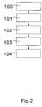
- Fig. 2 shows a method for authenticating a security element, with the steps of providing 100 at least one request signal from a verification point to a terminal by means of a network and reading 101 of the provided request signal by the security element and generating 102 at least one response signal by the security element using the at least one provided a request signal. Furthermore, the generated at least one response signal is transmitted 103 from the security element to the verification point for comparing 104 the at least one response signal with a stored response signal.
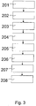
- Fig. 3 shows a schematic flow diagram according to an aspect of the present invention.
- a first method step 201 online authentication of a bank customer is initialized via an optical channel.
- the verification body sends e.g. B. a bank, a signal on the monitor of a person to be verified, for. B. the customer, is displayed, which is referred to herein as method step 202.
- a subsequent step 203 the person holds their ID document to the monitor on the displayed signal, e.g. B. a blinking area.
- the verification body transmits a code which is displayed on the monitor and is received by the security element by means of photodiodes. The received code is then processed by the security element into a new code in a method step 205. The new code is displayed by the LEDs of the ID and by the camera, e.g. B. the monitor, recorded and transmitted to the verification body, which is referred to as method step 206 in the present case.
- the verification body recognizes this new code and can automatically check the authenticity of the security element or the value document.
- the verification body checks the identity of the customer by means of camera recordings of the customer's face. This can be done optionally, but can also be done in parallel with the above-mentioned method steps.
- the advantage here is that, in addition to checking the customer's face for identification, the verification body can automatically check the ID or the security element in parallel and the customer can thus authenticate himself.
Landscapes
- Engineering & Computer Science (AREA)
- Computer Security & Cryptography (AREA)
- General Engineering & Computer Science (AREA)
- Computer Hardware Design (AREA)
- Signal Processing (AREA)
- Computer Networks & Wireless Communication (AREA)
- Computing Systems (AREA)
- Theoretical Computer Science (AREA)
- Power Engineering (AREA)
- Software Systems (AREA)
- Physics & Mathematics (AREA)
- General Physics & Mathematics (AREA)
- Collating Specific Patterns (AREA)
- Studio Devices (AREA)
Claims (8)
- Procédé d'authentification d'un élément de sécurité, comprenant les étapes :- mise à disposition (100) d'au moins un signal de demande d'un poste de vérification (VS) à un terminal au moyen d'un réseau ;- lecture (101), par l'élément de sécurité, du signal de demande mis à disposition, et génération (102) d'au moins un signal de réponse par l'élément de sécurité en utilisant le au moins un signal de demande mis à disposition ; et- transmission (103), de l'élément de sécurité au poste de vérification (VS), du au moins un signal de réponse généré pour la comparaison (104) du au moins un signal de réponse avec un signal de réponse mémorisé,caractérisé en ce que, en cas de concordance entre le au moins un signal de réponse transmis et un signal de réponse mémorisé, une authentification positive a lieu,
cependant que le signal de demande est lu par l'élément de sécurité par procédé d'imagerie,
cependant que le signal de demande présente une position d'écran à laquelle le signal de demande est affiché,
cependant que le signal de réponse est mis à disposition par l'élément de sécurité au moyen d'au moins une LED,
cependant que le signal de réponse de l'élément de sécurité est mis à la disposition d'une caméra, cependant que la caméra transfère le signal de réponse au poste de vérification au moyen d'une connexion Internet. - Procédé selon une des revendications précédentes, caractérisé en ce que le signal de demande décrit un code, un motif, un motif clignotant, des données alphanumériques, un symbole, un code QR et/ou un code-barres.
- Procédé selon une des revendications précédentes, caractérisé en ce que le signal de demande est lu par l'élément de sécurité en utilisant une photodiode.
- Procédé selon une des revendications précédentes, caractérisé en ce que les étapes du procédé sont exécutées au moins partiellement de manière différée.
- Procédé selon une des revendications précédentes, caractérisé en ce que le signal de réponse décrit un code, un motif, un motif clignotant, des données alphanumériques, un symbole, un code QR et/ou un code-barres.
- Procédé selon une des revendications précédentes, caractérisé en ce qu'une énergie est mise à la disposition de l'élément de sécurité au moyen de l'utilisation d'éléments photovoltaïques.
- Agencement d'authentification, destiné à l'authentification d'un élément de sécurité selon les revendications de 1 à 6, comprenant :- une unité d'interface conçue pour la mise à disposition (100) d'au moins un signal de demande d'un poste de vérification (VS) à un terminal au moyen d'un réseau ;- une unité de capteur conçue pour la lecture (101), par l'élément de sécurité, du signal de demande mis à disposition, et une unité de calcul conçue pour la génération (102), par l'élément de sécurité, d'au moins un signal de réponse en utilisant le au moins un signal de demande mis à disposition ; et- une autre unité d'interface conçue pour la transmission (103), de l'élément de sécurité au poste de vérification (VS), du au moins un signal de réponse généré pour la comparaison (104) du au moins un signal de réponse avec un signal de réponse mémorisé.
- Produit programme d'ordinateur ayant des instructions de commande qui mettent en œuvre le procédé selon une des revendications de 1 à 6.
Applications Claiming Priority (1)
| Application Number | Priority Date | Filing Date | Title |
|---|---|---|---|
| DE102016009258.0A DE102016009258A1 (de) | 2016-07-29 | 2016-07-29 | Authentisierungsanordnung |
Publications (2)
| Publication Number | Publication Date |
|---|---|
| EP3276909A1 EP3276909A1 (fr) | 2018-01-31 |
| EP3276909B1 true EP3276909B1 (fr) | 2020-03-25 |
Family
ID=59485118
Family Applications (1)
| Application Number | Title | Priority Date | Filing Date |
|---|---|---|---|
| EP17001286.8A Active EP3276909B1 (fr) | 2016-07-29 | 2017-07-26 | Dispositif d'authentification |
Country Status (2)
| Country | Link |
|---|---|
| EP (1) | EP3276909B1 (fr) |
| DE (1) | DE102016009258A1 (fr) |
Family Cites Families (10)
| Publication number | Priority date | Publication date | Assignee | Title |
|---|---|---|---|---|
| US5777903A (en) * | 1996-01-22 | 1998-07-07 | Motorola, Inc. | Solar cell powered smart card with integrated display and interface keypad |
| EP1333406A1 (fr) | 2002-02-04 | 2003-08-06 | Siemens Aktiengesellschaft | Authentification avec une tonalité d'appel |
| DE102008046339A1 (de) | 2008-09-09 | 2010-03-11 | Giesecke & Devrient Gmbh | Freigabe von Transaktionsdaten |
| WO2012116045A1 (fr) | 2011-02-25 | 2012-08-30 | Vasco Data Security, Inc. | Puissant jeton d'authentification comportant une entrée de données acoustique |
| PL2559563T3 (pl) | 2011-08-18 | 2014-10-31 | Polska Wytwornia Papierow Wartosciowych S A | Dokument zabezpieczony z efektem przeziernym i sposoby jego wytwarzania i weryfikacji |
| US20130204786A1 (en) * | 2012-02-03 | 2013-08-08 | Daniel Mattes | Verification of Online Transactions |
| DE102013201027A1 (de) * | 2013-01-23 | 2014-07-24 | Bundesdruckerei Gmbh | Verfahren zur Authentisierung eines Nutzers gegenüber einem Automat |
| DE102013108713B8 (de) * | 2013-08-12 | 2016-10-13 | WebID Solutions GmbH | Verfahren zum Verifizieren der ldentität eines Nutzers |
| US20150082390A1 (en) * | 2013-09-08 | 2015-03-19 | Yona Flink | Method and a system for secure login to a computer, computer network, and computer website using biometrics and a mobile computing wireless electronic communication device |
| DE102014018861A1 (de) * | 2014-12-16 | 2016-06-16 | Giesecke & Devrient Gmbh | Merkmal zur Identifikation mittels Webcam |
-
2016
- 2016-07-29 DE DE102016009258.0A patent/DE102016009258A1/de not_active Withdrawn
-
2017
- 2017-07-26 EP EP17001286.8A patent/EP3276909B1/fr active Active
Non-Patent Citations (1)
| Title |
|---|
| None * |
Also Published As
| Publication number | Publication date |
|---|---|
| EP3276909A1 (fr) | 2018-01-31 |
| DE102016009258A1 (de) | 2018-02-01 |
Similar Documents
| Publication | Publication Date | Title |
|---|---|---|
| DE69830306T2 (de) | Vorrichtung zur sicherheitsprüfung | |
| DE10224209B4 (de) | Autorisierungseinrichtung-Sicherheitsmodul-Terminal-System | |
| EP2948891B2 (fr) | Identification de l'utilisateur | |
| EP3327679B1 (fr) | Procédé de contrôle d'accès d'un groupe de personnes au moyen de plusieurs appareils de lecture et de plusieurs jetons | |
| DE102014109682A1 (de) | Mobiles Terminal zum Erfassen biometrischer Daten | |
| WO2014114476A1 (fr) | Procédé d'authentification d'un usager vis-à-vis d'un distributeur automatique | |
| EP2751950A1 (fr) | Procédé de génération d'un jeton logiciel, produit-programme d'ordinateur et système informatique de service | |
| DE102007050024A1 (de) | Personenkontrollsystem und Verfahren zum Durchführen einer Personenkontrolle | |
| EP3422243B1 (fr) | Token d'identification au microcontrôleur securisé | |
| EP3889807B1 (fr) | Système d'authentification basé sur un appareil de télécommunication doté d'un capteur d'activité cérébrale | |
| EP1697820B1 (fr) | Procede pour activer un acces a un systeme informatique ou a un programme | |
| EP3276909B1 (fr) | Dispositif d'authentification | |
| EP3404570A1 (fr) | Procédé et système d'authentification comportementale | |
| EP2364491A1 (fr) | Caractéristique d'identification | |
| EP3518190A1 (fr) | Procédé et dispositif d'authentification à facteurs multiples | |
| EP3510515B1 (fr) | Lunettes intelligentes permettant la signature cryptographique de données d'image | |
| DE102017220545A1 (de) | Verhaltensbasierte Authentifizierung mit Rückfallposition | |
| DE102015220244A1 (de) | Verfahren zur Überprüfung eines Dokumentes, Dokument und Computersystem | |
| DE102007012966A1 (de) | Verfahren zur Authentifizierung einer Person gegenüber einer Kontrolleinrichtung und gegenüber einem Gerät | |
| DE102019121321A1 (de) | Elektronische inhalationsvorrichtung, system, mundstück für eine elektronische inhalationsvorrichtung und authentifizierungsverfahren für eine inhalationsvorrichtung | |
| DE102019109343A1 (de) | Verfahren und Vorrichtung zur Übertragung digitaler Daten | |
| EP2154656A2 (fr) | Photogène | |
| WO2025132863A1 (fr) | Procédé d'enregistrement de données biométriques dans un support de données ayant un capteur biométrique | |
| DE102022116347A1 (de) | Hintergrundsystem für ein Personentransportsystem | |
| WO2015140046A1 (fr) | Procédé d'identification d'un utilisateur d'un appareil de communication à l'aide d'un service d'identification électronique |
Legal Events
| Date | Code | Title | Description |
|---|---|---|---|
| PUAI | Public reference made under article 153(3) epc to a published international application that has entered the european phase |
Free format text: ORIGINAL CODE: 0009012 |
|
| STAA | Information on the status of an ep patent application or granted ep patent |
Free format text: STATUS: THE APPLICATION HAS BEEN PUBLISHED |
|
| AK | Designated contracting states |
Kind code of ref document: A1 Designated state(s): AL AT BE BG CH CY CZ DE DK EE ES FI FR GB GR HR HU IE IS IT LI LT LU LV MC MK MT NL NO PL PT RO RS SE SI SK SM TR |
|
| AX | Request for extension of the european patent |
Extension state: BA ME |
|
| STAA | Information on the status of an ep patent application or granted ep patent |
Free format text: STATUS: REQUEST FOR EXAMINATION WAS MADE |
|
| 17P | Request for examination filed |
Effective date: 20180731 |
|
| RBV | Designated contracting states (corrected) |
Designated state(s): AL AT BE BG CH CY CZ DE DK EE ES FI FR GB GR HR HU IE IS IT LI LT LU LV MC MK MT NL NO PL PT RO RS SE SI SK SM TR |
|
| STAA | Information on the status of an ep patent application or granted ep patent |
Free format text: STATUS: EXAMINATION IS IN PROGRESS |
|
| 17Q | First examination report despatched |
Effective date: 20180906 |
|
| GRAP | Despatch of communication of intention to grant a patent |
Free format text: ORIGINAL CODE: EPIDOSNIGR1 |
|
| STAA | Information on the status of an ep patent application or granted ep patent |
Free format text: STATUS: GRANT OF PATENT IS INTENDED |
|
| INTG | Intention to grant announced |
Effective date: 20191105 |
|
| GRAS | Grant fee paid |
Free format text: ORIGINAL CODE: EPIDOSNIGR3 |
|
| GRAA | (expected) grant |
Free format text: ORIGINAL CODE: 0009210 |
|
| STAA | Information on the status of an ep patent application or granted ep patent |
Free format text: STATUS: THE PATENT HAS BEEN GRANTED |
|
| AK | Designated contracting states |
Kind code of ref document: B1 Designated state(s): AL AT BE BG CH CY CZ DE DK EE ES FI FR GB GR HR HU IE IS IT LI LT LU LV MC MK MT NL NO PL PT RO RS SE SI SK SM TR |
|
| REG | Reference to a national code |
Ref country code: GB Ref legal event code: FG4D Free format text: NOT ENGLISH |
|
| REG | Reference to a national code |
Ref country code: AT Ref legal event code: REF Ref document number: 1249898 Country of ref document: AT Kind code of ref document: T Effective date: 20200415 Ref country code: IE Ref legal event code: FG4D Free format text: LANGUAGE OF EP DOCUMENT: GERMAN |
|
| REG | Reference to a national code |
Ref country code: DE Ref legal event code: R096 Ref document number: 502017004329 Country of ref document: DE |
|
| PG25 | Lapsed in a contracting state [announced via postgrant information from national office to epo] |
Ref country code: NO Free format text: LAPSE BECAUSE OF FAILURE TO SUBMIT A TRANSLATION OF THE DESCRIPTION OR TO PAY THE FEE WITHIN THE PRESCRIBED TIME-LIMIT Effective date: 20200625 Ref country code: RS Free format text: LAPSE BECAUSE OF FAILURE TO SUBMIT A TRANSLATION OF THE DESCRIPTION OR TO PAY THE FEE WITHIN THE PRESCRIBED TIME-LIMIT Effective date: 20200325 Ref country code: FI Free format text: LAPSE BECAUSE OF FAILURE TO SUBMIT A TRANSLATION OF THE DESCRIPTION OR TO PAY THE FEE WITHIN THE PRESCRIBED TIME-LIMIT Effective date: 20200325 |
|
| PG25 | Lapsed in a contracting state [announced via postgrant information from national office to epo] |
Ref country code: HR Free format text: LAPSE BECAUSE OF FAILURE TO SUBMIT A TRANSLATION OF THE DESCRIPTION OR TO PAY THE FEE WITHIN THE PRESCRIBED TIME-LIMIT Effective date: 20200325 Ref country code: GR Free format text: LAPSE BECAUSE OF FAILURE TO SUBMIT A TRANSLATION OF THE DESCRIPTION OR TO PAY THE FEE WITHIN THE PRESCRIBED TIME-LIMIT Effective date: 20200626 Ref country code: LV Free format text: LAPSE BECAUSE OF FAILURE TO SUBMIT A TRANSLATION OF THE DESCRIPTION OR TO PAY THE FEE WITHIN THE PRESCRIBED TIME-LIMIT Effective date: 20200325 Ref country code: SE Free format text: LAPSE BECAUSE OF FAILURE TO SUBMIT A TRANSLATION OF THE DESCRIPTION OR TO PAY THE FEE WITHIN THE PRESCRIBED TIME-LIMIT Effective date: 20200325 Ref country code: BG Free format text: LAPSE BECAUSE OF FAILURE TO SUBMIT A TRANSLATION OF THE DESCRIPTION OR TO PAY THE FEE WITHIN THE PRESCRIBED TIME-LIMIT Effective date: 20200625 |
|
| REG | Reference to a national code |
Ref country code: NL Ref legal event code: MP Effective date: 20200325 |
|
| REG | Reference to a national code |
Ref country code: LT Ref legal event code: MG4D |
|
| PG25 | Lapsed in a contracting state [announced via postgrant information from national office to epo] |
Ref country code: NL Free format text: LAPSE BECAUSE OF FAILURE TO SUBMIT A TRANSLATION OF THE DESCRIPTION OR TO PAY THE FEE WITHIN THE PRESCRIBED TIME-LIMIT Effective date: 20200325 |
|
| PG25 | Lapsed in a contracting state [announced via postgrant information from national office to epo] |
Ref country code: CZ Free format text: LAPSE BECAUSE OF FAILURE TO SUBMIT A TRANSLATION OF THE DESCRIPTION OR TO PAY THE FEE WITHIN THE PRESCRIBED TIME-LIMIT Effective date: 20200325 Ref country code: RO Free format text: LAPSE BECAUSE OF FAILURE TO SUBMIT A TRANSLATION OF THE DESCRIPTION OR TO PAY THE FEE WITHIN THE PRESCRIBED TIME-LIMIT Effective date: 20200325 Ref country code: SM Free format text: LAPSE BECAUSE OF FAILURE TO SUBMIT A TRANSLATION OF THE DESCRIPTION OR TO PAY THE FEE WITHIN THE PRESCRIBED TIME-LIMIT Effective date: 20200325 Ref country code: EE Free format text: LAPSE BECAUSE OF FAILURE TO SUBMIT A TRANSLATION OF THE DESCRIPTION OR TO PAY THE FEE WITHIN THE PRESCRIBED TIME-LIMIT Effective date: 20200325 Ref country code: LT Free format text: LAPSE BECAUSE OF FAILURE TO SUBMIT A TRANSLATION OF THE DESCRIPTION OR TO PAY THE FEE WITHIN THE PRESCRIBED TIME-LIMIT Effective date: 20200325 Ref country code: PT Free format text: LAPSE BECAUSE OF FAILURE TO SUBMIT A TRANSLATION OF THE DESCRIPTION OR TO PAY THE FEE WITHIN THE PRESCRIBED TIME-LIMIT Effective date: 20200818 Ref country code: SK Free format text: LAPSE BECAUSE OF FAILURE TO SUBMIT A TRANSLATION OF THE DESCRIPTION OR TO PAY THE FEE WITHIN THE PRESCRIBED TIME-LIMIT Effective date: 20200325 Ref country code: IS Free format text: LAPSE BECAUSE OF FAILURE TO SUBMIT A TRANSLATION OF THE DESCRIPTION OR TO PAY THE FEE WITHIN THE PRESCRIBED TIME-LIMIT Effective date: 20200725 |
|
| REG | Reference to a national code |
Ref country code: DE Ref legal event code: R097 Ref document number: 502017004329 Country of ref document: DE |
|
| PG25 | Lapsed in a contracting state [announced via postgrant information from national office to epo] |
Ref country code: DK Free format text: LAPSE BECAUSE OF FAILURE TO SUBMIT A TRANSLATION OF THE DESCRIPTION OR TO PAY THE FEE WITHIN THE PRESCRIBED TIME-LIMIT Effective date: 20200325 Ref country code: IT Free format text: LAPSE BECAUSE OF FAILURE TO SUBMIT A TRANSLATION OF THE DESCRIPTION OR TO PAY THE FEE WITHIN THE PRESCRIBED TIME-LIMIT Effective date: 20200325 Ref country code: ES Free format text: LAPSE BECAUSE OF FAILURE TO SUBMIT A TRANSLATION OF THE DESCRIPTION OR TO PAY THE FEE WITHIN THE PRESCRIBED TIME-LIMIT Effective date: 20200325 |
|
| PLBE | No opposition filed within time limit |
Free format text: ORIGINAL CODE: 0009261 |
|
| STAA | Information on the status of an ep patent application or granted ep patent |
Free format text: STATUS: NO OPPOSITION FILED WITHIN TIME LIMIT |
|
| PG25 | Lapsed in a contracting state [announced via postgrant information from national office to epo] |
Ref country code: PL Free format text: LAPSE BECAUSE OF FAILURE TO SUBMIT A TRANSLATION OF THE DESCRIPTION OR TO PAY THE FEE WITHIN THE PRESCRIBED TIME-LIMIT Effective date: 20200325 Ref country code: MC Free format text: LAPSE BECAUSE OF FAILURE TO SUBMIT A TRANSLATION OF THE DESCRIPTION OR TO PAY THE FEE WITHIN THE PRESCRIBED TIME-LIMIT Effective date: 20200325 |
|
| REG | Reference to a national code |
Ref country code: CH Ref legal event code: PL |
|
| 26N | No opposition filed |
Effective date: 20210112 |
|
| REG | Reference to a national code |
Ref country code: BE Ref legal event code: MM Effective date: 20200731 |
|
| PG25 | Lapsed in a contracting state [announced via postgrant information from national office to epo] |
Ref country code: CH Free format text: LAPSE BECAUSE OF NON-PAYMENT OF DUE FEES Effective date: 20200731 Ref country code: LI Free format text: LAPSE BECAUSE OF NON-PAYMENT OF DUE FEES Effective date: 20200731 Ref country code: LU Free format text: LAPSE BECAUSE OF NON-PAYMENT OF DUE FEES Effective date: 20200726 |
|
| PG25 | Lapsed in a contracting state [announced via postgrant information from national office to epo] |
Ref country code: BE Free format text: LAPSE BECAUSE OF NON-PAYMENT OF DUE FEES Effective date: 20200731 Ref country code: SI Free format text: LAPSE BECAUSE OF FAILURE TO SUBMIT A TRANSLATION OF THE DESCRIPTION OR TO PAY THE FEE WITHIN THE PRESCRIBED TIME-LIMIT Effective date: 20200325 |
|
| PG25 | Lapsed in a contracting state [announced via postgrant information from national office to epo] |
Ref country code: IE Free format text: LAPSE BECAUSE OF NON-PAYMENT OF DUE FEES Effective date: 20200726 |
|
| REG | Reference to a national code |
Ref country code: DE Ref legal event code: R079 Ref document number: 502017004329 Country of ref document: DE Free format text: PREVIOUS MAIN CLASS: H04L0029060000 Ipc: H04L0065000000 |
|
| PG25 | Lapsed in a contracting state [announced via postgrant information from national office to epo] |
Ref country code: TR Free format text: LAPSE BECAUSE OF FAILURE TO SUBMIT A TRANSLATION OF THE DESCRIPTION OR TO PAY THE FEE WITHIN THE PRESCRIBED TIME-LIMIT Effective date: 20200325 Ref country code: MT Free format text: LAPSE BECAUSE OF FAILURE TO SUBMIT A TRANSLATION OF THE DESCRIPTION OR TO PAY THE FEE WITHIN THE PRESCRIBED TIME-LIMIT Effective date: 20200325 Ref country code: CY Free format text: LAPSE BECAUSE OF FAILURE TO SUBMIT A TRANSLATION OF THE DESCRIPTION OR TO PAY THE FEE WITHIN THE PRESCRIBED TIME-LIMIT Effective date: 20200325 |
|
| PG25 | Lapsed in a contracting state [announced via postgrant information from national office to epo] |
Ref country code: MK Free format text: LAPSE BECAUSE OF FAILURE TO SUBMIT A TRANSLATION OF THE DESCRIPTION OR TO PAY THE FEE WITHIN THE PRESCRIBED TIME-LIMIT Effective date: 20200325 Ref country code: AL Free format text: LAPSE BECAUSE OF FAILURE TO SUBMIT A TRANSLATION OF THE DESCRIPTION OR TO PAY THE FEE WITHIN THE PRESCRIBED TIME-LIMIT Effective date: 20200325 |
|
| P01 | Opt-out of the competence of the unified patent court (upc) registered |
Effective date: 20230520 |
|
| REG | Reference to a national code |
Ref country code: DE Ref legal event code: R081 Ref document number: 502017004329 Country of ref document: DE Owner name: GIESECKE+DEVRIENT EPAYMENTS GMBH, DE Free format text: FORMER OWNER: GIESECKE+DEVRIENT MOBILE SECURITY GMBH, 81677 MUENCHEN, DE |
|
| REG | Reference to a national code |
Ref country code: AT Ref legal event code: MM01 Ref document number: 1249898 Country of ref document: AT Kind code of ref document: T Effective date: 20220726 |
|
| PG25 | Lapsed in a contracting state [announced via postgrant information from national office to epo] |
Ref country code: AT Free format text: LAPSE BECAUSE OF NON-PAYMENT OF DUE FEES Effective date: 20220726 |
|
| PGFP | Annual fee paid to national office [announced via postgrant information from national office to epo] |
Ref country code: DE Payment date: 20240731 Year of fee payment: 8 |
|
| PGFP | Annual fee paid to national office [announced via postgrant information from national office to epo] |
Ref country code: GB Payment date: 20240723 Year of fee payment: 8 |
|
| PGFP | Annual fee paid to national office [announced via postgrant information from national office to epo] |
Ref country code: FR Payment date: 20240724 Year of fee payment: 8 |
|
| REG | Reference to a national code |
Ref country code: DE Ref legal event code: R119 Ref document number: 502017004329 Country of ref document: DE |
|
| GBPC | Gb: european patent ceased through non-payment of renewal fee |
Effective date: 20250726 |
|
| PG25 | Lapsed in a contracting state [announced via postgrant information from national office to epo] |
Ref country code: GB Free format text: LAPSE BECAUSE OF NON-PAYMENT OF DUE FEES Effective date: 20250726 |
|
| PG25 | Lapsed in a contracting state [announced via postgrant information from national office to epo] |
Ref country code: DE Free format text: LAPSE BECAUSE OF NON-PAYMENT OF DUE FEES Effective date: 20260203 |
|
| PG25 | Lapsed in a contracting state [announced via postgrant information from national office to epo] |
Ref country code: FR Free format text: LAPSE BECAUSE OF NON-PAYMENT OF DUE FEES Effective date: 20250731 |