EP3277559B1 - Fahrzeugstruktur mit zwei kraftkanälen mit verbessertem verhalten und fahrzeug mit solch einer struktur - Google Patents
Fahrzeugstruktur mit zwei kraftkanälen mit verbessertem verhalten und fahrzeug mit solch einer struktur Download PDFInfo
- Publication number
- EP3277559B1 EP3277559B1 EP16707908.6A EP16707908A EP3277559B1 EP 3277559 B1 EP3277559 B1 EP 3277559B1 EP 16707908 A EP16707908 A EP 16707908A EP 3277559 B1 EP3277559 B1 EP 3277559B1
- Authority
- EP
- European Patent Office
- Prior art keywords
- reinforcing element
- vehicle
- mudguard
- structure according
- connection means
- Prior art date
- Legal status (The legal status is an assumption and is not a legal conclusion. Google has not performed a legal analysis and makes no representation as to the accuracy of the status listed.)
- Active
Links
Images


Classifications
-
- B—PERFORMING OPERATIONS; TRANSPORTING
- B62—LAND VEHICLES FOR TRAVELLING OTHERWISE THAN ON RAILS
- B62D—MOTOR VEHICLES; TRAILERS
- B62D25/00—Superstructure or monocoque structure sub-units; Parts or details thereof not otherwise provided for
- B62D25/08—Front or rear portions
-
- B—PERFORMING OPERATIONS; TRANSPORTING
- B62—LAND VEHICLES FOR TRAVELLING OTHERWISE THAN ON RAILS
- B62D—MOTOR VEHICLES; TRAILERS
- B62D21/00—Understructures, i.e. chassis frame on which a vehicle body may be mounted
- B62D21/15—Understructures, i.e. chassis frame on which a vehicle body may be mounted having impact absorbing means, e.g. a frame designed to permanently or temporarily change shape or dimension upon impact with another body
- B62D21/152—Front or rear frames
Definitions
- the present invention relates to a vehicle structure having a first reinforcing member and a second reinforcing member.
- the first reinforcing member is adapted to transmit a large part of the forces due to impact along a main direction of work, forming a main path of effort.
- the second reinforcing element is adapted to transmit the remainder of the forces due to this impact along said main working direction, forming a secondary force path.
- the second reinforcing element thus constitutes force recovery means of the first reinforcing element.
- the figure 1 represents a partial view of the front part of the structure of a vehicle as known from the state of the art.
- the front structure comprises a first reinforcing element 1 and a second reinforcing element 2.
- the front structure comprises a front cross member 3 positioned just behind the front bumper skin (the bumper skin is not shown ) and which forms a support for a radiator 4.
- the front cross member 3 also forms a rigid connecting element between the first reinforcing element 1 and the second reinforcing element 2.
- the first reinforcing element 1 forms a main effort channel for damping and transmitting to another part of the vehicle structure a first part of the energy resulting from a shock on the front of the vehicle.
- the first reinforcing element 1 extends mainly along a main working direction corresponding to the direction of movement of the vehicle during the front impact.
- the second reinforcing element 2 forms a secondary force path for damping and transmitting a second part of the energy resulting from the impact along the same main working direction.
- the second reinforcing element 2 extends mainly in the main direction of work, parallel to the first reinforcing element 1.
- the first reinforcing element 1 comprises a first part 11, positioned furthest in front of the vehicle, which is adapted to dampen the energy resulting from the shock by compressing a maximum once a first level of effort applied to the front of the vehicle.
- the first part 11 of the first reinforcing element 1 is generally called "crash box".
- the first reinforcing element 1 comprises, in the extension of the first portion 11, a second portion 12 which is adapted to deform once a second level of force applied to the front of the vehicle.
- the first reinforcing element 1 comprises, in the extension of the second part 12, a third part 13 which is adapted, once the two thresholds of forces are exceeded, to transmit the excess of energy to be damped to the rest of the structure of the vehicle.
- the third part 13 of the first reinforcing element 1 also forms part of the cradle of the engine 5 and is in particular commonly called a spoiler.
- the engine 5 is essentially positioned between the two longitudinal members 13.
- the rear portion of the longitudinal members 13 is secured to an apron 6, which forms a separation between the passenger compartment of the vehicle and the engine compartment 5.
- the longitudinal members 13 are extended by the longitudinal members 7 which serve to stiffen the central structure of the vehicle.
- the first portion 11 and the second portion 12 of the first reinforcing member 1 are sized so that on a low speed shock, only the first portion 11 is deformed.
- the first part 11 of the first reinforcing element 1 is simple to replace, making it possible to limit the parts to be replaced during such a shock at low speed.
- the second reinforcing element 2 comprises a first part 21, positioned below the first reinforcing element 1, which is adapted to crash substantially at the same time as the first part 11 of the first reinforcing element 1.
- the second reinforcing element 2 comprises, in the extension of the first portion 21, a second linear portion 22 intended to absorb a portion of the energy resulting from the impact by a bending of its central portion 23. Such bending of the central portion 23 corresponds to a buckling of the second portion 22 of the second reinforcing element 2.
- the rear end of the second portion 22 of the second reinforcing element 2 is secured to a portion of the front axle of the vehicle which forms the lower suspension cradle 8.
- the two parts of the second reinforcing element 2 may be deformed, but such a deformation is there to protect the lower cradle 8 which will not be have been damaged during such a low-speed shock.
- the second element of reinforcement 2 has no structural role for the front of the vehicle, it can be easily replaced.
- the figure 2 represents the front part of the vehicle structure after an impact as realized by the European New Car Assessment Program, better known under the abbreviation "Euro NCAP”, which consists in impacting a vehicle launched at 64 km / h against a wall 9 which has the particularity of having a protrusion 91 in the lower part.
- Euro NCAP European New Car Assessment Program
- a vehicle of the "SUV” type an acronym for "Sport Utility Vehicle”, generally comprising a raised structure compared to a sedan-type motor vehicle, the protruding part 91 of the wall 9 is only opposite the second reinforcing element.
- the second reinforcing element 2 undergoes stresses greater than the first reinforcing element 1, causing the central portion 23 of the second portion 22 of the second reinforcing element 2 to bend when such a shock beyond its limit of resistance.
- the central portion 23 of the second reinforcing element then has a plastic deformation, so that the second reinforcing element 2 no longer has buckling resistance during impact.
- the amplitude of the deformation of the second portion 22 of the second element 2 may then create a rupture of a hinge 24 which connects the second reinforcing element 2 to the lower cradle 8.
- the second reinforcing element 2 also leads downwards the front cross member 3 and therefore the front end of the second portion 12 of the first reinforcing member 1.
- One of the aims of the invention is therefore to at least partially overcome the drawbacks of the prior art and to propose a vehicle structure which comprises a first reinforcing element and such a second reinforcing element and which is suitable for, when impact against a wall with such asymmetry, maintain good structural alignment to the first and second reinforcement elements.
- a vehicle structure which comprises a first reinforcing element and such a second reinforcing element and which is suitable for, when impact against a wall with such asymmetry, maintain good structural alignment to the first and second reinforcement elements.
- a vehicle structure comprising a first reinforcing element and a second reinforcing element, the first reinforcing element being adapted to transmit a large part of the forces due to impact in a main direction of work, forming a main path of effort, the second reinforcing element being adapted to transmit the remainder of the forces due to the impact along said main working direction, forming a secondary force path, such that elastic connecting means connect the first element of reinforcement to the second reinforcing element.
- the second reinforcement element comprises a linear part intended to absorb a part of the energy due to impact by a bending of its central part
- the elastic connection means comprise a first end integral with said central part
- the first reinforcing element comprises, in the same extension along said main working direction, at least a first part intended to crash during said impact and another part forming a side member, a second part end of the elastic connection means being integral with said side member.
- At least a portion of the elastic connection means is formed by a cable.
- the cable to withstand shock without breaking usually has a breaking load of at least 3400kg.
- the structure comprises a mudguard intended to at least partially cover a wheel of the vehicle, a portion of the mudguard being secured to the first structural member and the second structural member so as to forming said elastic connection means.
- the mudguard is made of a plastic material, at least a portion of the elastic connection means being formed directly in the mudguard.
- the elastic connection means form a ramp locally modifying the stiffness of the mudguard, a first end of the shoulder strap being integral with the first structural element, the second end being integral with the second structural element.
- the strap comprises a first hollow linear portion formed in the mudguard and a second linear portion attached to be positioned in said first portion of the ramp.
- the strap is formed by an extra thickness of the mudguard.
- a plastic or metal core can be inserted into said extra thickness during the manufacture by molding the mudguard.
- the present invention also relates to a vehicle comprising a structure which comprises at least one of the preceding characteristics.
- FIGS. 3 to 5 represent partial views of the front part of the vehicle structure according to the invention, during the different phases of a front impact against a wall 9 of the asymmetrical type, which has an outgrowth 91 in the lower part.
- a wall 9 of the asymmetrical type which has an outgrowth 91 in the lower part.
- Such an asymmetrical wall 9 corresponds to one of the forward shock tests practiced by the "Euro NCAP" body, as explained previously.
- elastic connection means 100 connect the third portion 13 of the first reinforcing member 1 at the second portion 22 of the second reinforcing member 2, preferably near the central portion 23 of the second portion 22 of the second reinforcing member 2.
- FIG. 4 On the figure 4 is represented a first phase of the shock before the first part 11 of the first reinforcing element 1 is compressed following contact against the protruding portion 91 of the wall 9.
- the second reinforcing element 2 which is first requested because of the presence of the protruding portion 91, has both a crushing of the first portion 21 and a deformation of the second portion 22.
- the second portion 22 of the second reinforcing member 2 begins to flex, curving at its portion 23. The curvature is for the moment of low amplitude so that the elastic connection means 100 are not yet solicited.
- This asymmetry in the front shock has the effect of slightly tilting forward the front crossbar 3.
- FIG. 5 On the figure 5 is represented a second phase of the shock before where the first reinforcing element 1 is in turn solicited.
- the second reinforcing element 2 which is always more stressed because of the presence of the protruding portion 91, has a strong deflection in the central portion 23 of the second portion 22.
- the elastic connecting means 100 limit the deflection of the second part 22 of the second reinforcing element 2, thus avoiding reaching the limit of elastic deformation of the second part 22 of the second reinforcing element 2 and the resilient connection means 100 also make it possible to limit the forward tilting of the front cross member 3, making it possible to keep the second part 12 and the third part 13 of the first element substantially aligned; reinforcement 1, retaining all these capabilities of impact resistance.
- the elastic connection means may be formed by a metal cable.
- a metal cable is constituted by a 19-wire cable, which has a total diameter of 6 mm for a weight of 180 g with a break at the minimum load of 3400 kg.
- Such a cable is commonly found for the transmission of forces in the automotive environment as in the production of parking brake transmission cables.
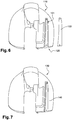
- the figure 6 represents a mudguard 110 which comprises a shoulder strap 120 which forms elastic connecting means according to a second embodiment of the invention.
- the shoulder strap 120 has a first portion 121 and a second portion 122.
- the first portion 121 of the shoulder strap 120 has a hollow elongated shape directly formed in the mudguard 110.
- the first portion 121 has a shape adapted to receive the second portion 122 which also has a corresponding elongate shape.
- At the two ends of the shoulder strap 120 are secured the third portion 13 of the first reinforcing member 3 and the second portion 22 of the second reinforcing member 2, as shown in the preceding figs.
- the shoulder strap 120 Due to the elasticity of the mudguard 100 which consists of a plastic material, the shoulder strap 120 thus forms elastic connecting means which make it possible to limit, as previously, the deflection in its central part 23 of the second part 22
- the second portion 122 of the shoulder strap 120 forms a reinforcing piece which makes it possible to adjust the stiffness of the shoulder strap 120.
- the second portion 122 of the shoulder strap 120 can be maintained in the first portion 121 of the strap 120 by gluing.
- a hot assembly can also be used.
- Such a shoulder strap 120 must allow the central portion 23 of the second portion 22 of the second reinforcing element 2 to be able to flex slightly during an impact without reaching a threshold value which would dangerously weaken the second reinforcing element 2 and consequently the first reinforcing element 1.
- the figure 7 represents a mudguard 130 which comprises a shoulder strap 140 which forms elastic connection means according to a third embodiment of the invention.
- the strap 140 has an elongated shape in excess of the mudguard 130.
- An insert, made of a material having characteristics of different stiffness, can be inserted into the strap 140 when the mudguard 130 is made.
- the strap 140 are secured to the third part 13 of the first reinforcing element 3 and the second part 22 of the second reinforcing element 2, as shown in FIGS. 1 to 5.
- the dimensioning of this extra thickness makes it possible to adjust the coefficient of stiffness of the shoulder strap 130 which makes it possible to condition the behavior of the second reinforcing element 2 and the first reinforcing element during the impact.
Landscapes
- Engineering & Computer Science (AREA)
- Chemical & Material Sciences (AREA)
- Combustion & Propulsion (AREA)
- Transportation (AREA)
- Mechanical Engineering (AREA)
- Body Structure For Vehicles (AREA)
Claims (10)
- Fahrzeugstruktur, die ein erstes Verstärkungselement (1) und ein zweites Verstärkungselement (2) umfasst, wobei das erste Verstärkungselement (1) angepasst ist, um einen großen Teil der Kräfte zu übertragen, die auf einen Stoß entlang einer Hauptarbeitsrichtung zurückzuführen sind, die einen Hauptkraftkanal bildet, übertragen werden, wobei das zweite Verstärkungselement (2) angepasst ist, um den Rest der Kräfte, die auf den Stoß zurückzuführen sind, entlang der Hauptarbeitsrichtung, die einen Sekundärkraftkanal bildet, zu übertragen, dadurch gekennzeichnet, das elastische Verbindungsmittel (100, 120, 140) das erste Verstärkungselement (1) mit dem zweiten Verstärkungselement (2) verbindet.
- Struktur nach Anspruch 1, dadurch gekennzeichnet, dass das zweite Verstärkungselement (2) einen linearen Teil (22) umfasst, der dazu bestimmt ist, einen Teil der Energie, die auf den Stoß zurückzuführen ist, durch eine Biegung seines zentralen Teils (23) zu absorbieren, wobei die elastischen Verbindungsmittel (100, 120, 140) ein erstes Ende, das fest mit dem zentralen Teil (23) verbunden ist, umfassen.
- Struktur nach Anspruch 1 oder 2, dadurch gekennzeichnet, dass das erste Verstärkungselement (1) in einer selben Verlängerung entlang der Hauptarbeitsrichtung mindestens einen ersten Teil (11) umfasst, der dazu bestimmt ist, bei dem Stoß zusammengedrückt zu werden, und einen anderen Teil, der einen Holm (13) bildet, wobei ein zweites Ende der elastischen Verbindungsmittel (100, 120, 140) fest mit dem Holm (13) verbunden ist.
- Struktur nach einem der vorstehenden Ansprüche, dadurch gekennzeichnet, dass mindestens ein Teil der elastischen Verbindungsmittel (100) von einem Kabel gebildet ist.
- Struktur nach Anspruch 4, dadurch gekennzeichnet, dass das Kabel (100) eine Bruchbelastung von mindestens 3400 kg aufweist.
- Struktur nach einem der Ansprüche 1 bis 3, dadurch gekennzeichnet, dass sie einen Kotflügel (110, 130) umfasst, der dazu bestimmt ist, ein Rad des Fahrzeugs mindestens teilweise abzudecken, wobei ein Teil (120, 140) des Kotflügels (110, 130) fest mit dem ersten Verstärkungselement (1) und dem zweiten Verstärkungselement (2) derart verbunden ist, dass er die elastischen Verbindungsmittel (120, 140) bildet.
- Struktur nach dem vorstehenden Anspruch, dadurch gekennzeichnet, dass der Kotflügel (110, 130) aus einem Kunststoff hergestellt ist, dass mindestens ein Teil der elastischen Verbindungsmittel (120, 140) direkt in dem Kotflügel (110, 130) gebildet ist.
- Struktur nach dem vorstehenden Anspruch, dadurch gekennzeichnet, dass die elastischen Verbindungsmittel einen Verbindungssteg (120, 140) bilden, der die Steifigkeit des Kotflügels (110, 130) lokal verändert, wobei ein erstes Ende des Verbindungsstegs (120) fest mit dem ersten Verstärkungselement (1) verbunden ist, wobei das zweite Ende fest mit dem zweiten Verstärkungselement (2) verbunden ist.
- Struktur nach dem vorstehenden Anspruch, dadurch gekennzeichnet, dass der Verbindungssteg (120) einen ersten linearen Teil (121), der in dem Kotflügel (110) gebildet ist, und einen zweiten angebauten linearen Teil (122), der dazu bestimmt ist, in dem ersten Teil (121) des Verbindungsstegs (120) positioniert zu sein, umfasst.
- Fahrzeug, das eine Struktur nach einem der vorstehenden Ansprüche umfasst.
Applications Claiming Priority (2)
| Application Number | Priority Date | Filing Date | Title |
|---|---|---|---|
| FR1551731A FR3033297B1 (fr) | 2015-03-02 | 2015-03-02 | Structure de vehicule comportant deux voies d’efforts a comportement ameliore et vehicule comportant une telle structure |
| PCT/FR2016/050321 WO2016139399A1 (fr) | 2015-03-02 | 2016-02-12 | Structure de vehicule comportant deux voies d'efforts a comportement ameliore et vehicule comportant une telle structure |
Publications (2)
| Publication Number | Publication Date |
|---|---|
| EP3277559A1 EP3277559A1 (de) | 2018-02-07 |
| EP3277559B1 true EP3277559B1 (de) | 2019-08-14 |
Family
ID=53514289
Family Applications (1)
| Application Number | Title | Priority Date | Filing Date |
|---|---|---|---|
| EP16707908.6A Active EP3277559B1 (de) | 2015-03-02 | 2016-02-12 | Fahrzeugstruktur mit zwei kraftkanälen mit verbessertem verhalten und fahrzeug mit solch einer struktur |
Country Status (4)
| Country | Link |
|---|---|
| EP (1) | EP3277559B1 (de) |
| CN (1) | CN107438554B (de) |
| FR (1) | FR3033297B1 (de) |
| WO (1) | WO2016139399A1 (de) |
Families Citing this family (1)
| Publication number | Priority date | Publication date | Assignee | Title |
|---|---|---|---|---|
| FR3100214B1 (fr) | 2019-08-27 | 2021-07-23 | Psa Automobiles Sa | Vehicule hybride ou electrique avec dispositif de renforcement de sa structure de bas de caisse |
Family Cites Families (7)
| Publication number | Priority date | Publication date | Assignee | Title |
|---|---|---|---|---|
| DE19953808B4 (de) * | 1999-11-09 | 2004-09-02 | Daimlerchrysler Ag | Vorbautragstruktur für eine selbsttragende Karosserie eines Kraftfahrzeugs |
| FR2813269B1 (fr) * | 2000-08-29 | 2002-11-01 | Renault | Ensemble de structure de caisse comportant des carenages lateraux |
| FR2824523B1 (fr) * | 2001-05-11 | 2003-10-10 | Peugeot Citroen Automobiles Sa | Structure de vehicule automobile a compotement ameliore au choc |
| US7896428B2 (en) * | 2005-01-28 | 2011-03-01 | Toyota Jidosha Kabushiki Kaisha | Vehicle body structure |
| DE102005034465B4 (de) * | 2005-07-23 | 2007-06-06 | Daimlerchrysler Ag | Lastkraftwagen mit Kollisionsrückhaltesystem für das Fahrerhaus |
| FR2896222B1 (fr) * | 2006-01-19 | 2009-07-17 | Peugeot Citroen Automobiles Sa | Module d'absorption de chocs pour une face avant d'un vehicule automobile et vehicule automobile comportant un tel module. |
| ITTO20130474A1 (it) * | 2013-06-07 | 2014-12-08 | Fiat Group Automobiles Spa | Autoveicolo provvisto di un sistema di sgancio per staccare una traversa nel vano motore in caso d'urto frontale |
-
2015
- 2015-03-02 FR FR1551731A patent/FR3033297B1/fr not_active Expired - Fee Related
-
2016
- 2016-02-12 WO PCT/FR2016/050321 patent/WO2016139399A1/fr not_active Ceased
- 2016-02-12 EP EP16707908.6A patent/EP3277559B1/de active Active
- 2016-02-12 CN CN201680013448.4A patent/CN107438554B/zh not_active Expired - Fee Related
Non-Patent Citations (1)
| Title |
|---|
| None * |
Also Published As
| Publication number | Publication date |
|---|---|
| CN107438554A (zh) | 2017-12-05 |
| FR3033297B1 (fr) | 2017-03-24 |
| WO2016139399A1 (fr) | 2016-09-09 |
| FR3033297A1 (fr) | 2016-09-09 |
| CN107438554B (zh) | 2020-07-28 |
| EP3277559A1 (de) | 2018-02-07 |
Similar Documents
| Publication | Publication Date | Title |
|---|---|---|
| EP1893469B1 (de) | Geführter unterbereich der front eines automobils | |
| EP2930067B1 (de) | Stossfängerträger für fahrzeug, stossfängeranordnung und entsprechendes fahrzeug | |
| WO2019115552A1 (fr) | Systeme d'absorption de choc pour vehicule automobile | |
| EP2910399B1 (de) | Pantograf für Schienenfahrzeug | |
| EP3277543B1 (de) | Fahrzeug mit leichtbaustruktur mit zwei blastungswege | |
| EP3277559B1 (de) | Fahrzeugstruktur mit zwei kraftkanälen mit verbessertem verhalten und fahrzeug mit solch einer struktur | |
| FR2864811A1 (fr) | Dispositif de protection contre les chocs pour un vehicule automobile | |
| FR3006979A1 (fr) | Agencement de carrosserie dote d'un agencement de protection pour pieces jouant un role au niveau de la securite dans le domaine des vehicules automobiles | |
| EP2983969B1 (de) | Aerodynamischer deflektor für den hinteren teil eines fahrzeugs | |
| EP2867097B1 (de) | Kraftfahrzeug mit einem zusatzbewehrungsteil zur anleitung der verformung der zentralen säulenstruktur bei einem seitenaufprall | |
| WO2017064611A1 (fr) | Composant de structure de véhicule automobile, et section de voie basse avant comprenant un tel composant | |
| EP3386783B1 (de) | Verfahren zur herstellung einer hinterachse eines kraftfahrzeugs durch aufschrumpfen eines querträgers in einem arm | |
| EP3676115B1 (de) | Fahrzeug mit einem hinteren radsatz mit gesteuerter längsverschiebung im falle eines heckaufpralls | |
| FR2871122A1 (fr) | Poutre de pare-chocs a moyens de montage d'un organe de remorquage et vehicule automobile correspondant | |
| EP1874592B1 (de) | Frontstruktur für ein kraftfahrzeug | |
| EP3986772B1 (de) | Fahrzeugflügel mit schmelzbarem bereich für programmierte verformung | |
| FR2958885A1 (fr) | Structure de vehicule automobile pour la fixation et la protection d'un module de refroidissement | |
| FR2982814A1 (fr) | Systeme de resistance aux chocs comprenant une piece de renfort. | |
| EP3286041B1 (de) | Klemme zur befestigung eines stossfängers an einer kraftfahrzeugkarosserie | |
| EP1762439A1 (de) | Kraftfahrzeug-Stossstangenträger | |
| FR2919246A3 (fr) | Element de carrosserie pre-amenage pour amortir un choc pieton | |
| FR2892681A1 (fr) | Structure de la partie avant d'un vehicule automobile comportant des moyens d'absorption d'energie en cas de choc frontal | |
| FR3038875A1 (fr) | Poutre de pare-chocs munie d'une cavite au moins en partie delimitee par de la matiere plastique de la traverse de poutre de pare-chocs | |
| FR2995573A1 (fr) | Armature support de pare-chocs pour la face avant d'un vehicule automobile | |
| FR2920374A3 (fr) | Structure avant d'un vehicule automobile agencee pour absorber les chocs pietons |
Legal Events
| Date | Code | Title | Description |
|---|---|---|---|
| STAA | Information on the status of an ep patent application or granted ep patent |
Free format text: STATUS: THE INTERNATIONAL PUBLICATION HAS BEEN MADE |
|
| PUAI | Public reference made under article 153(3) epc to a published international application that has entered the european phase |
Free format text: ORIGINAL CODE: 0009012 |
|
| STAA | Information on the status of an ep patent application or granted ep patent |
Free format text: STATUS: REQUEST FOR EXAMINATION WAS MADE |
|
| 17P | Request for examination filed |
Effective date: 20170823 |
|
| AK | Designated contracting states |
Kind code of ref document: A1 Designated state(s): AL AT BE BG CH CY CZ DE DK EE ES FI FR GB GR HR HU IE IS IT LI LT LU LV MC MK MT NL NO PL PT RO RS SE SI SK SM TR |
|
| AX | Request for extension of the european patent |
Extension state: BA ME |
|
| DAV | Request for validation of the european patent (deleted) | ||
| DAX | Request for extension of the european patent (deleted) | ||
| GRAP | Despatch of communication of intention to grant a patent |
Free format text: ORIGINAL CODE: EPIDOSNIGR1 |
|
| STAA | Information on the status of an ep patent application or granted ep patent |
Free format text: STATUS: GRANT OF PATENT IS INTENDED |
|
| INTG | Intention to grant announced |
Effective date: 20190305 |
|
| GRAS | Grant fee paid |
Free format text: ORIGINAL CODE: EPIDOSNIGR3 |
|
| GRAA | (expected) grant |
Free format text: ORIGINAL CODE: 0009210 |
|
| STAA | Information on the status of an ep patent application or granted ep patent |
Free format text: STATUS: THE PATENT HAS BEEN GRANTED |
|
| AK | Designated contracting states |
Kind code of ref document: B1 Designated state(s): AL AT BE BG CH CY CZ DE DK EE ES FI FR GB GR HR HU IE IS IT LI LT LU LV MC MK MT NL NO PL PT RO RS SE SI SK SM TR |
|
| REG | Reference to a national code |
Ref country code: GB Ref legal event code: FG4D Free format text: NOT ENGLISH |
|
| REG | Reference to a national code |
Ref country code: CH Ref legal event code: EP Ref country code: AT Ref legal event code: REF Ref document number: 1166685 Country of ref document: AT Kind code of ref document: T Effective date: 20190815 |
|
| REG | Reference to a national code |
Ref country code: IE Ref legal event code: FG4D Free format text: LANGUAGE OF EP DOCUMENT: FRENCH |
|
| REG | Reference to a national code |
Ref country code: DE Ref legal event code: R096 Ref document number: 602016018563 Country of ref document: DE |
|
| REG | Reference to a national code |
Ref country code: NL Ref legal event code: MP Effective date: 20190814 |
|
| REG | Reference to a national code |
Ref country code: LT Ref legal event code: MG4D |
|
| REG | Reference to a national code |
Ref country code: DE Ref legal event code: R084 Ref document number: 602016018563 Country of ref document: DE |
|
| PG25 | Lapsed in a contracting state [announced via postgrant information from national office to epo] |
Ref country code: FI Free format text: LAPSE BECAUSE OF FAILURE TO SUBMIT A TRANSLATION OF THE DESCRIPTION OR TO PAY THE FEE WITHIN THE PRESCRIBED TIME-LIMIT Effective date: 20190814 Ref country code: PT Free format text: LAPSE BECAUSE OF FAILURE TO SUBMIT A TRANSLATION OF THE DESCRIPTION OR TO PAY THE FEE WITHIN THE PRESCRIBED TIME-LIMIT Effective date: 20191216 Ref country code: SE Free format text: LAPSE BECAUSE OF FAILURE TO SUBMIT A TRANSLATION OF THE DESCRIPTION OR TO PAY THE FEE WITHIN THE PRESCRIBED TIME-LIMIT Effective date: 20190814 Ref country code: HR Free format text: LAPSE BECAUSE OF FAILURE TO SUBMIT A TRANSLATION OF THE DESCRIPTION OR TO PAY THE FEE WITHIN THE PRESCRIBED TIME-LIMIT Effective date: 20190814 Ref country code: NL Free format text: LAPSE BECAUSE OF FAILURE TO SUBMIT A TRANSLATION OF THE DESCRIPTION OR TO PAY THE FEE WITHIN THE PRESCRIBED TIME-LIMIT Effective date: 20190814 Ref country code: LT Free format text: LAPSE BECAUSE OF FAILURE TO SUBMIT A TRANSLATION OF THE DESCRIPTION OR TO PAY THE FEE WITHIN THE PRESCRIBED TIME-LIMIT Effective date: 20190814 Ref country code: NO Free format text: LAPSE BECAUSE OF FAILURE TO SUBMIT A TRANSLATION OF THE DESCRIPTION OR TO PAY THE FEE WITHIN THE PRESCRIBED TIME-LIMIT Effective date: 20191114 Ref country code: BG Free format text: LAPSE BECAUSE OF FAILURE TO SUBMIT A TRANSLATION OF THE DESCRIPTION OR TO PAY THE FEE WITHIN THE PRESCRIBED TIME-LIMIT Effective date: 20191114 |
|
| REG | Reference to a national code |
Ref country code: AT Ref legal event code: MK05 Ref document number: 1166685 Country of ref document: AT Kind code of ref document: T Effective date: 20190814 |
|
| PG25 | Lapsed in a contracting state [announced via postgrant information from national office to epo] |
Ref country code: ES Free format text: LAPSE BECAUSE OF FAILURE TO SUBMIT A TRANSLATION OF THE DESCRIPTION OR TO PAY THE FEE WITHIN THE PRESCRIBED TIME-LIMIT Effective date: 20190814 Ref country code: RS Free format text: LAPSE BECAUSE OF FAILURE TO SUBMIT A TRANSLATION OF THE DESCRIPTION OR TO PAY THE FEE WITHIN THE PRESCRIBED TIME-LIMIT Effective date: 20190814 Ref country code: IS Free format text: LAPSE BECAUSE OF FAILURE TO SUBMIT A TRANSLATION OF THE DESCRIPTION OR TO PAY THE FEE WITHIN THE PRESCRIBED TIME-LIMIT Effective date: 20191214 Ref country code: LV Free format text: LAPSE BECAUSE OF FAILURE TO SUBMIT A TRANSLATION OF THE DESCRIPTION OR TO PAY THE FEE WITHIN THE PRESCRIBED TIME-LIMIT Effective date: 20190814 Ref country code: AL Free format text: LAPSE BECAUSE OF FAILURE TO SUBMIT A TRANSLATION OF THE DESCRIPTION OR TO PAY THE FEE WITHIN THE PRESCRIBED TIME-LIMIT Effective date: 20190814 Ref country code: GR Free format text: LAPSE BECAUSE OF FAILURE TO SUBMIT A TRANSLATION OF THE DESCRIPTION OR TO PAY THE FEE WITHIN THE PRESCRIBED TIME-LIMIT Effective date: 20191115 |
|
| REG | Reference to a national code |
Ref country code: GB Ref legal event code: 746 Effective date: 20200207 |
|
| PG25 | Lapsed in a contracting state [announced via postgrant information from national office to epo] |
Ref country code: TR Free format text: LAPSE BECAUSE OF FAILURE TO SUBMIT A TRANSLATION OF THE DESCRIPTION OR TO PAY THE FEE WITHIN THE PRESCRIBED TIME-LIMIT Effective date: 20190814 |
|
| PG25 | Lapsed in a contracting state [announced via postgrant information from national office to epo] |
Ref country code: RO Free format text: LAPSE BECAUSE OF FAILURE TO SUBMIT A TRANSLATION OF THE DESCRIPTION OR TO PAY THE FEE WITHIN THE PRESCRIBED TIME-LIMIT Effective date: 20190814 Ref country code: IT Free format text: LAPSE BECAUSE OF FAILURE TO SUBMIT A TRANSLATION OF THE DESCRIPTION OR TO PAY THE FEE WITHIN THE PRESCRIBED TIME-LIMIT Effective date: 20190814 Ref country code: PL Free format text: LAPSE BECAUSE OF FAILURE TO SUBMIT A TRANSLATION OF THE DESCRIPTION OR TO PAY THE FEE WITHIN THE PRESCRIBED TIME-LIMIT Effective date: 20190814 Ref country code: DK Free format text: LAPSE BECAUSE OF FAILURE TO SUBMIT A TRANSLATION OF THE DESCRIPTION OR TO PAY THE FEE WITHIN THE PRESCRIBED TIME-LIMIT Effective date: 20190814 Ref country code: EE Free format text: LAPSE BECAUSE OF FAILURE TO SUBMIT A TRANSLATION OF THE DESCRIPTION OR TO PAY THE FEE WITHIN THE PRESCRIBED TIME-LIMIT Effective date: 20190814 Ref country code: AT Free format text: LAPSE BECAUSE OF FAILURE TO SUBMIT A TRANSLATION OF THE DESCRIPTION OR TO PAY THE FEE WITHIN THE PRESCRIBED TIME-LIMIT Effective date: 20190814 |
|
| PG25 | Lapsed in a contracting state [announced via postgrant information from national office to epo] |
Ref country code: CZ Free format text: LAPSE BECAUSE OF FAILURE TO SUBMIT A TRANSLATION OF THE DESCRIPTION OR TO PAY THE FEE WITHIN THE PRESCRIBED TIME-LIMIT Effective date: 20190814 Ref country code: SK Free format text: LAPSE BECAUSE OF FAILURE TO SUBMIT A TRANSLATION OF THE DESCRIPTION OR TO PAY THE FEE WITHIN THE PRESCRIBED TIME-LIMIT Effective date: 20190814 Ref country code: SM Free format text: LAPSE BECAUSE OF FAILURE TO SUBMIT A TRANSLATION OF THE DESCRIPTION OR TO PAY THE FEE WITHIN THE PRESCRIBED TIME-LIMIT Effective date: 20190814 Ref country code: IS Free format text: LAPSE BECAUSE OF FAILURE TO SUBMIT A TRANSLATION OF THE DESCRIPTION OR TO PAY THE FEE WITHIN THE PRESCRIBED TIME-LIMIT Effective date: 20200224 |
|
| REG | Reference to a national code |
Ref country code: DE Ref legal event code: R097 Ref document number: 602016018563 Country of ref document: DE |
|
| PLBE | No opposition filed within time limit |
Free format text: ORIGINAL CODE: 0009261 |
|
| STAA | Information on the status of an ep patent application or granted ep patent |
Free format text: STATUS: NO OPPOSITION FILED WITHIN TIME LIMIT |
|
| PG2D | Information on lapse in contracting state deleted |
Ref country code: IS |
|
| 26N | No opposition filed |
Effective date: 20200603 |
|
| PG25 | Lapsed in a contracting state [announced via postgrant information from national office to epo] |
Ref country code: SI Free format text: LAPSE BECAUSE OF FAILURE TO SUBMIT A TRANSLATION OF THE DESCRIPTION OR TO PAY THE FEE WITHIN THE PRESCRIBED TIME-LIMIT Effective date: 20190814 |
|
| REG | Reference to a national code |
Ref country code: CH Ref legal event code: PL |
|
| REG | Reference to a national code |
Ref country code: BE Ref legal event code: MM Effective date: 20200229 |
|
| PG25 | Lapsed in a contracting state [announced via postgrant information from national office to epo] |
Ref country code: LU Free format text: LAPSE BECAUSE OF NON-PAYMENT OF DUE FEES Effective date: 20200212 Ref country code: MC Free format text: LAPSE BECAUSE OF FAILURE TO SUBMIT A TRANSLATION OF THE DESCRIPTION OR TO PAY THE FEE WITHIN THE PRESCRIBED TIME-LIMIT Effective date: 20190814 |
|
| PG25 | Lapsed in a contracting state [announced via postgrant information from national office to epo] |
Ref country code: LI Free format text: LAPSE BECAUSE OF NON-PAYMENT OF DUE FEES Effective date: 20200229 Ref country code: CH Free format text: LAPSE BECAUSE OF NON-PAYMENT OF DUE FEES Effective date: 20200229 |
|
| PG25 | Lapsed in a contracting state [announced via postgrant information from national office to epo] |
Ref country code: IE Free format text: LAPSE BECAUSE OF NON-PAYMENT OF DUE FEES Effective date: 20200212 |
|
| PG25 | Lapsed in a contracting state [announced via postgrant information from national office to epo] |
Ref country code: BE Free format text: LAPSE BECAUSE OF NON-PAYMENT OF DUE FEES Effective date: 20200229 |
|
| PGFP | Annual fee paid to national office [announced via postgrant information from national office to epo] |
Ref country code: GB Payment date: 20220119 Year of fee payment: 7 Ref country code: DE Payment date: 20220119 Year of fee payment: 7 |
|
| PG25 | Lapsed in a contracting state [announced via postgrant information from national office to epo] |
Ref country code: MT Free format text: LAPSE BECAUSE OF FAILURE TO SUBMIT A TRANSLATION OF THE DESCRIPTION OR TO PAY THE FEE WITHIN THE PRESCRIBED TIME-LIMIT Effective date: 20190814 Ref country code: CY Free format text: LAPSE BECAUSE OF FAILURE TO SUBMIT A TRANSLATION OF THE DESCRIPTION OR TO PAY THE FEE WITHIN THE PRESCRIBED TIME-LIMIT Effective date: 20190814 |
|
| PGFP | Annual fee paid to national office [announced via postgrant information from national office to epo] |
Ref country code: FR Payment date: 20220120 Year of fee payment: 7 |
|
| PG25 | Lapsed in a contracting state [announced via postgrant information from national office to epo] |
Ref country code: MK Free format text: LAPSE BECAUSE OF FAILURE TO SUBMIT A TRANSLATION OF THE DESCRIPTION OR TO PAY THE FEE WITHIN THE PRESCRIBED TIME-LIMIT Effective date: 20190814 |
|
| REG | Reference to a national code |
Ref country code: DE Ref legal event code: R119 Ref document number: 602016018563 Country of ref document: DE |
|
| GBPC | Gb: european patent ceased through non-payment of renewal fee |
Effective date: 20230212 |
|
| PG25 | Lapsed in a contracting state [announced via postgrant information from national office to epo] |
Ref country code: GB Free format text: LAPSE BECAUSE OF NON-PAYMENT OF DUE FEES Effective date: 20230212 |
|
| PG25 | Lapsed in a contracting state [announced via postgrant information from national office to epo] |
Ref country code: GB Free format text: LAPSE BECAUSE OF NON-PAYMENT OF DUE FEES Effective date: 20230212 Ref country code: FR Free format text: LAPSE BECAUSE OF NON-PAYMENT OF DUE FEES Effective date: 20230228 Ref country code: DE Free format text: LAPSE BECAUSE OF NON-PAYMENT OF DUE FEES Effective date: 20230901 |