EP3277982B1 - Querwelle für differential mit drei ritzeln - Google Patents
Querwelle für differential mit drei ritzeln Download PDFInfo
- Publication number
- EP3277982B1 EP3277982B1 EP16773899.6A EP16773899A EP3277982B1 EP 3277982 B1 EP3277982 B1 EP 3277982B1 EP 16773899 A EP16773899 A EP 16773899A EP 3277982 B1 EP3277982 B1 EP 3277982B1
- Authority
- EP
- European Patent Office
- Prior art keywords
- gear mechanism
- differential
- differential gear
- cross
- differential case
- Prior art date
- Legal status (The legal status is an assumption and is not a legal conclusion. Google has not performed a legal analysis and makes no representation as to the accuracy of the status listed.)
- Active
Links
Images


Classifications
-
- F—MECHANICAL ENGINEERING; LIGHTING; HEATING; WEAPONS; BLASTING
- F16—ENGINEERING ELEMENTS AND UNITS; GENERAL MEASURES FOR PRODUCING AND MAINTAINING EFFECTIVE FUNCTIONING OF MACHINES OR INSTALLATIONS; THERMAL INSULATION IN GENERAL
- F16H—GEARING
- F16H48/00—Differential gearings
- F16H48/06—Differential gearings with gears having orbital motion
- F16H48/08—Differential gearings with gears having orbital motion comprising bevel gears
-
- F—MECHANICAL ENGINEERING; LIGHTING; HEATING; WEAPONS; BLASTING
- F16—ENGINEERING ELEMENTS AND UNITS; GENERAL MEASURES FOR PRODUCING AND MAINTAINING EFFECTIVE FUNCTIONING OF MACHINES OR INSTALLATIONS; THERMAL INSULATION IN GENERAL
- F16H—GEARING
- F16H48/00—Differential gearings
- F16H48/38—Constructional details
- F16H48/40—Constructional details characterised by features of the rotating cases
-
- F—MECHANICAL ENGINEERING; LIGHTING; HEATING; WEAPONS; BLASTING
- F16—ENGINEERING ELEMENTS AND UNITS; GENERAL MEASURES FOR PRODUCING AND MAINTAINING EFFECTIVE FUNCTIONING OF MACHINES OR INSTALLATIONS; THERMAL INSULATION IN GENERAL
- F16H—GEARING
- F16H48/00—Differential gearings
- F16H48/06—Differential gearings with gears having orbital motion
- F16H48/08—Differential gearings with gears having orbital motion comprising bevel gears
- F16H2048/085—Differential gearings with gears having orbital motion comprising bevel gears characterised by shafts or gear carriers for orbital gears
-
- F—MECHANICAL ENGINEERING; LIGHTING; HEATING; WEAPONS; BLASTING
- F16—ENGINEERING ELEMENTS AND UNITS; GENERAL MEASURES FOR PRODUCING AND MAINTAINING EFFECTIVE FUNCTIONING OF MACHINES OR INSTALLATIONS; THERMAL INSULATION IN GENERAL
- F16H—GEARING
- F16H48/00—Differential gearings
- F16H48/06—Differential gearings with gears having orbital motion
- F16H48/08—Differential gearings with gears having orbital motion comprising bevel gears
- F16H2048/087—Differential gearings with gears having orbital motion comprising bevel gears characterised by the pinion gears, e.g. their type or arrangement
-
- F—MECHANICAL ENGINEERING; LIGHTING; HEATING; WEAPONS; BLASTING
- F16—ENGINEERING ELEMENTS AND UNITS; GENERAL MEASURES FOR PRODUCING AND MAINTAINING EFFECTIVE FUNCTIONING OF MACHINES OR INSTALLATIONS; THERMAL INSULATION IN GENERAL
- F16H—GEARING
- F16H48/00—Differential gearings
- F16H48/38—Constructional details
Definitions
- the present invention relates generally to differential gear assemblies and more particularly to a cross-shaft configuration for a three pinion differential.
- a differential gear mechanism can be provided in an axle assembly and used to transfer torque from a driveshaft to a pair of output shafts.
- the driveshaft can drive the differential through the use of a bevel gear that meshes with a ring gear mounted to a housing of the differential, in automotive applications, a differential allows the tires mounted at either end of the axle assembly to rotate at different speeds. This is important when the vehicle is turning because the outer tire travels over an arc of greater distance than the inner fire. Thus, the outer tire must rotate at a faster speed than the inner tire to compensate for the greater distance of travel.
- the differential includes a differential case and a gear arrangement that allows torque to be transferred from the driveshaft to the output shafts while concurrently allowing the output shafts to rotate at different speeds as needed.
- the gear arrangement can generally include a pair of side gears that are mounted for rotation with the respective output shafts.
- a series of cross-pins or pinion gear shafts are fixedly mounted to the differential case for rotation therewith.
- a corresponding plurality of pinion gears are mounted for rotation with the pinion gear shafts and are in meshing relationship with both of the side gears.
- Some differential gear mechanisms include traction modifying differentials.
- a clutch pack can be disposed between one of the side gears and an adjacent surface of the differential case.
- the clutch pack or locking mechanism is operable to limit relative rotation between the gear case and the one side gear.
- engaging the clutch pack or locking mechanism is achieved by one of several different approaches.
- Some configurations include a piston that actuates to cause the clutch pack to move between open, locked and partially locked conditions.
- the present invention is a differential gear mechanism as it is defined in claim 1.
- the limited slip differential assembly 10 can include a differential gear assembly or mechanism 12 and a clutch assembly 14.
- the differential gear mechanism 12 includes a differential case 16 and a differential cover portion 18.
- the limited slip differential assembly 10 operates to drive a pair of axle shafts that are connected to drive wheels (not specifically shown).
- the limited slip differential assembly 10 functions as a traditional open differential during normal operating conditions until an event occurs where a bias torque is required.
- the clutch assembly 14 can be selectively actuated in order to generate the optimum bias ratio for the situation.
- the differential case is configured to rotate around an axis of rotation 19.
- the differential gear assembly 12 includes a pair of side gears 20 and 22 that are mounted for rotation with the axle shafts (and first and second drive wheels), respectively.
- the side gears 20 and 22 define first and second axle shaft openings 24 and 26 ( FIG. 2 ).
- Three cross-pins or cross-shafts 30A, 30B and 30C are fixedly mounted to the first differential case portion 16 for rotation therewith.
- the cross-pins or cross-shafts 30A, 30B and 30C can also be referred to in the art as pinion gear shafts.
- a corresponding three pinion gears 40A, 40B and 40C are mounted for rotation with the cross-shafts 30A, 30B and 30C and are in meshing relationship with both of the side gears 20 and 22.
- the differential gear assembly 12 acts to allow the axle shafts to rotate at different speeds.
- the clutch assembly 14 can include a clutch pack 50 and a clutch actuator 52.
- the clutch pack 50 includes a plurality of annular plates 54 interleaved between a plurality of annular friction disks 58.
- the plurality of annular plates 54 can be coupled for rotation with one of the differential case 16 and the differential gear assembly 12.
- the plurality of annular friction disks 58 can be coupled for rotation with the other one of the differential case 16 and the differential gear assembly 12.
- the plurality of annular plates 54 are coupled for rotation to the differential case 16 (e.g., splined to an inner diameter of the differential case 16) and the plurality of annular friction disks 58 are coupled for rotation with the differential gear assembly 12 (e.g., splined to an outer diameter of the side gear 20).
- the annular friction disks 58 may be supported for rotation by either of the side gears 20 or 22, or both.
- the clutch assembly 14 may be configured differently.
- the differential gear assembly 12 may be provided without a clutch assembly.
- the plurality of annular plates 54 and annular friction disks 58 are interleaved between one another and act to rotate past one another in substantially non-contacting relationship when the clutch assembly 14 is in its open position.
- non-contacting as used herein is relative and is not meant to necessarily indicate that the annular plates 54 and annular friction disks 58 have absolutely no contact when the clutch assembly 14 is in the open condition.
- the annular plates 54 and annular friction disks 58 are axially movable into frictional engagement relative to one another, thereby reducing relative rotation between the annular plates 54 and annular friction disks 58 when the clutch assembly 14 is in the closed or partially closed configurations. In this manner, when the clutch assembly 14 is in its closed position, the side gears 20 and 22, as well as the axle shafts and the drive wheels rotate together.
- the clutch assembly 14 can operate in an open configuration to allow the side gears 20 and 22 to rotate independently from each other, e.g., at different speeds.
- the clutch assembly 14 can also operate in a closed or partially closed configuration where the side gears 20 and 22 rotate together or partially together (that is, not independently), e.g., at substantially the same speed.
- the clutch assembly 14 can, for example, be a hydraulic clutch assembly 60 that utilizes pressurized hydraulic fluid that can act on a piston 62 to selectively actuate the clutch pack 50 between the open, closed and partially closed configurations.
- the differential case 16 defines a series of holes 70A, 70B and 70C ( FIG. 2 ) formed therethrough. In the example shown, there is a hole for each of the cross-pins 30.
- Each hole 70A, 70B and 70C further includes a counterbore 72A, 72B and 72C respectively.
- the counterbores 72A, 72B and 72C have a larger diameter than the holes 70A, 70B and 70C.
- the counterbores 72A, 72B and 72C are configured to receive the respective cross-pins 30A, 30B and 30C and act as a load transfer surface.
- the transition from the counterbores 72A, 72B and 72C to the holes 70A, 70B and 70C can trap oil inside of the differential case 16 due to centrifugal forces.
- the holes 70A, 70B and 70C can be an oil path for a journal bearing.
- the differential case 16 further defines a series of windows 76A, 76B and 76C ( FIGS. 3 and 4 ).
- the windows 76A, 76B and 76C can be located generally at diametrically opposed locations relative to a corresponding series of holes 70A, 70B and 70C.
- the respective windows 76A, 76B and 76C can be used as an access to the internal cavity of the differential case 16 by a tool when forming the counterbores 72A, 72B and 72C. While the windows 76A, 76B and 76C are shown having a generally rectangular shape, other configurations are contemplated.
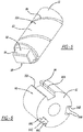
- the cross-pin 30A includes a cylindrical pin body 80 that extends between a first end 82 and a second end 84.
- the cylindrical pin body 80 has a spiral groove 88 formed thereon for oil retention and to maintain an oil film between the pinion gear 40A and the cross-pin 30A.
- the oil film will minimize friction during relative motion between the pinion gear 40A and the cross-pin 30A.
- the second end 84 can have a generally rectangular geometry including first parallel sides 88.
- the first parallel sides 88 can be suitable for mating in a non-rotatable keyed relationship with a center block 90.
- the center block 90 generally includes a cylindrical block body 92 having a series of locating features 94A, 94B and 94C formed thereon.
- the locating features 94A, 94B and 94C are in the form of slots that extend a length of the cylindrical block body 92.
- the locating features 94A, 94B and 94C can each be defined in part by opposing side walls 96A, 96B and 96C.
- the locating features 94A, 94B and 94C are configured to slidingly receive and oppose the second end 84 of the respective cross-pins 30A, 30B and 30C (see also FIG. 2 ) in a nested position.
- the second ends 84 are slidingly received by the locating features 94A, 94B and 94C.
- the center block 90 can be sandwiched between the side gears 20 and 22 and generally retained therebetween. Assembly can be accomplished by slidably passing the center block 90 into location against the side gear 22 while locating the respective second ends 84 along the locating features 94A, 94B and 94C of the center block 90.
- the locating features 94A, 94B and 94C prevent rotation of the cross-pins 30A, 30B and 30C as the second ends 84 (see FIG. 5 ) are keyed into the respective locating features 94A, 94B and 94C.
- the respective ends 84 keep the center block 90 from rotating.
- deflection of the cross-pins 30A, 30B and 30C is limited to a desired value. This will inhibit the cross-shaft contact at the transition between the holes 70A, 70b and 70C and counterbores 72A, 72B and 72C under load such that the respective cross-pins 30A, 30B and 30C are constrained from rotating.
- the cross-pins 30A, 30B and 30C are supported at both ends.
- the differential gear assembly 12 could not be assembled.
- the case 16 would need to be split such as at the cross-shaft centerline.
- extra fasteners would also be required to hold the two separate halves of the case together.
- the differential gear assembly 12 can be assembled from the open end on the flange side (see for example the view seen from FIG. 2 ).
- Three pinions for higher torque capacity can be incorporated with the instant design as compared to a two pinion design having one larger cross-pin.
Landscapes
- Engineering & Computer Science (AREA)
- General Engineering & Computer Science (AREA)
- Mechanical Engineering (AREA)
- Retarders (AREA)
Claims (14)
- Differentialgetriebemechanismus (12), umfassend:ein Differentialgehäuse (16), das eine erste, zweite und dritte Senkbohrung (72A, 72B, 72C) definiert, die um dieses herum ausgebildet sind, wobei sich das Differentialgehäuse um eine Rotationsachse (19) dreht;ein erstes und ein zweites Kegelrad (20, 22), die drehbar innerhalb des Differentialgehäuses (16) montiert sind, wobei das erste und das zweite Kegelrad koaxial entlang der Rotationsachse (19) ausgerichtet sind;ein erstes, zweites und drittes Ritzel (40A, 40B, 40C), die zwischen dem ersten und zweiten Kegelrad (20, 22) montiert sind, wobei jedes vom ersten, zweiten und dritten Ritzel drehbar auf einem jeweiligen Querbolzen (30A, 30B, 30C) montiert ist, wobei jeder Querbolzen einen zylindrischen Bolzenkörper (80) aufweist, der sich zwischen einem ersten und zweiten Ende (82, 84) erstreckt, wobei das erste, zweite und dritte Ritzel mit dem ersten und dem zweiten Kegelrad ineinander greifen, um eine Drehmomentübertragungsanordnung zu bilden, die zum Übertragen von Drehmoment zwischen den Ritzeln und dem ersten und zweiten Kegelrad konfiguriert ist, um das erste und zweite Kegelrad um die Rotationsachse zu drehen;dadurch gekennzeichnet, dass derDifferentialgetriebemechanismus (12) ferner umfasst:einen Mittelblock (90) mit einem zylindrischen Blockkörper (92), der ein erstes, zweites und drittes Positionierungsmerkmal (94A, 94B, 94C) darauf definiert, wobei der Mittelblock zwischen dem ersten und zweiten Kegelrad (20, 22) angeordnet ist; undwobei jedes erste Ende eines jeweiligen Querbolzens (30A, 30B, 30C) von einer entsprechenden Senkbohrung (72A, 72B, 72C) des Differentialgehäuses (16) aufgenommen wird und jedes zweite Ende (84) von einem entsprechenden Positionierungsmerkmal (94A, 94B, 94C) des Mittelblocks (90) aufgenommen wird, wobei die Positionierungsmerkmale (94A, 94B, 94C) in dem Mittelblock (90) jeweils teilweise durch gegenüberliegende Seitenwände (96A, 96B, 96C) definiert sind, die den jeweiligen zweiten Enden (84) der Querbolzen (30A, 30B, 30C) in einer formschlüssigen Beziehung gegenüberliegen.
- Differentialgetriebemechanismus nach Anspruch 1, wobei das erste, zweite und dritte Positionierungsmerkmal (94A, 94B, 94C) einen ersten, zweiten und dritten Schlitz umfasst, die in dem zylindrischen Blockkörper (92) ausgebildet sind.
- Differentialgetriebemechanismus nach Anspruch 1, wobei das Differentialgehäuse (16) ferner ein erstes, zweites und drittes Loch (70A, 70B, 70C) definiert, die koaxial relativ zu der jeweiligen ersten, zweiten und dritten Senkbohrung (72A, 72B, 72C) angeordnet sind.
- Differentialgetriebemechanismus nach Anspruch 1, wobei die Drehmomentübertragungsanordnung dazu konfiguriert ist zu ermöglichen, dass sich das erste und das zweite Kegelrad (20, 22) mit unterschiedlichen Drehzahlen in Bezug zueinander um die Rotationsachse (19) drehen.
- Differentialgetriebemechanismus nach Anspruch 4, wobei:das Differentialgehäuse (16) ein erstes, zweites und drittes Loch (70A, 70B, 70C) und eine entsprechende erste, zweite und dritte Senkbohrung, die um diese herum ausgebildet sind, definiert; undwobei der Mittelblock einen zylindrischen Blockkörper aufweist, der einen ersten, zweiten und dritten Schlitz darauf definiert.
- Differentialgetriebemechanismus nach Anspruch 1 oder 5, wobei jeder zylindrische Bolzenkörper (80) eine daran ausgebildete Spiralnut (88) aufweist.
- Differentialgetriebemechanismus nach Anspruch 3 oder 5, wobei das Differentialgehäuse (16) ferner ein erstes, ein zweites und ein drittes Fenster (76A, 76B, 76C) definiert, die an einer diametral gegenüberliegenden Stelle von einem entsprechenden ersten, zweiten und dritten Loch (70A, 70B, 70C) in dem Differentialgehäuse positioniert sind.
- Differentialgetriebemechanismus nach Anspruch 7, wenn abhängig von Anspruch 5, wobei das erste, zweite und dritte Fenster (76A, 76B, 76C) dazu konfiguriert sind, Werkzeugzugriff auf das Differentialgehäuse (16) während der Bildung der jeweiligen ersten, zweiten und dritten Senkbohrung (72A, 72B, 72C) zu ermöglichen.
- Differentialgetriebemechanismus nach Anspruch 6, wobei die Schlitze in dem Mittelblock (90) jeweils teilweise durch gegenüberliegende Seitenwände (96A, 96B, 96C) definiert sind, die den jeweiligen zweiten Enden (84) der Querbolzen (30A, 30B, 30C) gegenüberliegen.
- Differentialgetriebemechanismus nach Anspruch 5, wobei die Querbolzen mit dem Mittelblock (90) an den jeweiligen Schlitzen formschlüssig verbunden sind.
- Differentialgetriebemechanismus nach Anspruch 1 oder 5, wobei der Mittelblock (90) zwischen den Kegelrädern (20, 22) gehalten wird.
- Differentialgetriebemechanismus nach Anspruch 2 oder 5, wobei sich die jeweiligen Schlitze jeweils über eine Länge des zylindrischen Blockkörpers (92) erstrecken.
- Differentialgetriebemechanismus nach Anspruch 3 oder 5, wobei sich jedes der ersten, zweiten und dritten Löcher (70A, 70B, 70C) durch eine Außenfläche des Differentialgehäuses (16) erstreckt.
- Differentialgetriebemechanismus nach Anspruch 5, wobei jedes jeweilige zweite Ende (84) eine im Allgemeinen rechteckige Geometrie aufweist.
Applications Claiming Priority (2)
| Application Number | Priority Date | Filing Date | Title |
|---|---|---|---|
| IN955DE2015 | 2015-04-03 | ||
| PCT/US2016/024433 WO2016160657A1 (en) | 2015-04-03 | 2016-03-28 | Cross-shaft for three pinion differential |
Publications (3)
| Publication Number | Publication Date |
|---|---|
| EP3277982A1 EP3277982A1 (de) | 2018-02-07 |
| EP3277982A4 EP3277982A4 (de) | 2018-12-05 |
| EP3277982B1 true EP3277982B1 (de) | 2020-12-30 |
Family
ID=57007150
Family Applications (1)
| Application Number | Title | Priority Date | Filing Date |
|---|---|---|---|
| EP16773899.6A Active EP3277982B1 (de) | 2015-04-03 | 2016-03-28 | Querwelle für differential mit drei ritzeln |
Country Status (4)
| Country | Link |
|---|---|
| US (1) | US10539215B2 (de) |
| EP (1) | EP3277982B1 (de) |
| CN (1) | CN107667235B (de) |
| WO (1) | WO2016160657A1 (de) |
Families Citing this family (4)
| Publication number | Priority date | Publication date | Assignee | Title |
|---|---|---|---|---|
| US10113627B2 (en) * | 2017-02-02 | 2018-10-30 | American Axle & Manufacturing, Inc. | Differential assembly with multi-piece cross-pin |
| EP4015872B1 (de) * | 2020-12-18 | 2025-12-24 | Ningbo Geely Automobile Research & Development Co. Ltd. | Differentialgetriebeanordnung, fahrzeug mit einer differentialgetriebeanordnung und verfahren zum zusammenbau von teilen einer differentialgetriebeanordnung |
| CN115823207A (zh) | 2022-11-10 | 2023-03-21 | 华为数字能源技术有限公司 | 差速器、动力总成及车辆 |
| CN118046749A (zh) * | 2024-01-02 | 2024-05-17 | 浙江极氪智能科技有限公司 | 车轮驱动机构和具有其的车辆 |
Family Cites Families (23)
| Publication number | Priority date | Publication date | Assignee | Title |
|---|---|---|---|---|
| US2200153A (en) * | 1938-08-02 | 1940-05-07 | Bush Earl | Differential |
| US3052137A (en) * | 1959-02-27 | 1962-09-04 | Eaton Mfg Co | Differential mechanism |
| US3109323A (en) * | 1960-09-08 | 1963-11-05 | Thornton Products Company | Hydraulic locking differential |
| US3049942A (en) * | 1961-01-03 | 1962-08-21 | Kohler Conrad Dings | Differential with automatic slip control |
| US3232139A (en) * | 1962-02-02 | 1966-02-01 | Claude H Nickell | Hydraulically operated partial lock differential |
| US3893351A (en) * | 1973-06-19 | 1975-07-08 | Eaton Corp | Limited slip differential drive mechanism |
| US4183263A (en) * | 1976-07-01 | 1980-01-15 | Dana Corporation | Differential mechanism |
| FR2456887A1 (fr) * | 1979-05-18 | 1980-12-12 | Renault | Differentiel de transmission |
| US4860614A (en) * | 1988-07-26 | 1989-08-29 | Deere & Company | Transmission differential |
| GB9017927D0 (en) * | 1990-08-15 | 1990-09-26 | Rolls Royce Motor Cars | A differential assembly |
| CA2102612C (en) * | 1991-05-08 | 1996-09-17 | Dana Corporation | Limited slip differential incorporating bevel pinions |
| JPWO2004013519A1 (ja) * | 2002-08-02 | 2006-06-22 | 株式会社音戸工作所 | 車両用差動装置 |
| JPWO2004036088A1 (ja) * | 2002-10-21 | 2006-02-16 | 株式会社音戸工作所 | 車両用差動装置 |
| US7025702B2 (en) * | 2002-12-24 | 2006-04-11 | Yanagawa Seiki Co., Ltd. | Differential |
| DE102004008224B4 (de) * | 2003-02-21 | 2007-05-31 | Tochigi Fuji Sangyo K.K. | Differentialvorrichtung |
| WO2004076891A1 (ja) * | 2003-02-27 | 2004-09-10 | Ondo Corporation | 車両用差動装置 |
| US20070191171A1 (en) * | 2003-09-15 | 2007-08-16 | Pascoe David M | Differential with die formed housing |
| JP4815889B2 (ja) * | 2005-06-17 | 2011-11-16 | 株式会社ジェイテクト | 車両用差動歯車装置 |
| WO2009014673A2 (en) * | 2007-07-19 | 2009-01-29 | Metaldyne Company Llc | Support structure for differential |
| JP2012145206A (ja) * | 2011-01-14 | 2012-08-02 | Nippon Soken Inc | 差動装置 |
| KR101403824B1 (ko) * | 2011-08-04 | 2014-06-03 | 도요타지도샤가부시키가이샤 | 용접 구조 및 용접 구조의 제조 방법 |
| US8951159B2 (en) * | 2012-10-10 | 2015-02-10 | Eaton Corporation | Differential case having lock pins in-line with clutch ear guides |
| CN202926990U (zh) * | 2012-11-15 | 2013-05-08 | 中国重汽集团济南动力有限公司 | 一种轴间差速器 |
-
2016
- 2016-03-28 EP EP16773899.6A patent/EP3277982B1/de active Active
- 2016-03-28 CN CN201680031318.3A patent/CN107667235B/zh active Active
- 2016-03-28 WO PCT/US2016/024433 patent/WO2016160657A1/en not_active Ceased
-
2017
- 2017-10-03 US US15/723,678 patent/US10539215B2/en active Active
Non-Patent Citations (1)
| Title |
|---|
| None * |
Also Published As
| Publication number | Publication date |
|---|---|
| US10539215B2 (en) | 2020-01-21 |
| CN107667235A (zh) | 2018-02-06 |
| US20180023677A1 (en) | 2018-01-25 |
| WO2016160657A1 (en) | 2016-10-06 |
| EP3277982A4 (de) | 2018-12-05 |
| EP3277982A1 (de) | 2018-02-07 |
| CN107667235B (zh) | 2020-10-09 |
Similar Documents
| Publication | Publication Date | Title |
|---|---|---|
| EP3030806B1 (de) | Schlupfbegrenztes differential mit trennung von kupplung und aktuator | |
| US8827859B2 (en) | Differential having two-piece case split through planetary carrier wall | |
| US9791031B2 (en) | Differential having compact bevel cross shaft retention using case bolts and adjacent shafts | |
| US9709150B2 (en) | Differential having piston housing integrated with differential case | |
| AU2006205639B2 (en) | Electronically actuated locking differential | |
| US10539215B2 (en) | Cross-shaft for three pinion differential | |
| US5531653A (en) | Selectively lockable differential assembly | |
| US11940038B2 (en) | Clutch pack with lock plates | |
| KR102537272B1 (ko) | 차동 제한 장치를 위한 비동기식 기어 맞물림 이벤트 | |
| US4569250A (en) | Positive drive with torque responsive dampener | |
| EP3353447B1 (de) | Elektrohydraulisches sperrdifferenzialsystem | |
| US5924948A (en) | Differential drive | |
| EP1340006B1 (de) | Komponentensystem zum beeinflüssen eines standarddifferentials |
Legal Events
| Date | Code | Title | Description |
|---|---|---|---|
| STAA | Information on the status of an ep patent application or granted ep patent |
Free format text: STATUS: THE INTERNATIONAL PUBLICATION HAS BEEN MADE |
|
| PUAI | Public reference made under article 153(3) epc to a published international application that has entered the european phase |
Free format text: ORIGINAL CODE: 0009012 |
|
| STAA | Information on the status of an ep patent application or granted ep patent |
Free format text: STATUS: REQUEST FOR EXAMINATION WAS MADE |
|
| 17P | Request for examination filed |
Effective date: 20171013 |
|
| AK | Designated contracting states |
Kind code of ref document: A1 Designated state(s): AL AT BE BG CH CY CZ DE DK EE ES FI FR GB GR HR HU IE IS IT LI LT LU LV MC MK MT NL NO PL PT RO RS SE SI SK SM TR |
|
| AX | Request for extension of the european patent |
Extension state: BA ME |
|
| RIN1 | Information on inventor provided before grant (corrected) |
Inventor name: WADHVA, ASHISH |
|
| DAV | Request for validation of the european patent (deleted) | ||
| DAX | Request for extension of the european patent (deleted) | ||
| A4 | Supplementary search report drawn up and despatched |
Effective date: 20181025 |
|
| RIC1 | Information provided on ipc code assigned before grant |
Ipc: F16H 48/08 20060101ALI20181020BHEP Ipc: F16H 48/12 20120101ALI20181020BHEP Ipc: F16H 48/40 20120101AFI20181020BHEP |
|
| REG | Reference to a national code |
Ref country code: DE Ref legal event code: R079 Ref document number: 602016050645 Country of ref document: DE Free format text: PREVIOUS MAIN CLASS: F16H0048380000 Ipc: F16H0048400000 |
|
| RIC1 | Information provided on ipc code assigned before grant |
Ipc: F16H 48/08 20060101ALI20200203BHEP Ipc: F16H 48/40 20120101AFI20200203BHEP Ipc: F16H 48/12 20120101ALI20200203BHEP |
|
| GRAP | Despatch of communication of intention to grant a patent |
Free format text: ORIGINAL CODE: EPIDOSNIGR1 |
|
| STAA | Information on the status of an ep patent application or granted ep patent |
Free format text: STATUS: GRANT OF PATENT IS INTENDED |
|
| GRAJ | Information related to disapproval of communication of intention to grant by the applicant or resumption of examination proceedings by the epo deleted |
Free format text: ORIGINAL CODE: EPIDOSDIGR1 |
|
| STAA | Information on the status of an ep patent application or granted ep patent |
Free format text: STATUS: REQUEST FOR EXAMINATION WAS MADE |
|
| INTG | Intention to grant announced |
Effective date: 20200514 |
|
| INTC | Intention to grant announced (deleted) | ||
| GRAP | Despatch of communication of intention to grant a patent |
Free format text: ORIGINAL CODE: EPIDOSNIGR1 |
|
| STAA | Information on the status of an ep patent application or granted ep patent |
Free format text: STATUS: GRANT OF PATENT IS INTENDED |
|
| INTG | Intention to grant announced |
Effective date: 20200805 |
|
| RAP1 | Party data changed (applicant data changed or rights of an application transferred) |
Owner name: EATON INTELLIGENT POWER LIMITED |
|
| GRAS | Grant fee paid |
Free format text: ORIGINAL CODE: EPIDOSNIGR3 |
|
| GRAA | (expected) grant |
Free format text: ORIGINAL CODE: 0009210 |
|
| STAA | Information on the status of an ep patent application or granted ep patent |
Free format text: STATUS: THE PATENT HAS BEEN GRANTED |
|
| AK | Designated contracting states |
Kind code of ref document: B1 Designated state(s): AL AT BE BG CH CY CZ DE DK EE ES FI FR GB GR HR HU IE IS IT LI LT LU LV MC MK MT NL NO PL PT RO RS SE SI SK SM TR |
|
| REG | Reference to a national code |
Ref country code: GB Ref legal event code: FG4D |
|
| REG | Reference to a national code |
Ref country code: AT Ref legal event code: REF Ref document number: 1350254 Country of ref document: AT Kind code of ref document: T Effective date: 20210115 |
|
| REG | Reference to a national code |
Ref country code: DE Ref legal event code: R096 Ref document number: 602016050645 Country of ref document: DE |
|
| REG | Reference to a national code |
Ref country code: IE Ref legal event code: FG4D |
|
| PG25 | Lapsed in a contracting state [announced via postgrant information from national office to epo] |
Ref country code: RS Free format text: LAPSE BECAUSE OF FAILURE TO SUBMIT A TRANSLATION OF THE DESCRIPTION OR TO PAY THE FEE WITHIN THE PRESCRIBED TIME-LIMIT Effective date: 20201230 Ref country code: NO Free format text: LAPSE BECAUSE OF FAILURE TO SUBMIT A TRANSLATION OF THE DESCRIPTION OR TO PAY THE FEE WITHIN THE PRESCRIBED TIME-LIMIT Effective date: 20210330 Ref country code: GR Free format text: LAPSE BECAUSE OF FAILURE TO SUBMIT A TRANSLATION OF THE DESCRIPTION OR TO PAY THE FEE WITHIN THE PRESCRIBED TIME-LIMIT Effective date: 20210331 Ref country code: FI Free format text: LAPSE BECAUSE OF FAILURE TO SUBMIT A TRANSLATION OF THE DESCRIPTION OR TO PAY THE FEE WITHIN THE PRESCRIBED TIME-LIMIT Effective date: 20201230 |
|
| REG | Reference to a national code |
Ref country code: AT Ref legal event code: MK05 Ref document number: 1350254 Country of ref document: AT Kind code of ref document: T Effective date: 20201230 |
|
| PG25 | Lapsed in a contracting state [announced via postgrant information from national office to epo] |
Ref country code: BG Free format text: LAPSE BECAUSE OF FAILURE TO SUBMIT A TRANSLATION OF THE DESCRIPTION OR TO PAY THE FEE WITHIN THE PRESCRIBED TIME-LIMIT Effective date: 20210330 Ref country code: LV Free format text: LAPSE BECAUSE OF FAILURE TO SUBMIT A TRANSLATION OF THE DESCRIPTION OR TO PAY THE FEE WITHIN THE PRESCRIBED TIME-LIMIT Effective date: 20201230 Ref country code: SE Free format text: LAPSE BECAUSE OF FAILURE TO SUBMIT A TRANSLATION OF THE DESCRIPTION OR TO PAY THE FEE WITHIN THE PRESCRIBED TIME-LIMIT Effective date: 20201230 |
|
| REG | Reference to a national code |
Ref country code: NL Ref legal event code: MP Effective date: 20201230 |
|
| PG25 | Lapsed in a contracting state [announced via postgrant information from national office to epo] |
Ref country code: HR Free format text: LAPSE BECAUSE OF FAILURE TO SUBMIT A TRANSLATION OF THE DESCRIPTION OR TO PAY THE FEE WITHIN THE PRESCRIBED TIME-LIMIT Effective date: 20201230 |
|
| REG | Reference to a national code |
Ref country code: LT Ref legal event code: MG9D |
|
| PG25 | Lapsed in a contracting state [announced via postgrant information from national office to epo] |
Ref country code: LT Free format text: LAPSE BECAUSE OF FAILURE TO SUBMIT A TRANSLATION OF THE DESCRIPTION OR TO PAY THE FEE WITHIN THE PRESCRIBED TIME-LIMIT Effective date: 20201230 Ref country code: EE Free format text: LAPSE BECAUSE OF FAILURE TO SUBMIT A TRANSLATION OF THE DESCRIPTION OR TO PAY THE FEE WITHIN THE PRESCRIBED TIME-LIMIT Effective date: 20201230 Ref country code: CZ Free format text: LAPSE BECAUSE OF FAILURE TO SUBMIT A TRANSLATION OF THE DESCRIPTION OR TO PAY THE FEE WITHIN THE PRESCRIBED TIME-LIMIT Effective date: 20201230 Ref country code: PT Free format text: LAPSE BECAUSE OF FAILURE TO SUBMIT A TRANSLATION OF THE DESCRIPTION OR TO PAY THE FEE WITHIN THE PRESCRIBED TIME-LIMIT Effective date: 20210430 Ref country code: RO Free format text: LAPSE BECAUSE OF FAILURE TO SUBMIT A TRANSLATION OF THE DESCRIPTION OR TO PAY THE FEE WITHIN THE PRESCRIBED TIME-LIMIT Effective date: 20201230 Ref country code: SK Free format text: LAPSE BECAUSE OF FAILURE TO SUBMIT A TRANSLATION OF THE DESCRIPTION OR TO PAY THE FEE WITHIN THE PRESCRIBED TIME-LIMIT Effective date: 20201230 |
|
| PG25 | Lapsed in a contracting state [announced via postgrant information from national office to epo] |
Ref country code: PL Free format text: LAPSE BECAUSE OF FAILURE TO SUBMIT A TRANSLATION OF THE DESCRIPTION OR TO PAY THE FEE WITHIN THE PRESCRIBED TIME-LIMIT Effective date: 20201230 Ref country code: AT Free format text: LAPSE BECAUSE OF FAILURE TO SUBMIT A TRANSLATION OF THE DESCRIPTION OR TO PAY THE FEE WITHIN THE PRESCRIBED TIME-LIMIT Effective date: 20201230 |
|
| PG25 | Lapsed in a contracting state [announced via postgrant information from national office to epo] |
Ref country code: IS Free format text: LAPSE BECAUSE OF FAILURE TO SUBMIT A TRANSLATION OF THE DESCRIPTION OR TO PAY THE FEE WITHIN THE PRESCRIBED TIME-LIMIT Effective date: 20210430 |
|
| REG | Reference to a national code |
Ref country code: DE Ref legal event code: R097 Ref document number: 602016050645 Country of ref document: DE |
|
| PG25 | Lapsed in a contracting state [announced via postgrant information from national office to epo] |
Ref country code: AL Free format text: LAPSE BECAUSE OF FAILURE TO SUBMIT A TRANSLATION OF THE DESCRIPTION OR TO PAY THE FEE WITHIN THE PRESCRIBED TIME-LIMIT Effective date: 20201230 Ref country code: IT Free format text: LAPSE BECAUSE OF FAILURE TO SUBMIT A TRANSLATION OF THE DESCRIPTION OR TO PAY THE FEE WITHIN THE PRESCRIBED TIME-LIMIT Effective date: 20201230 Ref country code: MC Free format text: LAPSE BECAUSE OF FAILURE TO SUBMIT A TRANSLATION OF THE DESCRIPTION OR TO PAY THE FEE WITHIN THE PRESCRIBED TIME-LIMIT Effective date: 20201230 |
|
| REG | Reference to a national code |
Ref country code: CH Ref legal event code: PL |
|
| PLBE | No opposition filed within time limit |
Free format text: ORIGINAL CODE: 0009261 |
|
| STAA | Information on the status of an ep patent application or granted ep patent |
Free format text: STATUS: NO OPPOSITION FILED WITHIN TIME LIMIT |
|
| GBPC | Gb: european patent ceased through non-payment of renewal fee |
Effective date: 20210330 |
|
| PG25 | Lapsed in a contracting state [announced via postgrant information from national office to epo] |
Ref country code: DK Free format text: LAPSE BECAUSE OF FAILURE TO SUBMIT A TRANSLATION OF THE DESCRIPTION OR TO PAY THE FEE WITHIN THE PRESCRIBED TIME-LIMIT Effective date: 20201230 |
|
| 26N | No opposition filed |
Effective date: 20211001 |
|
| REG | Reference to a national code |
Ref country code: BE Ref legal event code: MM Effective date: 20210331 |
|
| PG25 | Lapsed in a contracting state [announced via postgrant information from national office to epo] |
Ref country code: LU Free format text: LAPSE BECAUSE OF NON-PAYMENT OF DUE FEES Effective date: 20210328 Ref country code: LI Free format text: LAPSE BECAUSE OF NON-PAYMENT OF DUE FEES Effective date: 20210331 Ref country code: CH Free format text: LAPSE BECAUSE OF NON-PAYMENT OF DUE FEES Effective date: 20210331 Ref country code: ES Free format text: LAPSE BECAUSE OF FAILURE TO SUBMIT A TRANSLATION OF THE DESCRIPTION OR TO PAY THE FEE WITHIN THE PRESCRIBED TIME-LIMIT Effective date: 20201230 Ref country code: FR Free format text: LAPSE BECAUSE OF NON-PAYMENT OF DUE FEES Effective date: 20210331 Ref country code: GB Free format text: LAPSE BECAUSE OF NON-PAYMENT OF DUE FEES Effective date: 20210330 Ref country code: IE Free format text: LAPSE BECAUSE OF NON-PAYMENT OF DUE FEES Effective date: 20210328 |
|
| PG25 | Lapsed in a contracting state [announced via postgrant information from national office to epo] |
Ref country code: SI Free format text: LAPSE BECAUSE OF FAILURE TO SUBMIT A TRANSLATION OF THE DESCRIPTION OR TO PAY THE FEE WITHIN THE PRESCRIBED TIME-LIMIT Effective date: 20201230 |
|
| PG25 | Lapsed in a contracting state [announced via postgrant information from national office to epo] |
Ref country code: IS Free format text: LAPSE BECAUSE OF FAILURE TO SUBMIT A TRANSLATION OF THE DESCRIPTION OR TO PAY THE FEE WITHIN THE PRESCRIBED TIME-LIMIT Effective date: 20210430 |
|
| PG25 | Lapsed in a contracting state [announced via postgrant information from national office to epo] |
Ref country code: BE Free format text: LAPSE BECAUSE OF NON-PAYMENT OF DUE FEES Effective date: 20210331 |
|
| P01 | Opt-out of the competence of the unified patent court (upc) registered |
Effective date: 20230521 |
|
| PG25 | Lapsed in a contracting state [announced via postgrant information from national office to epo] |
Ref country code: NL Free format text: LAPSE BECAUSE OF NON-PAYMENT OF DUE FEES Effective date: 20201230 Ref country code: CY Free format text: LAPSE BECAUSE OF FAILURE TO SUBMIT A TRANSLATION OF THE DESCRIPTION OR TO PAY THE FEE WITHIN THE PRESCRIBED TIME-LIMIT Effective date: 20201230 |
|
| PG25 | Lapsed in a contracting state [announced via postgrant information from national office to epo] |
Ref country code: SM Free format text: LAPSE BECAUSE OF FAILURE TO SUBMIT A TRANSLATION OF THE DESCRIPTION OR TO PAY THE FEE WITHIN THE PRESCRIBED TIME-LIMIT Effective date: 20201230 Ref country code: HU Free format text: LAPSE BECAUSE OF FAILURE TO SUBMIT A TRANSLATION OF THE DESCRIPTION OR TO PAY THE FEE WITHIN THE PRESCRIBED TIME-LIMIT; INVALID AB INITIO Effective date: 20160328 |
|
| PG25 | Lapsed in a contracting state [announced via postgrant information from national office to epo] |
Ref country code: MK Free format text: LAPSE BECAUSE OF FAILURE TO SUBMIT A TRANSLATION OF THE DESCRIPTION OR TO PAY THE FEE WITHIN THE PRESCRIBED TIME-LIMIT Effective date: 20201230 |
|
| PG25 | Lapsed in a contracting state [announced via postgrant information from national office to epo] |
Ref country code: MT Free format text: LAPSE BECAUSE OF FAILURE TO SUBMIT A TRANSLATION OF THE DESCRIPTION OR TO PAY THE FEE WITHIN THE PRESCRIBED TIME-LIMIT Effective date: 20201230 |
|
| PG25 | Lapsed in a contracting state [announced via postgrant information from national office to epo] |
Ref country code: TR Free format text: LAPSE BECAUSE OF FAILURE TO SUBMIT A TRANSLATION OF THE DESCRIPTION OR TO PAY THE FEE WITHIN THE PRESCRIBED TIME-LIMIT Effective date: 20201230 |
|
| PGFP | Annual fee paid to national office [announced via postgrant information from national office to epo] |
Ref country code: DE Payment date: 20260219 Year of fee payment: 11 |