EP3279129A1 - Cabine d'ascenseur - Google Patents
Cabine d'ascenseur Download PDFInfo
- Publication number
- EP3279129A1 EP3279129A1 EP17191675.2A EP17191675A EP3279129A1 EP 3279129 A1 EP3279129 A1 EP 3279129A1 EP 17191675 A EP17191675 A EP 17191675A EP 3279129 A1 EP3279129 A1 EP 3279129A1
- Authority
- EP
- European Patent Office
- Prior art keywords
- car
- cage
- disposed
- mounting bracket
- ceiling
- Prior art date
- Legal status (The legal status is an assumption and is not a legal conclusion. Google has not performed a legal analysis and makes no representation as to the accuracy of the status listed.)
- Granted
Links
Images







Classifications
-
- B—PERFORMING OPERATIONS; TRANSPORTING
- B66—HOISTING; LIFTING; HAULING
- B66B—ELEVATORS; ESCALATORS OR MOVING WALKWAYS
- B66B11/00—Main component parts of lifts in, or associated with, buildings or other structures
- B66B11/02—Cages, i.e. cars
- B66B11/0226—Constructional features, e.g. walls assembly, decorative panels, comfort equipment, thermal or sound insulation
-
- B—PERFORMING OPERATIONS; TRANSPORTING
- B66—HOISTING; LIFTING; HAULING
- B66B—ELEVATORS; ESCALATORS OR MOVING WALKWAYS
- B66B13/00—Doors, gates, or other apparatus controlling access to, or exit from, cages or lift well landings
- B66B13/30—Constructional features of doors or gates
Definitions
- the present invention relates to an elevator car and particularly relates to a mounting construction for a beam on which a hanger rail that guides opening and closing of a car door is disposed.
- a beam is mounted onto a car frame that supports a cage by means of a mounting arm.
- a hanger rail that guides opening and closing of a car door is disposed on the beam.
- a reinforcing rod is linked obliquely between the mounting arm and the car frame (see Patent Literature 1, for example).
- reinforcing materials are disposed on an outer surface of a cage without using a car frame.
- a pair of side wall reinforcing materials are disposed on outer surfaces of a pair of side walls of the cage, and a ceiling reinforcing material is disposed on an outer surface of a ceiling of the cage.
- a pair of brackets are fastened between the side wall reinforcing materials and the ceiling reinforcing materials.
- a beam of a car door apparatus is fastened to the brackets, a doorway frame, and the ceiling (see Patent Literature 2, for example).
- Patent Literature 1 Because members such as rods, a mounting arm, etc., are required in order to mount the beam onto the car frame, the number of parts is increased. Because the beam is mounted onto the car frame, installation and adjustment such as centering to align the center of the car doorway that is disposed on the cage and the center of the beam are time-consuming.
- Patent Literature 2 Because the conventional car construction that is disclosed in Patent Literature 2 has a simple construction that does not use a car frame, on the other hand, it can be applied only to small elevators. Because the construction does not support the cage on a car frame by means of rubber vibration isolators, riding comfort is impaired. In addition, using this construction, installation and adjustment such as centering to align the center of the car doorway and the center of the beam is also time-consuming.
- the present invention aims to solve the above problems and an object of the present invention is to provide an elevator car that can facilitate installation and adjustment of a beam by a simple configuration while avoiding deterioration in riding comfort.
- an elevator car including: a car frame; a cage that is supported by the car frame, and on which a car doorway is disposed; a beam that is disposed above the car doorway, and on which a hanger rail is disposed; and a car door that is moved along the hanger rail to open and close the car doorway
- the cage has: a pair of wing walls that are disposed on two sides of the car doorway; and a doorway top plate that is disposed on an upper portion of the car doorway, and two end portions of which are fastened to the wing wall; a beam mounting bracket is mounted onto fastening portions between the wing wall and the doorway top plate; and the beam is mounted onto the cage by means of the beam mounting bracket.
- an elevator car including: a car frame; a cage that is supported by the car frame, and on which a car doorway is disposed; a beam that is disposed above the car doorway, and on which a hanger rail is disposed; and a car door that is moved along the hanger rail to open and close the car doorway, wherein: a beam mounting bracket is mounted above a ceiling of the cage; the beam is mounted onto the cage by means of the beam mounting bracket; and the beam mounting bracket is disposed along a front edge portion of the ceiling over an entire width direction of the cage.
- an elevator car that can facilitate installation and adjustment of a beam by a simple configuration while avoiding deterioration in riding comfort.
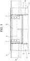
- FIG 1 is a front elevation that shows an elevator cage front surface upper portion according to Embodiment 1 of the present invention
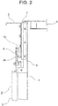
- Figure 2 is a side elevation that shows the cage front surface upper portion in Figure 1
- Figure 3 is a plan that shows the cage front surface upper portion in Figure 1 .
- An elevator car has: a car frame (not shown); a cage 1 that is supported by the car frame, and on which a car doorway 1 a is disposed; a beam 2 that is disposed above the car doorway 1 a of the cage 1, and on which a hanger rail 2a is disposed; and a pair of car doors 3 that are moved along the hanger rail 2a to open and close the car doorway 1 a.
- a cage 1 has: a pair of wing walls 4 that are disposed on two sides of the car doorway 1a; a doorway top plate 5 that is disposed on an upper portion of the car doorway 1 a, and two end portions of which are fastened to the wing walls; a rear wall (not shown) that faces the car doorway 1 a; a pair of left and right side walls (not shown); and a ceiling (a canopy) 6.
- a pair of beam mounting brackets 7 are mounted onto fastening portions between the wing walls 4 and the doorway top plate 5.
- the beam mounting brackets 7 are fastened together with the fastening portions between the wing walls 4 and the doorway top plate 5 by a plurality of fasteners (nuts and bolts).
- the beam 2 is mounted onto the beam mounting brackets 7. In other words, the beam 2 is mounted onto the cage 1 by means of the beam mounting brackets 7.
- Each of the car doors 3 has: a car door panel 8 that opens and closes the car doorway 1 a; and a door hanger 9 that is fixed to an upper portion of the car door panel 8.
- a plurality of hanger rollers 10 that roll on the hanger rail 2a are disposed on the door hanger 9.
- the car door panels 8 are suspended from the hanger rail 2a by means of the door hangers 9.
- the beam 2 is mounted onto beam mounting brackets 7 that are mounted onto the cage 1 using the fastening portions between the wing walls 4 and the doorway top plate 5, the beam 2 can be mounted onto the cage 1 by a simple configuration using a small number of parts, enabling reductions in weight and reductions in cost to be achieved.
- the beam 2 can also be mounted onto the cage 1 using the side surfaces of the wing walls 4 as references, enabling installation and adjustment such as centering to align the center of the car doorway 1a and the center of the beam 2 to be facilitated, thereby enabling labor saving to be achieved in installation work. Gap adjustment between the car doors 3 and the cage 1 can also be simplified, and time spent on clearance control of engaging apparatus (not shown) during running can be saved.
- the beam 2 is disposed in front of the cage 1, it is possible to suppress the height of the car doors 3 even if ceiling height is increased, enabling reductions in grade and reductions in materials to be achieved.
- a vibration absorbing material such as vibration absorbing rubber, etc., can be interposed between the car frame and the cage 1, enabling deterioration in riding comfort to be prevented.
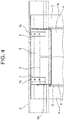
- Figure 4 is a front elevation that shows an elevator cage front surface upper portion according to Embodiment 2 of the present invention
- Figure 5 is a side elevation that shows the cage front surface upper portion in Figure 4
- Figure 6 is a plan that shows the cage front surface upper portion in Figure 4 .
- ceiling fastening portions 7a that are fastened to a ceiling 6 are disposed on upper end portions of beam mounting brackets 7.
- the beam mounting brackets 7 according to Embodiment 2 are also fastened to the ceiling 6 in addition to fastening portions between the wing walls 4 and the doorway top plate 5.
- the ceiling fastening portions 7a are fastened together with fastening portions between the ceiling 6 and the doorway top plate 5.
- the rest of the configuration is similar or identical to that of Embodiment 1.
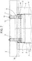
- Figure 7 is a front elevation that shows an elevator cage front surface upper portion according to Embodiment 3 of the present invention
- Figure 8 is a side elevation that shows the cage front surface upper portion in Figure 7 .
- a pair of beam mounting brackets 11 are mounted onto fastening portions between wing walls 4 and a doorway top plate 5.
- a beam 2 is mounted onto the beam mounting brackets 11.
- the beam 2 is mounted onto a cage 1 by means of the beam mounting brackets 11.
- FIG 9 is a front elevation that shows a beam mounting bracket 11 from Figure 7 enlarged
- Figure 10 is a cross section that is taken along line X - X in Figure 9 .
- the beam mounting brackets 11 are divided into: a cage mounting member 12 that is mounted onto the cage 1; an upper beam mounting member 13 that is mounted onto an upper portion of the beam 2; and a lower beam mounting member 14 that is mounted onto a lower portion of the beam 2.
- the respective cage mounting members 12 are fastened together with the fastening portions between the wing walls 4 and the doorway top plate 5 and also fastened together with fastening portions between the doorway top plate 5 and the ceiling 6 using a plurality of fasteners (nuts and bolts).
- the upper beam mounting members 13 and the lower beam mounting members 14 are coupled so as to enable position adjustment relative to the cage mounting members 12.
- a vertical position of the beam 2, a position of the beam 2 in a depth direction of the cage 1, and the mounted angle of the beam 2 in the tilting direction are adjustable by adjusting the positions of the beam mounting members 13 and 14 relative to the cage mounting members 12.
- vertical adjusting mechanisms 15 for adjusting the vertical position of the beam 2 are disposed between the upper end portions of the upper beam mounting members 13 and the cage mounting members 12. Slots that allow the bolts that fasten the beam 2 to the beam mounting bracket 11 to move vertically are disposed on the beam 2.
- Depth direction adjusting mechanisms 16 for adjusting the depth direction (forward and rearward) position of the beam 2 are disposed between the lower beam mounting members 14 and the cage mounting members 12. Slots that allow the bolts that fasten the beam mounting members 13 and 14 to the cage mounting members 12 to move forward and rearward are disposed on the beam mounting members 13 and 14.
- tilting direction adjusting mechanisms 17 for adjusting the mounted angle of the beam 2 in the tilting direction are disposed between the upper beam mounting members 13 and the cage mounting members 12.
- Jack-up mechanisms that have jack-up bolts can be used as the adjusting mechanisms 15 through 17.
- the rest of the configuration is similar or identical to that of Embodiment 1.
- the mounted angle of the beam 2 can be readjusted precisely by operating the tilting direction adjusting mechanisms 17.
- the mounted position of the beam 2 can also be readjusted precisely vertically and forward and rearward.
- the beam mounting bracket 11 is fastened to the ceiling 6, but may also be fastened only to the fastening portions between the wing walls 4 and the doorway top plate 5, in a similar manner to Embodiment 1.
- Figure 11 is a front elevation that shows an elevator cage front surface upper portion according to Embodiment 4 of the present invention
- Figure 12 is a side elevation that shows the cage front surface upper portion in Figure 11
- Figure 13 is a plan that shows the cage front surface upper portion in Figure 11 .
- a beam mounting bracket 21 is mounted above a ceiling 6.
- a beam 2 is mounted onto a cage 1 by means of the beam mounting bracket 21.
- the beam mounting bracket 21 is disposed along a front edge portion of the ceiling 6 over an entire width direction (laterally in Figure 11 ) of the cage 1.
- the beam mounting bracket 21 has: a horizontal portion 21 a that is mounted onto the ceiling 6; and wall-shaped vertical portion 21 b that protrudes vertically upward from the horizontal portion 21 a.
- the horizontal portion 21 a is fastened to the ceiling 6 by a plurality of fasteners.
- the beam 2 is fastened to the vertical portion 21 b by a plurality of fasteners.
- the rest of the configuration is similar or identical to that of Embodiment 1.
- the beam mounting bracket 21 is disposed over the entire front edge portion of the ceiling 6, if a maintenance worker loses a tool on top of the ceiling 6, the tool can be prevented from falling from above the ceiling 6 into the hoistway.
- a fall preventing fence is disposed on the ceiling 6 so as to surround a space above the ceiling 6 in order to prevent tool from falling into the pit, but in Embodiment 4, the beam mounting bracket 21 can also serve as a portion of the fall preventing fence, enabling the number of parts to be reduced.
- the beam 2 is mounted onto the cage 1 by only the beam mounting bracket 21, the beam 2 can be mounted onto the cage 1 by a simple configuration using a small number of parts, enabling reductions in weight and reductions in cost to be achieved.
- the beam mounting bracket 21 is mounted onto the ceiling 6 instead of the car frame, by positioning the center of the ceiling 6 and the car doorway 1 a accurately, installation and adjustment such as centering to align the center of the car doorway 1 a and the center of the beam 2 can be facilitated, thereby enabling labor saving to be achieved in installation work.
- a vibration absorbing material such as vibration absorbing rubber, etc., can be interposed between the car frame and the cage 1, enabling deterioration in riding comfort to be prevented.
- the beam mounting bracket 21 according to Embodiment 4 may also be fastened to the fastening portions between the wing walls 4 and the doorway top plate 5.
- the vertical position of the beam, the positioning of the beam in the depth direction of the cage, and the mounted angle of the tilting direction of the beam may also be made adjustable by dividing the beam mounting bracket 21 according to Embodiment 4 into cage mounting members and beam mounting members as shown in Embodiment 3, and adjusting the position of the beam mounting members relative to the cage mounting members.
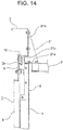
- Figure 14 is a side elevation that shows an elevator cage front surface upper portion according to Embodiment 5 of the present invention.
- a beam bearing portion 21 c that bears a vertically downward load of the beam 2 is disposed on a beam mounting bracket 21.
- the beam bearing portion 21 c is a horizontal portion that is formed by bending an intermediate portion of a vertical portion 21 b.
- the rest of the configuration is similar or identical to that of Embodiment 4.
- the beam bearing portion 21 c is not limited to a bent portion, and may also be a construction in which the beam 2 is engaged or hooked, for example.
- Examples of constructions of this kind include constructions in which an angular aperture is disposed in either one of the beam 2 and the beam mounting bracket 21, and a raised portion of metal plate that is inserted into this angular aperture is disposed on the other, for example.
- Figure 15 is a side elevation that shows an elevator cage front surface upper portion according to Embodiment 6 of the present invention.
- a plurality of adjusting liners 22 that adjust vertical positioning of a beam mounting bracket 21 are interposed between a ceiling 6 and a beam mounting bracket 21.
- the rest of the configuration is similar or identical to that of Embodiment 4.
- adjustment of position of the beam 2 in the depth direction is enabled by making apertures through which bolts that fasten the beam mounting bracket 21 onto the ceiling 6 pass into slots.
- adjustment of the lateral position of the beam 2 is unnecessary due to accurate centering between the ceiling 6 and the center of the car doorway 1 a.
- the adjusting liners 22 may also be interposed between the beam mounting bracket 21 that is shown in Embodiment 5 and the ceiling 6.
- Figure 16 is a side elevation that shows an example of an elevator apparatus to which car constructions according to Embodiments 1 through 6 are applied.
- a pair of car guide rails 32 and a pair of counterweight guide rails 33 are installed inside a hoistway 31.
- a return sheave supporting member 34 is mounted onto upper end portions of the counterweight guide rails 33.
- First and second return sheaves 35 and 36 are mounted onto a return sheave supporting member 34.
- a car 37 that is raised and lowered along the car guide rail 32, and a counterweight 38 that is raised and lowered along the counterweight guide rails 33 are disposed inside the hoistway 31.
- a pair of car suspending sheaves 39 are disposed on a lower portion of the car 37.
- a counterweight suspending sheave 40 is disposed on an upper portion of the counterweight 38.
- a hoisting machine 41 that raises and lowers the car 37 and the counterweight 38 is installed inside the hoistway 31 outside a hoisting zone of the car 37 and the counterweight 38.
- the hoisting machine 41 has: a driving sheave 42; a hoisting machine motor that rotates the driving sheave 42; and a hoisting machine brake that brakes rotation of the driving sheave 42.
- the hoisting machine 41 is supported on a supporting platform 43 that is installed in a bottom portion of the hoistway 31.
- An end portion supporting member 44 is fixed to an upper end portion of the car guide rails 32.
- the car 37 and the counterweight 38 are suspended inside the hoistway 31 by a suspending means 45.
- a plurality of ropes or a plurality of belts are used as the suspending means 45.
- the suspending means 45 has: a first end portion that is connected to the end portion supporting member 44; and a second end portion that is connected to the return sheave supporting member 34.
- the suspending means 45 is wound sequentially from the first end portion side around the car suspending sheaves 39, the first return sheave 35, the driving sheave 42, the second return sheave 36, and the counterweight suspending sheave 40.
- FIG. 16 an elevator apparatus that uses a two-to-one (2:1) roping method is shown, but the roping method is not limited thereto, and the present invention can also be applied to an elevator apparatus that uses a one-to-one (1:1) roping method, for example.
- the overall layout of the elevator apparatus is also not limited to that in Figure 16 , and the hoisting machine 41 may also be disposed in an upper portion of the hoistway, for example.
- an elevator apparatus that does not have a machine room is shown in Figure 16 , but the present invention can also be applied to an elevator apparatus that has a machine room.
- Embodiments 1 through 6 a two-door centrally-opening door apparatus is shown, but the number of car doors 3 is not limited to two, and the present invention can also be applied to a side-opening door apparatus.
Landscapes
- Engineering & Computer Science (AREA)
- Civil Engineering (AREA)
- Mechanical Engineering (AREA)
- Structural Engineering (AREA)
- Cage And Drive Apparatuses For Elevators (AREA)
- Elevator Door Apparatuses (AREA)
- Support Devices For Sliding Doors (AREA)
Priority Applications (1)
| Application Number | Priority Date | Filing Date | Title |
|---|---|---|---|
| EP17191675.2A EP3279129B1 (fr) | 2010-11-22 | 2010-11-22 | Cabine d'ascenseur |
Applications Claiming Priority (3)
| Application Number | Priority Date | Filing Date | Title |
|---|---|---|---|
| EP17191675.2A EP3279129B1 (fr) | 2010-11-22 | 2010-11-22 | Cabine d'ascenseur |
| PCT/JP2010/070794 WO2012070098A1 (fr) | 2010-11-22 | 2010-11-22 | Cabine d'ascenseur |
| EP10860111.3A EP2644811B1 (fr) | 2010-11-22 | 2010-11-22 | Cabine d'ascenseur |
Related Parent Applications (2)
| Application Number | Title | Priority Date | Filing Date |
|---|---|---|---|
| EP10860111.3A Division-Into EP2644811B1 (fr) | 2010-11-22 | 2010-11-22 | Cabine d'ascenseur |
| EP10860111.3A Division EP2644811B1 (fr) | 2010-11-22 | 2010-11-22 | Cabine d'ascenseur |
Publications (2)
| Publication Number | Publication Date |
|---|---|
| EP3279129A1 true EP3279129A1 (fr) | 2018-02-07 |
| EP3279129B1 EP3279129B1 (fr) | 2021-10-27 |
Family
ID=46145475
Family Applications (2)
| Application Number | Title | Priority Date | Filing Date |
|---|---|---|---|
| EP10860111.3A Active EP2644811B1 (fr) | 2010-11-22 | 2010-11-22 | Cabine d'ascenseur |
| EP17191675.2A Active EP3279129B1 (fr) | 2010-11-22 | 2010-11-22 | Cabine d'ascenseur |
Family Applications Before (1)
| Application Number | Title | Priority Date | Filing Date |
|---|---|---|---|
| EP10860111.3A Active EP2644811B1 (fr) | 2010-11-22 | 2010-11-22 | Cabine d'ascenseur |
Country Status (5)
| Country | Link |
|---|---|
| EP (2) | EP2644811B1 (fr) |
| JP (1) | JP5539536B2 (fr) |
| KR (1) | KR101487117B1 (fr) |
| CN (1) | CN103221624B (fr) |
| WO (1) | WO2012070098A1 (fr) |
Families Citing this family (5)
| Publication number | Priority date | Publication date | Assignee | Title |
|---|---|---|---|---|
| JP2016088627A (ja) * | 2014-10-29 | 2016-05-23 | 三菱電機株式会社 | エレベータドアのリニューアル方法 |
| JP6271040B2 (ja) * | 2014-12-05 | 2018-01-31 | 三菱電機株式会社 | エレベータのパネル |
| WO2019038810A1 (fr) * | 2017-08-21 | 2019-02-28 | 三菱電機株式会社 | Dispositif de type châssis de cabine pour ascenseurs |
| WO2021124544A1 (fr) * | 2019-12-20 | 2021-06-24 | 株式会社日立製作所 | Cabine, ascenseur et support de fixation |
| CN115258886B (zh) * | 2022-08-22 | 2024-01-09 | 上海华美电梯装饰有限公司 | 一种电梯用安装板及其生产工艺 |
Citations (5)
| Publication number | Priority date | Publication date | Assignee | Title |
|---|---|---|---|---|
| US2572196A (en) * | 1947-10-01 | 1951-10-23 | Watson Elevator Company | Elevator door operating mechanism |
| US4149615A (en) * | 1977-09-15 | 1979-04-17 | Westinghouse Electric Corp. | Apparatus for mounting an elevator door operator |
| JPS54175141U (fr) | 1978-05-30 | 1979-12-11 | ||
| JPH06329370A (ja) | 1993-05-21 | 1994-11-29 | Mitsubishi Electric Corp | エレベーター用かご |
| US20010047909A1 (en) * | 1996-08-13 | 2001-12-06 | Frank Mollenauer | Support for lift door drive |
Family Cites Families (11)
| Publication number | Priority date | Publication date | Assignee | Title |
|---|---|---|---|---|
| US1925867A (en) * | 1931-11-21 | 1933-09-05 | Westinghouse Elec Elevator Co | Elevator guide-rail supporting device |
| JPS58151183U (ja) * | 1982-04-06 | 1983-10-11 | 三菱電機株式会社 | エレベ−タかごのドア−装置 |
| JPH0237817Y2 (fr) * | 1985-10-16 | 1990-10-12 | ||
| US5612518A (en) * | 1994-04-08 | 1997-03-18 | Otis Elevator Company | Linear induction motor door drive assembly for elevators |
| US5797471A (en) * | 1996-07-19 | 1998-08-25 | Montgomery Kone Inc. | Linear door drive operator |
| DE19745129A1 (de) * | 1997-10-13 | 1999-04-22 | Hydraulik Liftsysteme Walter M | Kabine für einen Aufzug |
| US6082499A (en) * | 1998-08-05 | 2000-07-04 | Vertisys International, Inc. | Wrap-around elevator door |
| US6446762B1 (en) * | 1999-12-16 | 2002-09-10 | Otis Elevator Company | Elevator machine support frame mounted to hoistway wall |
| JP2002211859A (ja) * | 2000-12-22 | 2002-07-31 | Inventio Ag | ドアサスペンションアセンブリ |
| JP2009249155A (ja) * | 2008-04-10 | 2009-10-29 | Mitsubishi Electric Corp | エレベータの戸開閉装置 |
| CN101780912A (zh) * | 2010-02-05 | 2010-07-21 | 苏州易升电梯部件有限公司 | 电梯开门机 |
-
2010
- 2010-11-22 CN CN201080070265.9A patent/CN103221624B/zh active Active
- 2010-11-22 JP JP2012545544A patent/JP5539536B2/ja active Active
- 2010-11-22 EP EP10860111.3A patent/EP2644811B1/fr active Active
- 2010-11-22 KR KR20137016155A patent/KR101487117B1/ko not_active Expired - Fee Related
- 2010-11-22 EP EP17191675.2A patent/EP3279129B1/fr active Active
- 2010-11-22 WO PCT/JP2010/070794 patent/WO2012070098A1/fr not_active Ceased
Patent Citations (5)
| Publication number | Priority date | Publication date | Assignee | Title |
|---|---|---|---|---|
| US2572196A (en) * | 1947-10-01 | 1951-10-23 | Watson Elevator Company | Elevator door operating mechanism |
| US4149615A (en) * | 1977-09-15 | 1979-04-17 | Westinghouse Electric Corp. | Apparatus for mounting an elevator door operator |
| JPS54175141U (fr) | 1978-05-30 | 1979-12-11 | ||
| JPH06329370A (ja) | 1993-05-21 | 1994-11-29 | Mitsubishi Electric Corp | エレベーター用かご |
| US20010047909A1 (en) * | 1996-08-13 | 2001-12-06 | Frank Mollenauer | Support for lift door drive |
Also Published As
| Publication number | Publication date |
|---|---|
| KR20130122643A (ko) | 2013-11-07 |
| JP5539536B2 (ja) | 2014-07-02 |
| CN103221624A (zh) | 2013-07-24 |
| EP2644811A4 (fr) | 2018-01-10 |
| EP3279129B1 (fr) | 2021-10-27 |
| WO2012070098A1 (fr) | 2012-05-31 |
| KR101487117B1 (ko) | 2015-01-28 |
| EP2644811A1 (fr) | 2013-10-02 |
| CN103221624B (zh) | 2015-06-03 |
| EP2644811B1 (fr) | 2018-11-07 |
| JPWO2012070098A1 (ja) | 2014-05-19 |
Similar Documents
| Publication | Publication Date | Title |
|---|---|---|
| EP2361214B1 (fr) | Support de machinerie d'ascenseur | |
| EP2644811B1 (fr) | Cabine d'ascenseur | |
| EP2361211B1 (fr) | Système élévateur comprenant des circuits électroniques de commande portés par un support de machine élévatrice | |
| JP2011121747A (ja) | エレベータのかご | |
| US8793939B2 (en) | Elevator system and installation method | |
| AU2014200928B2 (en) | Door sill unit and method for an elevator landing door unit | |
| EP1329411B1 (fr) | Ascenseur | |
| CN110294392B (zh) | 轿厢门机的安装结构、安装方法及主连接支架、辅连接支架 | |
| WO2021124544A1 (fr) | Cabine, ascenseur et support de fixation | |
| HK1163643B (en) | Elevator system and installation method | |
| HK1163639B (en) | Elevator system including control electronics supported on an elevator machine support | |
| HK1163640B (en) | Elevator machine support | |
| JP2009256084A (ja) | エレベータの乗場装置 |
Legal Events
| Date | Code | Title | Description |
|---|---|---|---|
| PUAI | Public reference made under article 153(3) epc to a published international application that has entered the european phase |
Free format text: ORIGINAL CODE: 0009012 |
|
| STAA | Information on the status of an ep patent application or granted ep patent |
Free format text: STATUS: THE APPLICATION HAS BEEN PUBLISHED |
|
| AC | Divisional application: reference to earlier application |
Ref document number: 2644811 Country of ref document: EP Kind code of ref document: P |
|
| AK | Designated contracting states |
Kind code of ref document: A1 Designated state(s): AL AT BE BG CH CY CZ DE DK EE ES FI FR GB GR HR HU IE IS IT LI LT LU LV MC MK MT NL NO PL PT RO RS SE SI SK SM TR |
|
| STAA | Information on the status of an ep patent application or granted ep patent |
Free format text: STATUS: REQUEST FOR EXAMINATION WAS MADE |
|
| 17P | Request for examination filed |
Effective date: 20180406 |
|
| RBV | Designated contracting states (corrected) |
Designated state(s): AL AT BE BG CH CY CZ DE DK EE ES FI FR GB GR HR HU IE IS IT LI LT LU LV MC MK MT NL NO PL PT RO RS SE SI SK SM TR |
|
| GRAP | Despatch of communication of intention to grant a patent |
Free format text: ORIGINAL CODE: EPIDOSNIGR1 |
|
| STAA | Information on the status of an ep patent application or granted ep patent |
Free format text: STATUS: GRANT OF PATENT IS INTENDED |
|
| INTG | Intention to grant announced |
Effective date: 20210520 |
|
| GRAS | Grant fee paid |
Free format text: ORIGINAL CODE: EPIDOSNIGR3 |
|
| GRAA | (expected) grant |
Free format text: ORIGINAL CODE: 0009210 |
|
| STAA | Information on the status of an ep patent application or granted ep patent |
Free format text: STATUS: THE PATENT HAS BEEN GRANTED |
|
| AC | Divisional application: reference to earlier application |
Ref document number: 2644811 Country of ref document: EP Kind code of ref document: P |
|
| AK | Designated contracting states |
Kind code of ref document: B1 Designated state(s): AL AT BE BG CH CY CZ DE DK EE ES FI FR GB GR HR HU IE IS IT LI LT LU LV MC MK MT NL NO PL PT RO RS SE SI SK SM TR |
|
| REG | Reference to a national code |
Ref country code: GB Ref legal event code: FG4D |
|
| REG | Reference to a national code |
Ref country code: CH Ref legal event code: EP |
|
| REG | Reference to a national code |
Ref country code: AT Ref legal event code: REF Ref document number: 1441622 Country of ref document: AT Kind code of ref document: T Effective date: 20211115 |
|
| REG | Reference to a national code |
Ref country code: DE Ref legal event code: R096 Ref document number: 602010067747 Country of ref document: DE |
|
| REG | Reference to a national code |
Ref country code: IE Ref legal event code: FG4D |
|
| REG | Reference to a national code |
Ref country code: LT Ref legal event code: MG9D |
|
| REG | Reference to a national code |
Ref country code: NL Ref legal event code: MP Effective date: 20211027 |
|
| REG | Reference to a national code |
Ref country code: AT Ref legal event code: MK05 Ref document number: 1441622 Country of ref document: AT Kind code of ref document: T Effective date: 20211027 |
|
| PG25 | Lapsed in a contracting state [announced via postgrant information from national office to epo] |
Ref country code: RS Free format text: LAPSE BECAUSE OF FAILURE TO SUBMIT A TRANSLATION OF THE DESCRIPTION OR TO PAY THE FEE WITHIN THE PRESCRIBED TIME-LIMIT Effective date: 20211027 Ref country code: LT Free format text: LAPSE BECAUSE OF FAILURE TO SUBMIT A TRANSLATION OF THE DESCRIPTION OR TO PAY THE FEE WITHIN THE PRESCRIBED TIME-LIMIT Effective date: 20211027 Ref country code: FI Free format text: LAPSE BECAUSE OF FAILURE TO SUBMIT A TRANSLATION OF THE DESCRIPTION OR TO PAY THE FEE WITHIN THE PRESCRIBED TIME-LIMIT Effective date: 20211027 Ref country code: BG Free format text: LAPSE BECAUSE OF FAILURE TO SUBMIT A TRANSLATION OF THE DESCRIPTION OR TO PAY THE FEE WITHIN THE PRESCRIBED TIME-LIMIT Effective date: 20220127 Ref country code: AT Free format text: LAPSE BECAUSE OF FAILURE TO SUBMIT A TRANSLATION OF THE DESCRIPTION OR TO PAY THE FEE WITHIN THE PRESCRIBED TIME-LIMIT Effective date: 20211027 |
|
| PG25 | Lapsed in a contracting state [announced via postgrant information from national office to epo] |
Ref country code: IS Free format text: LAPSE BECAUSE OF FAILURE TO SUBMIT A TRANSLATION OF THE DESCRIPTION OR TO PAY THE FEE WITHIN THE PRESCRIBED TIME-LIMIT Effective date: 20220227 Ref country code: SE Free format text: LAPSE BECAUSE OF FAILURE TO SUBMIT A TRANSLATION OF THE DESCRIPTION OR TO PAY THE FEE WITHIN THE PRESCRIBED TIME-LIMIT Effective date: 20211027 Ref country code: PT Free format text: LAPSE BECAUSE OF FAILURE TO SUBMIT A TRANSLATION OF THE DESCRIPTION OR TO PAY THE FEE WITHIN THE PRESCRIBED TIME-LIMIT Effective date: 20220228 Ref country code: PL Free format text: LAPSE BECAUSE OF FAILURE TO SUBMIT A TRANSLATION OF THE DESCRIPTION OR TO PAY THE FEE WITHIN THE PRESCRIBED TIME-LIMIT Effective date: 20211027 Ref country code: NO Free format text: LAPSE BECAUSE OF FAILURE TO SUBMIT A TRANSLATION OF THE DESCRIPTION OR TO PAY THE FEE WITHIN THE PRESCRIBED TIME-LIMIT Effective date: 20220127 Ref country code: NL Free format text: LAPSE BECAUSE OF FAILURE TO SUBMIT A TRANSLATION OF THE DESCRIPTION OR TO PAY THE FEE WITHIN THE PRESCRIBED TIME-LIMIT Effective date: 20211027 Ref country code: LV Free format text: LAPSE BECAUSE OF FAILURE TO SUBMIT A TRANSLATION OF THE DESCRIPTION OR TO PAY THE FEE WITHIN THE PRESCRIBED TIME-LIMIT Effective date: 20211027 Ref country code: HR Free format text: LAPSE BECAUSE OF FAILURE TO SUBMIT A TRANSLATION OF THE DESCRIPTION OR TO PAY THE FEE WITHIN THE PRESCRIBED TIME-LIMIT Effective date: 20211027 Ref country code: GR Free format text: LAPSE BECAUSE OF FAILURE TO SUBMIT A TRANSLATION OF THE DESCRIPTION OR TO PAY THE FEE WITHIN THE PRESCRIBED TIME-LIMIT Effective date: 20220128 Ref country code: ES Free format text: LAPSE BECAUSE OF FAILURE TO SUBMIT A TRANSLATION OF THE DESCRIPTION OR TO PAY THE FEE WITHIN THE PRESCRIBED TIME-LIMIT Effective date: 20211027 |
|
| REG | Reference to a national code |
Ref country code: CH Ref legal event code: PL |
|
| REG | Reference to a national code |
Ref country code: DE Ref legal event code: R097 Ref document number: 602010067747 Country of ref document: DE |
|
| PG25 | Lapsed in a contracting state [announced via postgrant information from national office to epo] |
Ref country code: SM Free format text: LAPSE BECAUSE OF FAILURE TO SUBMIT A TRANSLATION OF THE DESCRIPTION OR TO PAY THE FEE WITHIN THE PRESCRIBED TIME-LIMIT Effective date: 20211027 Ref country code: SK Free format text: LAPSE BECAUSE OF FAILURE TO SUBMIT A TRANSLATION OF THE DESCRIPTION OR TO PAY THE FEE WITHIN THE PRESCRIBED TIME-LIMIT Effective date: 20211027 Ref country code: RO Free format text: LAPSE BECAUSE OF FAILURE TO SUBMIT A TRANSLATION OF THE DESCRIPTION OR TO PAY THE FEE WITHIN THE PRESCRIBED TIME-LIMIT Effective date: 20211027 Ref country code: MC Free format text: LAPSE BECAUSE OF FAILURE TO SUBMIT A TRANSLATION OF THE DESCRIPTION OR TO PAY THE FEE WITHIN THE PRESCRIBED TIME-LIMIT Effective date: 20211027 Ref country code: LU Free format text: LAPSE BECAUSE OF NON-PAYMENT OF DUE FEES Effective date: 20211122 Ref country code: EE Free format text: LAPSE BECAUSE OF FAILURE TO SUBMIT A TRANSLATION OF THE DESCRIPTION OR TO PAY THE FEE WITHIN THE PRESCRIBED TIME-LIMIT Effective date: 20211027 Ref country code: DK Free format text: LAPSE BECAUSE OF FAILURE TO SUBMIT A TRANSLATION OF THE DESCRIPTION OR TO PAY THE FEE WITHIN THE PRESCRIBED TIME-LIMIT Effective date: 20211027 Ref country code: CZ Free format text: LAPSE BECAUSE OF FAILURE TO SUBMIT A TRANSLATION OF THE DESCRIPTION OR TO PAY THE FEE WITHIN THE PRESCRIBED TIME-LIMIT Effective date: 20211027 Ref country code: BE Free format text: LAPSE BECAUSE OF NON-PAYMENT OF DUE FEES Effective date: 20211130 |
|
| REG | Reference to a national code |
Ref country code: BE Ref legal event code: MM Effective date: 20211130 |
|
| PLBE | No opposition filed within time limit |
Free format text: ORIGINAL CODE: 0009261 |
|
| STAA | Information on the status of an ep patent application or granted ep patent |
Free format text: STATUS: NO OPPOSITION FILED WITHIN TIME LIMIT |
|
| GBPC | Gb: european patent ceased through non-payment of renewal fee |
Effective date: 20220127 |
|
| 26N | No opposition filed |
Effective date: 20220728 |
|
| PG25 | Lapsed in a contracting state [announced via postgrant information from national office to epo] |
Ref country code: IE Free format text: LAPSE BECAUSE OF NON-PAYMENT OF DUE FEES Effective date: 20211122 Ref country code: GB Free format text: LAPSE BECAUSE OF NON-PAYMENT OF DUE FEES Effective date: 20220127 Ref country code: AL Free format text: LAPSE BECAUSE OF FAILURE TO SUBMIT A TRANSLATION OF THE DESCRIPTION OR TO PAY THE FEE WITHIN THE PRESCRIBED TIME-LIMIT Effective date: 20211027 |
|
| PG25 | Lapsed in a contracting state [announced via postgrant information from national office to epo] |
Ref country code: SI Free format text: LAPSE BECAUSE OF FAILURE TO SUBMIT A TRANSLATION OF THE DESCRIPTION OR TO PAY THE FEE WITHIN THE PRESCRIBED TIME-LIMIT Effective date: 20211027 Ref country code: FR Free format text: LAPSE BECAUSE OF NON-PAYMENT OF DUE FEES Effective date: 20211227 |
|
| PG25 | Lapsed in a contracting state [announced via postgrant information from national office to epo] |
Ref country code: IT Free format text: LAPSE BECAUSE OF FAILURE TO SUBMIT A TRANSLATION OF THE DESCRIPTION OR TO PAY THE FEE WITHIN THE PRESCRIBED TIME-LIMIT Effective date: 20211027 Ref country code: HU Free format text: LAPSE BECAUSE OF FAILURE TO SUBMIT A TRANSLATION OF THE DESCRIPTION OR TO PAY THE FEE WITHIN THE PRESCRIBED TIME-LIMIT; INVALID AB INITIO Effective date: 20101122 Ref country code: CY Free format text: LAPSE BECAUSE OF FAILURE TO SUBMIT A TRANSLATION OF THE DESCRIPTION OR TO PAY THE FEE WITHIN THE PRESCRIBED TIME-LIMIT Effective date: 20211027 |
|
| P01 | Opt-out of the competence of the unified patent court (upc) registered |
Effective date: 20230512 |
|
| PG25 | Lapsed in a contracting state [announced via postgrant information from national office to epo] |
Ref country code: LI Free format text: LAPSE BECAUSE OF NON-PAYMENT OF DUE FEES Effective date: 20220701 Ref country code: CH Free format text: LAPSE BECAUSE OF NON-PAYMENT OF DUE FEES Effective date: 20220701 |
|
| REG | Reference to a national code |
Ref country code: DE Ref legal event code: R084 Ref document number: 602010067747 Country of ref document: DE |
|
| PG25 | Lapsed in a contracting state [announced via postgrant information from national office to epo] |
Ref country code: MK Free format text: LAPSE BECAUSE OF FAILURE TO SUBMIT A TRANSLATION OF THE DESCRIPTION OR TO PAY THE FEE WITHIN THE PRESCRIBED TIME-LIMIT Effective date: 20211027 |
|
| PG25 | Lapsed in a contracting state [announced via postgrant information from national office to epo] |
Ref country code: MT Free format text: LAPSE BECAUSE OF FAILURE TO SUBMIT A TRANSLATION OF THE DESCRIPTION OR TO PAY THE FEE WITHIN THE PRESCRIBED TIME-LIMIT Effective date: 20211027 |
|
| PGFP | Annual fee paid to national office [announced via postgrant information from national office to epo] |
Ref country code: DE Payment date: 20241001 Year of fee payment: 15 |
|
| PG25 | Lapsed in a contracting state [announced via postgrant information from national office to epo] |
Ref country code: TR Free format text: LAPSE BECAUSE OF FAILURE TO SUBMIT A TRANSLATION OF THE DESCRIPTION OR TO PAY THE FEE WITHIN THE PRESCRIBED TIME-LIMIT Effective date: 20211027 |