EP3279568A1 - Hitzeschild für einen gasturbinenmotor - Google Patents
Hitzeschild für einen gasturbinenmotor Download PDFInfo
- Publication number
- EP3279568A1 EP3279568A1 EP17184794.0A EP17184794A EP3279568A1 EP 3279568 A1 EP3279568 A1 EP 3279568A1 EP 17184794 A EP17184794 A EP 17184794A EP 3279568 A1 EP3279568 A1 EP 3279568A1
- Authority
- EP
- European Patent Office
- Prior art keywords
- heat shield
- shield panel
- substrate surface
- combustor
- gas turbine
- Prior art date
- Legal status (The legal status is an assumption and is not a legal conclusion. Google has not performed a legal analysis and makes no representation as to the accuracy of the status listed.)
- Granted
Links
Images



Classifications
-
- F—MECHANICAL ENGINEERING; LIGHTING; HEATING; WEAPONS; BLASTING
- F23—COMBUSTION APPARATUS; COMBUSTION PROCESSES
- F23R—GENERATING COMBUSTION PRODUCTS OF HIGH PRESSURE OR HIGH VELOCITY, e.g. GAS-TURBINE COMBUSTION CHAMBERS
- F23R3/00—Continuous combustion chambers using liquid or gaseous fuel
- F23R3/002—Wall structures
-
- F—MECHANICAL ENGINEERING; LIGHTING; HEATING; WEAPONS; BLASTING
- F02—COMBUSTION ENGINES; HOT-GAS OR COMBUSTION-PRODUCT ENGINE PLANTS
- F02C—GAS-TURBINE PLANTS; AIR INTAKES FOR JET-PROPULSION PLANTS; CONTROLLING FUEL SUPPLY IN AIR-BREATHING JET-PROPULSION PLANTS
- F02C3/00—Gas-turbine plants characterised by the use of combustion products as the working fluid
- F02C3/04—Gas-turbine plants characterised by the use of combustion products as the working fluid having a turbine driving a compressor
-
- F—MECHANICAL ENGINEERING; LIGHTING; HEATING; WEAPONS; BLASTING
- F02—COMBUSTION ENGINES; HOT-GAS OR COMBUSTION-PRODUCT ENGINE PLANTS
- F02C—GAS-TURBINE PLANTS; AIR INTAKES FOR JET-PROPULSION PLANTS; CONTROLLING FUEL SUPPLY IN AIR-BREATHING JET-PROPULSION PLANTS
- F02C7/00—Features, components parts, details or accessories, not provided for in, or of interest apart form groups F02C1/00 - F02C6/00; Air intakes for jet-propulsion plants
- F02C7/24—Heat or noise insulation
-
- F—MECHANICAL ENGINEERING; LIGHTING; HEATING; WEAPONS; BLASTING
- F23—COMBUSTION APPARATUS; COMBUSTION PROCESSES
- F23R—GENERATING COMBUSTION PRODUCTS OF HIGH PRESSURE OR HIGH VELOCITY, e.g. GAS-TURBINE COMBUSTION CHAMBERS
- F23R3/00—Continuous combustion chambers using liquid or gaseous fuel
- F23R3/02—Continuous combustion chambers using liquid or gaseous fuel characterised by the air-flow or gas-flow configuration
- F23R3/04—Air inlet arrangements
- F23R3/06—Arrangement of apertures along the flame tube
-
- F—MECHANICAL ENGINEERING; LIGHTING; HEATING; WEAPONS; BLASTING
- F05—INDEXING SCHEMES RELATING TO ENGINES OR PUMPS IN VARIOUS SUBCLASSES OF CLASSES F01-F04
- F05D—INDEXING SCHEME FOR ASPECTS RELATING TO NON-POSITIVE-DISPLACEMENT MACHINES OR ENGINES, GAS-TURBINES OR JET-PROPULSION PLANTS
- F05D2220/00—Application
- F05D2220/30—Application in turbines
- F05D2220/32—Application in turbines in gas turbines
-
- F—MECHANICAL ENGINEERING; LIGHTING; HEATING; WEAPONS; BLASTING
- F05—INDEXING SCHEMES RELATING TO ENGINES OR PUMPS IN VARIOUS SUBCLASSES OF CLASSES F01-F04
- F05D—INDEXING SCHEME FOR ASPECTS RELATING TO NON-POSITIVE-DISPLACEMENT MACHINES OR ENGINES, GAS-TURBINES OR JET-PROPULSION PLANTS
- F05D2230/00—Manufacture
- F05D2230/90—Coating; Surface treatment
-
- F—MECHANICAL ENGINEERING; LIGHTING; HEATING; WEAPONS; BLASTING
- F05—INDEXING SCHEMES RELATING TO ENGINES OR PUMPS IN VARIOUS SUBCLASSES OF CLASSES F01-F04
- F05D—INDEXING SCHEME FOR ASPECTS RELATING TO NON-POSITIVE-DISPLACEMENT MACHINES OR ENGINES, GAS-TURBINES OR JET-PROPULSION PLANTS
- F05D2240/00—Components
- F05D2240/35—Combustors or associated equipment
-
- F—MECHANICAL ENGINEERING; LIGHTING; HEATING; WEAPONS; BLASTING
- F05—INDEXING SCHEMES RELATING TO ENGINES OR PUMPS IN VARIOUS SUBCLASSES OF CLASSES F01-F04
- F05D—INDEXING SCHEME FOR ASPECTS RELATING TO NON-POSITIVE-DISPLACEMENT MACHINES OR ENGINES, GAS-TURBINES OR JET-PROPULSION PLANTS
- F05D2300/00—Materials; Properties thereof
- F05D2300/10—Metals, alloys or intermetallic compounds
-
- F—MECHANICAL ENGINEERING; LIGHTING; HEATING; WEAPONS; BLASTING
- F05—INDEXING SCHEMES RELATING TO ENGINES OR PUMPS IN VARIOUS SUBCLASSES OF CLASSES F01-F04
- F05D—INDEXING SCHEME FOR ASPECTS RELATING TO NON-POSITIVE-DISPLACEMENT MACHINES OR ENGINES, GAS-TURBINES OR JET-PROPULSION PLANTS
- F05D2300/00—Materials; Properties thereof
- F05D2300/20—Oxide or non-oxide ceramics
-
- F—MECHANICAL ENGINEERING; LIGHTING; HEATING; WEAPONS; BLASTING
- F05—INDEXING SCHEMES RELATING TO ENGINES OR PUMPS IN VARIOUS SUBCLASSES OF CLASSES F01-F04
- F05D—INDEXING SCHEME FOR ASPECTS RELATING TO NON-POSITIVE-DISPLACEMENT MACHINES OR ENGINES, GAS-TURBINES OR JET-PROPULSION PLANTS
- F05D2300/00—Materials; Properties thereof
- F05D2300/60—Properties or characteristics given to material by treatment or manufacturing
- F05D2300/611—Coating
-
- F—MECHANICAL ENGINEERING; LIGHTING; HEATING; WEAPONS; BLASTING
- F23—COMBUSTION APPARATUS; COMBUSTION PROCESSES
- F23R—GENERATING COMBUSTION PRODUCTS OF HIGH PRESSURE OR HIGH VELOCITY, e.g. GAS-TURBINE COMBUSTION CHAMBERS
- F23R2900/00—Special features of, or arrangements for continuous combustion chambers; Combustion processes therefor
- F23R2900/03043—Convection cooled combustion chamber walls with means for guiding the cooling air flow
Definitions
- This disclosure relates to gas turbine engines, and more particularly to combustor panels for a combustor of a gas turbine engine.
- a gas turbine engine typically includes a compressor which compresses and directs an airflow to a combustor. At the combustor, the airflow is mixed with fuel and ignited. Post-combustor, the airflow is utilized to drive a turbine.
- Combustors utilize panels offset from a combustor shell to define cooling pathways to protect itself from the heat of combustion.
- Current combustor panels typical overlap with each other to define a slot through which an airflow can be directed for film cooling of downstream panels.
- the panels are coated with a thermally-protective material which may have a tapered thickness at the ends of the combustor panels to maintain proper assembly fits and clearances, as well as to maintain a desired flow area through the slot.
- Emerging coating systems have advanced microstructure, and cannot be tapered without risk of chipping, spalling, reduced oxidation resistance capability or other negative effects. At the same time, the taper is needed to maintain the assembly fits and clearances and flow area.
- a heat shield panel for a gas turbine engine includes a substrate layer having a first substrate surface and a second substrate surface opposite the first substrate surface.
- the first substrate surface and the second substrate surface define a substrate layer thickness therebetween.
- One or more thermally protective coating layers are applied to the first substrate surface of the substrate layer.
- the one or more coating layers have a constant coating layer thickness and the substrate layer thickness tapers along an axial length of the heat shield panel.
- the substrate layer thickness tapers along a taper length equal to up to 50 percent of a heat shield panel length.
- the taper length is between 10 percent and 40 percent of the heat shield panel length.
- a taper angle between the first substrate surface and the second substrate surface is up to sixty degrees.
- the substrate layer is formed from a metallic material.
- the at least one coating layer of the one or more coating layers are formed from a ceramic material.
- a plurality of heat dissipation features extend from the second substrate surface.
- the plurality of heat dissipation features include one or more of pins or fins.
- a combustor for a gas turbine engine in another embodiment, includes a combustor shell and a plurality of heat shield panels secured to the combustor shell.
- the heat shield panels include a substrate layer having a first substrate surface and a second substrate surface opposite the first substrate surface. The first substrate surface and the second substrate surface define a substrate layer thickness therebetween.
- One or more thermally protective coating layers are applied to the first substrate surface of the substrate layer. The one or more coating layers have a constant coating layer thickness and the substrate layer thickness tapers along an axial length of the heat shield panel.
- a first heat shield panel of the plurality of heat shield panels is tapered at an overlap to a second heat shield panel of the plurality of heat shield panels.
- the overlap defines a flow passage for a cooling airflow.
- the substrate layer thickness tapers along a taper length equal to up to 50 percent of a heat shield panel length.
- the taper length is between 10 percent and 40 percent of the heat shield panel length.
- a taper angle between the first substrate surface and the second substrate surface is up to sixty degrees.
- the substrate layer is formed from a metallic material.
- At least one coating layer of the one or more coating layers are formed from a ceramic material.
- a plurality of heat dissipation features extend from the second substrate surface.
- the plurality of heat dissipation features include one or more of pins or fins.
- a gas turbine engine in yet another embodiment, includes a turbine and a combustor operably connected to the turbine.
- the combustor includes a combustor shell and a plurality of heat shield panels secured to the combustor shell.
- the heat shield panels have a substrate layer with a first substrate surface and a second substrate surface opposite the first substrate surface.
- the first substrate surface and the second substrate surface define a substrate layer thickness therebetween.
- One or more thermally protective coating layers are applied to the first substrate surface of the substrate layer.
- the one or more coating layers have a constant coating layer thickness and the substrate layer thickness tapers along an axial length of the heat shield panel.
- a first heat shield panel of the plurality of heat shield panels is tapered at an overlap to a second heat shield panel of the plurality of heat shield panels.
- FIG. 1 is a schematic illustration of a gas turbine engine 10.
- the gas turbine engine generally has a fan 12 through which ambient air is propelled in the direction of arrow 14, a compressor 16 for pressurizing the air received from the fan 12 and a combustor 18 wherein the compressed air is mixed with fuel and ignited for generating combustion gases.
- the gas turbine engine 10 further comprises a turbine section 20 for extracting energy from the combustion gases. Fuel is injected into the combustor 18 of the gas turbine engine 10 for mixing with the compressed air from the compressor 16 and ignition of the resultant mixture.
- the fan 12, compressor 16, combustor 18, and turbine 20 are typically all concentric about a common central longitudinal axis X of the gas turbine engine 10.
- the gas turbine engine 10 may further comprise a low pressure compressor 22 located upstream of a high pressure compressor 24 and a high pressure turbine located upstream of a low pressure turbine.
- the compressor 16 may be a multi-stage compressor 16 that has a low-pressure compressor 22 and a high-pressure compressor 24 and the turbine 20 may be a multistage turbine 20 that has a high-pressure turbine and a low-pressure turbine.
- the low-pressure compressor 22 is connected to the low-pressure turbine and the high pressure compressor 24 is connected to the high-pressure turbine.
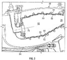
- the combustor 18 generally includes an outer shell 60 and an inner shell 62 within a combustor case 64. It should be understood that various combustor arrangements may alternatively be provided and benefit herefrom.
- the outer shell 60 and the inner shell 62 define a combustion chamber 66 between shells 60, 62.
- Outer and inner shells 60, 62 extend toward the turbine section 20.
- a multiple of heat shield panels 68 line the hot side of the outer shell 60 and the inner shell 62.
- hot side refers to a surface substantially facing a combustion chamber axis 74, as opposed to “cold side”, which refers to a surface substantially facing away from the combustion chamber axis 74.
- Fastener assemblies F such as studs and nuts may be used to connect each of the heat shield panels 68 to the respective inner and outer shells 60, 62.
- the heat shield panels 68 define an array which may be generally annular in shape and extend toward the turbine section 28. Impingement cooling holes (not shown) penetrate through the inner and outer support shells 60, 62 to communicate coolant, such as secondary cooling air, into the space between the inner and outer support shells 60, 62 and the heat shield panels 68.
- the heat shield panels 68 each include a first panel surface 76 substantially facing the combustion chamber axis 74 and a second panel surface 78 opposite the first panel surface 76 and substantially facing the respective inner or outer shell 60, 62 to which it is secured.
- the heat shield panels 68 further include heat dissipation features 80, such as pins and/or fins extending from the second panel surface 78 to dissipate thermal energy from the heat shield panels 68 via the secondary cooling air flowing between the heat shield panels 68 and the inner and outer shells 60, 62.
- film cooling is utilized to thermally protect the heat shield panels 68 from the heat of the combustion chamber 66.
- the heat shield panels 68 are shingled or overlapped defining a flow passage 82 between adjacent heat shield panels 68.
- a portion of the secondary cooling flow 84 passes through the flow passage 82 and along the first panel surface 76 to define a cooling film along a downstream panel surface 76.
- the heat shield panels 68 include a substrate layer 86 manufactured of, for example, a nickel based superalloy.
- the heat shield panels 68 further include a coating layer 88 that defines the first panel surface 76 of the heat shield panel 68.
- the coating layer 88 a thermally protective layer which in some embodiments is formed from, for example, a ceramic material. Such coatings have advanced microstructure, so it is desired to apply the coating layer 88 as a constant thickness layer to the substrate layer 86.
- coating layer 88 may comprise a plurality of coating layers 88, each with a constant thickness.
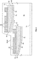
- the heat shield panel 68 (including both the substrate layer 86 and the coating layer 88) has a tapered thickness, at least at an overlap portion 90 (shown best in FIG. 4 ), where the heat shield panel 68 overlaps an adjacent heat shield panel 68.
- the tapered thickness is utilized to maintain assembly fits and clearances between the adjacent heat shield panels 68 and to ensure the flow passage 82 cross-sectional area is maintained within a selected range.
- the tapered heat shield panel thickness 94 is achieved by tapering a substrate layer thickness 96.
- the substrate layer thickness 96 is defined by a taper length 98 a taper depth 100 and/or a taper angle 102.
- the taper length 98 is up to 50% of a panel length 104 of the heat shield panel 68. Further, in other embodiments, the taper length 98 is between 10% and 40% of the panel length 104.
- the taper angle 102 is up to about 60 degrees.
- Tapering of the substrate layer 86 as in the present disclosure defines a taper of the heat shield panel 68 to maintain proper assembly fits and clearances, as well as to maintain a desired flow area through the flow passage 82. It further allows the coating layer 88 to be applied at a constant thickness, without taper, to reduce risk of chipping, spalling, reduced oxidation resistance capability or other negative effects to the coating layer 88 and/or the substrate layer 86.
- heat shield panels 68 are applied herein to the combustor 56, one skilled in the art will readily appreciate that the present disclosure may be applied overlapping panels utilized in other portions of the gas turbine engine 10, for example, an augmenter or exit nozzle portion of the gas turbine engine 10 where panels may be utilized to thermally insulate components as well as reduce observable signature of the components.
Landscapes
- Engineering & Computer Science (AREA)
- Chemical & Material Sciences (AREA)
- Combustion & Propulsion (AREA)
- Mechanical Engineering (AREA)
- General Engineering & Computer Science (AREA)
- Turbine Rotor Nozzle Sealing (AREA)
Applications Claiming Priority (1)
| Application Number | Priority Date | Filing Date | Title |
|---|---|---|---|
| US15/228,029 US10684014B2 (en) | 2016-08-04 | 2016-08-04 | Combustor panel for gas turbine engine |
Publications (3)
| Publication Number | Publication Date |
|---|---|
| EP3279568A1 true EP3279568A1 (de) | 2018-02-07 |
| EP3279568B1 EP3279568B1 (de) | 2021-02-24 |
| EP3279568B8 EP3279568B8 (de) | 2021-03-31 |
Family
ID=59699463
Family Applications (1)
| Application Number | Title | Priority Date | Filing Date |
|---|---|---|---|
| EP17184794.0A Active EP3279568B8 (de) | 2016-08-04 | 2017-08-03 | Brennkammer für einen gasturbinenmotor |
Country Status (2)
| Country | Link |
|---|---|
| US (1) | US10684014B2 (de) |
| EP (1) | EP3279568B8 (de) |
Cited By (4)
| Publication number | Priority date | Publication date | Assignee | Title |
|---|---|---|---|---|
| US10655853B2 (en) | 2016-11-10 | 2020-05-19 | United Technologies Corporation | Combustor liner panel with non-linear circumferential edge for a gas turbine engine combustor |
| EP3321585B1 (de) * | 2016-11-10 | 2020-07-22 | United Technologies Corporation | Nichtplanare brennkammerverkleidungsplatte für eine gasturbinenmotorbrennkammer |
| US10830433B2 (en) | 2016-11-10 | 2020-11-10 | Raytheon Technologies Corporation | Axial non-linear interface for combustor liner panels in a gas turbine combustor |
| US10935236B2 (en) | 2016-11-10 | 2021-03-02 | Raytheon Technologies Corporation | Non-planar combustor liner panel for a gas turbine engine combustor |
Families Citing this family (3)
| Publication number | Priority date | Publication date | Assignee | Title |
|---|---|---|---|---|
| US10408451B2 (en) * | 2013-09-11 | 2019-09-10 | Siemens Aktiengesellschaft | Wedge-shaped ceramic heat shield of a gas turbine combustion chamber |
| US10247106B2 (en) * | 2016-06-15 | 2019-04-02 | General Electric Company | Method and system for rotating air seal with integral flexible heat shield |
| US10386067B2 (en) * | 2016-09-15 | 2019-08-20 | United Technologies Corporation | Wall panel assembly for a gas turbine engine |
Citations (12)
| Publication number | Priority date | Publication date | Assignee | Title |
|---|---|---|---|---|
| EP0136071A1 (de) * | 1983-08-26 | 1985-04-03 | Westinghouse Electric Corporation | Thermische Schutzschicht von variabler Dicke für eine Gasturbinenbrennkammer |
| EP0150656A1 (de) * | 1983-12-21 | 1985-08-07 | United Technologies Corporation | Brennkammerwand mit Überzug für hohe Temperatur |
| US5439348A (en) * | 1994-03-30 | 1995-08-08 | United Technologies Corporation | Turbine shroud segment including a coating layer having varying thickness |
| EP1104872A1 (de) * | 1999-12-03 | 2001-06-06 | General Electric Company | Verfahren zur Verminderung der Wärmebelastung einer Brennkammerwand |
| GB2368902A (en) * | 2000-11-11 | 2002-05-15 | Rolls Royce Plc | A double wall combustor arrangement |
| US20020124572A1 (en) * | 2001-03-12 | 2002-09-12 | Anthony Pidcock | Combustion apparatus |
| EP1515090A1 (de) * | 2003-09-10 | 2005-03-16 | General Electric Company | Brennkammerwand mit dicker Beschichtung |
| GB2441342A (en) * | 2006-09-01 | 2008-03-05 | Rolls Royce Plc | Wall Elements for Gas Turbine Engine Components |
| US20100011775A1 (en) * | 2008-07-17 | 2010-01-21 | Rolls-Royce Plc | Combustion apparatus |
| WO2015036430A1 (de) * | 2013-09-11 | 2015-03-19 | Siemens Aktiengesellschaft | Keilförmiges keramisches hitzeschild einer gasturbinenbrennkammer |
| EP3032175A1 (de) * | 2014-12-12 | 2016-06-15 | United Technologies Corporation | Gekühlte wandanordnung für eine brennkammer und verfahren zum entwurf |
| WO2016099805A2 (en) * | 2014-11-21 | 2016-06-23 | General Electric Technology Gmbh | Flamesheet combustor contoured liner |
Family Cites Families (8)
| Publication number | Priority date | Publication date | Assignee | Title |
|---|---|---|---|---|
| FR2644209B1 (fr) * | 1989-03-08 | 1991-05-03 | Snecma | Chemise de protection thermique pour canal chaud de turboreacteur |
| US5419681A (en) * | 1993-01-25 | 1995-05-30 | General Electric Company | Film cooled wall |
| DE102004029696A1 (de) * | 2004-06-15 | 2006-01-05 | Rolls-Royce Deutschland Ltd & Co Kg | Plattformkühlanordnung für den Leitschaufelkranz einer Gasturbine |
| US8243891B2 (en) * | 2005-01-28 | 2012-08-14 | Value-Added Communications, Inc. | Voice message exchange |
| US7546737B2 (en) * | 2006-01-24 | 2009-06-16 | Honeywell International Inc. | Segmented effusion cooled gas turbine engine combustor |
| US7856830B2 (en) * | 2006-05-26 | 2010-12-28 | Pratt & Whitney Canada Corp. | Noise reducing combustor |
| US20120073303A1 (en) * | 2010-09-23 | 2012-03-29 | General Electric Company | Metal injection molding process and components formed therewith |
| US9410702B2 (en) * | 2014-02-10 | 2016-08-09 | Honeywell International Inc. | Gas turbine engine combustors with effusion and impingement cooling and methods for manufacturing the same using additive manufacturing techniques |
-
2016
- 2016-08-04 US US15/228,029 patent/US10684014B2/en active Active
-
2017
- 2017-08-03 EP EP17184794.0A patent/EP3279568B8/de active Active
Patent Citations (12)
| Publication number | Priority date | Publication date | Assignee | Title |
|---|---|---|---|---|
| EP0136071A1 (de) * | 1983-08-26 | 1985-04-03 | Westinghouse Electric Corporation | Thermische Schutzschicht von variabler Dicke für eine Gasturbinenbrennkammer |
| EP0150656A1 (de) * | 1983-12-21 | 1985-08-07 | United Technologies Corporation | Brennkammerwand mit Überzug für hohe Temperatur |
| US5439348A (en) * | 1994-03-30 | 1995-08-08 | United Technologies Corporation | Turbine shroud segment including a coating layer having varying thickness |
| EP1104872A1 (de) * | 1999-12-03 | 2001-06-06 | General Electric Company | Verfahren zur Verminderung der Wärmebelastung einer Brennkammerwand |
| GB2368902A (en) * | 2000-11-11 | 2002-05-15 | Rolls Royce Plc | A double wall combustor arrangement |
| US20020124572A1 (en) * | 2001-03-12 | 2002-09-12 | Anthony Pidcock | Combustion apparatus |
| EP1515090A1 (de) * | 2003-09-10 | 2005-03-16 | General Electric Company | Brennkammerwand mit dicker Beschichtung |
| GB2441342A (en) * | 2006-09-01 | 2008-03-05 | Rolls Royce Plc | Wall Elements for Gas Turbine Engine Components |
| US20100011775A1 (en) * | 2008-07-17 | 2010-01-21 | Rolls-Royce Plc | Combustion apparatus |
| WO2015036430A1 (de) * | 2013-09-11 | 2015-03-19 | Siemens Aktiengesellschaft | Keilförmiges keramisches hitzeschild einer gasturbinenbrennkammer |
| WO2016099805A2 (en) * | 2014-11-21 | 2016-06-23 | General Electric Technology Gmbh | Flamesheet combustor contoured liner |
| EP3032175A1 (de) * | 2014-12-12 | 2016-06-15 | United Technologies Corporation | Gekühlte wandanordnung für eine brennkammer und verfahren zum entwurf |
Cited By (5)
| Publication number | Priority date | Publication date | Assignee | Title |
|---|---|---|---|---|
| US10655853B2 (en) | 2016-11-10 | 2020-05-19 | United Technologies Corporation | Combustor liner panel with non-linear circumferential edge for a gas turbine engine combustor |
| EP3321585B1 (de) * | 2016-11-10 | 2020-07-22 | United Technologies Corporation | Nichtplanare brennkammerverkleidungsplatte für eine gasturbinenmotorbrennkammer |
| US10830433B2 (en) | 2016-11-10 | 2020-11-10 | Raytheon Technologies Corporation | Axial non-linear interface for combustor liner panels in a gas turbine combustor |
| US10935235B2 (en) | 2016-11-10 | 2021-03-02 | Raytheon Technologies Corporation | Non-planar combustor liner panel for a gas turbine engine combustor |
| US10935236B2 (en) | 2016-11-10 | 2021-03-02 | Raytheon Technologies Corporation | Non-planar combustor liner panel for a gas turbine engine combustor |
Also Published As
| Publication number | Publication date |
|---|---|
| US10684014B2 (en) | 2020-06-16 |
| US20180038593A1 (en) | 2018-02-08 |
| EP3279568B1 (de) | 2021-02-24 |
| EP3279568B8 (de) | 2021-03-31 |
Similar Documents
| Publication | Publication Date | Title |
|---|---|---|
| EP3279568B1 (de) | Brennkammer für einen gasturbinenmotor | |
| US7836703B2 (en) | Reciprocal cooled turbine nozzle | |
| EP2900969B1 (de) | Trennwandanordnung für brennkammer | |
| US7386980B2 (en) | Combustion liner with enhanced heat transfer | |
| US10041676B2 (en) | Sealed conical-flat dome for flight engine combustors | |
| EP3008387B1 (de) | Oberflächenkühlungsverstärkung für eine gasturbinenbrennkammer durch eine leitfähige platte | |
| US10352566B2 (en) | Gas turbine engine combustor liner panel | |
| US10317080B2 (en) | Co-swirl orientation of combustor effusion passages for gas turbine engine combustor | |
| EP3438537B1 (de) | Brennkammerauskleidungsplatte mit einer vielzahl von wärmeübertragungsrippen für eine gasturbinenbrennkammer | |
| EP3026343B1 (de) | Selbstkühlende düsenstruktur | |
| US20160123592A1 (en) | Gas turbine engine combustor liner panel | |
| US20160245094A1 (en) | Engine component | |
| US20080134682A1 (en) | Combustion chamber air inlet | |
| US10655855B2 (en) | Gas turbine engine wall assembly with support shell contour regions | |
| US10024169B2 (en) | Engine component | |
| US10816201B2 (en) | Sealed combustor liner panel for a gas turbine engine | |
| US10508808B2 (en) | Gas turbine engine wave geometry combustor liner panel | |
| US10704424B2 (en) | Coated cooling passage | |
| US20170003027A1 (en) | Gas turbine engine combustor liner panel with synergistic cooling features | |
| US20180230602A1 (en) | Coated combustor panel shell for a gas turbine engine combustor | |
| US20080145211A1 (en) | Wall elements for gas turbine engine components | |
| US10851996B2 (en) | Turbulators for cooling heat shield of a combustor | |
| US20170175532A1 (en) | Angled heat transfer pedestal | |
| US10823410B2 (en) | Cast combustor liner panel radius for gas turbine engine combustor |
Legal Events
| Date | Code | Title | Description |
|---|---|---|---|
| PUAI | Public reference made under article 153(3) epc to a published international application that has entered the european phase |
Free format text: ORIGINAL CODE: 0009012 |
|
| STAA | Information on the status of an ep patent application or granted ep patent |
Free format text: STATUS: THE APPLICATION HAS BEEN PUBLISHED |
|
| AK | Designated contracting states |
Kind code of ref document: A1 Designated state(s): AL AT BE BG CH CY CZ DE DK EE ES FI FR GB GR HR HU IE IS IT LI LT LU LV MC MK MT NL NO PL PT RO RS SE SI SK SM TR |
|
| AX | Request for extension of the european patent |
Extension state: BA ME |
|
| STAA | Information on the status of an ep patent application or granted ep patent |
Free format text: STATUS: REQUEST FOR EXAMINATION WAS MADE |
|
| 17P | Request for examination filed |
Effective date: 20180807 |
|
| RBV | Designated contracting states (corrected) |
Designated state(s): AL AT BE BG CH CY CZ DE DK EE ES FI FR GB GR HR HU IE IS IT LI LT LU LV MC MK MT NL NO PL PT RO RS SE SI SK SM TR |
|
| GRAP | Despatch of communication of intention to grant a patent |
Free format text: ORIGINAL CODE: EPIDOSNIGR1 |
|
| STAA | Information on the status of an ep patent application or granted ep patent |
Free format text: STATUS: GRANT OF PATENT IS INTENDED |
|
| INTG | Intention to grant announced |
Effective date: 20200218 |
|
| GRAJ | Information related to disapproval of communication of intention to grant by the applicant or resumption of examination proceedings by the epo deleted |
Free format text: ORIGINAL CODE: EPIDOSDIGR1 |
|
| STAA | Information on the status of an ep patent application or granted ep patent |
Free format text: STATUS: REQUEST FOR EXAMINATION WAS MADE |
|
| INTC | Intention to grant announced (deleted) | ||
| GRAJ | Information related to disapproval of communication of intention to grant by the applicant or resumption of examination proceedings by the epo deleted |
Free format text: ORIGINAL CODE: EPIDOSDIGR1 |
|
| STAA | Information on the status of an ep patent application or granted ep patent |
Free format text: STATUS: GRANT OF PATENT IS INTENDED |
|
| GRAP | Despatch of communication of intention to grant a patent |
Free format text: ORIGINAL CODE: EPIDOSNIGR1 |
|
| INTG | Intention to grant announced |
Effective date: 20200908 |
|
| RIN1 | Information on inventor provided before grant (corrected) |
Inventor name: BUTLER, AARON S. Inventor name: TU, JOHN S. Inventor name: WERKHEISER, WILLIAM F. Inventor name: TOMEO, KAITLIN M. Inventor name: SERRA, JESSICA L. Inventor name: QUACH, SAN Inventor name: HAZEL, BRIAN T. Inventor name: SELINSKY, ROBERT, JR |
|
| GRAS | Grant fee paid |
Free format text: ORIGINAL CODE: EPIDOSNIGR3 |
|
| GRAA | (expected) grant |
Free format text: ORIGINAL CODE: 0009210 |
|
| STAA | Information on the status of an ep patent application or granted ep patent |
Free format text: STATUS: THE PATENT HAS BEEN GRANTED |
|
| AK | Designated contracting states |
Kind code of ref document: B1 Designated state(s): AL AT BE BG CH CY CZ DE DK EE ES FI FR GB GR HR HU IE IS IT LI LT LU LV MC MK MT NL NO PL PT RO RS SE SI SK SM TR |
|
| REG | Reference to a national code |
Ref country code: CH Ref legal event code: EP |
|
| REG | Reference to a national code |
Ref country code: DE Ref legal event code: R081 Ref document number: 602017033105 Country of ref document: DE Owner name: RAYTHEON TECHNOLOGIES CORPORATION, FARMINGTON, US Free format text: FORMER OWNER: UNITED TECHNOLOGIES CORPORATION, FARMINGTON, CONN., US |
|
| REG | Reference to a national code |
Ref country code: DE Ref legal event code: R096 Ref document number: 602017033105 Country of ref document: DE |
|
| REG | Reference to a national code |
Ref country code: AT Ref legal event code: REF Ref document number: 1364927 Country of ref document: AT Kind code of ref document: T Effective date: 20210315 Ref country code: CH Ref legal event code: PK Free format text: BERICHTIGUNG B8 |
|
| REG | Reference to a national code |
Ref country code: IE Ref legal event code: FG4D |
|
| RAP2 | Party data changed (patent owner data changed or rights of a patent transferred) |
Owner name: RAYTHEON TECHNOLOGIES CORPORATION |
|
| REG | Reference to a national code |
Ref country code: LT Ref legal event code: MG9D |
|
| REG | Reference to a national code |
Ref country code: NL Ref legal event code: MP Effective date: 20210224 |
|
| PG25 | Lapsed in a contracting state [announced via postgrant information from national office to epo] |
Ref country code: BG Free format text: LAPSE BECAUSE OF FAILURE TO SUBMIT A TRANSLATION OF THE DESCRIPTION OR TO PAY THE FEE WITHIN THE PRESCRIBED TIME-LIMIT Effective date: 20210524 Ref country code: LT Free format text: LAPSE BECAUSE OF FAILURE TO SUBMIT A TRANSLATION OF THE DESCRIPTION OR TO PAY THE FEE WITHIN THE PRESCRIBED TIME-LIMIT Effective date: 20210224 Ref country code: GR Free format text: LAPSE BECAUSE OF FAILURE TO SUBMIT A TRANSLATION OF THE DESCRIPTION OR TO PAY THE FEE WITHIN THE PRESCRIBED TIME-LIMIT Effective date: 20210525 Ref country code: FI Free format text: LAPSE BECAUSE OF FAILURE TO SUBMIT A TRANSLATION OF THE DESCRIPTION OR TO PAY THE FEE WITHIN THE PRESCRIBED TIME-LIMIT Effective date: 20210224 Ref country code: HR Free format text: LAPSE BECAUSE OF FAILURE TO SUBMIT A TRANSLATION OF THE DESCRIPTION OR TO PAY THE FEE WITHIN THE PRESCRIBED TIME-LIMIT Effective date: 20210224 Ref country code: PT Free format text: LAPSE BECAUSE OF FAILURE TO SUBMIT A TRANSLATION OF THE DESCRIPTION OR TO PAY THE FEE WITHIN THE PRESCRIBED TIME-LIMIT Effective date: 20210624 Ref country code: NO Free format text: LAPSE BECAUSE OF FAILURE TO SUBMIT A TRANSLATION OF THE DESCRIPTION OR TO PAY THE FEE WITHIN THE PRESCRIBED TIME-LIMIT Effective date: 20210524 |
|
| REG | Reference to a national code |
Ref country code: AT Ref legal event code: MK05 Ref document number: 1364927 Country of ref document: AT Kind code of ref document: T Effective date: 20210224 |
|
| PG25 | Lapsed in a contracting state [announced via postgrant information from national office to epo] |
Ref country code: SE Free format text: LAPSE BECAUSE OF FAILURE TO SUBMIT A TRANSLATION OF THE DESCRIPTION OR TO PAY THE FEE WITHIN THE PRESCRIBED TIME-LIMIT Effective date: 20210224 Ref country code: PL Free format text: LAPSE BECAUSE OF FAILURE TO SUBMIT A TRANSLATION OF THE DESCRIPTION OR TO PAY THE FEE WITHIN THE PRESCRIBED TIME-LIMIT Effective date: 20210224 Ref country code: LV Free format text: LAPSE BECAUSE OF FAILURE TO SUBMIT A TRANSLATION OF THE DESCRIPTION OR TO PAY THE FEE WITHIN THE PRESCRIBED TIME-LIMIT Effective date: 20210224 Ref country code: RS Free format text: LAPSE BECAUSE OF FAILURE TO SUBMIT A TRANSLATION OF THE DESCRIPTION OR TO PAY THE FEE WITHIN THE PRESCRIBED TIME-LIMIT Effective date: 20210224 Ref country code: NL Free format text: LAPSE BECAUSE OF FAILURE TO SUBMIT A TRANSLATION OF THE DESCRIPTION OR TO PAY THE FEE WITHIN THE PRESCRIBED TIME-LIMIT Effective date: 20210224 |
|
| PG25 | Lapsed in a contracting state [announced via postgrant information from national office to epo] |
Ref country code: IS Free format text: LAPSE BECAUSE OF FAILURE TO SUBMIT A TRANSLATION OF THE DESCRIPTION OR TO PAY THE FEE WITHIN THE PRESCRIBED TIME-LIMIT Effective date: 20210624 |
|
| PG25 | Lapsed in a contracting state [announced via postgrant information from national office to epo] |
Ref country code: SM Free format text: LAPSE BECAUSE OF FAILURE TO SUBMIT A TRANSLATION OF THE DESCRIPTION OR TO PAY THE FEE WITHIN THE PRESCRIBED TIME-LIMIT Effective date: 20210224 Ref country code: AT Free format text: LAPSE BECAUSE OF FAILURE TO SUBMIT A TRANSLATION OF THE DESCRIPTION OR TO PAY THE FEE WITHIN THE PRESCRIBED TIME-LIMIT Effective date: 20210224 Ref country code: CZ Free format text: LAPSE BECAUSE OF FAILURE TO SUBMIT A TRANSLATION OF THE DESCRIPTION OR TO PAY THE FEE WITHIN THE PRESCRIBED TIME-LIMIT Effective date: 20210224 Ref country code: EE Free format text: LAPSE BECAUSE OF FAILURE TO SUBMIT A TRANSLATION OF THE DESCRIPTION OR TO PAY THE FEE WITHIN THE PRESCRIBED TIME-LIMIT Effective date: 20210224 |
|
| REG | Reference to a national code |
Ref country code: DE Ref legal event code: R097 Ref document number: 602017033105 Country of ref document: DE |
|
| PG25 | Lapsed in a contracting state [announced via postgrant information from national office to epo] |
Ref country code: SK Free format text: LAPSE BECAUSE OF FAILURE TO SUBMIT A TRANSLATION OF THE DESCRIPTION OR TO PAY THE FEE WITHIN THE PRESCRIBED TIME-LIMIT Effective date: 20210224 Ref country code: RO Free format text: LAPSE BECAUSE OF FAILURE TO SUBMIT A TRANSLATION OF THE DESCRIPTION OR TO PAY THE FEE WITHIN THE PRESCRIBED TIME-LIMIT Effective date: 20210224 Ref country code: DK Free format text: LAPSE BECAUSE OF FAILURE TO SUBMIT A TRANSLATION OF THE DESCRIPTION OR TO PAY THE FEE WITHIN THE PRESCRIBED TIME-LIMIT Effective date: 20210224 |
|
| PLBE | No opposition filed within time limit |
Free format text: ORIGINAL CODE: 0009261 |
|
| STAA | Information on the status of an ep patent application or granted ep patent |
Free format text: STATUS: NO OPPOSITION FILED WITHIN TIME LIMIT |
|
| PG25 | Lapsed in a contracting state [announced via postgrant information from national office to epo] |
Ref country code: AL Free format text: LAPSE BECAUSE OF FAILURE TO SUBMIT A TRANSLATION OF THE DESCRIPTION OR TO PAY THE FEE WITHIN THE PRESCRIBED TIME-LIMIT Effective date: 20210224 Ref country code: ES Free format text: LAPSE BECAUSE OF FAILURE TO SUBMIT A TRANSLATION OF THE DESCRIPTION OR TO PAY THE FEE WITHIN THE PRESCRIBED TIME-LIMIT Effective date: 20210224 |
|
| 26N | No opposition filed |
Effective date: 20211125 |
|
| PG25 | Lapsed in a contracting state [announced via postgrant information from national office to epo] |
Ref country code: SI Free format text: LAPSE BECAUSE OF FAILURE TO SUBMIT A TRANSLATION OF THE DESCRIPTION OR TO PAY THE FEE WITHIN THE PRESCRIBED TIME-LIMIT Effective date: 20210224 |
|
| REG | Reference to a national code |
Ref country code: DE Ref legal event code: R119 Ref document number: 602017033105 Country of ref document: DE |
|
| REG | Reference to a national code |
Ref country code: CH Ref legal event code: PL |
|
| PG25 | Lapsed in a contracting state [announced via postgrant information from national office to epo] |
Ref country code: MC Free format text: LAPSE BECAUSE OF FAILURE TO SUBMIT A TRANSLATION OF THE DESCRIPTION OR TO PAY THE FEE WITHIN THE PRESCRIBED TIME-LIMIT Effective date: 20210224 |
|
| REG | Reference to a national code |
Ref country code: BE Ref legal event code: MM Effective date: 20210831 |
|
| PG25 | Lapsed in a contracting state [announced via postgrant information from national office to epo] |
Ref country code: LI Free format text: LAPSE BECAUSE OF NON-PAYMENT OF DUE FEES Effective date: 20210831 Ref country code: IT Free format text: LAPSE BECAUSE OF FAILURE TO SUBMIT A TRANSLATION OF THE DESCRIPTION OR TO PAY THE FEE WITHIN THE PRESCRIBED TIME-LIMIT Effective date: 20210224 Ref country code: CH Free format text: LAPSE BECAUSE OF NON-PAYMENT OF DUE FEES Effective date: 20210831 |
|
| PG25 | Lapsed in a contracting state [announced via postgrant information from national office to epo] |
Ref country code: IS Free format text: LAPSE BECAUSE OF FAILURE TO SUBMIT A TRANSLATION OF THE DESCRIPTION OR TO PAY THE FEE WITHIN THE PRESCRIBED TIME-LIMIT Effective date: 20210624 Ref country code: LU Free format text: LAPSE BECAUSE OF NON-PAYMENT OF DUE FEES Effective date: 20210803 |
|
| PG25 | Lapsed in a contracting state [announced via postgrant information from national office to epo] |
Ref country code: IE Free format text: LAPSE BECAUSE OF NON-PAYMENT OF DUE FEES Effective date: 20210803 Ref country code: FR Free format text: LAPSE BECAUSE OF NON-PAYMENT OF DUE FEES Effective date: 20210831 Ref country code: DE Free format text: LAPSE BECAUSE OF NON-PAYMENT OF DUE FEES Effective date: 20220301 Ref country code: BE Free format text: LAPSE BECAUSE OF NON-PAYMENT OF DUE FEES Effective date: 20210831 |
|
| PG25 | Lapsed in a contracting state [announced via postgrant information from national office to epo] |
Ref country code: HU Free format text: LAPSE BECAUSE OF FAILURE TO SUBMIT A TRANSLATION OF THE DESCRIPTION OR TO PAY THE FEE WITHIN THE PRESCRIBED TIME-LIMIT; INVALID AB INITIO Effective date: 20170803 |
|
| PG25 | Lapsed in a contracting state [announced via postgrant information from national office to epo] |
Ref country code: CY Free format text: LAPSE BECAUSE OF FAILURE TO SUBMIT A TRANSLATION OF THE DESCRIPTION OR TO PAY THE FEE WITHIN THE PRESCRIBED TIME-LIMIT Effective date: 20210224 |
|
| PG25 | Lapsed in a contracting state [announced via postgrant information from national office to epo] |
Ref country code: MK Free format text: LAPSE BECAUSE OF FAILURE TO SUBMIT A TRANSLATION OF THE DESCRIPTION OR TO PAY THE FEE WITHIN THE PRESCRIBED TIME-LIMIT Effective date: 20210224 |
|
| PG25 | Lapsed in a contracting state [announced via postgrant information from national office to epo] |
Ref country code: MT Free format text: LAPSE BECAUSE OF FAILURE TO SUBMIT A TRANSLATION OF THE DESCRIPTION OR TO PAY THE FEE WITHIN THE PRESCRIBED TIME-LIMIT Effective date: 20210224 |
|
| PGFP | Annual fee paid to national office [announced via postgrant information from national office to epo] |
Ref country code: GB Payment date: 20250724 Year of fee payment: 9 |
|
| PG25 | Lapsed in a contracting state [announced via postgrant information from national office to epo] |
Ref country code: TR Free format text: LAPSE BECAUSE OF FAILURE TO SUBMIT A TRANSLATION OF THE DESCRIPTION OR TO PAY THE FEE WITHIN THE PRESCRIBED TIME-LIMIT Effective date: 20210224 |
|
| P01 | Opt-out of the competence of the unified patent court (upc) registered |
Free format text: CASE NUMBER: UPC_APP_0018347_3279568/2025 Effective date: 20251218 |