EP3279687B1 - Procédé, dispositif et système de suivi d'un signal de faisceau - Google Patents
Procédé, dispositif et système de suivi d'un signal de faisceau Download PDFInfo
- Publication number
- EP3279687B1 EP3279687B1 EP15892878.8A EP15892878A EP3279687B1 EP 3279687 B1 EP3279687 B1 EP 3279687B1 EP 15892878 A EP15892878 A EP 15892878A EP 3279687 B1 EP3279687 B1 EP 3279687B1
- Authority
- EP
- European Patent Office
- Prior art keywords
- frequency shift
- doppler frequency
- receive
- scanning
- change speed
- Prior art date
- Legal status (The legal status is an assumption and is not a legal conclusion. Google has not performed a legal analysis and makes no representation as to the accuracy of the status listed.)
- Active
Links
Images


Classifications
-
- H—ELECTRICITY
- H01—ELECTRIC ELEMENTS
- H01Q—ANTENNAS, i.e. RADIO AERIALS
- H01Q3/00—Arrangements for changing or varying the orientation or the shape of the directional pattern of the waves radiated from an antenna or antenna system
- H01Q3/26—Arrangements for changing or varying the orientation or the shape of the directional pattern of the waves radiated from an antenna or antenna system varying the relative phase or relative amplitude of energisation between two or more active radiating elements; varying the distribution of energy across a radiating aperture
- H01Q3/30—Arrangements for changing or varying the orientation or the shape of the directional pattern of the waves radiated from an antenna or antenna system varying the relative phase or relative amplitude of energisation between two or more active radiating elements; varying the distribution of energy across a radiating aperture varying the relative phase between the radiating elements of an array
- H01Q3/34—Arrangements for changing or varying the orientation or the shape of the directional pattern of the waves radiated from an antenna or antenna system varying the relative phase or relative amplitude of energisation between two or more active radiating elements; varying the distribution of energy across a radiating aperture varying the relative phase between the radiating elements of an array by electrical means
- H01Q3/36—Arrangements for changing or varying the orientation or the shape of the directional pattern of the waves radiated from an antenna or antenna system varying the relative phase or relative amplitude of energisation between two or more active radiating elements; varying the distribution of energy across a radiating aperture varying the relative phase between the radiating elements of an array by electrical means with variable phase-shifters
-
- G—PHYSICS
- G01—MEASURING; TESTING
- G01S—RADIO DIRECTION-FINDING; RADIO NAVIGATION; DETERMINING DISTANCE OR VELOCITY BY USE OF RADIO WAVES; LOCATING OR PRESENCE-DETECTING BY USE OF THE REFLECTION OR RERADIATION OF RADIO WAVES; ANALOGOUS ARRANGEMENTS USING OTHER WAVES
- G01S13/00—Systems using the reflection or reradiation of radio waves, e.g. radar systems; Analogous systems using reflection or reradiation of waves whose nature or wavelength is irrelevant or unspecified
- G01S13/66—Radar-tracking systems; Analogous systems
-
- G—PHYSICS
- G01—MEASURING; TESTING
- G01S—RADIO DIRECTION-FINDING; RADIO NAVIGATION; DETERMINING DISTANCE OR VELOCITY BY USE OF RADIO WAVES; LOCATING OR PRESENCE-DETECTING BY USE OF THE REFLECTION OR RERADIATION OF RADIO WAVES; ANALOGOUS ARRANGEMENTS USING OTHER WAVES
- G01S13/00—Systems using the reflection or reradiation of radio waves, e.g. radar systems; Analogous systems using reflection or reradiation of waves whose nature or wavelength is irrelevant or unspecified
- G01S13/66—Radar-tracking systems; Analogous systems
- G01S13/72—Radar-tracking systems; Analogous systems for two-dimensional [2D] tracking, e.g. combination of angle and range tracking, track-while-scan radar
-
- G—PHYSICS
- G01—MEASURING; TESTING
- G01S—RADIO DIRECTION-FINDING; RADIO NAVIGATION; DETERMINING DISTANCE OR VELOCITY BY USE OF RADIO WAVES; LOCATING OR PRESENCE-DETECTING BY USE OF THE REFLECTION OR RERADIATION OF RADIO WAVES; ANALOGOUS ARRANGEMENTS USING OTHER WAVES
- G01S13/00—Systems using the reflection or reradiation of radio waves, e.g. radar systems; Analogous systems using reflection or reradiation of waves whose nature or wavelength is irrelevant or unspecified
- G01S13/74—Systems using reradiation of radio waves, e.g. secondary radar systems; Analogous systems
Definitions
- the present invention relates to the communications technologies, and in particular, to a beam signal tracking method, device, and system.
- a phased array includes several parts such as an antenna array, a phase shifter, a feeder network, and a corresponding control circuit.
- the antenna array includes multiple antenna units, and a phase shifter is disposed at a rear end of each antenna unit and is used to change a signal phase of the antenna unit.
- Phase configuration of the phase shifter is controlled by using a corresponding control circuit, to form a transmit beam or a receive beam with a specific pointing.
- a transmit device Tx completes directional transmission by using a phased array.
- a receive device Rx also completes directional receiving by using a phased array.
- a transmit beam is aligned with a receive beam by means of beam tracking, so as to implement relatively high beamforming transmission quality.
- phase-control microwave communications technology in a beam tracking implementation process, beam tracking is performed at a fixed scanning speed and a scanning angle step size. During each tracking process, received signal powers corresponding to different beam angles are detected in sequence at a receive end (Rx). When a detected receive power is maximum, a beam angle at this moment is considered as a beam alignment angle. Then, configuration and phase shifting are performed on the phase shifter by using a phase shifter control signal at this moment. Each time beam scanning is performed, there is a delay from the moment when configuration of the phase shifter is started to the moment when phase configuration of the phase shifter takes effect.
- a delay value depends on a time it takes for a control circuit to generate a phase shift configuration phase plus a delay of a radio frequency electrically controlled phase shifter.
- These delays occupy air-interface overheads of a corresponding size in an air-interface frame.
- the air-interface overheads corresponding to these delays and a phase estimation sequence in the air-interface frame occupy a fixed quantity of symbols in the air-interface frame.
- a higher scanning speed indicates a higher frequency at which a phase shifter is configured, better beam tracking quality implemented, and a shorter frame length of a corresponding air-interface frame.
- a quantity of symbols used for beam tracking is fixed, that is, a greater proportion of air-interface overheads used for beam tracking indicates less transmitted effective data, that is, lower transmission efficiency.
- a scanning lower speed indicates a lower frequency at which a phase shifter is configured, and a longer frame length of a corresponding air-interface frame.
- the quantity of symbols used for beam tracking is fixed, that is, a lower proportion of air-interface overheads used for beam tracking indicates more transmitted effective data, that is, higher transmission efficiency.
- relatively good beam tracking quality cannot be implemented.
- WO 2014/117855 A1 refers to a method for alignment of a first node with at least one secondary node in a wireless communication network.
- the first node has first node antenna beams with corresponding designated pointing angles.
- the method comprises the steps of, for each secondary node: directing a first node antenna beam in its designated pointing angle; using a secondary node antenna beam where objects can generate signal reflections/diffractions; and detecting at least one signal property of reflected/diffracted signals.
- the method further comprises the steps: exchanging information between the nodes, regarding beam angles resulting in said signal property exceeding a corresponding threshold level; and selecting a first node beam angle and a secondary node beam angle from the these beam angles for communication between the first node and each secondary node.
- US 6,236,363 B1 refers to a method and apparatus for verifying the integrity of a smart antenna system.
- the simulator section replicates multiple sensors with directional and non-directional components with variables from Doppler, delay and angular spread.
- Hardware/software combinations simulate the line-of-sight signal, reflected signals, and refracted signals that require manipulation by the smart antenna processor to extract the temporal and spatial information of the signals of interest.
- the channel simulator introduces independent variability of the most significant factors involved in the simulation; delay spread, Doppler spread, and angular spread.
- the simulated signals have variable numbers, amplitude, phase, delay and bearing components for representing a variety of terrain, environmental, equipment and capacity conditions for both indoor and outdoor applications.
- the simulation accounts for the various scattering and multipath conditions that are encountered in typical rural and urban environments.
- the output of the smart antenna processor is checked against input parameters to compare, verify and calibrate the smart antenna system, and the working condition of the individual smart antenna is accurately tested.
- Co-channel interference nulling, multipath mitigation, and geo-location capabilities are verified by the analysis of the processed data as compared to the input simulation data.
- high-speed mobile beam tracking can be performed only at a fixed scanning speed and a scanning angle step size.
- a transmit end (Tx) and a receive end (Rx) are relatively static or relatively distant from each other, a beam angle changes very slowly or even does not change. In this case, an excessively high beam scanning speed and scanning angle step size are not needed. If beam tracking is performed at a relatively high beam scanning speed and scanning angle step size, low data transmission efficiency is caused.
- the present invention provides a beam signal tracking method, device, and system, to adaptively adjust a scanning speed and a scanning angle step size in a beam signal tracking process, and implement maximum data transmission efficiency.
- a beam signal tracking method between a transmit end and a receive end performed by the receive end comprising:
- the determining the scanning speed and the scanning angle step size of the receive-beam according to the Doppler frequency shift change speed comprises:
- the determining the scanning speed and the scanning angle step size according to the normalized Doppler frequency shift change speed comprises:
- the determining the Doppler frequency shift change speed of the receive-beam signal specifically comprises:
- the determining the Doppler frequency shift change speed of the receive-beam signal specifically comprises:
- a receive end configured and intended to perform any of the above methods.
- Embodiments of the present invention provide a beam signal tracking method, device, and system.
- a scanning speed and a scanning angle step size in the beam tracking process are adaptively adjusted by using a Doppler frequency shift change speed of a receive-beam signal. While a beam tracking quality is ensured, maximum data transmission efficiency is achieved, and communication efficiency is improved.
- the embodiments of the present invention can be used in various applications. Some embodiments of the present invention may be used in combination with various devices and systems.
- the devices and systems are, for example, a transmitter, a receiver, a transceiver, a wireless communications station, a wireless communications device, a wireless access point, a wireless modem, a mobile computer, a laptop, a tablet computer, a handheld device, and a cell phone.
- Each phased array includes several parts such as an antenna array, a phase shifter, a feeder network, and a corresponding control circuit.
- the antenna array includes multiple antenna units, and a phase shifter is disposed at a rear end of each antenna unit and is used to change a signal phase of the antenna unit.
- Phase configuration of the phase shifter is controlled by using a corresponding control circuit, to form a transmit beam or a receive beam with specific pointing.
- the control circuit may be, for example, a baseband processor, and the feeder network may include, for example, multiple power amplifiers. Due to a non-static environment, quality of beam forming transmission may change with time, and then phase configuration of the phase shifter may be adjusted by using a new beam signal tracking process, so as to improve the quality of beam forming transmission.
- FIG. 1 is a schematic diagram of a system for simulating beam forming and tracking according to an embodiment of the present invention.
- the system may include one or more transmit devices Tx and/or one or more receive devices Rx.
- the transmit device Tx may include a transmit baseband processor T1, multiple power amplifiers T2, multiple phase shifters T3, and multiple antenna units T4.
- the multiple power amplifiers T2 are connected to the transmit baseband processor T1, and then each power amplifier T2 is separately connected to the multiple phase shifters T3 and antenna units T4.
- the receive device Rx may include a baseband processor R1, multiple low-noise amplifiers R2, multiple phase shifters R3, and multiple antenna units R4.
- Each antenna unit R4 is separately connected to the multiple phase shifters R3 and low-noise amplifiers R2, and then each low-noise amplifier R2 is connected to the receive baseband processor R1. It should be noted that although being shown as separate devices, the transmit device Tx and the receive device Rx may be included in a single component and may share a circuit, for example, an antenna and/or a phase shifter.
- the transmit device Tx completes directional transmission by using a phased array.
- the transmit device Tx controls phase configuration of the phase shifters T3 by using the transmit baseband processor T1 and changes phases of output signals of the antenna units T4 to form a directional transmit beam.
- the receive device Rx also uses a phased array to complete directional receiving, controls phase configuration of the phase shifters R3 by using the receive baseband processor R1, and changes phases of input signals of each antenna unit R4 to detect a receive beam.
- an alignment angle between a Tx beam and an Rx beam may be found by using a new beam tracking process, and a beam tracking result is fed back to the transmit baseband processor T1 and the receive baseband processor R1.
- the transmit baseband processor T1 and the receive baseband processor R1 adaptively adjust spatial pointing of the transmit beam and the receive beam separately according to the beam tracking result.
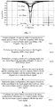
- FIG. 2 is a schematic flowchart of a beam signal tracking method according to an embodiment of the present invention. As shown in FIG. 2 , the beam signal tracking method provided in this embodiment includes the following steps.
- S10 Obtain a Doppler frequency shift of a receive-beam signal, and determine a Doppler frequency shift change speed of the receive-beam signal according to the Doppler frequency shift.
- S20 Determine a scanning speed and a scanning angle step size of the receive-beam signal according to the Doppler frequency shift change speed.
- S30 Scan a receive beam according to the scanning speed and the scanning angle step size, and determine a beam angle that is formed when the receive-beam signal is aligned with a transmit-beam signal.
- S40 Determine phase configuration information of a phase shifter according to the beam angle that is formed when the receive-beam signal is aligned with the transmit-beam signal.
- S50 Configure the phase shifter according to the phase configuration information of the phase shifter, so that the receive-beam signal is aligned with the transmit-beam signal.
- the beam signal tracking processing procedure may be executed by a transmit end or a receive end in a wireless communications system, or may be executed cooperatively by the transmit end and the receive end.
- the beam signal tracking processing procedure may be executed by using a baseband processor of the transmit end and/or the receive end or may be executed by using a beam signal tracking apparatus.
- An objective of beam signal tracking is to find a beam angle that is formed when a receive beam is aligned with a transmit beam, that is, to perform beam alignment, so as to achieve better quality of beam forming transmission.
- the quality of beam forming transmission may be estimated according to a power of a receive-beam signal.
- a beam angle corresponding to a maximum power of the receive-beam signal is the beam angle that is formed when the beams are aligned.
- phase configuration is performed on the phase shifter by using phase configuration information, which exists when the beams are aligned, of the phase shifter, so that the receive beam is aligned with the transmit beam, so as to improve the quality of beam forming transmission.
- phase configuration of the phase shifter needs to be continuously adjusted by means of a beam tracking process, so as to change the quality of beam forming transmission.
- beam scanning is performed with a scanning speed of n (times/s) and a scanning angle step size of a (degrees).
- phase configuration of the phase shifter is performed at intervals of 1/n seconds, to configure the phase shifter in sequence so that a beam angle changes as follows: -90, -90+a, -90+2a, -90+3a, «, - 90+ma, 90.
- Received signal powers corresponding to different beam angles are simultaneously detected, to obtain m+2 power values.
- a maximum received signal power is found in the m+2 power values, and a beam angle corresponding to the maximum received signal power, that is, a beam angle that is formed when the beams are aligned, is found accordingly.
- phase configuration is performed on the phase shifter by using phase configuration information, which exists when the beams are aligned, of the phase shifter, so that the receive beam is aligned with the transmit beam, to complete one beam tracking process. For example, it is assumed that beam tracking is performed by using three degrees as a scanning angle step size. In one beam tracking process, beam scanning needs to be performed for 61 times.
- Scanning angles are sequentially -90, -87, -84, -81, «, 87, 90, that is, phase configuration of the phase shifter is performed for 61 times, so that the beam angles are sequentially -90, -87, -84, -81, «, 87, 90. If a scanning speed is 50 times per second, it takes about 1.22 seconds to complete one beam tracking process. If a scanning speed is 100 times per second, it takes about 0.61 second to complete one beam tracking process. Correspondingly, 61 power values can be obtained for different beam angles.
- phase configuration is performed on the phase shifter by using phase configuration information of the phase shifter corresponding to the beam angle of 45 degrees, so that the receive beam is aligned with the transmit beam. It can be understood that in order to obtain relatively good beam tracking quality, mainly, an appropriate scanning speed and scanning angle step size need to be selected in a beam tracking process.
- FIG. 3 is a schematic diagram of beam tracking in a mobile communications system.
- beam pointing of the mobile station M and a signal tower B is constantly maintained in a tracked state.
- a corresponding beam angle ⁇ continuously changes with the movement of the mobile station M, so that a beam of the signal tower is aligned with a beam of the mobile station, ensuring transmission quality of beam forming, so as to ensure continuity of a communications service.
- FIG. 4 is a schematic diagram of an emulation of a correspondence between a projection distance from a mobile station to a signal tower and a beam angle; FIG.
- FIG. 5 is a schematic diagram of an emulation of a correspondence between a projection distance from a mobile station to a signal tower and a change gradient of a beam angle corresponding to FIG. 4 .
- parameters ⁇ , h, and D in FIG. 4 and FIG. 5 refer to annotations shown in FIG. 3 , where ⁇ is a beam angle in FIG. 3 , h is a vertical distance between the mobile station and the signal tower in FIG. 3 , and D is a projection value, in a movement direction of the mobile station, of a distance / between the mobile station and the signal tower in FIG. 3 . It can be seen with reference to FIG. 3 to FIG. 5 that when the mobile station moves close to or away from the signal tower, the beam angle changes.
- the beam angle changes relatively slowly, and a gradient of the beam angle is relatively small.
- the beam angle changes drastically, and the gradient of the beam angle is relatively great.
- the phase and frequency may change.
- a change is usually referred to as the Doppler effect.
- a difference, caused by the Doppler effect, between a frequency of a received signal and a frequency of a transmitted signal is referred to as a Doppler frequency shift.
- the Doppler effect affects quality of communication. How to eliminate or reduce impact of the Doppler effect on wireless communication is a problem that needs to be resolved to perform wireless communication during high-speed movement, and a commonly used method is: estimating a Doppler frequency shift, and compensating for a frequency offset of a received signal according to an estimation result.
- FIG. 6 is an emulation schematic diagram of a correspondence between ⁇ and a Doppler frequency shift
- FIG. 7 is a schematic diagram of a correspondence between ⁇ and a change gradient of a Doppler frequency shift corresponding to FIG. 6 .
- ⁇ and h in FIG. 6 and FIG. 7 refer to annotations shown in FIG. 3 , where ⁇ is an angle between the movement direction of the mobile station and the receive beam in FIG. 3 , h is a distance between the mobile station and the signal tower, and f d is a Doppler frequency shift of a received signal. It can be seen with reference to FIG. 3 , FIG. 6 , and FIG.
- the Doppler frequency shift changes.
- the Doppler frequency shift changes slowly, and a gradient of the Doppler frequency shift is relatively small.
- the Doppler frequency shift changes drastically, and the gradient of the Doppler frequency shift is relatively great.
- the scanning speed and the scanning angle step size that are used for beam tracking can be determined according to the Doppler frequency shift change speed of the system.
- the Doppler frequency shift change speed may be obtained by calculating a gradient value of the Doppler frequency shift.
- the Doppler frequency shift change speed is obtained by calculating a derivative value of the Doppler frequency shift.
- the gradient value and the derivative value of the Doppler frequency shift may be separately calculated, and then the Doppler frequency shift change speed is obtained according to an average value of the gradient value and the derivative value of the Doppler frequency shift.
- a table of correspondences between the Doppler frequency shift change speed and the scanning speed and between the Doppler frequency shift change speed and the scanning angle step size may be prestored in the beam signal tracking apparatus.
- the corresponding scanning speed and scanning angle step size may be obtained by directly looking up the table according to the Doppler frequency shift change speed, and this can simplify a data processing procedure and reduce load of a data processing unit. It can be understood that the table of correspondence between the Doppler frequency shift change speed and the scanning speed and between the Doppler frequency shift change speed and the scanning angle step size may be obtained by means of experiments and the like.
- the scanning speed and the scanning angle step size are determined according to the Doppler frequency shift change speed.
- the scanning speed and the scanning angle step size that are used for beam tracking may be obtained by looking up the table according to the gradient value of the Doppler frequency shift.
- the scanning speed and the scanning angle step size that are used for beam tracking may be obtained by looking up the table according to the derivative value of the Doppler frequency shift.
- a scanning speed n 1 and a scanning angle step size a 1 that are used for beam tracking may also first be obtained by looking up the table according to the gradient value of the Doppler frequency shift; at the same time, a scanning speed n 2 and a scanning angle step size a 2 that are used for beam tracking may be obtained by looking up the table according to the derivative value of the Doppler frequency shift; then a scanning speed used for beam tracking is obtained according to an average value of n 1 and n 2 , and a scanning angle step size used for beam tracking may be obtained according to an average value of a 1 and a 2 .
- a scanning speed and a scanning angle step size during a beam tracking process are adaptively adjusted by using a Doppler frequency shift change speed of a system. While beam tracking quality is ensured, maximum data transmission efficiency is achieved, and communication efficiency is improved.
- the scanning speed and the scanning angle step size during the beam tracking process are adaptively adjusted, and data transmission efficiency is improved.
- FIG. 8 is a schematic flowchart of another beam signal tracking method according to an embodiment of the present invention. As shown in FIG. 8 , in this embodiment, based on the embodiment shown in FIG. 2 , further, S20 may specifically include the following steps.
- S202 Determine a scanning speed and a scanning angle step size according to the normalized Doppler frequency shift change speed.
- normalization processing is to map to-be-processed data into a required range, for example, between 0 and 1, after normalization processing.
- a common normalization processing method may be used.
- a deviation standardization (Min-Max Normalization) method linear transformation may be performed on data, so as to map a result value to [0-1].
- Z-score Normalization standard deviation standardization
- data standardization may be performed according to a mean value and a standard deviation of data, and the processed data satisfies standard normal distribution, that is, the mean value is 0, and the standard deviation is 1.
- the Doppler frequency shift change speed may be mapped to a relatively small particular interval by means of normalization processing, so that the correspondence between the Doppler frequency shift change speed and the scanning speed and the correspondence between the Doppler frequency shift change speed and the scanning angle step size are more obvious, to facilitate determining of the scanning speed and the scanning angle step size.
- the beam signal tracking apparatus may first determine a change trend of the Doppler frequency shift change speed according to the normalized Doppler frequency shift change speed, and then correspondingly adjust the scanning speed and the scanning angle step size according to the change trend of the Doppler frequency shift change speed.
- the scanning speed and the scanning angle step size may be correspondingly increased if it is determined that the normalized Doppler frequency shift change speed increases; the scanning speed and the scanning angle step size may be correspondingly reduced if it is determined that the normalized Doppler frequency shift change speed decreases; and the scanning speed and the scanning angle step size are maintained if it is determined that the normalized Doppler frequency shift change speed remains unchanged.
- the beam signal tracking apparatus may preset initial values of the scanning speed and the scanning angle step size that are used for beam tracking and then adjust the initial values of the scanning speed and the scanning angle step size according to the change trend of the normalized Doppler frequency shift change speed.
- the table of the correspondences between the normalized Doppler frequency shift change speed and the scanning speed and between the normalized Doppler frequency shift change speed and the scanning angle step size may be prestored in the beam signal tracking apparatus, and the scanning speed and the scanning angle step size may be obtained by directly looking up the table according to the normalized Doppler frequency shift change speed.
- normalization processing can simplify calculation, in this embodiment, preferably, normalization processing is performed on the Doppler frequency shift change speed, and then the scanning speed and the scanning angle step size are determined according to the normalized Doppler frequency shift change speed, so that the scanning speed and the scanning angle step size are determined more conveniently and quickly and a data processing procedure is simplified.
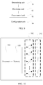
- FIG. 9 is a schematic diagram of a beam signal tracking apparatus according to an embodiment of the present invention.
- the apparatus may be a control circuit configured to control phase configuration of a phase shifter in a phase antenna array system.
- the control circuit is connected to the phase shifter, and then the phase shifter is coupled to each antenna in the antenna array.
- a phase of the phase shifter is controlled so that beam pointing of Tx and Rx is constantly maintained in a tracked state.
- the beam signal tracking apparatus provided in this embodiment may execute steps of the beam signal tracking methods provided in the embodiments shown in FIG. 2 and FIG. 8 of the present invention. Details are not provided herein again.
- the beam signal tracking apparatus includes a determining unit 91, a processing unit 92, a phase control unit 93, and a configuration unit 94.
- the determining unit 91 is configured to: obtain a Doppler frequency shift of a receive-beam signal, and determine a Doppler frequency shift change speed of the receive-beam signal according to the Doppler frequency shift.
- the processing unit 92 is configured to determine a scanning speed and a scanning angle step size of the receive-beam signal according to the Doppler frequency shift change speed.
- the determining unit 91 may be specifically configured to calculate a gradient value of the Doppler frequency shift to obtain the Doppler frequency shift change speed, or may be configured to calculate a derivative value of the Doppler frequency shift to obtain the Doppler frequency shift change speed. In an example of an implementation manner, in an actual application, the determining unit 91 may be specifically configured to: calculate a gradient value and a derivative value of the Doppler frequency shift; and then calculate an average value of the gradient value and the derivative value of the Doppler frequency shift to obtain the Doppler frequency shift change speed.
- the phase control unit 93 is configured to perform beam tracking according to the scanning speed and the scanning angle step size. Specifically, in an actual application, the phase control unit 93 is specifically configured to: scan the receive-beam signal according to the scanning speed and the scanning angle step size that are determined by the processing unit 92, and determine a beam angle that is formed when the receive-beam signal is aligned with a transmit-beam signal, where the beam angle that is formed when the receive-beam signal is aligned with the transmit-beam signal is a beam angle corresponding to a maximum power of the receive-beam signal.
- the configuration unit 94 is configured to: determine phase configuration information of a phase shifter according to the beam angle that is formed when the receive-beam signal is aligned with the transmit-beam signal, and then configure the phase shifter according to the phase configuration information of the phase shifter, so that the receive-beam signal is aligned with the transmit-beam signal.
- the processing unit 92 may be specifically configured to query a table of correspondences between the Doppler frequency shift change speed and the scanning speed and between the Doppler frequency shift change speed and the scanning angle step size according to the Doppler frequency shift change speed, to determine the scanning speed and the scanning angle step size.
- the processing unit 92 may further be specifically configured to: perform normalization processing on the Doppler frequency shift change speed, and determine the scanning speed and the scanning angle step size according to the normalized Doppler frequency shift change speed.
- the processing unit 92 may specifically include an adjustment module.
- the adjustment module may be configured to adjust the scanning speed and the scanning angle step size according to a change trend of the normalized Doppler frequency shift change speed.
- the adjustment module may be specifically configured to: increase the scanning speed and the scanning angle step size when the normalized Doppler frequency shift change speed increases; reduce the scanning speed and the scanning angle step size when the normalized Doppler frequency shift change speed decreases; and maintain the scanning speed and the scanning angle step size when the normalized Doppler frequency shift change speed remains unchanged.
- the beam signal tracking apparatus may be disposed at a transmit end or may be disposed at a receive end.
- a transmit device and a receive device may also be included in a single component and may share an antenna and/or a phase shifter or may share the beam signal tracking apparatus.
- the beam signal tracking apparatus provided in this embodiment is configured to: during a beam tracking process, adaptively adjust a scanning speed and a scanning angle step size in the beam tracking process. While beam tracking quality is ensured, maximum data transmission efficiency is achieved, and communication efficiency is improved.
- the beam signal tracking apparatus provided in this embodiment is configured to execute the beam signal tracking methods provided in the embodiments shown in FIG. 2 and FIG. 8 . Implementation principles and technical effects thereof are similar and are not described in detail herein again.
- FIG. 10 is a schematic diagram of a communications device according to an embodiment of the present invention.
- the communications device may be specifically a base station (Base Station, BS for short) in a communications system or may be a mobile station (Mobile Station, MS for short), that is, user equipment.
- the communications device may implement steps of the beam signal tracking methods provided in the embodiments shown in FIG. 2 and FIG. 8 of the present invention, details are not described herein again.
- the communications device includes a transceiver antenna array 101, a phase shifter 102, a memory 103, and a processor 104 coupled with the memory 103.
- the phase shifter 102 is coupled to each antenna unit in the transceiver antenna array 101.
- the processor 104 may be configured to: obtain a Doppler frequency shift of a receive-beam signal, and determine a Doppler frequency shift change speed of the receive-beam signal according to the Doppler frequency shift; determine a scanning speed and a scanning angle step size of the receive-beam signal according to the Doppler frequency shift change speed; scan the receive-beam signal according to the scanning speed and the scanning angle step size, and determine a beam angle that is formed when the receive-beam signal is aligned with a transmit-beam signal, where the beam angle that is formed when the receive-beam signal is aligned with the transmit-beam signal is a beam angle corresponding a maximum power of the receive-beam signal; determine phase configuration information of a phase shifter according to the beam angle that is formed when the receive-beam signal is aligned with the transmit-beam signal; and configure the phase shifter according to the phase configuration information of the phase shifter, so that the receive-beam signal is aligned with the transmit-beam signal.
- processor 104 may specifically perform normalization processing on the Doppler frequency shift change speed, and determine the scanning speed and the scanning angle step size according to the normalized Doppler frequency shift change speed.
- the scanning speed and the scanning angle step size are increased when the normalized Doppler frequency shift change speed increases; the scanning speed and the scanning angle step size are reduced when the normalized Doppler frequency shift change speed decreases; and the scanning speed and the scanning angle step size are maintained when the normalized Doppler frequency shift change speed remains unchanged.
- the processor 104 may specifically calculate a gradient value of the Doppler frequency shift to obtain the Doppler frequency shift change speed, or calculate a derivative value of the Doppler frequency shift to obtain the Doppler frequency shift change speed.
- the processor 104 may also calculate a gradient value and a derivative value of the Doppler frequency shift, and then calculate an average value of the gradient value and the derivative value of the Doppler frequency shift to obtain the Doppler frequency shift change speed.
- the communications device provided in this embodiment may implement the beam signal tracking methods provided in the embodiments shown in FIG. 2 and FIG. 8 . Implementation principles and technical effects thereof are similar and are not described in detail herein again.
- An embodiment of the present invention further provides a phase control microwave communications system, including a base station and user equipment, where at least one of the base station and the user equipment includes the beam signal tracking apparatus provided in the embodiment shown in FIG. 9 .
- An embodiment of the present invention further provides a phase control microwave communications system, including the communications device provided in the embodiment shown in FIG.10 .
- the program may be stored in a computer-readable storage medium.
- the foregoing storage medium includes: any medium that can store program code, such as a ROM, a RAM, a magnetic disk, or an optical disc.
Landscapes
- Engineering & Computer Science (AREA)
- Radar, Positioning & Navigation (AREA)
- Remote Sensing (AREA)
- Computer Networks & Wireless Communication (AREA)
- Physics & Mathematics (AREA)
- General Physics & Mathematics (AREA)
- Mobile Radio Communication Systems (AREA)
- Radio Transmission System (AREA)
- Variable-Direction Aerials And Aerial Arrays (AREA)
Claims (6)
- Procédé de suivi de signal de faisceau entre une extrémité de transmission et une extrémité de réception, réalisé par l'extrémité de réception, le procédé comprenant :• l'obtention d'un décalage de fréquence Doppler d'un signal de faisceau de réception, et la détermination d'une vitesse de changement de décalage de fréquence Doppler du signal de faisceau de réception selon le décalage de fréquence Doppler (S10),• la détermination d'une vitesse de balayage et d'une taille de pas d'angle de balayage d'un faisceau de réception du signal de faisceau de réception selon la vitesse de changement de décalage de fréquence Doppler (S20) ;• le balayage du faisceau de réception du signal de faisceau de réception selon la vitesse de balayage et la taille de pas d'angle de balayage, et la détermination d'un angle de faisceau qui est formé lorsque le faisceau de réception du signal de faisceau de réception est aligné avec un faisceau de transmission d'un signal de faisceau de transmission de l'extrémité de transmission, dans lequel l'angle de faisceau qui est formé lorsque le faisceau de réception est aligné avec le faisceau de transmission est un angle de faisceau correspondant à une puissance maximum du signal de faisceau de réception (S30) ;• la détermination d'informations de configuration de phase d'un déphaseur selon l'angle de faisceau qui est formé lorsque le faisceau de réception est aligné avec le faisceau de transmission (S40) ; et• la configuration du déphaseur selon les informations de configuration de phase du déphaseur, pour que le faisceau de réception soit aligné avec le faisceau de transmission (S50).
- Procédé selon la revendication 1, dans lequel la détermination de la vitesse de balayage et de la taille de pas d'angle de balayage du faisceau de réception selon la vitesse de changement de décalage de fréquence Doppler comprend :la réalisation d'un traitement de normalisation sur la vitesse de changement de décalage de fréquence Doppler ; etla détermination de la vitesse de balayage et de la taille de pas d'angle de balayage selon la vitesse normalisée de changement de décalage de fréquence Doppler.
- Procédé selon la revendication 2, dans lequel la détermination de la vitesse de balayage et de la taille de pas d'angle de balayage selon la vitesse normalisée de changement de décalage de fréquence Doppler comprend :l'augmentation de la vitesse de balayage et de la taille de pas d'angle de balayage lorsque la vitesse normalisée de changement de décalage de fréquence Doppler augmente ;la diminution de la vitesse de balayage et de la taille de pas d'angle de balayage lorsque la vitesse normalisée de changement de décalage de fréquence Doppler diminue ; etle maintien de la vitesse de balayage et de la taille de pas d'angle de balayage lorsque la vitesse normalisée de changement de décalage de fréquence Doppler reste inchangée.
- Procédé selon la revendication 1, dans lequel la détermination de la vitesse de changement de décalage de fréquence Doppler du signal de faisceau de réception comprend spécifiquement :le calcul d'une valeur de gradient du décalage de fréquence Doppler du signal de faisceau de réception pour obtenir la vitesse de changement de décalage de fréquence Doppler ; oule calcul d'une valeur de dérivée du décalage de fréquence Doppler du signal de faisceau de réception pour obtenir la vitesse de changement de décalage de fréquence Doppler.
- Procédé selon la revendication 1, dans lequel la détermination de la vitesse de changement de décalage de fréquence Doppler du signal de faisceau de réception comprend spécifiquement :le calcul d'une valeur de gradient et d'une valeur de dérivée du décalage de fréquence Doppler du signal de faisceau de réception ; etle calcul d'une valeur moyenne de la valeur de gradient et de la valeur de dérivée du décalage de fréquence Doppler du signal de faisceau de réception pour obtenir la vitesse de changement de décalage de fréquence Doppler.
- Extrémité de réception, configurée et prévue pour réaliser l'un quelconque des procédés selon les revendications 1 à 5.
Applications Claiming Priority (1)
| Application Number | Priority Date | Filing Date | Title |
|---|---|---|---|
| PCT/CN2015/079765 WO2016187797A1 (fr) | 2015-05-26 | 2015-05-26 | Procédé, dispositif et système de suivi d'un signal de faisceau |
Publications (3)
| Publication Number | Publication Date |
|---|---|
| EP3279687A1 EP3279687A1 (fr) | 2018-02-07 |
| EP3279687A4 EP3279687A4 (fr) | 2018-04-25 |
| EP3279687B1 true EP3279687B1 (fr) | 2019-07-10 |
Family
ID=57392511
Family Applications (1)
| Application Number | Title | Priority Date | Filing Date |
|---|---|---|---|
| EP15892878.8A Active EP3279687B1 (fr) | 2015-05-26 | 2015-05-26 | Procédé, dispositif et système de suivi d'un signal de faisceau |
Country Status (4)
| Country | Link |
|---|---|
| US (1) | US10622713B2 (fr) |
| EP (1) | EP3279687B1 (fr) |
| CN (1) | CN107615091B (fr) |
| WO (1) | WO2016187797A1 (fr) |
Families Citing this family (29)
| Publication number | Priority date | Publication date | Assignee | Title |
|---|---|---|---|---|
| US10505643B2 (en) * | 2015-03-26 | 2019-12-10 | Lg Electronics Inc. | Method and device for estimating doppler frequency by using beam scanning process in wireless communication system |
| US10470109B2 (en) * | 2017-03-24 | 2019-11-05 | Qualcomm Incorporated | Methods for adapting beam scanning frequencies in millimeter wave systems |
| CN109788576B (zh) | 2017-11-15 | 2020-10-23 | 华为技术有限公司 | 随机接入方法、装置及设备 |
| US10411765B2 (en) * | 2017-12-22 | 2019-09-10 | Motorola Mobility Llc | Body detection using near field millimeter wave scattering |
| KR102486812B1 (ko) | 2018-04-12 | 2023-01-11 | 삼성전자주식회사 | 전자 장치 및 전자 장치에서 대역폭 적응 기반 전력 제어 방법 |
| KR20200022266A (ko) | 2018-08-22 | 2020-03-03 | 삼성전자주식회사 | 복수의 안테나들에 입력되는 신호의 위상을 조정하는 방법 및 이를 구현한 전자 장치 |
| CN109633717A (zh) * | 2018-11-06 | 2019-04-16 | 阳光凯讯(北京)科技有限公司 | 一种应用于低轨卫星定位系统的多普勒频移定位方法 |
| CN110278014B (zh) * | 2019-03-28 | 2021-06-01 | 华为技术有限公司 | 波束调整方法、装置及设备 |
| EP4000185A1 (fr) * | 2019-07-15 | 2022-05-25 | Telefonaktiebolaget LM Ericsson (publ) | Noeud de réseau radio et procédés en son sein permettant de transmettre une mise à jour d'indication de configuration de transmission (tci) à un dispositif sans fil |
| US12504496B2 (en) | 2019-11-27 | 2025-12-23 | Rockwell Collins, Inc. | Station keeping using doppler null scanning |
| US12531596B2 (en) | 2019-11-27 | 2026-01-20 | Rockwell Collins, Inc. | Doppler-nulling for directional networks (spatial awareness) |
| US12137048B2 (en) | 2019-11-27 | 2024-11-05 | Rockwell Collins, Inc. | System and method for spatial awareness network routing |
| US12571868B2 (en) | 2019-11-27 | 2026-03-10 | Rockwell Collins, Inc. | Doppler null scanning for coordination including expendable platforms (spatial awareness) |
| US12553978B2 (en) | 2019-11-27 | 2026-02-17 | Rockwell Collins, Inc. | Proactive link acquisition (spatial awareness) |
| US12618929B2 (en) | 2019-11-27 | 2026-05-05 | Rockwell Collins, Inc. | Navigational beaconing via doppler null scanning (DNS) |
| US12584986B2 (en) | 2019-11-27 | 2026-03-24 | Rockwell Collins, Inc. | Reliable efficient flooding with Doppler nulling (spatial awareness) |
| US12540997B2 (en) | 2019-11-27 | 2026-02-03 | Rockwell Collins, Inc. | System and method for application of doppler null scanning (DNS) to position navigation timing (PNT) |
| US12498442B2 (en) | 2019-11-27 | 2025-12-16 | Rockwell Collins, Inc. | Robust addressing schema for spatial awareness via doppler null scanning (DNS) |
| US12050279B2 (en) | 2019-11-27 | 2024-07-30 | Rockwell Collins, Inc. | Doppler nulling spatial awareness (DNSA) solutions for non-terrestrial networks |
| US12474431B2 (en) | 2019-11-27 | 2025-11-18 | Rockwell Collins, Inc. | Doppler-nulling and two-way timing and ranging (spatial awareness) |
| US12523733B2 (en) | 2019-11-27 | 2026-01-13 | Rockwell Collins, Inc | Directional enhancements for mobile ad hoc networks (MANET) via doppler null scanning (DNS) |
| US12546845B2 (en) | 2021-11-23 | 2026-02-10 | Rockwell Collins, Inc. | Search and rescue system with doppler-nulling spatial awareness |
| US11977173B2 (en) | 2019-11-27 | 2024-05-07 | Rockwell Collins, Inc. | Spoofing and denial of service detection and protection with doppler nulling (spatial awareness) |
| US12326506B2 (en) | 2019-11-27 | 2025-06-10 | Rockwell Collins, Inc. | DNS spatial discoveries with on-going traffic |
| US12111406B2 (en) | 2019-11-27 | 2024-10-08 | Rockwell Collins, Inc. | Adaptive doppler-nulling digitization for high-resolution |
| US12153150B2 (en) | 2019-11-27 | 2024-11-26 | Rockwell Collins, Inc. | Doppler nulling scanning (DNS) security (spatial awareness) |
| CN113009526A (zh) * | 2021-02-23 | 2021-06-22 | 重庆两江卫星移动通信有限公司 | 一种低轨卫星的地面跟踪装置和方法 |
| EP4515722A1 (fr) * | 2022-04-29 | 2025-03-05 | Telefonaktiebolaget LM Ericsson (publ) | Formation de faisceau de récepteur |
| CN114924263B (zh) * | 2022-07-22 | 2022-10-18 | 南京隼眼电子科技有限公司 | 运动目标的速度解模糊方法、装置及存储介质 |
Family Cites Families (25)
| Publication number | Priority date | Publication date | Assignee | Title |
|---|---|---|---|---|
| US4041496A (en) * | 1976-04-26 | 1977-08-09 | Norris Paul R | Automatic direction finding system |
| US4520493A (en) * | 1981-12-07 | 1985-05-28 | Hughes Aircraft Company | Adaptive recursive frequency offset tracking system |
| US6229475B1 (en) * | 1987-04-27 | 2001-05-08 | Raytheon Company | Pulse doppler radar system with improved cluster target resolution capability |
| US5691974A (en) | 1995-01-04 | 1997-11-25 | Qualcomm Incorporated | Method and apparatus for using full spectrum transmitted power in a spread spectrum communication system for tracking individual recipient phase, time and energy |
| US6236363B1 (en) * | 1998-01-30 | 2001-05-22 | Micronetics Wireless | Smart antenna channel simulator and test system |
| CN1301970A (zh) * | 1999-12-30 | 2001-07-04 | 中国科学院空间科学与应用研究中心 | 实时变参数滤波笔形波束扫描雷达散射计及其设计方法 |
| CN100365429C (zh) * | 2004-11-05 | 2008-01-30 | 清华大学 | 一种合成孔径雷达运动目标成像方法 |
| JP4496954B2 (ja) * | 2004-12-24 | 2010-07-07 | 日本電気株式会社 | 干渉型レーダー |
| US7710319B2 (en) * | 2006-02-14 | 2010-05-04 | Sibeam, Inc. | Adaptive beam-steering methods to maximize wireless link budget and reduce delay-spread using multiple transmit and receive antennas |
| TWI340251B (en) | 2007-10-09 | 2011-04-11 | Univ Nat Taiwan | Method and system for radar tracking of moving target from moving station |
| CN101207235B (zh) | 2007-12-18 | 2011-10-05 | 中国电子科技集团公司第五十四研究所 | 移动卫星通信相控阵天线 |
| EP2244102A1 (fr) | 2009-04-21 | 2010-10-27 | Astrium Limited | Système radar |
| CN101561970B (zh) * | 2009-05-25 | 2011-06-08 | 中国人民解放军理工大学气象学院 | 一种微波车辆检测雷达的控制方法 |
| CN102076087B (zh) | 2009-11-19 | 2014-01-01 | 中兴通讯股份有限公司 | 寻呼方法及基站控制器 |
| CN101936756B (zh) * | 2010-08-31 | 2012-12-19 | 华南理工大学 | 一种多频相控阵超声多普勒流量检测系统及方法 |
| DE102010044742A1 (de) * | 2010-09-08 | 2012-03-08 | Atlas Elektronik Gmbh | Verfahren und Vorrichrung zur Bestimmung einer aus dem Doppler-Effekt resultierenden Doppler-Frequenzverschiebung |
| CN102176010B (zh) * | 2011-01-21 | 2013-01-23 | 西安电子科技大学 | 基于多发单收的无源雷达定位跟踪系统及定位跟踪方法 |
| CN102292870B (zh) * | 2011-06-16 | 2013-09-11 | 华为技术有限公司 | 相控阵天线对准方法和装置以及相控阵天线 |
| WO2013006194A1 (fr) | 2011-07-01 | 2013-01-10 | Intel Corporation | Livre de codes structuré pour réseau circulaire uniforme (uca) |
| EP2951605B1 (fr) * | 2013-02-01 | 2019-01-09 | Telefonaktiebolaget LM Ericsson (publ) | Procédé pour un alignement d'antennes multifaisceaux dans un scénario de non-visibilité directe |
| EP3493614B1 (fr) | 2013-02-27 | 2022-04-27 | Huawei Technologies Co., Ltd. | Procédés, dispositifs, produits de programmes informatique et système d'optimisation de radiomessagerie |
| EP2996405A4 (fr) | 2013-05-10 | 2016-11-16 | Fujitsu Ltd | Procédé et dispositif de calcul d'opportunité de radiomessagerie pendant un cycle de radiomessagerie étendu |
| CN103323847B (zh) * | 2013-05-30 | 2015-08-19 | 中国科学院电子学研究所 | 一种动目标点迹仿真及轨迹关联方法和装置 |
| CN104122548B (zh) * | 2014-07-30 | 2016-08-24 | 西安电子科技大学 | 机扫米波阵列雷达测角方法 |
| CN104297747B (zh) | 2014-09-23 | 2017-07-14 | 上海无线电设备研究所 | 相控阵波束跟踪方法 |
-
2015
- 2015-05-26 WO PCT/CN2015/079765 patent/WO2016187797A1/fr not_active Ceased
- 2015-05-26 CN CN201580019785.XA patent/CN107615091B/zh active Active
- 2015-05-26 EP EP15892878.8A patent/EP3279687B1/fr active Active
-
2017
- 2017-11-22 US US15/821,404 patent/US10622713B2/en active Active
Non-Patent Citations (1)
| Title |
|---|
| None * |
Also Published As
| Publication number | Publication date |
|---|---|
| EP3279687A1 (fr) | 2018-02-07 |
| EP3279687A4 (fr) | 2018-04-25 |
| CN107615091A (zh) | 2018-01-19 |
| CN107615091B (zh) | 2020-04-14 |
| US10622713B2 (en) | 2020-04-14 |
| US20180076520A1 (en) | 2018-03-15 |
| WO2016187797A1 (fr) | 2016-12-01 |
Similar Documents
| Publication | Publication Date | Title |
|---|---|---|
| US10622713B2 (en) | Beam signal tracking method, device and system | |
| Samimi et al. | 28 GHz millimeter-wave ultrawideband small-scale fading models in wireless channels | |
| US11962097B2 (en) | Method and apparatus for selecting antenna elements of an antenna array | |
| US20200187126A1 (en) | Method for performing radar-assisted wireless data communication | |
| Barneto et al. | Radio-based sensing and indoor mapping with millimeter-wave 5G NR signals | |
| El-Sayed et al. | Evaluation of localization methods in millimeter-wave wireless systems | |
| Ruble et al. | Wireless localization for mmWave networks in urban environments | |
| Anjinappa et al. | Millimeter-wave V2X channels: Propagation statistics, beamforming, and blockage | |
| Priebe et al. | AoA, AoD and ToA characteristics of scattered multipath clusters for THz indoor channel modeling | |
| US11533095B2 (en) | Data-driven beam tracking method and device for mobile millimeter wave communication system and storage medium | |
| EP4557780A1 (fr) | Procédé de positionnement et de détection pour terminal, dispositif électronique et support de stockage | |
| Qu et al. | Near-field integrated sensing and communications: Unlocking potentials and shaping the future | |
| Fu et al. | Multi-IRS enhanced wireless coverage: Deployment optimization based on large-scale channel knowledge | |
| Deutschmann et al. | XL-MIMO channel modeling and prediction for wireless power transfer | |
| Kelner et al. | Evaluation of angle spread and power balance for design of radio links with directional antennas in multipath environment | |
| Yang et al. | Channel measurements at 140 and 220 GHz in an outdoor street canyon environment | |
| WO2025010632A1 (fr) | Rapport de capacité de réseau d'antennes virtuelles | |
| Wang et al. | Quasi-deterministic model for doppler spread in millimeter-wave communication systems | |
| US20240380534A1 (en) | Base station, wireless communication method, and wireless communication system | |
| Aghdam et al. | Statistical Characterization of SNR in RIS-Aided Wireless Communication Systems | |
| Nayir et al. | Experimental Assessment of Misalignment Effects in Terahertz Communications | |
| Peng et al. | Effects of phase shift errors on the antenna directivity of phased arrays in indoor terahertz communications | |
| Gao et al. | Pseudolite Self-Interference Cancellation without GNSS Signal Distortion | |
| Kim et al. | Development of link context-aware millimeterwave beam switching system using depth-sensor | |
| Liu et al. | A Comprehensive Survey of 3GPP Release 19 ISAC Channel Modeling: From Empirical Features to Unified Methodology and Standardized Simulator |
Legal Events
| Date | Code | Title | Description |
|---|---|---|---|
| STAA | Information on the status of an ep patent application or granted ep patent |
Free format text: STATUS: THE INTERNATIONAL PUBLICATION HAS BEEN MADE |
|
| PUAI | Public reference made under article 153(3) epc to a published international application that has entered the european phase |
Free format text: ORIGINAL CODE: 0009012 |
|
| STAA | Information on the status of an ep patent application or granted ep patent |
Free format text: STATUS: REQUEST FOR EXAMINATION WAS MADE |
|
| 17P | Request for examination filed |
Effective date: 20171103 |
|
| AK | Designated contracting states |
Kind code of ref document: A1 Designated state(s): AL AT BE BG CH CY CZ DE DK EE ES FI FR GB GR HR HU IE IS IT LI LT LU LV MC MK MT NL NO PL PT RO RS SE SI SK SM TR |
|
| AX | Request for extension of the european patent |
Extension state: BA ME |
|
| A4 | Supplementary search report drawn up and despatched |
Effective date: 20180323 |
|
| RIC1 | Information provided on ipc code assigned before grant |
Ipc: H01Q 3/36 20060101ALI20180319BHEP Ipc: G01S 13/74 20060101ALI20180319BHEP Ipc: G01S 13/66 20060101ALI20180319BHEP Ipc: G01S 13/72 20060101AFI20180319BHEP |
|
| DAV | Request for validation of the european patent (deleted) | ||
| DAX | Request for extension of the european patent (deleted) | ||
| GRAP | Despatch of communication of intention to grant a patent |
Free format text: ORIGINAL CODE: EPIDOSNIGR1 |
|
| STAA | Information on the status of an ep patent application or granted ep patent |
Free format text: STATUS: GRANT OF PATENT IS INTENDED |
|
| INTG | Intention to grant announced |
Effective date: 20181218 |
|
| GRAS | Grant fee paid |
Free format text: ORIGINAL CODE: EPIDOSNIGR3 |
|
| GRAA | (expected) grant |
Free format text: ORIGINAL CODE: 0009210 |
|
| STAA | Information on the status of an ep patent application or granted ep patent |
Free format text: STATUS: THE PATENT HAS BEEN GRANTED |
|
| AK | Designated contracting states |
Kind code of ref document: B1 Designated state(s): AL AT BE BG CH CY CZ DE DK EE ES FI FR GB GR HR HU IE IS IT LI LT LU LV MC MK MT NL NO PL PT RO RS SE SI SK SM TR |
|
| REG | Reference to a national code |
Ref country code: GB Ref legal event code: FG4D |
|
| REG | Reference to a national code |
Ref country code: CH Ref legal event code: EP Ref country code: AT Ref legal event code: REF Ref document number: 1154165 Country of ref document: AT Kind code of ref document: T Effective date: 20190715 |
|
| REG | Reference to a national code |
Ref country code: DE Ref legal event code: R096 Ref document number: 602015033773 Country of ref document: DE |
|
| REG | Reference to a national code |
Ref country code: IE Ref legal event code: FG4D |
|
| REG | Reference to a national code |
Ref country code: NL Ref legal event code: MP Effective date: 20190710 |
|
| REG | Reference to a national code |
Ref country code: LT Ref legal event code: MG4D |
|
| REG | Reference to a national code |
Ref country code: AT Ref legal event code: MK05 Ref document number: 1154165 Country of ref document: AT Kind code of ref document: T Effective date: 20190710 |
|
| PG25 | Lapsed in a contracting state [announced via postgrant information from national office to epo] |
Ref country code: NL Free format text: LAPSE BECAUSE OF FAILURE TO SUBMIT A TRANSLATION OF THE DESCRIPTION OR TO PAY THE FEE WITHIN THE PRESCRIBED TIME-LIMIT Effective date: 20190710 Ref country code: BG Free format text: LAPSE BECAUSE OF FAILURE TO SUBMIT A TRANSLATION OF THE DESCRIPTION OR TO PAY THE FEE WITHIN THE PRESCRIBED TIME-LIMIT Effective date: 20191010 Ref country code: LT Free format text: LAPSE BECAUSE OF FAILURE TO SUBMIT A TRANSLATION OF THE DESCRIPTION OR TO PAY THE FEE WITHIN THE PRESCRIBED TIME-LIMIT Effective date: 20190710 Ref country code: PT Free format text: LAPSE BECAUSE OF FAILURE TO SUBMIT A TRANSLATION OF THE DESCRIPTION OR TO PAY THE FEE WITHIN THE PRESCRIBED TIME-LIMIT Effective date: 20191111 Ref country code: HR Free format text: LAPSE BECAUSE OF FAILURE TO SUBMIT A TRANSLATION OF THE DESCRIPTION OR TO PAY THE FEE WITHIN THE PRESCRIBED TIME-LIMIT Effective date: 20190710 Ref country code: SE Free format text: LAPSE BECAUSE OF FAILURE TO SUBMIT A TRANSLATION OF THE DESCRIPTION OR TO PAY THE FEE WITHIN THE PRESCRIBED TIME-LIMIT Effective date: 20190710 Ref country code: AT Free format text: LAPSE BECAUSE OF FAILURE TO SUBMIT A TRANSLATION OF THE DESCRIPTION OR TO PAY THE FEE WITHIN THE PRESCRIBED TIME-LIMIT Effective date: 20190710 Ref country code: NO Free format text: LAPSE BECAUSE OF FAILURE TO SUBMIT A TRANSLATION OF THE DESCRIPTION OR TO PAY THE FEE WITHIN THE PRESCRIBED TIME-LIMIT Effective date: 20191010 Ref country code: FI Free format text: LAPSE BECAUSE OF FAILURE TO SUBMIT A TRANSLATION OF THE DESCRIPTION OR TO PAY THE FEE WITHIN THE PRESCRIBED TIME-LIMIT Effective date: 20190710 |
|
| PG25 | Lapsed in a contracting state [announced via postgrant information from national office to epo] |
Ref country code: IS Free format text: LAPSE BECAUSE OF FAILURE TO SUBMIT A TRANSLATION OF THE DESCRIPTION OR TO PAY THE FEE WITHIN THE PRESCRIBED TIME-LIMIT Effective date: 20191110 Ref country code: RS Free format text: LAPSE BECAUSE OF FAILURE TO SUBMIT A TRANSLATION OF THE DESCRIPTION OR TO PAY THE FEE WITHIN THE PRESCRIBED TIME-LIMIT Effective date: 20190710 Ref country code: GR Free format text: LAPSE BECAUSE OF FAILURE TO SUBMIT A TRANSLATION OF THE DESCRIPTION OR TO PAY THE FEE WITHIN THE PRESCRIBED TIME-LIMIT Effective date: 20191011 Ref country code: AL Free format text: LAPSE BECAUSE OF FAILURE TO SUBMIT A TRANSLATION OF THE DESCRIPTION OR TO PAY THE FEE WITHIN THE PRESCRIBED TIME-LIMIT Effective date: 20190710 Ref country code: LV Free format text: LAPSE BECAUSE OF FAILURE TO SUBMIT A TRANSLATION OF THE DESCRIPTION OR TO PAY THE FEE WITHIN THE PRESCRIBED TIME-LIMIT Effective date: 20190710 |
|
| PG25 | Lapsed in a contracting state [announced via postgrant information from national office to epo] |
Ref country code: TR Free format text: LAPSE BECAUSE OF FAILURE TO SUBMIT A TRANSLATION OF THE DESCRIPTION OR TO PAY THE FEE WITHIN THE PRESCRIBED TIME-LIMIT Effective date: 20190710 |
|
| PG25 | Lapsed in a contracting state [announced via postgrant information from national office to epo] |
Ref country code: RO Free format text: LAPSE BECAUSE OF FAILURE TO SUBMIT A TRANSLATION OF THE DESCRIPTION OR TO PAY THE FEE WITHIN THE PRESCRIBED TIME-LIMIT Effective date: 20190710 Ref country code: EE Free format text: LAPSE BECAUSE OF FAILURE TO SUBMIT A TRANSLATION OF THE DESCRIPTION OR TO PAY THE FEE WITHIN THE PRESCRIBED TIME-LIMIT Effective date: 20190710 Ref country code: IT Free format text: LAPSE BECAUSE OF FAILURE TO SUBMIT A TRANSLATION OF THE DESCRIPTION OR TO PAY THE FEE WITHIN THE PRESCRIBED TIME-LIMIT Effective date: 20190710 Ref country code: DK Free format text: LAPSE BECAUSE OF FAILURE TO SUBMIT A TRANSLATION OF THE DESCRIPTION OR TO PAY THE FEE WITHIN THE PRESCRIBED TIME-LIMIT Effective date: 20190710 Ref country code: PL Free format text: LAPSE BECAUSE OF FAILURE TO SUBMIT A TRANSLATION OF THE DESCRIPTION OR TO PAY THE FEE WITHIN THE PRESCRIBED TIME-LIMIT Effective date: 20190710 |
|
| PG25 | Lapsed in a contracting state [announced via postgrant information from national office to epo] |
Ref country code: SK Free format text: LAPSE BECAUSE OF FAILURE TO SUBMIT A TRANSLATION OF THE DESCRIPTION OR TO PAY THE FEE WITHIN THE PRESCRIBED TIME-LIMIT Effective date: 20190710 Ref country code: SM Free format text: LAPSE BECAUSE OF FAILURE TO SUBMIT A TRANSLATION OF THE DESCRIPTION OR TO PAY THE FEE WITHIN THE PRESCRIBED TIME-LIMIT Effective date: 20190710 Ref country code: IS Free format text: LAPSE BECAUSE OF FAILURE TO SUBMIT A TRANSLATION OF THE DESCRIPTION OR TO PAY THE FEE WITHIN THE PRESCRIBED TIME-LIMIT Effective date: 20200224 Ref country code: CZ Free format text: LAPSE BECAUSE OF FAILURE TO SUBMIT A TRANSLATION OF THE DESCRIPTION OR TO PAY THE FEE WITHIN THE PRESCRIBED TIME-LIMIT Effective date: 20190710 |
|
| REG | Reference to a national code |
Ref country code: DE Ref legal event code: R097 Ref document number: 602015033773 Country of ref document: DE |
|
| PLBE | No opposition filed within time limit |
Free format text: ORIGINAL CODE: 0009261 |
|
| STAA | Information on the status of an ep patent application or granted ep patent |
Free format text: STATUS: NO OPPOSITION FILED WITHIN TIME LIMIT |
|
| PG2D | Information on lapse in contracting state deleted |
Ref country code: IS |
|
| 26N | No opposition filed |
Effective date: 20200603 |
|
| PG25 | Lapsed in a contracting state [announced via postgrant information from national office to epo] |
Ref country code: SI Free format text: LAPSE BECAUSE OF FAILURE TO SUBMIT A TRANSLATION OF THE DESCRIPTION OR TO PAY THE FEE WITHIN THE PRESCRIBED TIME-LIMIT Effective date: 20190710 |
|
| PG25 | Lapsed in a contracting state [announced via postgrant information from national office to epo] |
Ref country code: ES Free format text: LAPSE BECAUSE OF FAILURE TO SUBMIT A TRANSLATION OF THE DESCRIPTION OR TO PAY THE FEE WITHIN THE PRESCRIBED TIME-LIMIT Effective date: 20190710 |
|
| PG25 | Lapsed in a contracting state [announced via postgrant information from national office to epo] |
Ref country code: MC Free format text: LAPSE BECAUSE OF FAILURE TO SUBMIT A TRANSLATION OF THE DESCRIPTION OR TO PAY THE FEE WITHIN THE PRESCRIBED TIME-LIMIT Effective date: 20190710 Ref country code: CH Free format text: LAPSE BECAUSE OF NON-PAYMENT OF DUE FEES Effective date: 20200531 Ref country code: LI Free format text: LAPSE BECAUSE OF NON-PAYMENT OF DUE FEES Effective date: 20200531 |
|
| REG | Reference to a national code |
Ref country code: BE Ref legal event code: MM Effective date: 20200531 |
|
| PG25 | Lapsed in a contracting state [announced via postgrant information from national office to epo] |
Ref country code: LU Free format text: LAPSE BECAUSE OF NON-PAYMENT OF DUE FEES Effective date: 20200526 |
|
| PG25 | Lapsed in a contracting state [announced via postgrant information from national office to epo] |
Ref country code: IE Free format text: LAPSE BECAUSE OF NON-PAYMENT OF DUE FEES Effective date: 20200526 Ref country code: FR Free format text: LAPSE BECAUSE OF NON-PAYMENT OF DUE FEES Effective date: 20200531 |
|
| PG25 | Lapsed in a contracting state [announced via postgrant information from national office to epo] |
Ref country code: BE Free format text: LAPSE BECAUSE OF NON-PAYMENT OF DUE FEES Effective date: 20200531 |
|
| PG25 | Lapsed in a contracting state [announced via postgrant information from national office to epo] |
Ref country code: MT Free format text: LAPSE BECAUSE OF FAILURE TO SUBMIT A TRANSLATION OF THE DESCRIPTION OR TO PAY THE FEE WITHIN THE PRESCRIBED TIME-LIMIT Effective date: 20190710 Ref country code: CY Free format text: LAPSE BECAUSE OF FAILURE TO SUBMIT A TRANSLATION OF THE DESCRIPTION OR TO PAY THE FEE WITHIN THE PRESCRIBED TIME-LIMIT Effective date: 20190710 |
|
| PG25 | Lapsed in a contracting state [announced via postgrant information from national office to epo] |
Ref country code: MK Free format text: LAPSE BECAUSE OF FAILURE TO SUBMIT A TRANSLATION OF THE DESCRIPTION OR TO PAY THE FEE WITHIN THE PRESCRIBED TIME-LIMIT Effective date: 20190710 |
|
| PGFP | Annual fee paid to national office [announced via postgrant information from national office to epo] |
Ref country code: DE Payment date: 20250402 Year of fee payment: 11 |
|
| PGFP | Annual fee paid to national office [announced via postgrant information from national office to epo] |
Ref country code: GB Payment date: 20250401 Year of fee payment: 11 |