EP3280016B1 - Gasisoliertes schaltgetriebe - Google Patents
Gasisoliertes schaltgetriebe Download PDFInfo
- Publication number
- EP3280016B1 EP3280016B1 EP15887642.5A EP15887642A EP3280016B1 EP 3280016 B1 EP3280016 B1 EP 3280016B1 EP 15887642 A EP15887642 A EP 15887642A EP 3280016 B1 EP3280016 B1 EP 3280016B1
- Authority
- EP
- European Patent Office
- Prior art keywords
- pressure tank
- insulated switchgear
- gas insulated
- busbar
- opening portion
- Prior art date
- Legal status (The legal status is an assumption and is not a legal conclusion. Google has not performed a legal analysis and makes no representation as to the accuracy of the status listed.)
- Active
Links
Images




Classifications
-
- H—ELECTRICITY
- H02—GENERATION; CONVERSION OR DISTRIBUTION OF ELECTRIC POWER
- H02B—BOARDS, SUBSTATIONS OR SWITCHING ARRANGEMENTS FOR THE SUPPLY OR DISTRIBUTION OF ELECTRIC POWER
- H02B13/00—Arrangement of switchgear in which switches are enclosed in, or structurally associated with, a casing, e.g. cubicle
- H02B13/02—Arrangement of switchgear in which switches are enclosed in, or structurally associated with, a casing, e.g. cubicle with metal casing
- H02B13/035—Gas-insulated switchgear
- H02B13/045—Details of casing, e.g. gas tightness
-
- H—ELECTRICITY
- H01—ELECTRIC ELEMENTS
- H01H—ELECTRIC SWITCHES; RELAYS; SELECTORS; EMERGENCY PROTECTIVE DEVICES
- H01H33/00—High-tension or heavy-current switches with arc-extinguishing or arc-preventing means
- H01H33/02—Details
- H01H33/04—Means for extinguishing or preventing arc between current-carrying parts
- H01H33/12—Auxiliary contacts on to which the arc is transferred from the main contacts
- H01H33/121—Load break switches
- H01H33/122—Load break switches both breaker and sectionaliser being enclosed, e.g. in SF6-filled container
-
- H—ELECTRICITY
- H02—GENERATION; CONVERSION OR DISTRIBUTION OF ELECTRIC POWER
- H02B—BOARDS, SUBSTATIONS OR SWITCHING ARRANGEMENTS FOR THE SUPPLY OR DISTRIBUTION OF ELECTRIC POWER
- H02B1/00—Frameworks, boards, panels, desks, casings; Details of substations or switching arrangements
- H02B1/20—Bus-bar or other wiring layouts, e.g. in cubicles, in switchyards
-
- H—ELECTRICITY
- H02—GENERATION; CONVERSION OR DISTRIBUTION OF ELECTRIC POWER
- H02B—BOARDS, SUBSTATIONS OR SWITCHING ARRANGEMENTS FOR THE SUPPLY OR DISTRIBUTION OF ELECTRIC POWER
- H02B13/00—Arrangement of switchgear in which switches are enclosed in, or structurally associated with, a casing, e.g. cubicle
- H02B13/02—Arrangement of switchgear in which switches are enclosed in, or structurally associated with, a casing, e.g. cubicle with metal casing
- H02B13/035—Gas-insulated switchgear
-
- H—ELECTRICITY
- H02—GENERATION; CONVERSION OR DISTRIBUTION OF ELECTRIC POWER
- H02B—BOARDS, SUBSTATIONS OR SWITCHING ARRANGEMENTS FOR THE SUPPLY OR DISTRIBUTION OF ELECTRIC POWER
- H02B13/00—Arrangement of switchgear in which switches are enclosed in, or structurally associated with, a casing, e.g. cubicle
- H02B13/02—Arrangement of switchgear in which switches are enclosed in, or structurally associated with, a casing, e.g. cubicle with metal casing
- H02B13/035—Gas-insulated switchgear
- H02B13/0352—Gas-insulated switchgear for three phase switchgear
-
- H—ELECTRICITY
- H02—GENERATION; CONVERSION OR DISTRIBUTION OF ELECTRIC POWER
- H02B—BOARDS, SUBSTATIONS OR SWITCHING ARRANGEMENTS FOR THE SUPPLY OR DISTRIBUTION OF ELECTRIC POWER
- H02B13/00—Arrangement of switchgear in which switches are enclosed in, or structurally associated with, a casing, e.g. cubicle
- H02B13/02—Arrangement of switchgear in which switches are enclosed in, or structurally associated with, a casing, e.g. cubicle with metal casing
- H02B13/035—Gas-insulated switchgear
- H02B13/0354—Gas-insulated switchgear comprising a vacuum switch
-
- H—ELECTRICITY
- H02—GENERATION; CONVERSION OR DISTRIBUTION OF ELECTRIC POWER
- H02B—BOARDS, SUBSTATIONS OR SWITCHING ARRANGEMENTS FOR THE SUPPLY OR DISTRIBUTION OF ELECTRIC POWER
- H02B13/00—Arrangement of switchgear in which switches are enclosed in, or structurally associated with, a casing, e.g. cubicle
- H02B13/02—Arrangement of switchgear in which switches are enclosed in, or structurally associated with, a casing, e.g. cubicle with metal casing
- H02B13/035—Gas-insulated switchgear
- H02B13/0358—Connections to in or out conductors
-
- H—ELECTRICITY
- H02—GENERATION; CONVERSION OR DISTRIBUTION OF ELECTRIC POWER
- H02B—BOARDS, SUBSTATIONS OR SWITCHING ARRANGEMENTS FOR THE SUPPLY OR DISTRIBUTION OF ELECTRIC POWER
- H02B7/00—Enclosed substations, e.g. compact substations
- H02B7/06—Distribution substations, e.g. for urban network
Definitions
- the present invention relates to gas insulated switchgears for use in, for example, electric power distribution facilities.
- gas insulated switchgear mainly composed of three circuits, which is referred to as a ring main unit for distribution and collection of electrical energy.
- a gas insulated switchgear mainly composed of three circuits, which is referred to as a ring main unit for distribution and collection of electrical energy.
- each circuit of the three circuits is used for the purpose of drawing-in from the outside, drawing-out to the outside, and electric power supply to distribution destinations.
- gas insulated switchgear With the aim of function integration and size reduction of gas insulated switchgear, there is a gas insulated switchgear that integrates switches and connection destinations of three circuits. Furthermore, in order to flexibly cope with apparatuses and the number of circuits which constitute the circuits, there also exist ways in which a gas insulated switchgear is configured in a unit of one board including one circuit or two circuits and these gas insulated switchgears are combined.
- a gas insulated switchgear of Patent Document 1 has a problem in that it is difficult to cope with a change of application circuits, such as an increase or a decrease in the number of circuits and addition of measurement devices.
- a gas insulated switchgear of Patent Document 2 although a circuit can be properly configured, an insulation distance against the ground, that is, the insulation distance between a high voltage portion and a ground portion (pressure tank or housing) needs to be secured in each surface; and accordingly, size reduction of the gas insulated switchgear is limited.
- Patent Document 3 relates to a gas-insulated switchgear configured from: sealed vessels in which an insulated gas is encapsulated; a breaker disposed in a manner so that the axial center direction of the drive axis thereof is horizontal and parallel to the anterior surface of sealed vessel; a first disconnector that is disposed below the breaker and that electrically connects to the breaker; a bus of which one end connects to the breaker and the other end extends in the axial center direction of the drive axis of the breaker; a second disconnector that is electrically connected to the bus; a cable connector that is led out from the first disconnector to sealed vessel; and a cable connector that is led out from the second disconnector to sealed vessel.
- Patent Document 4 relates to a gas-insulated switching installation which is provided with a separately manufactured high-voltage fuse panel which has a prismatic housing.
- the fuse panel can be equipped with plug connections and, if required, can be installed physically separately from the switching installation.
- the present invention has been made to solve the above described problem, and an object of the present invention is to provide a gas insulated switchgear capable of reducing the outline dimensions of the gas insulated switchgear and obtaining necessary circuit configuration.
- the gas insulated switchgear according to the present invention since the first opening portion of the basic unit portion and the second opening portion of the variable unit portion are joined facing each other to form into one constitutional body to be configured in one gas compartment, an insulating spacer or the like that partitions between them is not needed: and therefore, there can be obtained a gas insulated switchgear in which an insulation space necessary for the periphery thereof is not needed and outline dimensions can be made smaller as a whole.
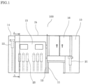
- FIG. 1 is a front view showing a gas insulated switchgear according to Example 1.
- FIG. 2 is a side view showing the gas insulated switchgear according to Example 1.
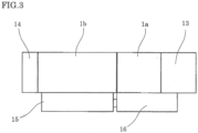
- FIG. 3 is a plan view showing the gas insulated switchgear according to Example 1.
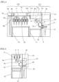
- FIG. 4 is a sectional view taken along the line B-B of FIG. 2 , which shows the gas insulated switchgear according to Example 1.
- FIG. 5 is a sectional view taken along the line A-A of FIG. 1 , which shows the gas insulated switchgear according to Example 1.
- FIG. 6 is a single line connection diagram showing the gas insulated switchgear having the structure of FIG. 1 according to Example 1.
- FIG. 7 is a single line connection diagram showing a gas insulated switchgear having the structure of FIG. 8 according to Example 1.
- FIG. 8 is a front sectional view showing the gas insulated switchgear according to Example 1.
- FIG. 9 is a side sectional view showing the gas insulated switchgear according to Example 1.
- a gas insulated switchgear 100 in this Example 1 includes a basic unit portion 101 including: a first pressure tank 1a in which insulating gas such as hexafluoride (SF6) gas, dry air, and nitrogen is sealed, and is provided with a first opening portion 1a1 at one surface of the first pressure tank 1a; a circuit breaker 2 which is provided with, for example, a vacuum interrupter 2b in the inside, and interrupts a large current; a first disconnecting switch 3a that connects and disconnects a main circuit; a first bushing 4a that connects the main circuit to an external apparatus; a connection conductor 7a that connects the circuit breaker 2 to the first disconnecting switch 3a; and a connection conductor 7b that connects the first disconnecting switch 3a to the first bushing 4a.
- insulating gas such as hexafluoride (SF6) gas, dry air, and nitrogen
- the gas insulated switchgear 100 includes a variable unit portion 102 including: a second pressure tank 1b in which insulating gas such as SF6 gas, dry air, and nitrogen is sealed, and is provided with a second opening portion 1b1 facing the first opening portion 1a1 at one surface of the second pressure tank 1b; three busbars 5 for three phases which are each connected to the circuit breaker 2, and are each horizontally disposed with respect to the front of the gas insulated switchgear 100 and the ground; a second disconnecting switch 3b which is connected to the busbar 5 at one end, and connects and disconnects a main circuit; a third bushing 4b which is connected to the busbar 5 at one end, and is connected to an external apparatus; a second bushing 4c which is connected to the other end portion of the second disconnecting switch 3b, and is connected to an external apparatus; a connection conductor 8a which connects the busbar 5 to the second disconnecting switch 3b; a connection conductor 8b which connects the busbar 5 to the third bushing
- first opening portion 1a1 of the first pressure tank 1a and the second opening portion 1b1 of the second pressure tank 1b are butted and joined facing each other to form into one constitutional body.
- the first pressure tank 1a and the second pressure tank 1b are formed into one constitutional body and the inside thereof can be configured as one gas compartment.
- an insulating spacer or the like that partitions between them does not need to be provided; and therefore, there can be obtained a gas insulated switchgear in which an insulation space necessary for the periphery thereof is not needed, and outline dimensions can be made smaller as a whole.
- the partition between the disconnecting switches does not exist; and therefore, an insulation space necessary for between the partition and the disconnecting switch is not needed and outline dimensions can be made smaller as a whole.
- the first disconnecting switches 3a constitute a three position switch and the second disconnecting switches 3b constitute a three position switch, each three position switch performing three operations of connecting, disconnecting, and grounding.
- the first pressure tank 1a of the basic unit portion 101 is supported by a base frame 11. Furthermore, a circuit breaker operating mechanism 2a of the circuit breaker 2, a first disconnecting switch operating mechanism 3d of the first disconnecting switch 3a, and control components are placed on the outside of the first pressure tank 1a and are accommodated in an compartment 13 for protection.
- the compartment 13 is also supported by a base frame 11. The compartment 13 protects by covering an exposed portion of the first bushing 4a on the outside of the tank and the outer periphery of the cable terminal 21 to be connected to the exposed portion.
- a partition 17 is disposed between a cable installed place and an installed place of the circuit breaker operating mechanism 2a of the circuit breaker 2, the first disconnecting switch operating mechanism 3d, or the like to partition so as to separate both spaces.
- annular current transformer 6 for main circuit current measurement is attached on the outer periphery of the first bushing 4a protruded to the outside of the first pressure tank 1a.
- the second pressure tank 1b of the variable unit portion 102 is supported by a base frame 12. Furthermore, a second disconnecting switch operating mechanism 3e of the second disconnecting switch 3b and control components are placed on the outside of the tank and are accommodated in an compartment 15 in order to protect an internal structure by separating from external environment of the gas insulated switchgear 100.
- the compartment 15 is also supported by the base frame 12.
- the compartment 15 also protects an exposed portion of the second bushing 4c on the outside of the second pressure tank 1b and a cable terminal 23 to be connected to the exposed portion. Then, in order to avoid spreading the influence of an unexpected fault, a partition 18 is disposed between a cable installed place and an installed place of the second disconnecting switch operating mechanism 3e and the like to separate spaces of the second disconnecting switch operating mechanism 3e portion and the cable connection portion.
- the compartment 13 and the compartment 15 are connected to a control box 16 to be a structure that can dispose necessary control circuits.
- the control box 16 is supported by the base frame 11.
- FIG. 6 is a single line connection diagram and the most right side circuit of FIG. 6 shows a circuit of the basic unit portion 101. Circuits other than that and a busbar that commonly connects those circuits show a circuit of the variable unit portion 102.
- the circuit of the basic unit portion 101 is a generally this circuit and fulfills a function as a circuit to be connected to a drawing-in portion.
- the circuit of the variable unit portion 102 is fluctuated by: the number of circuits in which the gas insulated switchgear 100 is externally connected, that is, by the sum of one drawing-in circuit and the number of drawing-out circuits; and switching apparatuses, measurement devices, and the number of connection cables which are to be accommodated.
- the shapes of the installed apparatus of the variable unit portion 102 and the second pressure tank 1b are changed in accordance with fluctuating elements.
- FIG. 7 , FIG. 8, and FIG. 9 show a single line diagram, a front sectional view, and a side sectional view, respectively.
- FIG. 7 shows a circuit in which one of the number of circuits is reduced from FIG. 6 and the number of connection cables is changed from one to two.
- the structure of the gas insulated switchgear 100 in this case becomes as shown in FIG. 8 and FIG. 9 .
- the cable terminal 23 is increased to two branches; and in the side sectional view of FIG. 9 , it becomes a structure in which the third bushing 4b and the cable terminal 22 are deleted.
- the insulation distance between the respective circuits, especially, between the circuits in the variable unit portion 102 can be reduced by enclosing a plurality of circuits in one gas compartment.
- FIG. 4 there exists only an insulation space between each other's apparatuses in between two second disconnecting switches 3b. If, in the case of the gas insulated switchgear in which the respective circuits are individually configured as disclosed in Patent Document 2, there exists a grounded partition (pressure tank wall) between the apparatuses; and an insulating space needs to be provided between each apparatus and the partition.
- Example 1 These partitions are deleted in Example 1 and a plurality of circuits is accommodated in one gas compartment, whereby reduction in outline dimensions of the gas insulated switchgear 100, especially, width dimension can be achieved.
- the gas insulated switchgear 100 is divided into two portions of the basic unit portion 101 and the variable unit portion 102, whereby the basic unit portion 101 can be manufactured as a standard unit in any application circuit. Therefore, planned production such as stocking of members can be made and cost reduction can be achieved.
- FIG. 4 it is structured such that the connection circuit excluding the second disconnecting switches 3b of the variable unit portion 102 is directly connected to the busbar 5, and the dimensions and structure of the second pressure tank 1b are made common to the case where the circuit excluding the second disconnecting switches 3b does not exist ( FIG. 8 ), whereby types of the pressure tanks are reduced and planned production and cost reduction can be achieved.
- the control box 16 is formed into a structure capable of accommodating control devices necessary for the maximum condition of an application circuit of the gas insulated switchgear 100, and it is structured such that the control box 16 is supported by only the base frame 11, whereby the control box 16 can be made common even when the circuit condition is changed and planned production and cost reduction of the control box 16 can be achieved.
- the gas insulated switchgear 100 is divided into two portions of the basic unit portion 101 and the variable unit portion 102, whereby the basic unit portion 101 can be manufactured as a standard unit in any application circuit. Therefore, planned production such as stocking of members can be made and cost reduction can be achieved.
- FIG. 10 is a front sectional view showing a gas insulated switchgear according to the Embodiment of the present invention.
- a first opening portion 1c1 is made small by providing an inclined portion 1c2 in which a part of the bottom surface of a first pressure tank 1c of a basic unit portion 101 is made incline; a second opening portion 1d1 of a second pressure tank 1d of a variable unit portion 102 is made small by adjusting to the first opening portion 1c1; and the first opening portion 1c1 of the first pressure tank 1c of the basic unit portion 101 and the second opening portion 1d1 of the second pressure tank 1d of the variable unit portion 102 are butted and joined.
- the shape of the first pressure tank 1c is changed so that a space where there exists no installed apparatus is reduced, whereby a gas compartment space can be reduced and therefore the amount of usage of insulating gas can be reduced. Furthermore, the first opening portion 1c1 and the second opening portion 1d1 are made small, whereby reliability of an airtight sealing portion is improved and fastening work in joining the unit portions can be reduced.
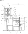
- FIG. 11 is a side sectional view showing a gas insulated switchgear according to Example 2.
- FIG. 12 is a plan sectional view showing a gas insulated switchgear according to Example 2.
- a second opening portion 1f1 of a variable unit portion 102 having a second pressure tank 1f is butted and joined to a first opening portion 1e1 on a rear portion of a basic unit portion 101 having a first pressure tank 1e to form into one constitutional body.
- a second disconnecting switch 3b whose one end is connected to one end portion of a circuit breaker 2 and is branched and connected for each circuit from each of vertically extended three busbars for three phases 5, and a second bushing 4c and a cable terminal 23 which are connected to the end of the second disconnecting switch 3b are arranged upward in a pile-up direction for each circuit.
- a cable terminal 22 is connected at an end portion of a connection conductor led out to the left direction from one end of the circuit breaker 2 via a third bushing 4b which passes through and is attached to a wall portion of the second pressure tank 1f.
- a main circuit branched from the second disconnecting switch 3b passes through a wall of the second pressure tank 1f by the second bushing 4c and one end portion thereof is connected to the cable terminal 23.
- one shown by a circular dashed line at the midpoint of the cable terminal 23 shows a cable that is extended downward.
- vertically extended cables for three phases do not interfere with each other by shifting the second bushings 4c for three phases from side to side and therefore it becomes easy to connect the cable terminal 23 to the second bushing 4c.
- busbars 5 are vertically extended and branch circuits therefrom are configured so as to vertically pile-up, whereby, for example, like a tower for a wind turbine, such a configuration can easily cope with a case where restriction in a ceiling direction is relatively small although the installation area of the gas insulated switchgear is narrow.
- branch main circuits connected correspondingly to respective circuits are arranged so as to vertically pile-up even when the number of circuits of electric power lines that connect between towers for respective wind turbines is increased, whereby it can easily cope with circuit connection of a plurality of electric power lines even when the installation area is narrow.
- Example 3 there is shown an example configured such that the busbars 5 are vertically extended and the branch circuits therefrom are vertically piled up; however, the example is not limited to this; and even when the busbars 5 are not arranged in a vertical direction, but, for example, are arranged with being inclined vertically (i.e. obliquely), such a configuration can easily cope with connection of a plurality of circuits even when the installation area is narrow although the installation area increases as compared to the above case example.
- the present invention can freely combine the respective embodiments and appropriately modify and/or omit the respective embodiments within the scope of the present invention, as defined by the claims.
- the present invention is suitable to achieve the gas insulated switchgear in which the first opening portion of the first pressure tank and the second opening portion of the second pressure tank are butted and joined facing each other to form into one constitutional body and the inside thereof can be configured as one gas compartment.
Landscapes
- Engineering & Computer Science (AREA)
- Power Engineering (AREA)
- Gas-Insulated Switchgears (AREA)
Claims (9)
- Gasisolierte Schaltanlage (100), die das Folgende aufweist:einen Bereich (101) für eine Basiseinheit, der durch eine Standardeinheit konfiguriert ist, und einen Bereich (102) für eine variable Einheit,wobei der Bereich (101) für eine Basiseinheit das Folgende aufweist:- einen ersten Druckbehälter (1c), in dem Isoliergas eingeschlossen ist, und einen ersten Öffnungsbereich (1c1), der in mindestens einer Oberfläche des ersten Druckbehälters (1c) angeordnet ist;- einen Leistungsschalter (2), der im Inneren des ersten Druckbehälters (1c) angeordnet ist und dazu konfiguriert ist, einen hohen Strom zu unterbrechen;- einen ersten Trennschalter (3a), der mit dem Leistungsschalter (2) verbunden ist und dazu konfiguriert ist, einen Hauptstromkreis zu unterbrechen; und- eine erste Durchführung (4a), die dazu konfiguriert ist, den Hauptstromkreis mit einem externen Gerät zu verbinden, und wobei der Bereich (102) für eine variable Einheit das Folgende aufweist:- eine Sammelschiene (5), die mit einem Anschluss der einen Seite des Leistungsschalters (2) verbunden ist;- einen zweiten Druckbehälter (1d), in dem Isoliergas eingeschlossen ist, wobei ein zweiter Öffnungsbereich (1d1), der dem ersten Öffnungsbereich (1c1) zugewandt ist, in mindestens einer Oberfläche des zweiten Druckbehälters (1d) angeordnet ist, wobei die Sammelschiene (5) in dem zweiten Druckbehälter (1d) angeordnet ist;- eine oder mehrere zweite Durchführungen (4c), die durch eine Wand des zweiten Druckbehälters (1d) verlaufen und dazu konfiguriert sind, einen internen Hauptstromkreis des zweiten Druckbehälters (1d) mit einem externen Gerät zu verbinden; und- einen oder eine Vielzahl von zweiten Trennschaltern (3b), die zwischen der Sammelschiene (5) und der einen oder den mehreren zweiten Durchführungen (4c) angeordnet sind und den Hauptstromkreis unterbrechen,dadurch gekennzeichnet,dass der erste Öffnungsbereich (1c1) des ersten Druckbehälters (1c) und der zweite Öffnungsbereich (1d1) des zweiten Druckbehälters (1d) verjüngt und einander zugewandt verbunden sind, um einen einzigen konstituierten Körper zu bilden, sodass das Innere des ersten Druckbehälters (1c) und des zweiten Druckbehälters (1d) als ein einziger Gasraum konfiguriert ist,wobei der erste Öffnungsbereich (1c1) verkleinert ist, indem die Bodenfläche (1c2) des ersten Druckbehälters (1c) des Bereichs (101) für eine Basiseinheit geneigt ausgebildet ist, und der zweite Öffnungsbereich (1d1) des zweiten Druckbehälters (1d) des Bereichs (102) für eine variable Einheit durch Anpassen an den ersten Öffnungsbereich (1c1) verkleinert ist.
- Gasisolierte Schaltanlage (100) nach Anspruch 1,
die ferner das Folgende aufweist:
eine dritte Durchführung (4b), die durch eine Wand des zweiten Druckbehälters (1d) verläuft, an einem Ende mit der Sammelschiene (5) verbunden ist und dazu konfiguriert ist, den internen Hauptstromkreis des zweiten Druckbehälters (1d) mit einem externen Gerät zu verbinden. - Gasisolierte Schaltanlage (100) nach Anspruch 1 oder 2,
wobei die Sammelschiene (5) horizontal zum Boden angeordnet ist. - Gasisolierte Schaltanlage (100) nach Anspruch 1 oder 2,
wobei die Sammelschiene (5) vertikal zum Boden angeordnet ist. - Gasisolierte Schaltanlage (100) nach einem der Ansprüche 2 bis 4, wobei die Sammelschiene (5) direkt mit der dritten Durchführung (4b) verbunden ist.
- Gasisolierte Schaltanlage (100) nach Anspruch 2 bis 5,
wobei die dritte Durchführung (4b), die mit der Sammelschiene (5) zu verbinden ist, an einer Seitenwand des zweiten Druckbehälters (1d) angeordnet ist. - Gasisolierte Schaltanlage (100) nach einem der Ansprüche 1 bis 6, wobei die Form des ersten Druckbehälters (1c) unabhängig vom Vorhandensein oder Nichtvorhandensein der dritten Durchführung (4b), die mit der Sammelschiene (5) zu verbinden ist, gleich ist.
- Gasisolierte Schaltanlage (100) nach einem der Ansprüche 1 bis 7, wobei die ersten Trennschalter (3a) einen Schalter mit drei Stellungen bilden, der die drei Vorgänge des Verbindens, Trennens und Erdens durchführt.
- Gasisolierte Schaltanlage (100) nach einem der Ansprüche 1 bis 8, wobei die zweiten Trennschalter (3b) einen Schalter mit drei Stellungen bilden, der die drei Vorgänge des Verbindens, Trennens und Erdens durchführt.
Applications Claiming Priority (1)
| Application Number | Priority Date | Filing Date | Title |
|---|---|---|---|
| PCT/JP2015/060471 WO2016157495A1 (ja) | 2015-04-02 | 2015-04-02 | ガス絶縁スイッチギヤ |
Publications (3)
| Publication Number | Publication Date |
|---|---|
| EP3280016A1 EP3280016A1 (de) | 2018-02-07 |
| EP3280016A4 EP3280016A4 (de) | 2018-11-07 |
| EP3280016B1 true EP3280016B1 (de) | 2025-01-01 |
Family
ID=56015209
Family Applications (1)
| Application Number | Title | Priority Date | Filing Date |
|---|---|---|---|
| EP15887642.5A Active EP3280016B1 (de) | 2015-04-02 | 2015-04-02 | Gasisoliertes schaltgetriebe |
Country Status (5)
| Country | Link |
|---|---|
| US (1) | US10297987B2 (de) |
| EP (1) | EP3280016B1 (de) |
| JP (1) | JP5921783B1 (de) |
| CN (1) | CN107431338B (de) |
| WO (1) | WO2016157495A1 (de) |
Families Citing this family (4)
| Publication number | Priority date | Publication date | Assignee | Title |
|---|---|---|---|---|
| WO2022085544A1 (ja) * | 2020-10-22 | 2022-04-28 | Agc株式会社 | 電気設備 |
| DE102022200005A1 (de) * | 2022-01-03 | 2023-07-06 | Siemens Energy Global GmbH & Co. KG | Windkraftanlage und Verschaltung von Windkraftanlagen |
| US12476441B2 (en) * | 2022-08-24 | 2025-11-18 | Siemens Energy Global GmbH & Co. KG | Arrangement of a current transformer core at an interface with a conical connector |
| JP7566213B1 (ja) * | 2024-01-24 | 2024-10-11 | 三菱電機株式会社 | ガス絶縁開閉装置 |
Family Cites Families (18)
| Publication number | Priority date | Publication date | Assignee | Title |
|---|---|---|---|---|
| JPS6237379Y2 (de) * | 1980-04-01 | 1987-09-24 | ||
| IN157109B (de) | 1981-01-24 | 1986-01-18 | Brush Switchgear | |
| DE3429711A1 (de) * | 1983-10-27 | 1985-05-09 | Fritz Driescher KG Spezialfabrik für Elektrizitätswerksbedarf GmbH & Co, 5144 Wegberg | Gasisolierte mittelspannungsschaltanlage |
| JPH02290111A (ja) * | 1989-04-28 | 1990-11-30 | Mitsubishi Electric Corp | ガス絶縁形配電盤 |
| JP3688805B2 (ja) * | 1996-05-31 | 2005-08-31 | 三菱電機株式会社 | ガス絶縁開閉装置 |
| US5898565A (en) * | 1996-06-27 | 1999-04-27 | Mitsubishi Denki Kabushiki Kaisha | Gas insulated switchgear apparatus |
| JP2002159109A (ja) * | 2000-11-20 | 2002-05-31 | Mitsubishi Electric Corp | ガス絶縁開閉装置 |
| US7688595B2 (en) * | 2002-03-13 | 2010-03-30 | Pioneer Energy Products, Llc | Shielded cable entry ports and assemblies |
| JP4334852B2 (ja) | 2002-10-31 | 2009-09-30 | 三菱電機株式会社 | ガス絶縁スイッチギヤ |
| TWI228339B (en) * | 2002-11-06 | 2005-02-21 | Mitsubishi Electric Corp | Metal-enclosed switchgear |
| JP4237591B2 (ja) * | 2003-09-17 | 2009-03-11 | 株式会社日立製作所 | ガス絶縁開閉装置 |
| KR101153478B1 (ko) * | 2008-04-07 | 2012-06-11 | 미쓰비시덴키 가부시키가이샤 | 진공 차단기 및 이를 사용한 가스 절연 개폐 장치 |
| CN101741029B (zh) * | 2008-11-04 | 2012-09-05 | 上海天灵开关厂有限公司 | 全充气全绝缘电缆分接箱 |
| HUE030140T2 (hu) * | 2010-01-18 | 2017-04-28 | Abb Technology Ag | Befogadó modul megszakítókkal gáz-szigetelésû kapcsolóberendezéshez |
| US8451589B2 (en) * | 2010-06-07 | 2013-05-28 | Abd El & Larson Holdings LLC | Multi-access switchgear assembly |
| EP2958205B1 (de) * | 2013-02-13 | 2019-03-27 | Mitsubishi Electric Corporation | Gasisolierte schaltanlage |
| CN106415958B (zh) * | 2014-06-06 | 2020-02-07 | 三菱电机株式会社 | 开关机构 |
| CN204089010U (zh) * | 2014-08-22 | 2015-01-07 | Abb技术有限公司 | 多台开关柜共用母线室的气体绝缘开关柜 |
-
2015
- 2015-04-02 WO PCT/JP2015/060471 patent/WO2016157495A1/ja not_active Ceased
- 2015-04-02 EP EP15887642.5A patent/EP3280016B1/de active Active
- 2015-04-02 CN CN201580078395.XA patent/CN107431338B/zh active Active
- 2015-04-02 US US15/542,147 patent/US10297987B2/en active Active
- 2015-04-02 JP JP2015539309A patent/JP5921783B1/ja active Active
Also Published As
| Publication number | Publication date |
|---|---|
| JPWO2016157495A1 (ja) | 2017-04-27 |
| EP3280016A1 (de) | 2018-02-07 |
| US20180269663A1 (en) | 2018-09-20 |
| EP3280016A4 (de) | 2018-11-07 |
| US10297987B2 (en) | 2019-05-21 |
| JP5921783B1 (ja) | 2016-05-24 |
| CN107431338B (zh) | 2020-10-30 |
| WO2016157495A1 (ja) | 2016-10-06 |
| CN107431338A (zh) | 2017-12-01 |
Similar Documents
| Publication | Publication Date | Title |
|---|---|---|
| EP3062403B1 (de) | Gasisolierte schaltanlage | |
| JP4512648B2 (ja) | スイッチギヤ | |
| KR20100017368A (ko) | 고전압 개폐기 | |
| EP2958205B1 (de) | Gasisolierte schaltanlage | |
| US9472926B2 (en) | Gas-insulated switchgear arrangement | |
| CN102428535A (zh) | 电气式功率开关和带有功率开关的开关板 | |
| EP3280016B1 (de) | Gasisoliertes schaltgetriebe | |
| US20130201607A1 (en) | Pressurised gas-insulated multi-phase control panel | |
| CN101617450B (zh) | 高压开关设备 | |
| JP6398651B2 (ja) | スイッチギヤ | |
| JP2010022139A (ja) | キュービクル形ガス絶縁開閉装置 | |
| HK1225521B (en) | Gas-insulated switchgear | |
| HK1225521A1 (en) | Gas-insulated switchgear | |
| HK1134379B (en) | Switchgear | |
| JPH0832124B2 (ja) | ガス絶縁開閉装置 |
Legal Events
| Date | Code | Title | Description |
|---|---|---|---|
| STAA | Information on the status of an ep patent application or granted ep patent |
Free format text: STATUS: THE INTERNATIONAL PUBLICATION HAS BEEN MADE |
|
| PUAI | Public reference made under article 153(3) epc to a published international application that has entered the european phase |
Free format text: ORIGINAL CODE: 0009012 |
|
| STAA | Information on the status of an ep patent application or granted ep patent |
Free format text: STATUS: REQUEST FOR EXAMINATION WAS MADE |
|
| 17P | Request for examination filed |
Effective date: 20170929 |
|
| AK | Designated contracting states |
Kind code of ref document: A1 Designated state(s): AL AT BE BG CH CY CZ DE DK EE ES FI FR GB GR HR HU IE IS IT LI LT LU LV MC MK MT NL NO PL PT RO RS SE SI SK SM TR |
|
| AX | Request for extension of the european patent |
Extension state: BA ME |
|
| DAV | Request for validation of the european patent (deleted) | ||
| DAX | Request for extension of the european patent (deleted) | ||
| A4 | Supplementary search report drawn up and despatched |
Effective date: 20181009 |
|
| RIC1 | Information provided on ipc code assigned before grant |
Ipc: H02B 13/035 20060101AFI20181003BHEP Ipc: H01H 33/12 20060101ALI20181003BHEP Ipc: H02B 13/045 20060101ALI20181003BHEP Ipc: H02B 7/06 20060101ALN20181003BHEP |
|
| STAA | Information on the status of an ep patent application or granted ep patent |
Free format text: STATUS: EXAMINATION IS IN PROGRESS |
|
| 17Q | First examination report despatched |
Effective date: 20200918 |
|
| GRAP | Despatch of communication of intention to grant a patent |
Free format text: ORIGINAL CODE: EPIDOSNIGR1 |
|
| STAA | Information on the status of an ep patent application or granted ep patent |
Free format text: STATUS: GRANT OF PATENT IS INTENDED |
|
| RIC1 | Information provided on ipc code assigned before grant |
Ipc: H02B 7/06 20060101ALN20240612BHEP Ipc: H01H 33/12 20060101ALI20240612BHEP Ipc: H02B 13/045 20060101ALI20240612BHEP Ipc: H02B 13/035 20060101AFI20240612BHEP |
|
| RIC1 | Information provided on ipc code assigned before grant |
Ipc: H02B 7/06 20060101ALN20240618BHEP Ipc: H01H 33/12 20060101ALI20240618BHEP Ipc: H02B 13/045 20060101ALI20240618BHEP Ipc: H02B 13/035 20060101AFI20240618BHEP |
|
| INTG | Intention to grant announced |
Effective date: 20240704 |
|
| GRAS | Grant fee paid |
Free format text: ORIGINAL CODE: EPIDOSNIGR3 |
|
| GRAA | (expected) grant |
Free format text: ORIGINAL CODE: 0009210 |
|
| STAA | Information on the status of an ep patent application or granted ep patent |
Free format text: STATUS: THE PATENT HAS BEEN GRANTED |
|
| AK | Designated contracting states |
Kind code of ref document: B1 Designated state(s): AL AT BE BG CH CY CZ DE DK EE ES FI FR GB GR HR HU IE IS IT LI LT LU LV MC MK MT NL NO PL PT RO RS SE SI SK SM TR |
|
| REG | Reference to a national code |
Ref country code: GB Ref legal event code: FG4D |
|
| REG | Reference to a national code |
Ref country code: CH Ref legal event code: EP |
|
| REG | Reference to a national code |
Ref country code: DE Ref legal event code: R096 Ref document number: 602015090787 Country of ref document: DE |
|
| REG | Reference to a national code |
Ref country code: IE Ref legal event code: FG4D |
|
| REG | Reference to a national code |
Ref country code: LT Ref legal event code: MG9D |
|
| REG | Reference to a national code |
Ref country code: NL Ref legal event code: MP Effective date: 20250101 |
|
| REG | Reference to a national code |
Ref country code: AT Ref legal event code: MK05 Ref document number: 1757298 Country of ref document: AT Kind code of ref document: T Effective date: 20250101 |
|
| PG25 | Lapsed in a contracting state [announced via postgrant information from national office to epo] |
Ref country code: NL Free format text: LAPSE BECAUSE OF FAILURE TO SUBMIT A TRANSLATION OF THE DESCRIPTION OR TO PAY THE FEE WITHIN THE PRESCRIBED TIME-LIMIT Effective date: 20250101 |
|
| PG25 | Lapsed in a contracting state [announced via postgrant information from national office to epo] |
Ref country code: FI Free format text: LAPSE BECAUSE OF FAILURE TO SUBMIT A TRANSLATION OF THE DESCRIPTION OR TO PAY THE FEE WITHIN THE PRESCRIBED TIME-LIMIT Effective date: 20250101 |
|
| PG25 | Lapsed in a contracting state [announced via postgrant information from national office to epo] |
Ref country code: PL Free format text: LAPSE BECAUSE OF FAILURE TO SUBMIT A TRANSLATION OF THE DESCRIPTION OR TO PAY THE FEE WITHIN THE PRESCRIBED TIME-LIMIT Effective date: 20250101 |
|
| PGFP | Annual fee paid to national office [announced via postgrant information from national office to epo] |
Ref country code: DE Payment date: 20250305 Year of fee payment: 11 |
|
| PG25 | Lapsed in a contracting state [announced via postgrant information from national office to epo] |
Ref country code: ES Free format text: LAPSE BECAUSE OF FAILURE TO SUBMIT A TRANSLATION OF THE DESCRIPTION OR TO PAY THE FEE WITHIN THE PRESCRIBED TIME-LIMIT Effective date: 20250101 |
|
| PG25 | Lapsed in a contracting state [announced via postgrant information from national office to epo] |
Ref country code: IS Free format text: LAPSE BECAUSE OF FAILURE TO SUBMIT A TRANSLATION OF THE DESCRIPTION OR TO PAY THE FEE WITHIN THE PRESCRIBED TIME-LIMIT Effective date: 20250501 Ref country code: NO Free format text: LAPSE BECAUSE OF FAILURE TO SUBMIT A TRANSLATION OF THE DESCRIPTION OR TO PAY THE FEE WITHIN THE PRESCRIBED TIME-LIMIT Effective date: 20250401 |
|
| PG25 | Lapsed in a contracting state [announced via postgrant information from national office to epo] |
Ref country code: HR Free format text: LAPSE BECAUSE OF FAILURE TO SUBMIT A TRANSLATION OF THE DESCRIPTION OR TO PAY THE FEE WITHIN THE PRESCRIBED TIME-LIMIT Effective date: 20250101 |
|
| PG25 | Lapsed in a contracting state [announced via postgrant information from national office to epo] |
Ref country code: LV Free format text: LAPSE BECAUSE OF FAILURE TO SUBMIT A TRANSLATION OF THE DESCRIPTION OR TO PAY THE FEE WITHIN THE PRESCRIBED TIME-LIMIT Effective date: 20250101 Ref country code: PT Free format text: LAPSE BECAUSE OF FAILURE TO SUBMIT A TRANSLATION OF THE DESCRIPTION OR TO PAY THE FEE WITHIN THE PRESCRIBED TIME-LIMIT Effective date: 20250502 |
|
| PG25 | Lapsed in a contracting state [announced via postgrant information from national office to epo] |
Ref country code: GR Free format text: LAPSE BECAUSE OF FAILURE TO SUBMIT A TRANSLATION OF THE DESCRIPTION OR TO PAY THE FEE WITHIN THE PRESCRIBED TIME-LIMIT Effective date: 20250402 Ref country code: BG Free format text: LAPSE BECAUSE OF FAILURE TO SUBMIT A TRANSLATION OF THE DESCRIPTION OR TO PAY THE FEE WITHIN THE PRESCRIBED TIME-LIMIT Effective date: 20250101 |
|
| PG25 | Lapsed in a contracting state [announced via postgrant information from national office to epo] |
Ref country code: AT Free format text: LAPSE BECAUSE OF FAILURE TO SUBMIT A TRANSLATION OF THE DESCRIPTION OR TO PAY THE FEE WITHIN THE PRESCRIBED TIME-LIMIT Effective date: 20250101 |
|
| PG25 | Lapsed in a contracting state [announced via postgrant information from national office to epo] |
Ref country code: CZ Free format text: LAPSE BECAUSE OF FAILURE TO SUBMIT A TRANSLATION OF THE DESCRIPTION OR TO PAY THE FEE WITHIN THE PRESCRIBED TIME-LIMIT Effective date: 20250101 |
|
| PG25 | Lapsed in a contracting state [announced via postgrant information from national office to epo] |
Ref country code: SE Free format text: LAPSE BECAUSE OF FAILURE TO SUBMIT A TRANSLATION OF THE DESCRIPTION OR TO PAY THE FEE WITHIN THE PRESCRIBED TIME-LIMIT Effective date: 20250101 |
|
| P01 | Opt-out of the competence of the unified patent court (upc) registered |
Free format text: CASE NUMBER: UPC_APP_4857_3280016/2025 Effective date: 20250827 |
|
| REG | Reference to a national code |
Ref country code: DE Ref legal event code: R097 Ref document number: 602015090787 Country of ref document: DE |
|
| PG25 | Lapsed in a contracting state [announced via postgrant information from national office to epo] |
Ref country code: SM Free format text: LAPSE BECAUSE OF FAILURE TO SUBMIT A TRANSLATION OF THE DESCRIPTION OR TO PAY THE FEE WITHIN THE PRESCRIBED TIME-LIMIT Effective date: 20250101 |
|
| PG25 | Lapsed in a contracting state [announced via postgrant information from national office to epo] |
Ref country code: DK Free format text: LAPSE BECAUSE OF FAILURE TO SUBMIT A TRANSLATION OF THE DESCRIPTION OR TO PAY THE FEE WITHIN THE PRESCRIBED TIME-LIMIT Effective date: 20250101 |
|
| PG25 | Lapsed in a contracting state [announced via postgrant information from national office to epo] |
Ref country code: EE Free format text: LAPSE BECAUSE OF FAILURE TO SUBMIT A TRANSLATION OF THE DESCRIPTION OR TO PAY THE FEE WITHIN THE PRESCRIBED TIME-LIMIT Effective date: 20250101 |
|
| PG25 | Lapsed in a contracting state [announced via postgrant information from national office to epo] |
Ref country code: RO Free format text: LAPSE BECAUSE OF FAILURE TO SUBMIT A TRANSLATION OF THE DESCRIPTION OR TO PAY THE FEE WITHIN THE PRESCRIBED TIME-LIMIT Effective date: 20250101 |
|
| PG25 | Lapsed in a contracting state [announced via postgrant information from national office to epo] |
Ref country code: SK Free format text: LAPSE BECAUSE OF FAILURE TO SUBMIT A TRANSLATION OF THE DESCRIPTION OR TO PAY THE FEE WITHIN THE PRESCRIBED TIME-LIMIT Effective date: 20250101 |
|
| PLBE | No opposition filed within time limit |
Free format text: ORIGINAL CODE: 0009261 |
|
| STAA | Information on the status of an ep patent application or granted ep patent |
Free format text: STATUS: NO OPPOSITION FILED WITHIN TIME LIMIT |
|
| REG | Reference to a national code |
Ref country code: CH Ref legal event code: L10 Free format text: ST27 STATUS EVENT CODE: U-0-0-L10-L00 (AS PROVIDED BY THE NATIONAL OFFICE) Effective date: 20251112 |
|
| REG | Reference to a national code |
Ref country code: CH Ref legal event code: H13 Free format text: ST27 STATUS EVENT CODE: U-0-0-H10-H13 (AS PROVIDED BY THE NATIONAL OFFICE) Effective date: 20251125 |
|
| 26N | No opposition filed |
Effective date: 20251002 |
|
| PG25 | Lapsed in a contracting state [announced via postgrant information from national office to epo] |
Ref country code: LU Free format text: LAPSE BECAUSE OF NON-PAYMENT OF DUE FEES Effective date: 20250402 |
|
| PG25 | Lapsed in a contracting state [announced via postgrant information from national office to epo] |
Ref country code: MC Free format text: LAPSE BECAUSE OF FAILURE TO SUBMIT A TRANSLATION OF THE DESCRIPTION OR TO PAY THE FEE WITHIN THE PRESCRIBED TIME-LIMIT Effective date: 20250101 |
|
| GBPC | Gb: european patent ceased through non-payment of renewal fee |
Effective date: 20250402 |
|
| REG | Reference to a national code |
Ref country code: BE Ref legal event code: MM Effective date: 20250430 |
|
| PG25 | Lapsed in a contracting state [announced via postgrant information from national office to epo] |
Ref country code: GB Free format text: LAPSE BECAUSE OF NON-PAYMENT OF DUE FEES Effective date: 20250402 |
|
| PG25 | Lapsed in a contracting state [announced via postgrant information from national office to epo] |
Ref country code: BE Free format text: LAPSE BECAUSE OF NON-PAYMENT OF DUE FEES Effective date: 20250430 |
|
| PG25 | Lapsed in a contracting state [announced via postgrant information from national office to epo] |
Ref country code: CH Free format text: LAPSE BECAUSE OF NON-PAYMENT OF DUE FEES Effective date: 20250430 |
|
| PG25 | Lapsed in a contracting state [announced via postgrant information from national office to epo] |
Ref country code: IE Free format text: LAPSE BECAUSE OF NON-PAYMENT OF DUE FEES Effective date: 20250402 |
|
| PGFP | Annual fee paid to national office [announced via postgrant information from national office to epo] |
Ref country code: IT Payment date: 20260320 Year of fee payment: 12 |
|
| PGFP | Annual fee paid to national office [announced via postgrant information from national office to epo] |
Ref country code: FR Payment date: 20260309 Year of fee payment: 12 |