EP3280136A1 - Système de projection, dispositif de projecteur, et programme - Google Patents
Système de projection, dispositif de projecteur, et programme Download PDFInfo
- Publication number
- EP3280136A1 EP3280136A1 EP16772050.7A EP16772050A EP3280136A1 EP 3280136 A1 EP3280136 A1 EP 3280136A1 EP 16772050 A EP16772050 A EP 16772050A EP 3280136 A1 EP3280136 A1 EP 3280136A1
- Authority
- EP
- European Patent Office
- Prior art keywords
- image
- projection
- point
- plane
- unit
- Prior art date
- Legal status (The legal status is an assumption and is not a legal conclusion. Google has not performed a legal analysis and makes no representation as to the accuracy of the status listed.)
- Granted
Links
Images










Classifications
-
- G—PHYSICS
- G06—COMPUTING OR CALCULATING; COUNTING
- G06T—IMAGE DATA PROCESSING OR GENERATION, IN GENERAL
- G06T5/00—Image enhancement or restoration
- G06T5/80—Geometric correction
-
- H—ELECTRICITY
- H04—ELECTRIC COMMUNICATION TECHNIQUE
- H04N—PICTORIAL COMMUNICATION, e.g. TELEVISION
- H04N9/00—Details of colour television systems
- H04N9/12—Picture reproducers
- H04N9/31—Projection devices for colour picture display, e.g. using electronic spatial light modulators [ESLM]
- H04N9/3179—Video signal processing therefor
- H04N9/3185—Geometric adjustment, e.g. keystone or convergence
-
- G—PHYSICS
- G06—COMPUTING OR CALCULATING; COUNTING
- G06T—IMAGE DATA PROCESSING OR GENERATION, IN GENERAL
- G06T3/00—Geometric image transformations in the plane of the image
- G06T3/60—Rotation of whole images or parts thereof
-
- H—ELECTRICITY
- H04—ELECTRIC COMMUNICATION TECHNIQUE
- H04N—PICTORIAL COMMUNICATION, e.g. TELEVISION
- H04N9/00—Details of colour television systems
- H04N9/12—Picture reproducers
- H04N9/31—Projection devices for colour picture display, e.g. using electronic spatial light modulators [ESLM]
- H04N9/3191—Testing thereof
-
- H—ELECTRICITY
- H04—ELECTRIC COMMUNICATION TECHNIQUE
- H04N—PICTORIAL COMMUNICATION, e.g. TELEVISION
- H04N9/00—Details of colour television systems
- H04N9/12—Picture reproducers
- H04N9/31—Projection devices for colour picture display, e.g. using electronic spatial light modulators [ESLM]
- H04N9/3191—Testing thereof
- H04N9/3194—Testing thereof including sensor feedback
Definitions
- the present invention relates to a technique for appropriately displaying an image (video) projected by a projection-type projector apparatus.
- forward inclined plane refers to a plane that is obtained by rotating a plane parallel to a floor around a rotation axis, which is a straight line parallel to the floor (or a straight line parallel to a straight line passing through the left eye viewpoint and right eye viewpoint of a user), and that does not incline either in the left direction or in the right direction as viewed from the user, and that inclines forward (in the direction toward the user).
- a second aspect of the present invention provides the projection system of the first aspect of the present invention in which the test image is an image including a vertical reference line extending in a vertical direction in an image in a state of being displayed on a display screen.
- the projection system projects a test image, in which the upper portion can be recognized when the image is displayed, onto the projection plane (e.g., a horizontal projection plane, such as a horizontal ceiling plane) that is parallel to the straight line connecting the left eye viewpoint and right eye viewpoint of the user.
- the projection system (1) performs processing for rotating the projected image in the projection plane and then (2) performs the keystone correction processing on the image projected onto the projection plane, thereby allowing for eliminating (reducing) geometric distortion in the image projected onto the projection plane.
- the projection system easily and appropriately eliminates (reduces) geometric distortion of an image projected on the projection plane (e.g., a horizontal projection plane, such as a horizontal ceiling plane) that is parallel to the straight line connecting the left eye viewpoint and right eye viewpoint of the user without using a device having a photographing function.
- a horizontal projection plane such as a horizontal ceiling plane
- the wording "geometric distortion occurring in the direction orthogonal to the vertical reference line is reduced” includes a concept that a difference between the length (the width) of the projected image in the direction orthogonal to the vertical reference line in the upper portion of the image (the upper portion in the vertical direction when the image is displayed) and the length (the width) of the projected image in the direction orthogonal to the vertical reference line in the lower portion of the image (the lower portion in the vertical direction when the image is displayed) becomes small.
- the sliest adjustment unit performs the above-described adjustment processing to correct errors that occurs in the three-dimensional shape measurement processing, for example, thereby allowing for performing even more accurate image projection processing (processing for reducing geometric distortion of the image).
- a fourth aspect of the present invention provides the projection system of the second or third aspect of the present invention in which the test image includes a pattern capable of distinguishing the upper portion of the test image in a state of being displayed on a display screen.
- a seventh aspect of the present invention provides the projector apparatus used in the projection system of one of the first to fifth aspects of the present invention.
- the projector apparatus includes the projection unit and the projected image adjustment unit.
- the projection method includes a projection step, a three-dimensional shape measurement step, a step configured to generate a control signal based on operation of the user, and a projected image adjustment step.
- the projection step is configured to project a test image onto the projection plane.
- a tenth aspect of the invention provides a projection system in which an inclined plane with respect to a plane that is parallel to a plane including a left eye viewpoint and a right eye viewpoint and is a common tangent plane of the right eye cornea and the left eye cornea is set as a projection plane and an image is projected such that geometric image distortion is reduced as viewed from a user's viewpoint.
- the projection system includes a projection unit, a three-dimensional shape measurement unit, a controller, and a projected image adjustment unit.
- the three-dimensional shape measurement unit is configured to measure a three-dimensional shape of the projection plane.
- the controller is configured to generate a control signal based on operation of the user.
- the projected image adjustment unit performs the following processing.
- This projection system performs the viewpoint identification processing as described above, thus allowing the image to be projected, for example, on the inclined ceiling plane without geometric distortion (with geometric distortion reduced) as viewed from the user's viewpoint.
- An eleventh aspect of the present invention provides the projection system of the tenth aspect of the present invention in which the projected image adjustment unit performs the following processes.
- the projected image adjustment unit obtains rotation matrices Rx, Ry, and Rz by performing processing corresponding to:
- Formula 2 Rx 1 A 2 + B 2 A 2 + B 2 0 0 0 A B 0 ⁇ B
- Rx 1 A 2 + B 2 + C 2 A 2 + B 2 0 C 0 A 2 + B 2 + C 2 0 ⁇ C 0 A 2 + B 2
- the projected image adjustment unit obtains a point obtained by transforming the point Pb whose coordinates are (bx, by, bz) using the composite matrix as a point Pb' whose coordinates are (bx', by', bz'), and determines an angle ⁇ in accordance with the control signal from the controller.
- the projected image adjustment unit calculates coordinates (x, y, z) of the viewpoint candidate point by performing processing corresponding to:
- R ' 1 k 2 cos ⁇ 0 sin ⁇ ⁇ b y ' sin ⁇ ⁇ b x ' sin ⁇ ⁇ b y ' cos ⁇ ⁇ b y ' sin 2 ⁇ ⁇ b y ' ⁇ b x ' sin ⁇ cos ⁇ k
- This projection system performs the viewpoint identification processing as described above, thus allowing the image to be projected, for example, on the inclined ceiling plane without geometric distortion (with geometric distortion reduced) as viewed from the user's viewpoint.
- the projection system easily and appropriately eliminates (reduces) geometric distortion of an image projected on the included projection plane (e.g., an inclined ceiling) without using a device having a photographing function.
- a twelfth aspect of the present invention provides the projection system of the tenth or the eleventh aspect of the present invention in which the first test image includes the vertical reference line passing through a center point of the first test image in a state of being displayed on the display screen.
- a thirteenth aspect of the present invention provides the projection system of the tenth or the eleventh aspect of the present invention in which the second test image includes the horizontal reference line passing through a center point of the second test image in a state of being displayed on the display screen.
- this projection system it is possible to easily recognize the degree of distortion of the lattice-like patterns, thereby allowing for easily recognizing the degree of distortion of the projected image.
- this projection system it is possible to easily recognize the degree of distortion of the lattice-like patterns, thereby allowing for easily recognizing the degree of distortion of the projected image.
- a seventeenth aspect of the present invention provides a projector apparatus used in the projection system according to one of the tenth to sixteenth aspects of the present invention.
- the projector apparatus includes the projection unit and the projected image adjustment unit.
- the projection method includes a projection step, a three-dimensional shape measurement step, a controller, a projected image adjustment step
- the three-dimensional shape measurement step is configured to measure a three-dimensional shape of the projection plane.
- the projected image adjustment step performs the following processes.
- the present invention provides a projection system, a projector apparatus, and a program that easily and appropriately reduce geometric distortion of an image projected on a horizontal projection plane (e.g., horizontal ceiling) or a plane parallel to a line connecting both eyes of a user (e.g., a forward inclined plane or a backward inclined plane) without using a device having a photographing function.
- a horizontal projection plane e.g., horizontal ceiling
- a plane parallel to a line connecting both eyes of a user e.g., a forward inclined plane or a backward inclined plane
- the present invention provides a projection system, a projector apparatus, and a program that easily and appropriately reduce geometric distortion of an image projected on an inclined plane (e.g., inclined ceiling) without using a device having a photographing function.
- an inclined plane e.g., inclined ceiling
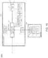
- Fig. 1 is a schematic diagram showing the structure of a projection system 1000 according to the first embodiment.
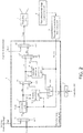
- Fig. 2 is a schematic diagram showing the structure of a projected image adjustment unit 1 of a projector apparatus 100 of the projection system 1000 according to the first embodiment.
- the projection system 1000 includes a projector apparatus 100 and a controller 200.
- the projected image adjustment unit 1 includes a first selector 11, a correction unit 12, a switcher 13, a rotation processing unit 14, a second selector 15, a keystone correction processing unit 16, a third selector 17, and a fourth selector 18.
- the first selector 11 receives an image Din (an image signal Din) inputted into the projector apparatus 100, a test image Img1 transmitted from the test image storage unit 2, and a selection signal sell. In accordance with the selection signal sell, the first selector 11 selects one of the image Din and the test image Img1, and then transmits the selected image (the selected image signal) as an image D1 (an image signal D1) to the correction unit 12.
- the selection signal sell is a control signal generated by a control unit (not shown) that controls each functional unit of the projector apparatus 100.
- the switcher 13 receives the signal Sig1 transmitted from the first interface 6 and a selection signal sel2. In accordance with the selection signal sel2, the switcher 13 transmits the signal Sig1 to the rotation processing unit 14 or the keystone correction processing unit 16.
- the selection signal sel2 is a control signal generated by a control unit that controls each functional unit of the projector apparatus 100.
- the rotation processing unit 14 receives the image D2 transmitted from the correction unit 12, the three-dimensional shape data 3D_data transmitted from the three-dimensional shape data storage unit 5, the information P_prj on the projection point of the projection unit 3, and the signal Sig1 transmitted from the switcher 13. When the signal Sig1 is inputted, the rotation processing unit 14 performs rotation processing on the image D2 based on the three-dimensional shape data 3D_data and the information P_prj on the projection point of the projection unit 3. The rotation processing unit 14 then transmits the processed image as an image D21 (an image signal D21) to the second selector 15.
- the second selector 15 receives the image D2 transmitted from the correction unit 12, the image D21 transmitted from the rotation processing unit 14, and a selection signal sel3. In accordance with the selection signal sel3, the second selector 15 selects one of the image D2 and the image D21, and transmits the selected image as an image D3 (an image signal D3) to the keystone correction processing unit 16 and the third selector 17.
- the selection signal sel3 is a control signal generated by a control unit that controls each functional unit of the projector apparatus 100.
- the keystone correction processing unit 16 receives the image D3 transmitted from the second selector 15, the three-dimensional shape data 3D_data transmitted from the three-dimensional shape data storage unit 5, the information P_prj on the projection point of the projection unit 3, and the signal Sig1 transmitted from the switcher 13. When the signal Sig1 is inputted, the keystone correction processing unit 16 performs keystone correction processing on the image D3 based on the three-dimensional shape data 3D_data and the information P_prj on the projection point of the projection unit 3. The keystone correction processing unit 16 then transmits the processed image as an image D31 (an image signal D31) to the third selector 17.
- the third selector 17 receives the image D3 transmitted from the second selector 15, the image D31 transmitted from the keystone correction processing unit 16, and the selection signal sel4.
- the third selector 17 selects one of the image D3 and the image D31 in accordance with the selection signal sel4 and transmits the selected image as an image D4 (an image signal D4) to the fourth selector 18.
- the selection signal sel4 is a control signal generated by a control unit that controls each functional unit of the projector apparatus 100.
- the fourth selector 18 receives the image D4 transmitted from the third selector 17, the test image lmg0 transmitted from the test image storage unit 2, and the selection signal sel5. In accordance with the selection signal sel5, the fourth selector 18 selects one of the image D4 and the test image Img0, and transmits the selected image as an image Dout (an image signal Dout) to the projection unit 3.
- the selection signal sel5 is a control signal generated by a control unit that controls each functional unit of the projector apparatus 100.
- the test image storage unit 2 stores a test image, and outputs a test image to the projected image adjustment unit 1 at a predetermined timing in accordance with a request from the projected image adjustment unit 1.
- the projection unit 3 includes an optical system for projecting an image.
- the projection unit 3 receives the image Dout (image signal Dout) transmitted from the fourth selector 18 of the projected image adjustment unit 1 and then projects the received image Dout (image signal Dout) onto the projection target in the three-dimensional space.
- the three-dimensional shape measurement unit 4 may obtain the three-dimensional measurement data of the projection target by obtaining a range image using the TOF (Time Of Flight) method (e.g., the TOF method using phase differences).
- the three-dimensional shape measurement unit 4 includes, for example, a light source for emitting infrared rays and an image sensor for infrared rays, and receives the reflected light of the infrared ray irradiated from the light source with the image sensor and measures a time period from when the infrared ray is irradiated to when the irradiated infrared ray is reflected at the projection target and returns to the light source, thereby obtaining a range image.
- the three-dimensional shape measurement unit 4 then obtains three-dimensional measurement data of the projection target from the obtained range image.
- the three-dimensional shape data storage unit 5 receives the three-dimensional measurement data of the projection target obtained by the three-dimensional shape measurement unit 4, and stores the received three-dimensional measurement data of the input projection target. In accordance with a request from the correction unit 12, the rotation processing unit 14, and/or the keystone correction processing unit 16, the three-dimensional shape data storage unit 5 transmits the three-dimensional measurement data to the correction unit 12, the rotation processing unit 14, and/or the keystone correction processing unit 16.
- the first interface 6 is an interface between the projector apparatus 100 and the controller 200. Via the first interface 6, a signal from the controller 200 can be transmitted to the projector apparatus 100.
- the second interface 21 is an interface between the controller 200 and the projector apparatus 100.
- the control unit 22 is a control unit that controls each functional unit of the controller 200.
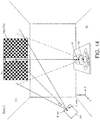
- Fig. 3 is a diagram schematically showing a three-dimensional space including a ceiling CL (horizontal ceiling CL) to be projected, the projector apparatus 100, and a user Usr on the floor FL.
- the ceiling CL (the horizontal ceiling CL) is a plane and is parallel to the floor FL which is a plane.
- the projection point of the projection unit 3 of the projector apparatus 100 is indicated as a point P_prj
- the measurement point of the three-dimensional shape measurement unit 4 of the projector apparatus 100 is indicated as a point P_msr.
- the intersection of the optical axis (projection axis) Ax1 of the optical system of the projection unit 3 and the horizontal ceiling CL (plane CL) is set as a point Pc, and the user's viewpoint position (the center point of both eyes of the user) is indicated as a point Vp.
- the intersection of a normal line Nm1, which passes through the point Pc, of the horizontal ceiling plane CL and a plane that is parallel to the floor plane FL and includes the point Vp is indicated as a point P1.
- the distance between the position of the left eye of the user Usr and the point Pc equals the distance between the position of the right eye of the user Usr and the point Pc.
- x-axis, the y-axis, and the z-axis are set as shown in Fig. 3 .
- the three-dimensional shape measurement unit 4 includes a camera, captures a test image for three-dimensional shape measurement projected from the projection unit 3, and obtains three-dimensional measurement data of the projection target based on the captured image of the test image for three-dimensional shape measurement.
- the test image lmg0 for three-dimensional shape measurement is transmitted from the test image storage unit 2 to the fourth selector 18 of the projected image adjustment unit 1.
- the control unit generates a selection signal sel5 for selecting the terminal 0 shown in Fig. 2 of the fourth selector 18, and transmits the selection signal to the fourth selector 18. This causes the test image lmg0 for three-dimensional shape measurement to be transmitted from the fourth selector 18 to the projection unit 3 as the image signal Dout.
- the projection unit 3 (A) sets the projection axis (the optical axis of the optical system of the projection unit 3) to the axis Ax1 shown in Fig. 3 , (B) sets the angle of view to an angel of ⁇ shown in Fig. 3 , (C) sets a projection point to the point P_prj shown in Fig. 3 , and then projects the test image lmg0 for three-dimensional shape measurement onto the horizontal ceiling CL, which is the projection target.
- the three-dimensional shape measurement unit 4 captures the test image Img0 for three-dimensional shape measurement projected by the projection unit 3 using a camera for three-dimensional shape measurement whose image capturing point is at the point P_msr.
- the three-dimensional shape measurement unit 4 compares the captured image with the test image lmg0 for three-dimensional shape measurement to obtain three-dimensional measurement data of the projection target.
- the coordinates, in the three-dimensional space, of the projection point P_prj are known
- the coordinates, in the three-dimensional space, of the imaging point P msr of the three-dimensional shape measurement unit 4 are known
- the test image lmg0 for three-dimensional shape measurement to be projected is also known; therefore, the coordinates, in the three-dimensional space, of the projection target can be calculated from the image captured at the image capturing point P_msr.
- examining which pixel in the captured test image Img0 for three-dimensional shape measurement corresponds to which pixel in the image captured at the image capturing point P msr allows for determining the position, in the three-dimensional space, corresponding to each pixel (the position, in the three-dimensional space, at which light corresponding to each pixel is reflected).
- specifying the three-dimensional spatial position corresponding to each pixel allows for calculating the coordinates, in the three-dimensional space, of the projection target.
- the three-dimensional shape data of the projection target obtained by the three-dimensional shape measurement unit 4 through the above processing is transmitted from the three-dimensional shape measurement unit 4 to the three-dimensional shape data storage unit 5 and then is stored in the three-dimensional shape data storage unit 5.
- the test image Img1 is transmitted from the test image storage unit 2 to the first selector 11.
- the control unit then generates the selection signal sell for selecting the terminal 0 shown in Fig. 2 of the first selector 11 and transmits it to the first selector 11. This causes the test image Img1 to be transmitted from the first selector 11 to the correction unit 12 as the image signal D1.
- Fig. 4 shows an example of the test image Img1.
- the test image1 is an image in which a first lattice pattern which is a square pattern of a white background and a second lattice pattern which is a square pattern of a black background are alternately arranged in the horizontal and vertical directions in the image.
- the test image Img1 has a center line L1v at the center of the image, a circular dot C1 at the center point of the image Img1, and a line L1h in the upper portion of the image Img1, which extends toward the horizontal direction (lateral direction).
- the portion where the intersection of the line L1v and the line L1h exists is the upper portion of the image.
- an image such as the test image Img1 shown in Fig. 4 , for which the user easily recognizes the upper side of the image is employed as the test image used for the projection system 1000.
- the test image Img1 shown in Fig. 4 is an example and may be another image that the user can easily recognize the upper side of the image.
- test image an image is employed in which a first lattice pattern which is a square pattern of a white background and a second lattice pattern which is a square pattern of a black background are alternately arranged, over the whole image area, in the horizontal and vertical directions in the image and a specific pattern indicating the upper portion of the image is superimposed at a predetermined position of the image.
- test image Img1 shown in Fig. 4 is used as the test image.
- the correction unit 12 reads the three-dimensional shape data 3D_data from the three-dimensional shape data storage unit 5 to obtain three-dimensional coordinates data of the horizontal ceiling plane CL, which is the projection target. The correction unit 12 then performs correction processing on the image D1 such that the image is in a state without distortion as viewed from the point PI, which is a point directly below the intersection Pc of the projection axis Ax1 and the ceiling plane CL. The correction unit 12 then transmits the image after the correction processing to the second selector 15 as the image D2.
- the control unit generates the selection signal sel3 for selecting the terminal 0 shown in Fig. 2 of the second selector 15, and transmits it to the second selector 15. This causes the image D2 to be transmitted from the second selector 15 to the third selector 17 as the image signal D3.
- the control unit generates the selection signal sel4 for selecting the terminal 0 shown in Fig. 2 of the third selector 17, and transmits it to the third selector 17. This causes the image D3 to be transmitted from the third selector 17 to the fourth selector 18 as the image signal D4.
- the control unit generates the selection signal sel5 for selecting the terminal 1 shown in Fig. 2 of the fourth selector 18, and transmits it to the fourth selector 18. This causes the image D4 to be transmitted from the fourth selector 18 to the projection unit 3 as the image signal D4.
- the projection unit 3 projects the image Dout from the fourth selector 18 onto the horizontal ceiling plane CL by the projection axis Ax1 shown in Fig. 3 .
- This state is referred to as "State 1".
- Fig. 5 is a view of the horizontal ceiling plane CL, the floor FL, the viewpoint Vp of the user Usr, the point Pc, which is the intersection of the optical axis (projection axis) of the optical system of the projection unit 3 and the horizontal ceiling (plane) CL, and the point PI, which is the intersection of the normal line Nm1, which passes through the point Pc, of the horizontal ceiling plane CL and a plane that is parallel to the floor plane FL and includes the point Vp, in State 1 as viewed from the x-axis positive direction toward the negative x-axis direction (a plan view in the y-z plane).
- L1 represents a plane that is parallel to the floor FL and includes the viewpoint Vp.
- the test image Img1 viewed from the viewpoint Vp in State 1 is shown as the image Img1(Vp). Further, in Fig. 3 , the test image Img1 as viewed from the point P1 (the point directly below the point Pc) is shown as the image Img1(P1).
- the image D31 generated by the keystone correction processing unit 16 in this way is projected onto the horizontal ceiling plane CL by the projection unit 3. This state is referred to as "State 3".
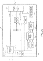
- the viewpoint identification processing unit 215 includes a viewpoint candidate obtaining unit 151 and a projection image obtaining unit 152.
- the inverse transformation matrix obtaining unit 1515 receives the data on the composite matrix R transmitted from the transformation matrix combining unit 1514.
- the inverse transformation matrix obtaining unit 1515 obtains an inverse transformation matrix R -1 from the composite matrix R and then transmits the data on the obtained inverse transformation matrix R -1 to the viewpoint candidate point calculation unit 1519.
- the transformation unit 1516 receives the data on the composite matrix R transmitted from the transformation matrix combining unit 1514 and the data Data(Pb) of the point Pb transmitted from the intersection calculation unit 1511.
- the transformation unit 1516 obtains data (coordinates data) on the point Pb', as Data (Pb'), from the composite matrix R and the data Data(Pb) of the point Pb.
- the transformation unit 1516 then transmits the obtained data Data(Pb') to the coefficient obtaining unit 1517 and the viewpoint candidate point calculation unit 1519.
- the projection image obtaining unit 152 Based on the three-dimensional shape data 3D_data and the information P_prj on the projection point of the projection unit 3, the projection image obtaining unit 152 converts the image D1 (test image Img1 (Img1_T3)) into an image without geometric distortion viewed from a viewpoint candidate point specified by the coordinates data Vp_cand, and then transmits the converted image, as an image D41 (image signal D41), to the fourth selector SEL4.
- the fourth selector SEL4 receives the image D4 transmitted from the third selector SEL3, the image D41 transmitted from the viewpoint identification processing unit 215, and the selection signal sel4.
- the fourth selector SEL4 selects one of the image D4 and the image D41 in accordance with the selection signal sel4, and transmits the selected image as an image D5 (image signal D5) to the fifth selector SEL5.
- the selection signal sel4 is a control signal generated by a control unit that controls each functional unit of the projector apparatus 2100.
- the projection unit 3 includes an optical system for projecting an image.
- the projection unit 3 receives the image Dout (image signal Dout) transmitted from the fifth selector SEL5 of the projected image adjustment unit 201 and then projects the received image Dout (image signal Dout) onto the projection target in the three-dimensional space.
- the three-dimensional shape measurement unit 4 obtains the three-dimensional measurement data of the projection target in the three-dimensional space and transmits the obtained three-dimensional measurement data of the projection target to the three-dimensional shape data storage unit 5.
- the three-dimensional shape measurement unit 4 has, for example, a camera, and captures the test image for three-dimensional shape measurement projected from the projection unit 3 to obtain the three-dimensional measurement data of the projection target based on the captured image of the test image for three-dimensional shape measurement.
- the three-dimensional shape measurement unit 4 may obtain the three-dimensional measurement data of the projection target by obtaining a range image using the TOF (Time Of Flight) method (e.g., the TOF method using phase differences).
- the three-dimensional shape measurement unit 4 includes, for example, a light source for emitting infrared rays and an image sensor for infrared rays, and receives the reflected light of the infrared ray irradiated from the light source with the image sensor and measures a time period from when the infrared ray is irradiated to when the irradiated infrared ray is reflected at the projection target and returns to the light source, thereby obtaining a range image.
- the three-dimensional shape measurement unit 4 then obtains three-dimensional measurement data of the projection target from the obtained range image.
- the three-dimensional shape data storage unit 5 receives the three-dimensional measurement data of the projection target obtained by the three-dimensional shape measurement unit 4, and stores the received three-dimensional measurement data of the input projection target. In accordance with a request from the correction unit 211, the first rotation processing unit 213, and/or viewpoint identification processing unit 215, the three-dimensional shape data storage unit 5 transmits the three-dimensional measurement data to the correction unit 211, the first rotation processing unit 213, and/or viewpoint identification processing unit 215.
- the first interface 6 is an interface between the projector apparatus 2100 and the controller 200. Via the first interface 6, a signal from the controller 200 can be transmitted to the projector apparatus 2100.
- the controller 200 includes a second interface 21, a control unit 22, and a user interface 23.
- the second interface 21 is an interface between the controller 200 and the projector apparatus 2100.
- Fig. 21 is a diagram schematically showing a three-dimensional space including a ceiling CL (included ceiling CL) to be projected, the projector apparatus 2100, and a user Usr on the floor FL. Further, a-axis, b-axis and c-axis are set as shown in Fig. 21 .
- the inclined ceiling CL is a flat surface and is inclined by the angle ⁇ shown in Fig. 21 with respect to the floor FL (the floor plane FL) which is a flat surface.
- the projection point of the projection unit 3 of the projector apparatus 2100 is indicated as a point P_prj
- the measurement point of the three-dimensional shape measurement unit 4 of the projector apparatus 2100 is indicated as a point P_msr.
- the three-dimensional shape measurement unit 4 includes a camera, captures a test image for three-dimensional shape measurement projected from the projection unit 3, and obtains three-dimensional measurement data of the projection target based on the captured image of the test image for three-dimensional shape measurement.
- examining which pixel in the captured test image Img0 for three-dimensional shape measurement corresponds to which pixel in the mage captured at the image capturing point P_msr allows for determining the position, in the three-dimensional space, corresponding to each pixel (the position, in the three-dimensional space, at which light corresponding to each pixel is reflected).
- specifying the three-dimensional spatial position corresponding to each pixel allows for calculating the coordinates, in the three-dimensional space, of the projection target.
- the three-dimensional shape data of the projection target obtained by the three-dimensional shape measurement unit 4 through the above processing is transmitted from the three-dimensional shape measurement unit 4 to the three-dimensional shape data storage unit 5 and then is stored in the three-dimensional shape data storage unit 5.
- Fig. 22 shows a first test image Img1_T1, which is an example of the test image Img1.
- the first test image Img1_T1 is a rectangular image.
- the first test image Img1_T1 is a pattern image that has a vertical center line L1v extending in the longitudinal direction (in the vertical direction) at the center in the lateral direction (the horizontal direction) of the image, and a horizontal line L2h extending in the lateral direction (in the horizontal direction) in the upper portion of the image.
- the portion where the intersection of the line L1v and the line L2h exists is the upper portion of the image.
- an image such as the first test image Img1_T1 shown in Fig. 22 , for which the user easily recognizes the upper side of the image is employed as the test image used for the projection system 2000.
- the first test image Img1_T1 shown in Fig. 22 is an example and may be another image for which the user can easily recognize the upper side of the image.
- the correction unit 211 reads the three-dimensional shape data 3D_data from the three-dimensional shape data storage unit 5 to obtain three-dimensional coordinates data of the inclined ceiling plane CL, which is the projection target. Using the obtained three-dimensional coordinate data of the inclined ceiling plane CL, the correction unit 211 then performs correction processing on the image D1 such that the image is in a state without distortion as viewed from the point PI, which is a point on the normal line of the ceiling plane CL that passes through the intersection Pc of the projection axis Ax1 and the ceiling plane CL. The correction unit 211 then transmits the image after the correction processing to the second selector SEL2 as the image D2.
- the control unit generates the selection signal sel2 for selecting the terminal 0 shown in Fig. 18 of the second selector SEL2, and transmits it to the second selector SEL2. This causes the image D2 to be transmitted from the second selector SEL2 to the third selector SEL3 as the image D3.
- the control unit generates the selection signal sel3 for selecting the terminal 0 shown in Fig. 18 of the third selector SEL3, and transmits it to the third selector SEL3. This causes the image D3 to be transmitted from the third selector SEL3 to the fourth selector SEL4 as the image D4.
- the control unit generates the selection signal sel4 for selecting the terminal 1 shown in Fig. 18 of the fourth selector SEL4, and transmits it to the fourth selector SEL4. This causes the image D4 to be transmitted from the fourth selector SEL4 to the fifth selector SEL5 as the image D5.
- the control unit generates a selection signal sel5 for selecting the terminal 1 shown in Fig. 18 of the fifth selector SEL5, and transmits it to the fifth selector SEL5. This causes the image D5 to be transmitted from the fifth selector SEL5 to the projection unit 3 as the image Dout.
- the projection unit 3 projects the image Dout from the fifth selector SEL5 onto the inclined ceiling plane CL by the projection axis Ax1 shown in Fig. 21 . This state is referred to as "State 1".
- Fig. 23 is a diagram schematically showing the three-dimensional space in State 1. More specifically, Fig. 23 is a diagram schematically showing a state in which the first test image Img1_T1 shown in Fig. 22 is projected on the inclined ceiling plane CL. In Fig. 23 , the first test image Img1_T1 viewed from the viewpoint Vp of the user in State 1 is shown as the image Img1_T1(Vp). In Fig. 23 , the first test image Img1_T1 viewed from the point P1 in State 1 is shown as the image Img1_T1(P1).
- the first rotation processing is performed.
- the user operates the controller 200 to rotate the image Img1_T1 projected on the inclined ceiling plane CL in the direction indicated by the arrow Dirl in Fig. 23 around the point Pc such that the vertical center line L1v of the image Img1_T1 appears to the user to be a straight vertical line as viewed from the user's viewpoint Vp. More specifically, the user operates the controller 200 to rotate the image Img1_T1 projected on the inclined ceiling plane CL in the direction indicated by the arrow Dirl in Fig. 23 around the point Pc such that a plane including the vertical center line L1v of the image Img1_T1, the point Pc, and the viewpoint Vp is orthogonal to a line connecting both eyes of the user.
- the user rotates the image Img1_T1 such that the upper portion of the image Img1_T1 (the portion where the line L1v intersects with the line L2h in the image Img1_T1) becomes the upper side as viewed from the user.
- test image Img1_T1 is transmitted from the test image storage unit 2 to the first selector SEL1.
- the control unit then generates a selection signal sell for selecting the terminal 0 shown in Fig. 18 of the first selector SEL1, and transmits it to the first selector SEL1.
- This causes the image Img1_T1 to be transmitted from the first selector SEL1 to the first switcher SW1 as the image signal D1.
- the control unit generates a switching signal sw1 for selecting the terminal 1 shown in Fig. 18 of the first switcher SW1, and transmits it to the first switcher SW1. This causes the image Img1_T1 to be transmitted from the first switcher SW1 to the correction unit 211 as the image signal D1.
- the correction unit 211 performs the same correction processing on the image D1 as the processing performed in State 1.
- the correction unit 211 then transmits the image after the correction processing to the first rotation processing unit 213 as the image D2.
- the user operates the controller 200 to cause the projector apparatus 2100 to perform the first rotation processing.
- the controller 200 has two buttons for performing the first rotation processing, and pressing the first button (one button) of the controller 200 once causes processing for rotating, by a predetermined angle, the test image Img1_T1 counterclockwise in the direction indicated by the direction Dirl in Fig. 23 to be performed, whereas pressing the second button (the other button) of the controller 200 once causes processing for rotating, by a predetermined angle, the test image Img1_T1 clockwise in the direction indicated by the direction Dirl in Fig. 23 to be performed.
- the user interface 23 When the first button of the controller 200 is pressed once, the user interface 23 generates a signal indicating that the first button has been pressed once. Based on the signal generated by the user interface 23, the control unit 22 of the controller 200 transmits a signal indicating that the first button has been pressed once to the first interface of the projector apparatus 2100 via the second interface 21.
- the user can operate the controller 200 in the user's hand, and the controller 200 transmits and/or receives signals to and/or from the projector apparatus 2100 by wireless communication.
- the user holds the controller 200 in hand and operates the controller 200, while viewing the image Img1_T1 projected on the inclined ceiling plane CL, to perform for rotating the image Img1_T1 projected on the inclined ceiling plane CL.
- the first interface of the projector apparatus 2100 receives the signal transmitted from the second interface of the controller 200 and transmits the received signal to the second switcher 212 as the signal Sig1.
- the second switcher 212 selects the terminal A shown in Fig. 18 in accordance with the switching signal sw2 generated by the control unit, and transmits the signal Sig1 to the first rotation processing unit 213.
- the first rotation processing unit 213 Based on the signal Sig1, the three-dimensional shape data 3D_data, and the information P_prj on the projection point of the projection unit 3, the first rotation processing unit 213 performs the first rotation processing on the image D2 transmitted from the correction unit 211.
- the first rotation processing unit 213 may perform the first rotation processing on the image D2 transmitted from the correction unit 211 based on the signal Sig1 without using the three-dimensional shape data 3D_data and the information P_prj on the projection point of the projection unit 3. In this case, the three-dimensional shape data 3D_data and the information P_prj on the projection point of the projection unit 3 may not be inputted into the first rotation processing unit 213.
- the first rotation processing unit 213 performs conversion processing (first rotation processing) on the image D2 such that the image Img1_T1 is rotated counterclockwise in the direction indicated by the arrow Dirl in Fig. 23 around the point Pc by an angle determined by the signal Sig1 as viewed from the point P1 to the inclined ceiling plane CL.
- the first rotation processing unit 213 then transmits the processed image as the image D21 (image signal D21) to the second selector SEL2.
- the second selector SEL2 selects the terminal 1 shown in Fig. 18 in accordance with the selection signal sel2 generated by the control unit, and transmits the image D21 as the image D3 to the third selector SEL3.
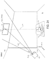
- Fig. 24 is a diagram schematically showing the three-dimensional space in State 2. As shown in Fig. 24 , in State 2, the test image Img1_T1 viewed from the viewpoint Vp of the user is shown as an image Img1_T1(Vp).
- the vertical center line L1v of the test image Img1_T1(Vp) appears to be a straight vertical line as viewed from the user's viewpoint Vp.
- the first rotation processing unit 213 obtains and holds the data for specifying a straight line including the vertical center line L1v.
- data for specifying a straight line including the vertical center line L1v include (1) data of an equation (a straight line equation) that defines the straight line and (2) data for specifying the coordinates of two different points included in the straight line.
- the first rotation processing unit 213 then transmits a detection signal including data for specifying a straight line including the vertical center line L1v as Det1 to the viewpoint identification processing unit 215.
- the projection system 2000 After performing the first rotation processing as described above, the projection system 2000 performs the second rotation processing.
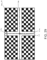
- Fig. 25 shows an example of a second test image Img1_T2, which is an example of the test image Img1 used for the second rotation processing.
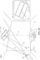
- Fig. 26 is a diagram describing the second rotation processing, and is a diagram (a front view) of the three-dimensional space including the inclined ceiling plane CL as viewed from the b-axis positive direction toward the b-axis negative direction.
- the correction unit 211 receives the second test image Img1_T2 as an input image, and then performs the correction processing on the received image in the same manner as described above. In other words, the following processing is performed.
- the control unit generates the selection signal sel2 for selecting the terminal 0 shown in Fig. 18 of the second selector SEL2, and transmits it to the second selector SEL2. This causes the image D2 to be transmitted from the second selector SEL2 to the third selector SEL3 as the image D3.
- the second rotation processing is performed.
- the second test image Img1_T2 is transmitted from the test image storage unit 2 to the first selector SEL1.
- the control unit then generates a selection signal sell for selecting the terminal 0 shown in Fig. 18 of the first selector SEL1, and transmits it to the first selector SEL1.
- This causes the second test image Img1_T2 to be transmitted from the first selector selector 1 to the first switcher SW1 as the image signal D1.
- the control unit generates a switching signal sw1 for selecting the terminal 1 shown in Fig. 18 of the first switcher SW1, and transmits it to the first switch SW1. This causes the second test image Img1_T2 to be transmitted from the first switcher SW1 to the correction unit 211 as the image signal D1.
- the correction unit 211 performs the same correction processing on the image D1 as the processing performed in State 3.
- the correction unit 211 then transmits the image after the correction processing to the second selector SEL2 as the image D2.
- the control unit generates the selection signal sel2 for selecting the terminal 0 shown in Fig. 18 of the second selector SEL2, and transmits it to the second selector SEL2. This causes the test image Img1_T2 to be transmitted from the second selector SEL2 to the second rotation processing unit 214 as the image signal D3.
- the user operates the controller 200 to cause the projector apparatus 2100 to perform the second rotation processing.
- the controller 200 has two buttons for performing the second rotation processing, and pressing the first button (one button) of the controller 200 once causes processing for rotating, by a predetermined angle, the second test image Img1_T2 counterclockwise in the direction indicated by the direction Dir2 in Fig. 26 to be performed, whereas pressing the second button (the other button) of the controller 200 once causes processing for rotating, by a predetermined angle, the test image Img1_T2 clockwise in the direction indicated by the direction Dir2 in Fig. 26 to be performed.
- the user can operate the controller 200 in the user's hand, and the controller 200 transmits and/or receives signals to and/or from the projector apparatus 2100 by wireless communication.
- the user holds the controller 200 in hand and operates the controller 200, while viewing the image Img1_T2 projected on the inclined ceiling plane CL, to rotate the image Img1_T2 projected onto the inclined ceiling plane CL.
- the first interface of the projector apparatus 2100 receives the signal transmitted from the second interface of the controller 200 and transmits the received signal to the second switcher 212 as the signal Sig1.
- the second switcher 212 selects the terminal B shown in Fig. 18 in accordance with the switching signal sw2 generated by the control unit, and transmits the signal Sig1 to the second rotation processing unit 214.
- the second rotation processing unit 214 performs the second rotation processing on the image D3 transmitted from the second selector SEL2 based on the signal Sig1, the three-dimensional shape data 3D_data, and the information P_prj on the projection point of the projection unit 3.
- the second rotation processing unit 214 may perform the second rotation processing on the image D3 transmitted from the correction unit 211 based on the signal Sig1 without using the three-dimensional shape data 3D_data and the information P_prj on the projection point of the projection unit 3. In this case, the three-dimensional shape data 3D_data and the information P_prj on the projection point of the projection unit 3 may not be inputted into the second rotation processing unit 214.
- the second rotation processing unit 214 performs conversion processing (second rotation processing) on the image D3 such that the image Img1_T2 is rotated counterclockwise in the direction indicated by the arrow Dir2 in Fig. 26 around the point Pc by an angle determined by the signal Sig1 as viewed from the point P1 to the inclined ceiling plane CL.
- the second rotation processing unit 214 then transmits the processed image as the image D31 (image signal D31) to the third selector SEL3.
- the third selector SEL3 selects the terminal 1 shown in Fig. 18 in accordance with the selection signal sel3 generated by the control unit, and transmits the image D31 as the image D4 to the fourth selector SEL4.
- the fourth selector SEL4 selects the terminal 1 shown in Fig. 18 in accordance with the selection signal sel4 generated by the control unit, and transmits the image D4 as the image D5 to the fifth selector SEL5.
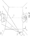
- Fig. 27 is a diagram schematically showing the three-dimensional space in State 4.
- the second rotation processing unit 214 obtains and holds the data for specifying a straight line including the horizontal center line L1h.
- data for specifying a straight line including the horizontal center line L1h include (1) data of an equation (a straight line equation) that defines the straight line and (2) data for specifying the coordinates of two different points included in the straight line.
- the second rotation processing unit 214 then transmits a detection signal including data for specifying a straight line including the horizontal center line L1h as Det2 to the viewpoint identification processing unit 215.
- the projection system 2000 After performing the second rotation processing as described above, the projection system 2000 performs the viewpoint identification processing.
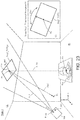
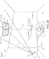
- Fig. 28 is a diagram describing the viewpoint identification processing. More specifically, Fig. 28 shows a test image Img1_T2 (Img1_T2(Vp)) projected on the inclined ceiling plane CL in State 4 with a test image Img1_T1 (Imp1_T2(Vp)) projected on the inclined ceiling plane CL in State 2 superimposed thereon.
- State 4A The state shown in Fig. 28 is referred to as "State 4A".
- Fig. 28 also shows a viewpoint candidate curve Vp_cand_crv indicating candidate points of the viewpoint.
- the intersection calculation unit 1511 of the viewpoint candidate obtaining unit 151 obtains first straight line data from the detection signal Det1 transmitted from the first rotation processing unit 213, and obtains the coordinates data Data(Pa) of the point Pa on the vertical center line L1v (the first line) in State 4A.
- the intersection calculation unit 1511 obtains second straight line data from the detection signal Det2 transmitted from the second rotation processing unit 214, and obtains the coordinates data Data(Pb) of the point Pb on the horizontal center line L1h (the second line) in State 4A.
- intersection calculation unit 1511 obtains the coordinates data of the points Pa, Pb, and Pc in the xyz space defined by the x-axis, the y-axis, and the z-axe shown in Fig. 21 as the following data.
- the intersection calculation unit 1511 transmits the obtained data Data(Pa) of the Pa and the obtained data Data(Pb) of the point Pb to the coefficient calculation unit 1512.
- the coefficient calculation unit 1512 transmits information (data) on the obtained coefficients A, B, and C to the transformation matrix obtaining unit 1513.
- the transformation matrix obtaining unit 1513 obtains transformation matrices Rx, Ry, and Rz by performing processing corresponding to the following formulae.
- Rx 1 A 2 + B 2 + C 2 A 2 + B 2 0 C 0 A 2 + B 2 + C 2 0 ⁇ C 0 A 2 + B 2
- the transformation matrix obtaining unit 1513 then transmits data on the obtained transformation matrices Rx, Ry, and Rz to the transformation matrix combining unit 1514.
- the inverse transformation matrix obtaining unit 1515 obtains an inverse transformation matrix R -1 from the composite matrix R and transmits the data on the obtained inverse transformation matrix R -1 to the viewpoint candidate point calculation unit 1519.
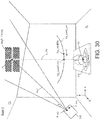
- the projection unit 3 projects the image Dout (image D41) onto the inclined ceiling CL.
- the user operates the controller 200 such that the degree of distortion of the third test image Img1_T3 projected on the inclined ceiling CL becomes small.
- an identified viewpoint candidate point after N-th (N is a natural number) viewpoint identification processing has been performed is indicated as Vp_cand(N); an identified viewpoint candidate point after N+1-th viewpoint identification processing has been performed is indicated as Vp_cand(N+1). It is assumed that the viewpoint candidate point Vp_cand(N+1) exists on a straight line connecting the point Pc and the user's viewpoint Vp.
- the viewpoint candidate point is set to Vp_cand(N+1); accordingly, the image without geometric distortion viewed from the user's viewpoint Vp is projected on the inclined ceiling CL.
- the viewpoint candidate point Vp_cand(N+1) exists on the straight line connecting the point Pc and the user's viewpoint Vp, and thus, in State 5, the third test image Img1_T3 appears to the user to be an image without geometric distortion as viewed from the user.
- the viewpoint identification processing is performed in the projection system 2000, thus allowing for projecting an image without geometric distortion (reduced geometric distortion) as viewed from the user's viewpoint Vp on the inclined ceiling plane CL.
- the user confirms the state (State 5) in which the geometric distortion of the image projected on the inclined ceiling plane CL is sufficiently reduced and then terminates the adjustment processing in the projector apparatus 2100 (the adjustment processing for reducing geometric distortion of the image).
- the user operates the controller 200 to terminate the adjustment processing (adjustment processing for reducing geometric distortion of the image) in the projector apparatus 2100.
- the projector apparatus 2100 receives a signal, from the controller 200, for terminating the adjustment processing (adjustment processing for reducing geometric distortion of the image) in the projector apparatus 2100.
- the projector apparatus 2100 When receiving the signal from the controller 200, the projector apparatus 2100 maintains a state in which an image is projected on the inclined ceiling using the current settings.
- the projector apparatus 2100 When the projector apparatus 2100 is switched to a mode for displaying (projecting) the image signal (or video signal) Din, the projector apparatus 2100 causes the first selector SEL1 to select the terminal 1, and causes the first switcher SW1 to select the terminal 0, thereby transmitting the image signal Din to the viewpoint identification processing unit 215.
- the viewpoint identification processing unit 215 then converts the image Din into an image without geometric distortion as viewed from the user's viewpoint Vp (the point Vp_cand(N+1)), and transmits the converted image to the fourth selector SEL4 as the image D41.
- the projection unit 3 of the projector apparatus 2100 projects the image Dout (image D41) onto the inclined ceiling CL.
- the projection system 2000 easily and appropriately eliminates (reduces) geometric distortion of an image projected on an inclined plane (e.g., an inclined ceiling) without using a device having a photographing function.
- an inclined plane e.g., an inclined ceiling
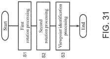
- step S1 the projection system 2000 performs first rotation processing.
- the first rotation processing is the same processing as one described in the above "2.2.3 First Rotation Processing".
- the user operates the controller 200 until the vertical center line L1v appears to be a vertical straight line in the first test image Img1_T1 projected on the inclined ceiling CL.
- step S2 the projection system 2000 performs the second rotation processing.
- the second rotation processing is the same processing as one described in the above "2.2.5 Second Rotation Processing".
- the user operates the controller 200 until the horizontal center line L1h appears to be a horizontal straight line in the second test image Img1_T2 projected on the inclined ceiling CL.
- step S3 the projection system 2000 performs viewpoint identification processing.
- the viewpoint identification processing is the same processing as one described in the above "2.2.6 Viewpoint Identification Processing".
- intersection calculation unit 1511 obtains the coordinates data of the points Pa, Pb, and Pc in the xyz space defined by the x-axis, the y-axis, and the z-axe shown in Fig. 21 as the following data.
- step S304 using the coefficients A, B, and C and the data Data(Pa) of the point Pa, the transformation matrix obtaining unit 1513 obtains transformation matrices Rx, Ry, and Rz by performing processing corresponding to the following formulae.
- Formula 15 Rx 1 A 2 + B 2 A 2 + B 2 0 0 0 A B 0 ⁇ B
- Formula 16 Ry 1 A 2 + B 2 + C 2 A 2 + B 2 0 C 0 A 2 + B 2 + C 2 0 ⁇ C 0 A 2 + B 2
- step S306 the inverse transformation matrix obtaining unit 1515 obtains an inverse transformation matrix R -1 from the composite matrix R.
- step S307 the transformation unit 1516 obtains data (coordinates data) on the point Pb' by performing processing corresponding to the following formula using the composite matrix R and the data Data(Pb) of the point Pb.
- Formula 18 b x ' b y ' b z ' R b x b y b z
- step S308 the angle obtaining unit 1518 receives the signal Sig1 transmitted from the first interface 6, and obtains the angle ⁇ based on the signal Sig1. For example, when receiving the signal Sig1, the angle obtaining unit 1518 varies the angle ⁇ by a predetermined angle from the angle set before receiving the signal Sig based on the signal value of the signal Sig1.
- step S310 based on the three-dimensional shape data 3D_data and the information P_prj on the projection point of the projection unit 3, the projection image obtaining unit 152 converts the received third test image Img1 (Img1_T3) into an image without geometric distortion viewed from a viewpoint candidate point identified by the coordinates data Vp_cand.
- step S311 the projection unit 3 projects the image (image Dout (image D41)) obtained in step S310 onto the inclined ceiling CL.
- step S312 the user determines whether the distortion of the third test image Img1_T3 projected on the inclined ceiling CL is not present (is sufficiently reduced).
- the process returns to step S301. Conversely, if it is determined that the distortion of the third test image Img1_T3 projected on the inclined ceiling CL is sufficiently reduced, the process is terminated (the viewpoint identification processing is terminated).
- the projection system 2000 projects a test image, in which the upper portion can be recognized when the image is displayed, onto the inclined ceiling plane CL, and the user operates the controller 200 to causes the projector apparatus 2100 to perform the following processes (1) to (3), thereby allowing for eliminating (reducing) geometric distortion in the image projected onto the inclined ceiling plane CL.
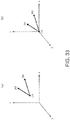
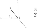
- Vec(m0, m1) a vector from a point m0 to a point m1 is referred to as Vec(m0, m1).
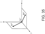
- Fig. 35 is a diagram showing points A0", B0", and C0" after performing the above processing.
- ⁇ is the rotation angle of the rotation processing around the x-axis and ⁇ is the rotation angle of the rotation processing around the y-axis.
- a vector from the point Pc to the point Pa in Fig. 28 (state 4A) is set to the above vector Vec(C0, A0) and the vector from the point Pc to the point Pb in Fig. 28 (state 4A) is set to the above vector Vec(C0, B0)
- a point (viewpoint candidate point Vp) from which a straight line (first straight line) passing through the points Pc and Pa in Fig. 28 (State 4A) appears to be orthogonal to a straight line (second straight line) passing through the points Pc and Pb can be calculated in the same manner as described above.
- the viewpoint identification processing is performed.
- the first interface, the second interface, and/or the third interface may be an interface for wireless communication or an interface for cable communication.
- the controller 200 has two buttons, which are the first button and the second button, and when the user operates the first button or the second button to perform the rotation processing or the keystone correction processing; however, the present invention should not be limited to this structure (this case).
- the controller 200 may have two buttons for the rotation processing, and may additionally have two buttons for the keystone correction processing.
- the controller 200 may have an interface other than buttons.
- the controller 200 may have a joystick, and the user operates the joystick to cause the projector apparatus 100 to perform the rotation processing or the keystone correction processing.
- test image used in the projection system should not be limited to the image shown in Fig. 4 ; any image for which a user can intuitively recognize a state for rotation of a projected image or a state for keystone correction for the projected image when the projection system 1000 projects an image in performing the rotation processing may be employed as the test image.
- test image used in the projection system should not be limited to a rectangular image; for example, it may be an image having another shape (other contour) such as an image having a circular shape or an image having an elliptical shape.
- the projection plane used in the projection system is described as a ceiling of a plane horizontal to the floor, but the present invention is not limited thereto; for example, the projection plane may be a plane obtained by rotating a plane horizontal to the floor around the axis that appears to the user to be a horizontal straight line as viewed from the user's viewpoint.
- a plane which is not inclined to either the left or the right and is inclined in the forward direction as viewed from the user may be used as the projection plane.
- a plane backward inclined plane which is not inclined to either the left side or the right side and is inclined in the backward direction as viewed from the user may be used as the projection plane.
- a plane parallel to a straight line connecting the left eye viewpoint and right eye viewpoint of the user may be used as the projection plane in the projection system of the present invention.
- the controller 200 has two buttons, which are the first button and the second button, and the user operates the first button or the second button to perform the first rotation processing, the second rotation processing, and/or the keystone correction processing is described; however the present invention should not be limited to this structure (this case).
- the controller 200 may have two buttons for the first rotation processing, two buttons for the second rotation processing, and two buttons for the viewpoint identification processing, separately.
- the controller 200 may have an interface other than buttons.
- the controller 200 may have a joystick, and the user operates the joystick to cause the projector apparatus 2100 to perform the first rotation processing, the second rotation processing, and/or the viewpoint identification processing.
- the projection plane of the projection system is a inclined ceiling plane as shown in Fig. 21 or the like; however the president invention should not be limited to this case.
- the projection plane may be a plane that is inclined in any direction by any angle with respect to the floor (or the viewpoint of the user). Even in such a case, performing the same processing as above allows an image to be projected on the projection plane, which is the inclined plane, without geometric distortion (with geometric distortion reduced) as viewed from the viewpoint of the user.
- LSI is used as the semiconductor device technology
- the technology may be an integrated circuit (IC), a system LSI, a super LSI, or an ultra LSI depending on the degree of integration of the circuit.
- the circuit integration technology employed should not be limited to LSI, but the circuit integration may be achieved using a dedicated circuit or a general-purpose processor.
- FPGA field programmable gate array
- reconfigurable processor which is an LSI circuit in which internal circuit cells are reconfigurable or more specifically the internal circuit cells can be reconnected or reset, may be used.
- All or part of the processes performed by the functional blocks described in the above embodiments may be implemented using programs. All or part of the processes performed by the functional blocks described in the above embodiments may be implemented by a central processing unit (CPU) in a computer.
- the programs for these processes may be stored in a storage device, such as a hard disk or a ROM, and may be executed from the ROM or be read into a RAM and then executed.
- the processes described in the above embodiments may be implemented by using either hardware or software (including use of an operating system (OS), middleware, or a predetermined library), or may be implemented using both software and hardware.
- OS operating system
- middleware middleware
- predetermined library a predetermined library
- the processing details for the correction processing, the first rotation processing, the second rotation processing, and the viewpoint identification processing are determined in the adjustment processing (the adjustment processing for reducing the geometric distortion of the image) in the above embodiments, the correction processing, the first rotation processing, the second rotation processing, and the viewpoint identification processing are not necessarily required to be performed separately; instead, an image process for performing a conversion process corresponding to all the processes for the correction processing, the first rotation processing, the second rotation processing, and the viewpoint identification processing may be performed in actually projecting an image.
- the present invention may also include a computer program enabling a computer to implement the method described in the above embodiments and a computer readable recording medium on which such a program is recorded.
- Examples of the computer readable recording medium include a flexible disk, a hard disk, a CD-ROM, an MO, a DVD, a DVD-ROM, a DVD-RAM, a large capacity DVD, a next-generation DVD, and a semiconductor memory .
- the computer program may not be recorded on the recording medium but may be transmitted with an electric communication line, a wireless or cable communication line, or a network such as the Internet.
- unit may include “circuitry,” which may be partly or entirely implemented by using either hardware or software, or both hardware and software.
Landscapes
- Engineering & Computer Science (AREA)
- Multimedia (AREA)
- Signal Processing (AREA)
- Physics & Mathematics (AREA)
- Geometry (AREA)
- General Physics & Mathematics (AREA)
- Theoretical Computer Science (AREA)
- Transforming Electric Information Into Light Information (AREA)
- Projection Apparatus (AREA)
Applications Claiming Priority (3)
| Application Number | Priority Date | Filing Date | Title |
|---|---|---|---|
| JP2015068987A JP6624799B2 (ja) | 2015-03-30 | 2015-03-30 | 投影システム、プロジェクター装置、および、プログラム |
| JP2016007581A JP6624942B2 (ja) | 2016-01-19 | 2016-01-19 | 投影システム、プロジェクター装置、および、プログラム |
| PCT/JP2016/056253 WO2016158166A1 (fr) | 2015-03-30 | 2016-03-01 | Système de projection, dispositif de projecteur, et programme |
Publications (3)
| Publication Number | Publication Date |
|---|---|
| EP3280136A1 true EP3280136A1 (fr) | 2018-02-07 |
| EP3280136A4 EP3280136A4 (fr) | 2018-08-29 |
| EP3280136B1 EP3280136B1 (fr) | 2021-04-28 |
Family
ID=57004521
Family Applications (1)
| Application Number | Title | Priority Date | Filing Date |
|---|---|---|---|
| EP16772050.7A Active EP3280136B1 (fr) | 2015-03-30 | 2016-03-01 | Systèmes de projection et procédés de projection |
Country Status (3)
| Country | Link |
|---|---|
| US (1) | US9928580B2 (fr) |
| EP (1) | EP3280136B1 (fr) |
| WO (1) | WO2016158166A1 (fr) |
Families Citing this family (7)
| Publication number | Priority date | Publication date | Assignee | Title |
|---|---|---|---|---|
| JP6636252B2 (ja) * | 2015-03-19 | 2020-01-29 | 株式会社メガチップス | 投影システム、プロジェクター装置、撮像装置、および、プログラム |
| CN105093789B (zh) * | 2015-07-03 | 2021-05-11 | 中兴通讯股份有限公司 | 一种实现投影面梯形失真校正的方法及装置和投影仪 |
| JP2017055178A (ja) * | 2015-09-07 | 2017-03-16 | ソニー株式会社 | 情報処理装置、情報処理方法、およびプログラム |
| JP6780315B2 (ja) * | 2016-06-22 | 2020-11-04 | カシオ計算機株式会社 | 投影装置、投影システム、投影方法及びプログラム |
| CN108303117B (zh) * | 2017-01-12 | 2020-06-02 | 中国农业大学 | 一种基于后方交会测量的云镜摄系统参数测量方法及系统 |
| US11184641B2 (en) * | 2017-05-09 | 2021-11-23 | Koninklijke Kpn N.V. | Coding spherical video data |
| CN113923428B (zh) * | 2021-11-23 | 2024-01-30 | 中国航空工业集团公司洛阳电光设备研究所 | 一种平显投影装置投影精度快速校准终端及校准方法 |
Family Cites Families (11)
| Publication number | Priority date | Publication date | Assignee | Title |
|---|---|---|---|---|
| CN100380944C (zh) * | 2002-10-08 | 2008-04-09 | 索尼株式会社 | 图像转换设备、图像转换方法和图像投影设备 |
| JP4283632B2 (ja) * | 2003-10-16 | 2009-06-24 | 日本電信電話株式会社 | 情報提示装置、情報提示システム、情報提示方法および情報提示プログラム |
| JP2006033357A (ja) | 2004-07-15 | 2006-02-02 | Olympus Corp | 画像変換装置及び映像投影装置 |
| JP4710780B2 (ja) * | 2006-09-28 | 2011-06-29 | 日本ビクター株式会社 | 画像投影表示装置 |
| US7857461B2 (en) | 2007-11-06 | 2010-12-28 | Panasonic Corporation | Projector and projection method |
| JP5121673B2 (ja) * | 2007-11-06 | 2013-01-16 | パナソニック株式会社 | 画像投影装置及び画像投影方法 |
| JP5783829B2 (ja) * | 2011-07-21 | 2015-09-24 | 三菱プレシジョン株式会社 | 映像の歪みを補正する方法、映像の歪みを補正する装置、模擬視界表示装置及び操縦訓練のためのシミュレータ |
| JP2014131257A (ja) * | 2012-11-27 | 2014-07-10 | Ricoh Co Ltd | 画像補正システム、画像補正方法及びプログラム |
| US20150319514A1 (en) | 2012-12-07 | 2015-11-05 | Roger N. Hitchcock | Electroactive polymer actuated aperture |
| JP6172495B2 (ja) * | 2012-12-28 | 2017-08-02 | 株式会社リコー | 校正装置、装置、プロジェクタ、3次元スキャナ、校正方法、方法、プログラム、及び記憶媒体 |
| CN103974048B (zh) * | 2014-04-28 | 2016-05-04 | 京东方科技集团股份有限公司 | 控制可穿戴设备投影的方法及装置、可穿戴设备 |
-
2016
- 2016-03-01 WO PCT/JP2016/056253 patent/WO2016158166A1/fr not_active Ceased
- 2016-03-01 EP EP16772050.7A patent/EP3280136B1/fr active Active
-
2017
- 2017-09-28 US US15/719,329 patent/US9928580B2/en active Active
Also Published As
| Publication number | Publication date |
|---|---|
| EP3280136A4 (fr) | 2018-08-29 |
| US9928580B2 (en) | 2018-03-27 |
| WO2016158166A1 (fr) | 2016-10-06 |
| EP3280136B1 (fr) | 2021-04-28 |
| US20180018761A1 (en) | 2018-01-18 |
Similar Documents
| Publication | Publication Date | Title |
|---|---|---|
| EP3280136A1 (fr) | Système de projection, dispositif de projecteur, et programme | |
| JP6882868B2 (ja) | 画像処理装置、画像処理方法、システム | |
| JP5035372B2 (ja) | 三次元モデリング装置、三次元モデリング方法、ならびに、プログラム | |
| US20110235897A1 (en) | Device and process for three-dimensional localization and pose estimation using stereo image, and computer-readable storage medium storing the program thereof | |
| EP2854099B1 (fr) | Dispositif de traitement d'informations et procédé de traitement d'informations | |
| JP4481280B2 (ja) | 画像処理装置、及び画像処理方法 | |
| JP5248806B2 (ja) | 情報処理装置、情報処理方法 | |
| US10284831B2 (en) | Projection system, projector apparatus, image capturing apparatus, and projection method | |
| US11477432B2 (en) | Information processing apparatus, information processing method and storage medium | |
| CN112399158A (zh) | 投影图像校准方法、装置及投影设备 | |
| JP2007129709A (ja) | イメージングデバイスをキャリブレートするための方法、イメージングデバイスの配列を含むイメージングシステムをキャリブレートするための方法およびイメージングシステム | |
| JP3770280B2 (ja) | 三次元画像の表示方法及び装置 | |
| US11100699B2 (en) | Measurement method, measurement device, and recording medium | |
| US11055865B2 (en) | Image acquisition device and method of operating image acquisition device | |
| US20200358992A1 (en) | Image processing apparatus, display system, image processing method, and medium | |
| JP2004235934A (ja) | キャリブレーション処理装置、およびキャリブレーション処理方法、並びにコンピュータ・プログラム | |
| US10726569B2 (en) | Information processing apparatus, information processing method, and non-transitory computer-readable storage medium | |
| CN105335748A (zh) | 图像特征提取方法和系统 | |
| JP2017191492A (ja) | 情報処理装置、情報処理方法および映像生成システム | |
| JP2012048393A (ja) | 情報処理装置およびその動作方法 | |
| EP4350280A1 (fr) | Dispositif de mesure tridimensionnelle | |
| US11928775B2 (en) | Apparatus, system, method, and non-transitory medium which map two images onto a three-dimensional object to generate a virtual image | |
| JP2017092756A (ja) | 画像処理装置、画像処理方法、画像投影システムおよびプログラム | |
| JP6624942B2 (ja) | 投影システム、プロジェクター装置、および、プログラム | |
| JP6624799B2 (ja) | 投影システム、プロジェクター装置、および、プログラム |
Legal Events
| Date | Code | Title | Description |
|---|---|---|---|
| STAA | Information on the status of an ep patent application or granted ep patent |
Free format text: STATUS: THE INTERNATIONAL PUBLICATION HAS BEEN MADE |
|
| PUAI | Public reference made under article 153(3) epc to a published international application that has entered the european phase |
Free format text: ORIGINAL CODE: 0009012 |
|
| STAA | Information on the status of an ep patent application or granted ep patent |
Free format text: STATUS: REQUEST FOR EXAMINATION WAS MADE |
|
| 17P | Request for examination filed |
Effective date: 20170928 |
|
| AK | Designated contracting states |
Kind code of ref document: A1 Designated state(s): AL AT BE BG CH CY CZ DE DK EE ES FI FR GB GR HR HU IE IS IT LI LT LU LV MC MK MT NL NO PL PT RO RS SE SI SK SM TR |
|
| AX | Request for extension of the european patent |
Extension state: BA ME |
|
| DAV | Request for validation of the european patent (deleted) | ||
| DAX | Request for extension of the european patent (deleted) | ||
| STAA | Information on the status of an ep patent application or granted ep patent |
Free format text: STATUS: EXAMINATION IS IN PROGRESS |
|
| A4 | Supplementary search report drawn up and despatched |
Effective date: 20180726 |
|
| RIC1 | Information provided on ipc code assigned before grant |
Ipc: H04N 9/31 20060101ALI20180720BHEP Ipc: G09G 5/00 20060101ALI20180720BHEP Ipc: H04N 5/74 20060101AFI20180720BHEP Ipc: G09G 5/36 20060101ALI20180720BHEP Ipc: G03B 21/14 20060101ALI20180720BHEP |
|
| 17Q | First examination report despatched |
Effective date: 20180808 |
|
| REG | Reference to a national code |
Ref country code: DE Ref legal event code: R079 Ref document number: 602016056959 Country of ref document: DE Free format text: PREVIOUS MAIN CLASS: H04N0005740000 Ipc: H04N0009310000 |
|
| RIC1 | Information provided on ipc code assigned before grant |
Ipc: H04N 9/31 20060101AFI20201008BHEP |
|
| GRAP | Despatch of communication of intention to grant a patent |
Free format text: ORIGINAL CODE: EPIDOSNIGR1 |
|
| STAA | Information on the status of an ep patent application or granted ep patent |
Free format text: STATUS: GRANT OF PATENT IS INTENDED |
|
| INTG | Intention to grant announced |
Effective date: 20201120 |
|
| RIN1 | Information on inventor provided before grant (corrected) |
Inventor name: SHINGU, FUMIYA Inventor name: HOSOI, KAZUHIRO Inventor name: KAWAI, EIZI Inventor name: HARAGUCHI, YUKI Inventor name: TANAKA, MOTOYASU |
|
| GRAS | Grant fee paid |
Free format text: ORIGINAL CODE: EPIDOSNIGR3 |
|
| GRAA | (expected) grant |
Free format text: ORIGINAL CODE: 0009210 |
|
| STAA | Information on the status of an ep patent application or granted ep patent |
Free format text: STATUS: THE PATENT HAS BEEN GRANTED |
|
| RAP3 | Party data changed (applicant data changed or rights of an application transferred) |
Owner name: MEGACHIPS CORPORATION Owner name: NINTENDO CO., LTD. |
|
| RIN1 | Information on inventor provided before grant (corrected) |
Inventor name: TANAKA, MOTOYASU Inventor name: HARAGUCHI, YUKI Inventor name: SHINGU, FUMIYA Inventor name: KAWAI, EIZI Inventor name: HOSOI, KAZUHIRO |
|
| AK | Designated contracting states |
Kind code of ref document: B1 Designated state(s): AL AT BE BG CH CY CZ DE DK EE ES FI FR GB GR HR HU IE IS IT LI LT LU LV MC MK MT NL NO PL PT RO RS SE SI SK SM TR |
|
| REG | Reference to a national code |
Ref country code: GB Ref legal event code: FG4D |
|
| REG | Reference to a national code |
Ref country code: CH Ref legal event code: EP |
|
| REG | Reference to a national code |
Ref country code: AT Ref legal event code: REF Ref document number: 1388463 Country of ref document: AT Kind code of ref document: T Effective date: 20210515 |
|
| REG | Reference to a national code |
Ref country code: DE Ref legal event code: R096 Ref document number: 602016056959 Country of ref document: DE |
|
| REG | Reference to a national code |
Ref country code: IE Ref legal event code: FG4D |
|
| REG | Reference to a national code |
Ref country code: LT Ref legal event code: MG9D |
|
| REG | Reference to a national code |
Ref country code: AT Ref legal event code: MK05 Ref document number: 1388463 Country of ref document: AT Kind code of ref document: T Effective date: 20210428 |
|
| PG25 | Lapsed in a contracting state [announced via postgrant information from national office to epo] |
Ref country code: HR Free format text: LAPSE BECAUSE OF FAILURE TO SUBMIT A TRANSLATION OF THE DESCRIPTION OR TO PAY THE FEE WITHIN THE PRESCRIBED TIME-LIMIT Effective date: 20210428 Ref country code: AT Free format text: LAPSE BECAUSE OF FAILURE TO SUBMIT A TRANSLATION OF THE DESCRIPTION OR TO PAY THE FEE WITHIN THE PRESCRIBED TIME-LIMIT Effective date: 20210428 Ref country code: BG Free format text: LAPSE BECAUSE OF FAILURE TO SUBMIT A TRANSLATION OF THE DESCRIPTION OR TO PAY THE FEE WITHIN THE PRESCRIBED TIME-LIMIT Effective date: 20210728 Ref country code: FI Free format text: LAPSE BECAUSE OF FAILURE TO SUBMIT A TRANSLATION OF THE DESCRIPTION OR TO PAY THE FEE WITHIN THE PRESCRIBED TIME-LIMIT Effective date: 20210428 Ref country code: LT Free format text: LAPSE BECAUSE OF FAILURE TO SUBMIT A TRANSLATION OF THE DESCRIPTION OR TO PAY THE FEE WITHIN THE PRESCRIBED TIME-LIMIT Effective date: 20210428 Ref country code: NL Free format text: LAPSE BECAUSE OF FAILURE TO SUBMIT A TRANSLATION OF THE DESCRIPTION OR TO PAY THE FEE WITHIN THE PRESCRIBED TIME-LIMIT Effective date: 20210428 |
|
| PG25 | Lapsed in a contracting state [announced via postgrant information from national office to epo] |
Ref country code: RS Free format text: LAPSE BECAUSE OF FAILURE TO SUBMIT A TRANSLATION OF THE DESCRIPTION OR TO PAY THE FEE WITHIN THE PRESCRIBED TIME-LIMIT Effective date: 20210428 Ref country code: SE Free format text: LAPSE BECAUSE OF FAILURE TO SUBMIT A TRANSLATION OF THE DESCRIPTION OR TO PAY THE FEE WITHIN THE PRESCRIBED TIME-LIMIT Effective date: 20210428 Ref country code: PL Free format text: LAPSE BECAUSE OF FAILURE TO SUBMIT A TRANSLATION OF THE DESCRIPTION OR TO PAY THE FEE WITHIN THE PRESCRIBED TIME-LIMIT Effective date: 20210428 Ref country code: PT Free format text: LAPSE BECAUSE OF FAILURE TO SUBMIT A TRANSLATION OF THE DESCRIPTION OR TO PAY THE FEE WITHIN THE PRESCRIBED TIME-LIMIT Effective date: 20210830 Ref country code: NO Free format text: LAPSE BECAUSE OF FAILURE TO SUBMIT A TRANSLATION OF THE DESCRIPTION OR TO PAY THE FEE WITHIN THE PRESCRIBED TIME-LIMIT Effective date: 20210728 Ref country code: LV Free format text: LAPSE BECAUSE OF FAILURE TO SUBMIT A TRANSLATION OF THE DESCRIPTION OR TO PAY THE FEE WITHIN THE PRESCRIBED TIME-LIMIT Effective date: 20210428 Ref country code: GR Free format text: LAPSE BECAUSE OF FAILURE TO SUBMIT A TRANSLATION OF THE DESCRIPTION OR TO PAY THE FEE WITHIN THE PRESCRIBED TIME-LIMIT Effective date: 20210729 Ref country code: IS Free format text: LAPSE BECAUSE OF FAILURE TO SUBMIT A TRANSLATION OF THE DESCRIPTION OR TO PAY THE FEE WITHIN THE PRESCRIBED TIME-LIMIT Effective date: 20210828 |
|
| REG | Reference to a national code |
Ref country code: NL Ref legal event code: MP Effective date: 20210428 |
|
| PG25 | Lapsed in a contracting state [announced via postgrant information from national office to epo] |
Ref country code: DK Free format text: LAPSE BECAUSE OF FAILURE TO SUBMIT A TRANSLATION OF THE DESCRIPTION OR TO PAY THE FEE WITHIN THE PRESCRIBED TIME-LIMIT Effective date: 20210428 Ref country code: CZ Free format text: LAPSE BECAUSE OF FAILURE TO SUBMIT A TRANSLATION OF THE DESCRIPTION OR TO PAY THE FEE WITHIN THE PRESCRIBED TIME-LIMIT Effective date: 20210428 Ref country code: EE Free format text: LAPSE BECAUSE OF FAILURE TO SUBMIT A TRANSLATION OF THE DESCRIPTION OR TO PAY THE FEE WITHIN THE PRESCRIBED TIME-LIMIT Effective date: 20210428 Ref country code: SK Free format text: LAPSE BECAUSE OF FAILURE TO SUBMIT A TRANSLATION OF THE DESCRIPTION OR TO PAY THE FEE WITHIN THE PRESCRIBED TIME-LIMIT Effective date: 20210428 Ref country code: SM Free format text: LAPSE BECAUSE OF FAILURE TO SUBMIT A TRANSLATION OF THE DESCRIPTION OR TO PAY THE FEE WITHIN THE PRESCRIBED TIME-LIMIT Effective date: 20210428 Ref country code: RO Free format text: LAPSE BECAUSE OF FAILURE TO SUBMIT A TRANSLATION OF THE DESCRIPTION OR TO PAY THE FEE WITHIN THE PRESCRIBED TIME-LIMIT Effective date: 20210428 Ref country code: ES Free format text: LAPSE BECAUSE OF FAILURE TO SUBMIT A TRANSLATION OF THE DESCRIPTION OR TO PAY THE FEE WITHIN THE PRESCRIBED TIME-LIMIT Effective date: 20210428 |
|
| REG | Reference to a national code |
Ref country code: DE Ref legal event code: R097 Ref document number: 602016056959 Country of ref document: DE |
|
| PLBE | No opposition filed within time limit |
Free format text: ORIGINAL CODE: 0009261 |
|
| STAA | Information on the status of an ep patent application or granted ep patent |
Free format text: STATUS: NO OPPOSITION FILED WITHIN TIME LIMIT |
|
| 26N | No opposition filed |
Effective date: 20220131 |
|
| PG25 | Lapsed in a contracting state [announced via postgrant information from national office to epo] |
Ref country code: IS Free format text: LAPSE BECAUSE OF FAILURE TO SUBMIT A TRANSLATION OF THE DESCRIPTION OR TO PAY THE FEE WITHIN THE PRESCRIBED TIME-LIMIT Effective date: 20210828 Ref country code: AL Free format text: LAPSE BECAUSE OF FAILURE TO SUBMIT A TRANSLATION OF THE DESCRIPTION OR TO PAY THE FEE WITHIN THE PRESCRIBED TIME-LIMIT Effective date: 20210428 |
|
| PG25 | Lapsed in a contracting state [announced via postgrant information from national office to epo] |
Ref country code: IT Free format text: LAPSE BECAUSE OF FAILURE TO SUBMIT A TRANSLATION OF THE DESCRIPTION OR TO PAY THE FEE WITHIN THE PRESCRIBED TIME-LIMIT Effective date: 20210428 |
|
| PG25 | Lapsed in a contracting state [announced via postgrant information from national office to epo] |
Ref country code: MC Free format text: LAPSE BECAUSE OF FAILURE TO SUBMIT A TRANSLATION OF THE DESCRIPTION OR TO PAY THE FEE WITHIN THE PRESCRIBED TIME-LIMIT Effective date: 20210428 |
|
| REG | Reference to a national code |
Ref country code: CH Ref legal event code: PL |
|
| REG | Reference to a national code |
Ref country code: BE Ref legal event code: MM Effective date: 20220331 |
|
| PG25 | Lapsed in a contracting state [announced via postgrant information from national office to epo] |
Ref country code: LU Free format text: LAPSE BECAUSE OF NON-PAYMENT OF DUE FEES Effective date: 20220301 Ref country code: LI Free format text: LAPSE BECAUSE OF NON-PAYMENT OF DUE FEES Effective date: 20220331 Ref country code: IE Free format text: LAPSE BECAUSE OF NON-PAYMENT OF DUE FEES Effective date: 20220301 Ref country code: CH Free format text: LAPSE BECAUSE OF NON-PAYMENT OF DUE FEES Effective date: 20220331 |
|
| PG25 | Lapsed in a contracting state [announced via postgrant information from national office to epo] |
Ref country code: BE Free format text: LAPSE BECAUSE OF NON-PAYMENT OF DUE FEES Effective date: 20220331 |
|
| P01 | Opt-out of the competence of the unified patent court (upc) registered |
Effective date: 20230516 |
|
| PG25 | Lapsed in a contracting state [announced via postgrant information from national office to epo] |
Ref country code: HU Free format text: LAPSE BECAUSE OF FAILURE TO SUBMIT A TRANSLATION OF THE DESCRIPTION OR TO PAY THE FEE WITHIN THE PRESCRIBED TIME-LIMIT; INVALID AB INITIO Effective date: 20160301 |
|
| PG25 | Lapsed in a contracting state [announced via postgrant information from national office to epo] |
Ref country code: MK Free format text: LAPSE BECAUSE OF FAILURE TO SUBMIT A TRANSLATION OF THE DESCRIPTION OR TO PAY THE FEE WITHIN THE PRESCRIBED TIME-LIMIT Effective date: 20210428 Ref country code: CY Free format text: LAPSE BECAUSE OF FAILURE TO SUBMIT A TRANSLATION OF THE DESCRIPTION OR TO PAY THE FEE WITHIN THE PRESCRIBED TIME-LIMIT Effective date: 20210428 |
|
| PG25 | Lapsed in a contracting state [announced via postgrant information from national office to epo] |
Ref country code: TR Free format text: LAPSE BECAUSE OF FAILURE TO SUBMIT A TRANSLATION OF THE DESCRIPTION OR TO PAY THE FEE WITHIN THE PRESCRIBED TIME-LIMIT Effective date: 20210428 |
|
| PG25 | Lapsed in a contracting state [announced via postgrant information from national office to epo] |
Ref country code: MT Free format text: LAPSE BECAUSE OF FAILURE TO SUBMIT A TRANSLATION OF THE DESCRIPTION OR TO PAY THE FEE WITHIN THE PRESCRIBED TIME-LIMIT Effective date: 20210428 |
|
| PGFP | Annual fee paid to national office [announced via postgrant information from national office to epo] |
Ref country code: GB Payment date: 20260324 Year of fee payment: 11 |
|
| PGFP | Annual fee paid to national office [announced via postgrant information from national office to epo] |
Ref country code: DE Payment date: 20260319 Year of fee payment: 11 |
|
| PGFP | Annual fee paid to national office [announced via postgrant information from national office to epo] |
Ref country code: FR Payment date: 20260320 Year of fee payment: 11 |