EP3280228A1 - Système d'éclairage et procédé de commande d'un système d'éclairage - Google Patents
Système d'éclairage et procédé de commande d'un système d'éclairage Download PDFInfo
- Publication number
- EP3280228A1 EP3280228A1 EP17182080.6A EP17182080A EP3280228A1 EP 3280228 A1 EP3280228 A1 EP 3280228A1 EP 17182080 A EP17182080 A EP 17182080A EP 3280228 A1 EP3280228 A1 EP 3280228A1
- Authority
- EP
- European Patent Office
- Prior art keywords
- pwma
- lighting
- pwmn
- drive signals
- voltage source
- Prior art date
- Legal status (The legal status is an assumption and is not a legal conclusion. Google has not performed a legal analysis and makes no representation as to the accuracy of the status listed.)
- Granted
Links
Images




Classifications
-
- H—ELECTRICITY
- H05—ELECTRIC TECHNIQUES NOT OTHERWISE PROVIDED FOR
- H05B—ELECTRIC HEATING; ELECTRIC LIGHT SOURCES NOT OTHERWISE PROVIDED FOR; CIRCUIT ARRANGEMENTS FOR ELECTRIC LIGHT SOURCES, IN GENERAL
- H05B45/00—Circuit arrangements for operating light-emitting diodes [LED]
- H05B45/20—Controlling the colour of the light
- H05B45/24—Controlling the colour of the light using electrical feedback from LEDs or from LED modules
-
- H—ELECTRICITY
- H05—ELECTRIC TECHNIQUES NOT OTHERWISE PROVIDED FOR
- H05B—ELECTRIC HEATING; ELECTRIC LIGHT SOURCES NOT OTHERWISE PROVIDED FOR; CIRCUIT ARRANGEMENTS FOR ELECTRIC LIGHT SOURCES, IN GENERAL
- H05B45/00—Circuit arrangements for operating light-emitting diodes [LED]
- H05B45/10—Controlling the intensity of the light
-
- H—ELECTRICITY
- H05—ELECTRIC TECHNIQUES NOT OTHERWISE PROVIDED FOR
- H05B—ELECTRIC HEATING; ELECTRIC LIGHT SOURCES NOT OTHERWISE PROVIDED FOR; CIRCUIT ARRANGEMENTS FOR ELECTRIC LIGHT SOURCES, IN GENERAL
- H05B45/00—Circuit arrangements for operating light-emitting diodes [LED]
- H05B45/10—Controlling the intensity of the light
- H05B45/14—Controlling the intensity of the light using electrical feedback from LEDs or from LED modules
-
- H—ELECTRICITY
- H05—ELECTRIC TECHNIQUES NOT OTHERWISE PROVIDED FOR
- H05B—ELECTRIC HEATING; ELECTRIC LIGHT SOURCES NOT OTHERWISE PROVIDED FOR; CIRCUIT ARRANGEMENTS FOR ELECTRIC LIGHT SOURCES, IN GENERAL
- H05B45/00—Circuit arrangements for operating light-emitting diodes [LED]
- H05B45/30—Driver circuits
- H05B45/32—Pulse-control circuits
- H05B45/325—Pulse-width modulation [PWM]
-
- H—ELECTRICITY
- H05—ELECTRIC TECHNIQUES NOT OTHERWISE PROVIDED FOR
- H05B—ELECTRIC HEATING; ELECTRIC LIGHT SOURCES NOT OTHERWISE PROVIDED FOR; CIRCUIT ARRANGEMENTS FOR ELECTRIC LIGHT SOURCES, IN GENERAL
- H05B45/00—Circuit arrangements for operating light-emitting diodes [LED]
- H05B45/30—Driver circuits
- H05B45/345—Current stabilisation; Maintaining constant current
-
- H—ELECTRICITY
- H05—ELECTRIC TECHNIQUES NOT OTHERWISE PROVIDED FOR
- H05B—ELECTRIC HEATING; ELECTRIC LIGHT SOURCES NOT OTHERWISE PROVIDED FOR; CIRCUIT ARRANGEMENTS FOR ELECTRIC LIGHT SOURCES, IN GENERAL
- H05B45/00—Circuit arrangements for operating light-emitting diodes [LED]
- H05B45/30—Driver circuits
- H05B45/37—Converter circuits
- H05B45/3725—Switched mode power supply [SMPS]
-
- H—ELECTRICITY
- H05—ELECTRIC TECHNIQUES NOT OTHERWISE PROVIDED FOR
- H05B—ELECTRIC HEATING; ELECTRIC LIGHT SOURCES NOT OTHERWISE PROVIDED FOR; CIRCUIT ARRANGEMENTS FOR ELECTRIC LIGHT SOURCES, IN GENERAL
- H05B45/00—Circuit arrangements for operating light-emitting diodes [LED]
- H05B45/40—Details of LED load circuits
- H05B45/44—Details of LED load circuits with an active control inside an LED matrix
- H05B45/46—Details of LED load circuits with an active control inside an LED matrix having LEDs disposed in parallel lines
Definitions
- the description relates to lighting systems.
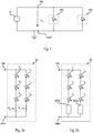
- FIG. 1 shows a typical lighting system.
- the lighting system includes a voltage source / voltage generator 12, configured to generate a constant direct voltage V out , such as e.g. 12 VCC or 24 VCC, between a positive terminal 106 and a ground terminal GND. Therefore, the voltage source 12 may be a battery or an electronic converter (e.g. a switching supply AC/DC or DC/DC), e.g. supplied by the mains.
- a voltage source / voltage generator 12 configured to generate a constant direct voltage V out , such as e.g. 12 VCC or 24 VCC, between a positive terminal 106 and a ground terminal GND. Therefore, the voltage source 12 may be a battery or an electronic converter (e.g. a switching supply AC/DC or DC/DC), e.g. supplied by the mains.
- a switching supply AC/DC or DC/DC e.g. supplied by the mains.
- a plurality of lighting modules 20a..20n are connected in parallel between line 106 and ground GND. Therefore, the lighting modules 20a..20n are all supplied with the voltage V out .
- Various embodiments of the present specification aim at providing a lighting system which is adapted to monitor the operation of the lighting modules connected to a voltage source.
- said object is achieved thanks to a lighting system having the features set forth in the claims that follow.
- the claims also concern a corresponding method of operating a lighting system.
- the present description relates to a lighting system.
- the system includes a voltage source adapted to generate a constant direct voltage, adapted to supply a plurality of lighting modules.
- the system includes a number n of electronic switches, wherein each electronic switch is configured to connect a respective lighting module to the voltage source as a function of a respective drive signal.
- the voltage source includes a positive terminal and a negative terminal, wherein each lighting module is connected on one side to the positive terminal and on the other side, through a respective electronic switch, to the negative terminal.
- the system includes a current sensor, such as a shunt resistor, connected in series with the voltage source, so as to detect a measurement signal indicative of the current supplied to the voltage source.
- a current sensor such as a shunt resistor
- the current sensor is connected between the negative terminal of the voltage source and the electronic switches.
- the system includes a control unit, designed to generate the drive signals.
- the drive signals are pulse-width-modulation signals having a given period and a given switch-on duration.
- the control unit determines the switch-on duration of each drive signal as a function of one or more control signals, e.g. in order to perform a colour correction and/or a dimming function.
- control unit varies, preferably only temporarily, the drive signals so that:
- control unit may vary the drive signals during the sequence of instants, so that every drive signal is high/low in a given instant, while all other drive signals are low/high in the same given instant.
- the period is the same for all drive signals.
- the control unit may vary the drive signals by delaying one or more drive signals, and/or by modifying the switch-on duration of one or more said drive signals.
- control unit estimates the current flowing through all lighting modules as a function of the measurement signal detected in the first instant, and estimates the currents flowing through the single lighting modules as a function of the measurement signals detected during the sequence of instants.
- control unit may determine a signal indicative of the (instantaneous) power absorbed as a function of the current flowing through all the lighting modules, and may determine one or more signals indicative of an error/failure as a function of the currents flowing through the single lighting modules.
- a lighting system may include a voltage source / voltage generator 12, configured to generate a constant direct voltage V out , such as for instance 12 VCC or 24 VCC, between a positive terminal 106 and a ground terminal GND. Therefore, the voltage source 12 may be a battery or an electronic converter (e.g. a switching supply AC/DC or DC/DC), for example supplied by the mains.
- a voltage source / voltage generator 12 configured to generate a constant direct voltage V out , such as for instance 12 VCC or 24 VCC, between a positive terminal 106 and a ground terminal GND.
- the voltage source 12 may be a battery or an electronic converter (e.g. a switching supply AC/DC or DC/DC), for example supplied by the mains.
- a plurality of lighting modules 20a..20n are connected in parallel between line 106 and ground GND. As a consequence, in the presently considered embodiment, the lighting modules 20a..20n are all supplied with voltage V out .
- each lighting module 20 includes one or more lighting sources.
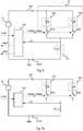
- Figure 2 shows a lighting module 20 including at least one LED (Light Emitting Diode) L, or other solid-state lighting means.
- lighting module 20 includes a LED chain, i.e. a plurality of LEDs connected in series between line 106 and ground GND.
- Figure 2 shows three LEDs L 1 , L 2 and L 3 .
- a LED (or a LED chain) is not supposed to be supplied directly with a constant voltage; an additional member must be provided to regulate or at least limit the current flowing through LED(s) L.
- lighting module 20 includes a resistor R La which is connected in series with LEDs L 1 , L 2 and L 3 and which limits the current flowing through the LEDs L.
- lighting module 20 may also include a plurality of LED chains connected in parallel, as schematically shown in Figure 2a , wherein lighting module 20 includes a second LED chain connected in parallel with the first LED chain, i.e. between terminals 106 and GND.
- the second chain includes three LEDs L 4 , L 5 and L 6 with a respective current limiting resistor R Lb .
- Figure 2b shows an embodiment wherein resistors R La and R Lb shown in Figure 2a have been replaced with current regulators or limiters 202a and 202b connected in series with the respective LED chain. Therefore, in the presently considered embodiment, one or more LED chains are again connected between terminals 106 and GND, and a current limiter is connected in series with each LED chain. For example, as known in the art, such a current limiter may be implemented e.g. with two bipolar transistors.
- FIG. 2c shows an embodiment wherein lighting module 20 includes an electronic converter 204, such as e.g. a "buck”, “boost”, “buck-boost”, “flyback” converter, etc., designed to receive a constant voltage through terminals 106 and GND and to provide, through both output terminals, a regulated current.
- an electronic converter 204 such as e.g. a "buck”, “boost”, “buck-boost”, “flyback” converter, etc.
- the LED chain(s) is/are connected in parallel at the output of electronic converter 204, which therefore enables the achievement of a correct supply of the LEDs.
- further components may be envisaged to better regulate the current flowing through the LED chains, e.g. because the LED chains may also have different requirements in supply voltage.
- the various lighting modules 20 shown in the Figures 2a to 2c may be combined within one and the same lighting system, e.g. by connecting different lighting modules 20 to the same voltage supply 12.
- each lighting module 20 is designed to be supplied with a constant voltage, and includes:
- FIG 3 shows an embodiment of a lighting system including a plurality of lighting modules 20a..20n.
- lighting modules 20a..20n may be integrated into one and the same physical module 20', for example they may be mounted onto the same printed circuit.
- the lighting system includes, for each lighting module 20a..20n, an electronic switch SWa..SWn, such as e.g. a Field-Effect Transistor (FET), for example a MOSFET (Metal-Oxide-Semiconductor Field-Effect Transistor) such as e.g. an n-type MOSFET.
- FET Field-Effect Transistor
- MOSFET Metal-Oxide-Semiconductor Field-Effect Transistor
- each electronic switch SWa..SWn is configured for selectively activating or deactivating a respective lighting module 20a..20n.
- each electronic switch SWa..SWn and the respective lighting module 20a..20n are connected in series between terminals 106 and GND. Therefore, if a plurality of modules 20a..20n are included into the same physical module 20', said physical module 20' may include a first terminal for the connection to line 106 and, for each lighting module 20a..20n, a respective terminal for the connection to a respective switch SWa..SWn.
- the electronic switches SWa..SWn are driven via respective drive signals PWMa..PWMn generated by a control unit 102 as a function of a control signal CRTL .
- each drive signal PWMa..PWMn corresponds to a Pulse-Width Modulation (PWM) signal.
- PWM Pulse-Width Modulation
- control unit 102 may change the duty cycle of one or more drive signals PWMa..PWMn in order to modify the brightness of certain lighting modules 20a..20n.
- control signal CTRL may be indicative of the requested colour.
- the lighting system comprises at least two lighting modules 20 emitting light with two different spectral characteristics, for example:
- Figure 5b shows an embodiment wherein the control unit 102 modifies the duty cycle of all drive signals PWMa..PWMn in order to regulate the brightness of the total light emitted simultaneously by all lighting modules 20a..20n, so-called dimming function.
- control signal CTRL may be indicative for the required total brightness.
- control unit 102 may vary the duty cycle of one or more, or even of all lighting modules, as a function of one or more control signals CTRL.
- the functions of colour correction and/or dimming are based on the on and off switching of the lighting modules for given periods, while the regulation of the current flowing through each lighting module 20 is performed irrespective of the module itself, and only during the period when the module is on.
- the switching frequency of the signals PWMa..PWMn should be higher than approximately 50 Hz, lest the human sight perceives flickerings or artifacts.
- the switching frequency of signals PWMa..PWMn should be typically lower than 5 kHz, e.g. in order not to interfere with an electronic converter within the lighting module.
- the switching frequency of signals PWMa..PWMn may range from 100 Hz and 5 kHz, preferably from 500 Hz to 2 kHz, for example 1 kHz.
- the drive signals PWMa..PWMn are synchronized so that the various lighting modules are on at the same time. For example, as shown in Figure 5a , if all pulses have the same duration T ON , the pulses take place at the same time. On the contrary, as shown in Figure 5b , if the pulses have different durations T ON , the pulses with shorter duration take place anyway in parallel with the longer pulses.
- this condition is guaranteed by the control unit 102, which synchronizes the instant of switching on lighting modules 20a..20n, e.g. by switching on all lighting modules 20a..20n simultaneously at the beginning of the PWM period, while the switch-on duration T ON may vary for the various lighting modules 20a..20n.
- the control unit 102 may synchronize the moment of switching off the lighting modules 20a..20n, i.e. it may switch off all lighting modules 20a..20n simultaneously.
- control unit 102 and the switches SWa..SWn enable a periodical on-off switching of lighting modules 20a..20n, while the current regulation for supplying the LEDs takes place independently within each lighting module 20a..20n.
- the lighting system is configured to measure in any case the current flowing through each lighting module 20a..20n.
- the measured current may be used to determine the energy consumption of the lighting modules 20a..20n and/or to detect a failure/disconnection of one or more lighting modules 20a..20n.
- a respective current sensor is used for each lighting module 20a..20n, such as for example a respective resistor connected in series with each lighting module 20a..20n.
- This embodiment has the drawback of requiring a plurality of current sensors and a corresponding number of measurement channels, e.g. a plurality of analog-to-digital converters.
- Figure 6 shows an embodiment of a lighting system including one single current sensor 104 for all the lighting modules 20a..20n.
- a current sensor 104 such as a resistor, a current sensor based on a current mirror etc. is interposed in the supply line 106 or preferably in the ground line GND, connecting the lighting modules 20a..20n to voltage source 12; in other words, the current sensor 104 is connected in series with voltage source 12.
- current sensor 104 is connected on one side (e.g. directly) to ground GND of voltage source 12, and is connected on the other side (e.g. directly) to each switch SWa..SWn.
- current sensor 104 is a shunt resistor R s , i.e. a resistor having a low resistance, e.g. between 10 mOhm and 100 Ohm.
- R s a shunt resistor
- the current flowing through resistor R s generates a voltage drop which may be measured e.g. via a line CS which is connected at the middle point between resistor R s and switches SWa..SWn. Therefore, the signal on this line CS, e.g. the voltage referred to ground GND, is indicative of the current flowing through current sensor 104 / resistor R s .
- line CS is also connected to control unit 102, which therefore is adapted to detect, e.g. via an analog-to-digital converter, the current flowing through current sensor 104 / resistor R s .
- the sensed current is indicative of the total current flowing through lighting modules 20a..20n, which are currently accessed via the respective switch SWa..SWn.
- control unit 102 is designed to make use of such total current in order to determine a PWR signal indicative of the instantaneous total electrical power absorbed by all lighting modules 20a..20n.
- control unit 102 may adjust, if necessary, the drive signals PWMa..PWMn described with reference to Figures 4, 5a and 5b , so that during one or more PWM cycles each lighting module 20a..20n is temporarily connected as one single lighting module 20a..20n in series with current sensor CS.
- control unit 102 determines, as previously described, the drive signals PWMa..PWMn as a function of one or more control signals CTRL, wherein said drive signals PWMa..PWMn represent required or reference signals. Subsequently, control unit 102 temporarily modifies, e.g. only during certain PWM cycles, said drive signals PWMa..PWMn so as to enable a current measurement of each lighting module 20a..20n.
- Figure 7a shows an embodiment of a lighting system wherein two lighting modules 20a and 20b may be connected to voltage source 12, and therefore there are provided two electronic switches SWa and SWb, and the control unit 102 is configured to generate two respective drive signals PWMa and PWMb.
- Figure 7b shows a first embodiment of drive signals PWMa and PWMb.
- signals PWMa and PWMb substantially correspond to the signals already shown in Figure 5a , wherein the drive signals have different durations, e.g. the drive signals PWMa and PWMb are switched on simultaneously, but they are switched off at different times.
- the switch-on time of drive signal PWMa is longer than the switch-on time of drive signal PWMb.
- control unit 102 may determine the total current flowing through both lighting modules, by measuring the signal on line CS while both signals PWMa and PWMb are high, e.g. in an instant t ab .
- control unit 102 may measure the instantaneous total current for each PWM cycle or periodically.
- control unit 102 may determine the current flowing only through module 20a, by measuring the signal on line CS, while signal PWMa is high and signal PWMb is low, e.g. at a time t b .
- control unit 102 may in any case determine the current flowing only through module 20b, by subtracting the current flowing only through module 20a from the total current.
- control unit performs, at least:
- the current of the last (i.e. of the n-th) lighting module may therefore be calculated from the other measurements, or a new measurement may be carried out.
- control unit 102 may verify whether the sum of the measures for the single lighting modules corresponds to the measure for all lighting modules, and optionally it may generate an error if data do not match.
- control unit 102 may also check if the current measured on line CS is equal to zero while all drive signals are low, e.g. at a time t off ⁇
- control unit may detect a possible failure of an electronic switch SW, and it may optionally generate an error signal ERR.
- control unit 102 may modify (optionally only temporarily) the drive signals PWMa and/or PWMb.
- Figure 7c shoes an embodiment wherein drive signals PWMa and PWMb have the same switch-on duration.
- control unit 102 is designed to delay one of the drive signals PWMa and PWMb.
- control unit 102 delays the drive signal PWMa during the second PWM cycle.
- the drive signal PWMa might even be delayed for all PWM cycles.
- This embodiment is therefore adapted to keep the ratio between T ON and T OFF , and therefore the brightness, constant. Indeed, as can be seen in Figure 7c , the absolute switch-on time T on remains constant within time period T pwm .
- Figure 7d shows a second embodiment, wherein the drive signals PWMa and PWMb have the same switch-on duration.
- control unit 102 is configured to temporarily modify the duration of one of the drive signals PWMa and PWMb (i.e. to lengthen or shorten the switch-on time). For example, in the presently considered embodiment, control unit 102 lengthens the duration of the drive signal PWMa during the second PWM cycle, and lengthens the duration of the drive signal PWMb during the third PWM cycle. Therefore, thanks to the modification of the switch-on time of the drive signals PWMa and PWMb, there are instants when:
- the switch-on time T ON is lengthened to carry out the measurement (instants t a and t b of Figure 7d ) thereby bringing about a change in the duty cycle and therefore in the brightness. In this case, at low dimming levels, the measurement may be visible.
- the lighting systems described in the foregoing are based on the use of PWM drive signals.
- these signals are normally used for colour correction and/or dimming. Therefore, situations may arise wherein one or more of the drive signals have a duty cycle of 100%.
- control unit 102 may modify (preferably only temporarily) the switch-on time, specifically by reducing the duty cycle.
- control unit 102 may reduce the duty cycle of the drive signal PWMb during a first PWM cycle, and reduce the duty cycle of the drive signal PWMa during a second PWM cycle. In this way, we find again instants when:
- the procedures of delaying / phase-shifting or modifying the PWM drive signals may be combined.
- the variation is only temporary, i.e. the control unit is designed to directly use the reference PWM drive signals that have been determined as a function of one or more control signals CTRL during the other PWM cycles.
- the procedures of delaying / phase-shifting or modifying the PWM drive signals may be applied to a higher number of lighting modules.
- Figure 8a shows an embodiment of a lighting system wherein three lighting modules 20a, 20b and 20c may be connected to the voltage source 12, and therefore there are provided three electronic switches SWa, SWb and SWc, and control unit 102 is configured to generate three respective drive signals PWMa, PWMb and PWMc.
- Figure 8b shows an embodiment wherein the drive signals PWMa, PWMb and PWMc have the same switch-on duration.
- control unit 102 is configured to delay, in certain PWM cycles, one of the drive signals PWMa, PWMb and PWMc.
- control unit 102 delays the drive signal PWMa during the first PWM cycle, delays the drive signal PWMb during the second PWM cycle and delays the drive signal PWMc during the first PWM cycle.
- Figure 8c shows an embodiment wherein control unit 102 is designed to temporarily modify, in given PWM cycles, the duration of one of the drive signals PWMa, PWMb and PWMc (specifically, to lengthen the switch-on time).
- control unit 102 lengthens the duration of drive signal PWMa during the first PWM cycle, lengthens the duration of drive signal PWMb during the second PWM cycle and lengthens the duration of drive signal PWMc during the second PWM cycle. Therefore, thanks to the modification of the switch-on time of drive signals PWMa, PWMb and PWMc there are again instants when:
- control unit 102 may combine both embodiments.
- Figure 8d shows an embodiment wherein drive signal PWMa has a duty cycle of 100% and the drive signals PWMb and PWMc have the same duty cycle, e.g. substantially of 50%.
- control unit 102 may be configured to temporarily modify, in given PWM cycles, the duration of drive signal PWMa (specifically, to shorten the switch-on time). Moreover, control unit 102 may temporarily delay, in given PWM cycles, one of the drive signals PWMb or PWMc, so as to ensure the presence of instants when:
- Figure 8e shows an embodiment which makes use of the drive signals PWMa, PWMb and PWMc shown in Figure 8b , but the instants of the current measurements are different. Specifically, thanks to phase shifting there are instants when:
- Figure 8f shows an embodiment substantially corresponding to Figure 8c , the difference consisting in a reduction of the switch-on times T ON ; in other words, there are instants when each time only one lighting module is off.
- control unit 102 is configured to modify the drive signals so that during a sequence of ( n -1) instants, each time a different set of lighting modules (20a..20n) is connected to the voltage source 12.
- control unit 102 may either switch on one different lighting module every time (direct current measurement) or switch off one different lighting module every time (current calculation from the difference).
- Figure 8g shows an embodiment wherein the current flowing through lighting module 20a is detected at time t a , when only signal PWMa is high.
- the current flowing through lighting module 20b is detected at time t b , when only signal PWMb is low.
- the current flowing through lighting module 20c may be calculated from the other measurements or may be detected at time t c , when only signal PWMc is low.
- control unit 102 takes advantage of the fact that the drive signals PWMa..PWMn are PWM signals.
- the lighting system includes a single current sensor, adapted to detect the instantaneous current provided by voltage source 12. Therefore, said single current sensor 104, such as e.g. a shunt resistor R s , enables the detection of the total current (i.e. the sum of the currents) of all lighting modules 20a..20c which are connected to voltage source 12.
- said single current sensor 104 such as e.g. a shunt resistor R s , enables the detection of the total current (i.e. the sum of the currents) of all lighting modules 20a..20c which are connected to voltage source 12.
- control unit 102 synchronizes the drive signals PWMa..PWMn, so as to ensure that in specific instants all drive signals PWMa..PWMn are high.
- the drive signals PWMa..PWMn are synchronized so that this condition is satisfied for every PWM cycle.
- control unit 102 sets all drive signals PWMa..PWMn simultaneously to high (synchronization of switching on) or to low (synchronization of switching off).
- this synchronization may optionally be valid only for the reference drive signals PWMa..PWMn, i.e. those signals normally used for the other PWM cycles.
- control unit 102 modifies (preferably only temporarily) the duty cycle of one or more drive signals PWMa.. PWMn and/or delays (preferably only temporarily) one or more drive signals PWMa..PWMn, so as to ensure that during a sequence of (n - 1) instants, every time a different set of lighting modules (20a..20n) is connected to voltage source 12.
- control unit 102 may vary the drive signals during the sequence of (n - 1) instants, so that each drive signal PWMa..PWMn is high/low at a given time, while all other drive signals PWMa..PWMn are low/high at the same time.
- the reference drive signals PWMa..PWMn are therefore substantially constant, and are determined as a function of a control signal CTRL, e.g. for a colour mixing and/or dimming function.
- the control unit adjusts (preferably only temporarily, i.e. during a sequence of some PWM cycles) the drive signals PWMa..PWMn in order to enable an individual measurement of the current flowing through each lighting module 20a..20c.
- control unit 102 may temporarily reduce the duty cycles, so that during a sequence of PWM cycles each drive signal PWMa..PWMn is high in a given instant, while all other drive signals PWMa..PWMn are low in that instant.
- control unit 102 is therefore adapted to detect the total current and the contribution of each single lighting module through one single measurement channel, e.g. through one single analog-to-digital converter. On the basis of these data, therefore, control unit 102 may calculate the absorbed power (PWR signal) and/or determine a failure or disconnection of a lighting module (signal ERR).
- the switches SAa..SWb are closed when the respective drive signal is high.
- the same principle may be applied also if the operation is inverted.
Landscapes
- Circuit Arrangement For Electric Light Sources In General (AREA)
Applications Claiming Priority (1)
| Application Number | Priority Date | Filing Date | Title |
|---|---|---|---|
| IT201600080749 | 2016-08-01 |
Publications (2)
| Publication Number | Publication Date |
|---|---|
| EP3280228A1 true EP3280228A1 (fr) | 2018-02-07 |
| EP3280228B1 EP3280228B1 (fr) | 2019-07-10 |
Family
ID=58545028
Family Applications (1)
| Application Number | Title | Priority Date | Filing Date |
|---|---|---|---|
| EP17182080.6A Active EP3280228B1 (fr) | 2016-08-01 | 2017-07-19 | Système d'éclairage et procédé de commande d'un système d'éclairage |
Country Status (2)
| Country | Link |
|---|---|
| US (1) | US9986608B2 (fr) |
| EP (1) | EP3280228B1 (fr) |
Cited By (2)
| Publication number | Priority date | Publication date | Assignee | Title |
|---|---|---|---|---|
| DE102017125173A1 (de) * | 2017-10-26 | 2019-05-02 | Preh Gmbh | Verfahren zur Funktionsüberprüfung mehrerer, pulsweitenmoduliert angesteuerter Lichtquellen |
| DE102019103660A1 (de) * | 2019-02-13 | 2020-08-13 | Vossloh-Schwabe Deutschland Gmbh | Betriebsschaltung für das Betreiben mehrerer Lasten |
Families Citing this family (6)
| Publication number | Priority date | Publication date | Assignee | Title |
|---|---|---|---|---|
| KR102581457B1 (ko) * | 2018-07-05 | 2023-09-21 | 엘지이노텍 주식회사 | 광원 구동장치 및 그 방법 |
| DE102019218941A1 (de) * | 2018-12-10 | 2020-06-10 | Koito Manufacturing Co., Ltd. | Lampenmodul |
| FR3102334B1 (fr) * | 2019-10-17 | 2022-04-29 | Psa Automobiles Sa | Procédé de pilotage des modules d’éclairage et de signalisation pour véhicules automobiles |
| US11497097B2 (en) | 2019-12-19 | 2022-11-08 | Magic Leap, Inc. | Control of dynamic brightness of light-emitting diode array |
| EP3920665B1 (fr) | 2020-06-03 | 2023-11-01 | Inventronics GmbH | Procédé de commande de sources lumineuses, et dispositif et système correspondants |
| KR102869102B1 (ko) * | 2020-10-13 | 2025-10-14 | 현대자동차주식회사 | 단일 채널 기반 다기능 led 램프 구동 시스템 및 방법 |
Citations (4)
| Publication number | Priority date | Publication date | Assignee | Title |
|---|---|---|---|---|
| WO2003032689A1 (fr) * | 2001-10-05 | 2003-04-17 | Koninklijke Philips Electronics N.V. | Commande pwm d'ensembles a led |
| DE102006005521B3 (de) * | 2006-02-07 | 2007-05-16 | Lear Corp | Schaltung und Verfahren zum Ansteuern eines LED-Array's |
| WO2009116854A2 (fr) * | 2008-03-17 | 2009-09-24 | Eldolab Holding B.V. | Ensemble à del, accessoire à del, procédé de commande et programme logiciel |
| EP3013122A2 (fr) * | 2014-09-22 | 2016-04-27 | Zizala Lichtsysteme GmbH | Procede et agencement de circuit destine a alimenter un circuit en serie de n unites a del |
Family Cites Families (1)
| Publication number | Priority date | Publication date | Assignee | Title |
|---|---|---|---|---|
| WO2013090945A1 (fr) * | 2011-12-16 | 2013-06-20 | Advanced Lighting Technologies, Inc. | Procédé et système de modernisation par lampes à diodes électroluminescentes, à longue durée de vie, bon marché, et à facteur de puissance proche de l'unité |
-
2017
- 2017-07-19 EP EP17182080.6A patent/EP3280228B1/fr active Active
- 2017-07-26 US US15/659,666 patent/US9986608B2/en active Active
Patent Citations (4)
| Publication number | Priority date | Publication date | Assignee | Title |
|---|---|---|---|---|
| WO2003032689A1 (fr) * | 2001-10-05 | 2003-04-17 | Koninklijke Philips Electronics N.V. | Commande pwm d'ensembles a led |
| DE102006005521B3 (de) * | 2006-02-07 | 2007-05-16 | Lear Corp | Schaltung und Verfahren zum Ansteuern eines LED-Array's |
| WO2009116854A2 (fr) * | 2008-03-17 | 2009-09-24 | Eldolab Holding B.V. | Ensemble à del, accessoire à del, procédé de commande et programme logiciel |
| EP3013122A2 (fr) * | 2014-09-22 | 2016-04-27 | Zizala Lichtsysteme GmbH | Procede et agencement de circuit destine a alimenter un circuit en serie de n unites a del |
Cited By (4)
| Publication number | Priority date | Publication date | Assignee | Title |
|---|---|---|---|---|
| DE102017125173A1 (de) * | 2017-10-26 | 2019-05-02 | Preh Gmbh | Verfahren zur Funktionsüberprüfung mehrerer, pulsweitenmoduliert angesteuerter Lichtquellen |
| DE102017125173B4 (de) | 2017-10-26 | 2022-09-08 | Preh Gmbh | Verfahren zur Funktionsüberprüfung mehrerer, pulsweitenmoduliert angesteuerter Lichtquellen |
| DE102019103660A1 (de) * | 2019-02-13 | 2020-08-13 | Vossloh-Schwabe Deutschland Gmbh | Betriebsschaltung für das Betreiben mehrerer Lasten |
| DE102019103660B4 (de) * | 2019-02-13 | 2025-09-11 | Vossloh-Schwabe Deutschland Gmbh | Betriebsschaltung für das Betreiben mehrerer Lasten |
Also Published As
| Publication number | Publication date |
|---|---|
| EP3280228B1 (fr) | 2019-07-10 |
| US9986608B2 (en) | 2018-05-29 |
| US20180035502A1 (en) | 2018-02-01 |
Similar Documents
| Publication | Publication Date | Title |
|---|---|---|
| EP3280228B1 (fr) | Système d'éclairage et procédé de commande d'un système d'éclairage | |
| US10757784B2 (en) | Control apparatus and lighting apparatus with first and second voltage converters | |
| EP2592903B1 (fr) | Sytsteme d'èclairage et luminaire | |
| US8638045B2 (en) | Mutli-string LED current control system and method | |
| US9374083B2 (en) | Switching current control circuit, LED dimmer system, and LED illumination device | |
| EP3348121B1 (fr) | Circuit et procédé de commande d'éclairage pour del multiples | |
| JP5665382B2 (ja) | Led電源装置及びled照明器具 | |
| US9055646B2 (en) | Light emitting device driver circuit and control method thereof | |
| CN102598854B (zh) | 脉冲宽度调制的led的操作 | |
| WO2008001246A1 (fr) | Circuit d'attaque destiné à exciter une charge avec un courant constant | |
| US9167658B2 (en) | Light emitting element lighting device and lighting fixture using same | |
| US11246194B2 (en) | Driver circuit with a semiconductor light source and method for operating a driver circuit | |
| JP5538078B2 (ja) | Led電源装置 | |
| WO2013104684A1 (fr) | Contrôleur de lampe | |
| KR20150071708A (ko) | 롤링 블랙아웃 조정가능한 컬러 led 조명원 | |
| EP3451798B1 (fr) | Circuit d'alimentation électrique et système d'éclairage et procédé pour faire fonctionner un circuit d'alimentation électrique | |
| CA2783250C (fr) | Architecture d'eclairage a del comportant un convertisseur de tension | |
| US20250311074A1 (en) | Driving system for a lighting apparatus |
Legal Events
| Date | Code | Title | Description |
|---|---|---|---|
| PUAI | Public reference made under article 153(3) epc to a published international application that has entered the european phase |
Free format text: ORIGINAL CODE: 0009012 |
|
| STAA | Information on the status of an ep patent application or granted ep patent |
Free format text: STATUS: THE APPLICATION HAS BEEN PUBLISHED |
|
| AK | Designated contracting states |
Kind code of ref document: A1 Designated state(s): AL AT BE BG CH CY CZ DE DK EE ES FI FR GB GR HR HU IE IS IT LI LT LU LV MC MK MT NL NO PL PT RO RS SE SI SK SM TR |
|
| AX | Request for extension of the european patent |
Extension state: BA ME |
|
| STAA | Information on the status of an ep patent application or granted ep patent |
Free format text: STATUS: REQUEST FOR EXAMINATION WAS MADE |
|
| 17P | Request for examination filed |
Effective date: 20180731 |
|
| RBV | Designated contracting states (corrected) |
Designated state(s): AL AT BE BG CH CY CZ DE DK EE ES FI FR GB GR HR HU IE IS IT LI LT LU LV MC MK MT NL NO PL PT RO RS SE SI SK SM TR |
|
| GRAP | Despatch of communication of intention to grant a patent |
Free format text: ORIGINAL CODE: EPIDOSNIGR1 |
|
| STAA | Information on the status of an ep patent application or granted ep patent |
Free format text: STATUS: GRANT OF PATENT IS INTENDED |
|
| GRAJ | Information related to disapproval of communication of intention to grant by the applicant or resumption of examination proceedings by the epo deleted |
Free format text: ORIGINAL CODE: EPIDOSDIGR1 |
|
| STAA | Information on the status of an ep patent application or granted ep patent |
Free format text: STATUS: REQUEST FOR EXAMINATION WAS MADE |
|
| INTG | Intention to grant announced |
Effective date: 20181130 |
|
| INTC | Intention to grant announced (deleted) | ||
| GRAP | Despatch of communication of intention to grant a patent |
Free format text: ORIGINAL CODE: EPIDOSNIGR1 |
|
| STAA | Information on the status of an ep patent application or granted ep patent |
Free format text: STATUS: GRANT OF PATENT IS INTENDED |
|
| INTG | Intention to grant announced |
Effective date: 20190215 |
|
| GRAS | Grant fee paid |
Free format text: ORIGINAL CODE: EPIDOSNIGR3 |
|
| GRAA | (expected) grant |
Free format text: ORIGINAL CODE: 0009210 |
|
| STAA | Information on the status of an ep patent application or granted ep patent |
Free format text: STATUS: THE PATENT HAS BEEN GRANTED |
|
| AK | Designated contracting states |
Kind code of ref document: B1 Designated state(s): AL AT BE BG CH CY CZ DE DK EE ES FI FR GB GR HR HU IE IS IT LI LT LU LV MC MK MT NL NO PL PT RO RS SE SI SK SM TR |
|
| REG | Reference to a national code |
Ref country code: GB Ref legal event code: FG4D |
|
| REG | Reference to a national code |
Ref country code: CH Ref legal event code: EP Ref country code: AT Ref legal event code: REF Ref document number: 1154938 Country of ref document: AT Kind code of ref document: T Effective date: 20190715 |
|
| REG | Reference to a national code |
Ref country code: IE Ref legal event code: FG4D |
|
| REG | Reference to a national code |
Ref country code: DE Ref legal event code: R096 Ref document number: 602017005148 Country of ref document: DE |
|
| REG | Reference to a national code |
Ref country code: NL Ref legal event code: MP Effective date: 20190710 |
|
| REG | Reference to a national code |
Ref country code: LT Ref legal event code: MG4D Ref country code: DE Ref legal event code: R079 Ref document number: 602017005148 Country of ref document: DE Free format text: PREVIOUS MAIN CLASS: H05B0033080000 Ipc: H05B0045000000 |
|
| REG | Reference to a national code |
Ref country code: AT Ref legal event code: MK05 Ref document number: 1154938 Country of ref document: AT Kind code of ref document: T Effective date: 20190710 |
|
| PG25 | Lapsed in a contracting state [announced via postgrant information from national office to epo] |
Ref country code: PT Free format text: LAPSE BECAUSE OF FAILURE TO SUBMIT A TRANSLATION OF THE DESCRIPTION OR TO PAY THE FEE WITHIN THE PRESCRIBED TIME-LIMIT Effective date: 20191111 Ref country code: FI Free format text: LAPSE BECAUSE OF FAILURE TO SUBMIT A TRANSLATION OF THE DESCRIPTION OR TO PAY THE FEE WITHIN THE PRESCRIBED TIME-LIMIT Effective date: 20190710 Ref country code: LT Free format text: LAPSE BECAUSE OF FAILURE TO SUBMIT A TRANSLATION OF THE DESCRIPTION OR TO PAY THE FEE WITHIN THE PRESCRIBED TIME-LIMIT Effective date: 20190710 Ref country code: SE Free format text: LAPSE BECAUSE OF FAILURE TO SUBMIT A TRANSLATION OF THE DESCRIPTION OR TO PAY THE FEE WITHIN THE PRESCRIBED TIME-LIMIT Effective date: 20190710 Ref country code: HR Free format text: LAPSE BECAUSE OF FAILURE TO SUBMIT A TRANSLATION OF THE DESCRIPTION OR TO PAY THE FEE WITHIN THE PRESCRIBED TIME-LIMIT Effective date: 20190710 Ref country code: BG Free format text: LAPSE BECAUSE OF FAILURE TO SUBMIT A TRANSLATION OF THE DESCRIPTION OR TO PAY THE FEE WITHIN THE PRESCRIBED TIME-LIMIT Effective date: 20191010 Ref country code: NL Free format text: LAPSE BECAUSE OF FAILURE TO SUBMIT A TRANSLATION OF THE DESCRIPTION OR TO PAY THE FEE WITHIN THE PRESCRIBED TIME-LIMIT Effective date: 20190710 Ref country code: AT Free format text: LAPSE BECAUSE OF FAILURE TO SUBMIT A TRANSLATION OF THE DESCRIPTION OR TO PAY THE FEE WITHIN THE PRESCRIBED TIME-LIMIT Effective date: 20190710 Ref country code: NO Free format text: LAPSE BECAUSE OF FAILURE TO SUBMIT A TRANSLATION OF THE DESCRIPTION OR TO PAY THE FEE WITHIN THE PRESCRIBED TIME-LIMIT Effective date: 20191010 |
|
| PG25 | Lapsed in a contracting state [announced via postgrant information from national office to epo] |
Ref country code: LV Free format text: LAPSE BECAUSE OF FAILURE TO SUBMIT A TRANSLATION OF THE DESCRIPTION OR TO PAY THE FEE WITHIN THE PRESCRIBED TIME-LIMIT Effective date: 20190710 Ref country code: AL Free format text: LAPSE BECAUSE OF FAILURE TO SUBMIT A TRANSLATION OF THE DESCRIPTION OR TO PAY THE FEE WITHIN THE PRESCRIBED TIME-LIMIT Effective date: 20190710 Ref country code: GR Free format text: LAPSE BECAUSE OF FAILURE TO SUBMIT A TRANSLATION OF THE DESCRIPTION OR TO PAY THE FEE WITHIN THE PRESCRIBED TIME-LIMIT Effective date: 20191011 Ref country code: RS Free format text: LAPSE BECAUSE OF FAILURE TO SUBMIT A TRANSLATION OF THE DESCRIPTION OR TO PAY THE FEE WITHIN THE PRESCRIBED TIME-LIMIT Effective date: 20190710 Ref country code: IS Free format text: LAPSE BECAUSE OF FAILURE TO SUBMIT A TRANSLATION OF THE DESCRIPTION OR TO PAY THE FEE WITHIN THE PRESCRIBED TIME-LIMIT Effective date: 20191110 |
|
| PG25 | Lapsed in a contracting state [announced via postgrant information from national office to epo] |
Ref country code: TR Free format text: LAPSE BECAUSE OF FAILURE TO SUBMIT A TRANSLATION OF THE DESCRIPTION OR TO PAY THE FEE WITHIN THE PRESCRIBED TIME-LIMIT Effective date: 20190710 |
|
| REG | Reference to a national code |
Ref country code: BE Ref legal event code: MM Effective date: 20190731 |
|
| PG25 | Lapsed in a contracting state [announced via postgrant information from national office to epo] |
Ref country code: DK Free format text: LAPSE BECAUSE OF FAILURE TO SUBMIT A TRANSLATION OF THE DESCRIPTION OR TO PAY THE FEE WITHIN THE PRESCRIBED TIME-LIMIT Effective date: 20190710 Ref country code: EE Free format text: LAPSE BECAUSE OF FAILURE TO SUBMIT A TRANSLATION OF THE DESCRIPTION OR TO PAY THE FEE WITHIN THE PRESCRIBED TIME-LIMIT Effective date: 20190710 Ref country code: PL Free format text: LAPSE BECAUSE OF FAILURE TO SUBMIT A TRANSLATION OF THE DESCRIPTION OR TO PAY THE FEE WITHIN THE PRESCRIBED TIME-LIMIT Effective date: 20190710 Ref country code: RO Free format text: LAPSE BECAUSE OF FAILURE TO SUBMIT A TRANSLATION OF THE DESCRIPTION OR TO PAY THE FEE WITHIN THE PRESCRIBED TIME-LIMIT Effective date: 20190710 Ref country code: IT Free format text: LAPSE BECAUSE OF FAILURE TO SUBMIT A TRANSLATION OF THE DESCRIPTION OR TO PAY THE FEE WITHIN THE PRESCRIBED TIME-LIMIT Effective date: 20190710 |
|
| PG25 | Lapsed in a contracting state [announced via postgrant information from national office to epo] |
Ref country code: SM Free format text: LAPSE BECAUSE OF FAILURE TO SUBMIT A TRANSLATION OF THE DESCRIPTION OR TO PAY THE FEE WITHIN THE PRESCRIBED TIME-LIMIT Effective date: 20190710 Ref country code: SK Free format text: LAPSE BECAUSE OF FAILURE TO SUBMIT A TRANSLATION OF THE DESCRIPTION OR TO PAY THE FEE WITHIN THE PRESCRIBED TIME-LIMIT Effective date: 20190710 Ref country code: LU Free format text: LAPSE BECAUSE OF NON-PAYMENT OF DUE FEES Effective date: 20190719 Ref country code: BE Free format text: LAPSE BECAUSE OF NON-PAYMENT OF DUE FEES Effective date: 20190731 Ref country code: IS Free format text: LAPSE BECAUSE OF FAILURE TO SUBMIT A TRANSLATION OF THE DESCRIPTION OR TO PAY THE FEE WITHIN THE PRESCRIBED TIME-LIMIT Effective date: 20200224 Ref country code: MC Free format text: LAPSE BECAUSE OF FAILURE TO SUBMIT A TRANSLATION OF THE DESCRIPTION OR TO PAY THE FEE WITHIN THE PRESCRIBED TIME-LIMIT Effective date: 20190710 Ref country code: CZ Free format text: LAPSE BECAUSE OF FAILURE TO SUBMIT A TRANSLATION OF THE DESCRIPTION OR TO PAY THE FEE WITHIN THE PRESCRIBED TIME-LIMIT Effective date: 20190710 |
|
| REG | Reference to a national code |
Ref country code: DE Ref legal event code: R097 Ref document number: 602017005148 Country of ref document: DE |
|
| PLBE | No opposition filed within time limit |
Free format text: ORIGINAL CODE: 0009261 |
|
| STAA | Information on the status of an ep patent application or granted ep patent |
Free format text: STATUS: NO OPPOSITION FILED WITHIN TIME LIMIT |
|
| PG2D | Information on lapse in contracting state deleted |
Ref country code: IS |
|
| PG25 | Lapsed in a contracting state [announced via postgrant information from national office to epo] |
Ref country code: IE Free format text: LAPSE BECAUSE OF NON-PAYMENT OF DUE FEES Effective date: 20190719 |
|
| 26N | No opposition filed |
Effective date: 20200603 |
|
| PG25 | Lapsed in a contracting state [announced via postgrant information from national office to epo] |
Ref country code: SI Free format text: LAPSE BECAUSE OF FAILURE TO SUBMIT A TRANSLATION OF THE DESCRIPTION OR TO PAY THE FEE WITHIN THE PRESCRIBED TIME-LIMIT Effective date: 20190710 |
|
| PG25 | Lapsed in a contracting state [announced via postgrant information from national office to epo] |
Ref country code: FR Free format text: LAPSE BECAUSE OF NON-PAYMENT OF DUE FEES Effective date: 20190910 Ref country code: ES Free format text: LAPSE BECAUSE OF FAILURE TO SUBMIT A TRANSLATION OF THE DESCRIPTION OR TO PAY THE FEE WITHIN THE PRESCRIBED TIME-LIMIT Effective date: 20190710 |
|
| REG | Reference to a national code |
Ref country code: CH Ref legal event code: PL |
|
| PG25 | Lapsed in a contracting state [announced via postgrant information from national office to epo] |
Ref country code: CH Free format text: LAPSE BECAUSE OF NON-PAYMENT OF DUE FEES Effective date: 20200731 Ref country code: LI Free format text: LAPSE BECAUSE OF NON-PAYMENT OF DUE FEES Effective date: 20200731 |
|
| PG25 | Lapsed in a contracting state [announced via postgrant information from national office to epo] |
Ref country code: CY Free format text: LAPSE BECAUSE OF FAILURE TO SUBMIT A TRANSLATION OF THE DESCRIPTION OR TO PAY THE FEE WITHIN THE PRESCRIBED TIME-LIMIT Effective date: 20190710 |
|
| PG25 | Lapsed in a contracting state [announced via postgrant information from national office to epo] |
Ref country code: HU Free format text: LAPSE BECAUSE OF FAILURE TO SUBMIT A TRANSLATION OF THE DESCRIPTION OR TO PAY THE FEE WITHIN THE PRESCRIBED TIME-LIMIT; INVALID AB INITIO Effective date: 20170719 Ref country code: MT Free format text: LAPSE BECAUSE OF FAILURE TO SUBMIT A TRANSLATION OF THE DESCRIPTION OR TO PAY THE FEE WITHIN THE PRESCRIBED TIME-LIMIT Effective date: 20190710 |
|
| GBPC | Gb: european patent ceased through non-payment of renewal fee |
Effective date: 20210719 |
|
| PG25 | Lapsed in a contracting state [announced via postgrant information from national office to epo] |
Ref country code: GB Free format text: LAPSE BECAUSE OF NON-PAYMENT OF DUE FEES Effective date: 20210719 |
|
| PG25 | Lapsed in a contracting state [announced via postgrant information from national office to epo] |
Ref country code: MK Free format text: LAPSE BECAUSE OF FAILURE TO SUBMIT A TRANSLATION OF THE DESCRIPTION OR TO PAY THE FEE WITHIN THE PRESCRIBED TIME-LIMIT Effective date: 20190710 |
|
| PGFP | Annual fee paid to national office [announced via postgrant information from national office to epo] |
Ref country code: DE Payment date: 20250618 Year of fee payment: 9 |