EP3280232B1 - Modulares regalsystem - Google Patents
Modulares regalsystem Download PDFInfo
- Publication number
- EP3280232B1 EP3280232B1 EP17184169.5A EP17184169A EP3280232B1 EP 3280232 B1 EP3280232 B1 EP 3280232B1 EP 17184169 A EP17184169 A EP 17184169A EP 3280232 B1 EP3280232 B1 EP 3280232B1
- Authority
- EP
- European Patent Office
- Prior art keywords
- modular
- supports
- rack system
- support
- assembly
- Prior art date
- Legal status (The legal status is an assumption and is not a legal conclusion. Google has not performed a legal analysis and makes no representation as to the accuracy of the status listed.)
- Active
Links
Images



Classifications
-
- H—ELECTRICITY
- H05—ELECTRIC TECHNIQUES NOT OTHERWISE PROVIDED FOR
- H05K—PRINTED CIRCUITS; CASINGS OR CONSTRUCTIONAL DETAILS OF ELECTRIC APPARATUS; MANUFACTURE OF ASSEMBLAGES OF ELECTRICAL COMPONENTS
- H05K7/00—Constructional details common to different types of electric apparatus
- H05K7/14—Mounting supporting structure in casing or on frame or rack
- H05K7/1485—Servers; Data center rooms, e.g. 19-inch computer racks
- H05K7/1488—Cabinets therefor, e.g. chassis or racks or mechanical interfaces between blades and support structures
-
- H—ELECTRICITY
- H05—ELECTRIC TECHNIQUES NOT OTHERWISE PROVIDED FOR
- H05K—PRINTED CIRCUITS; CASINGS OR CONSTRUCTIONAL DETAILS OF ELECTRIC APPARATUS; MANUFACTURE OF ASSEMBLAGES OF ELECTRICAL COMPONENTS
- H05K7/00—Constructional details common to different types of electric apparatus
- H05K7/18—Construction of rack or frame
-
- H—ELECTRICITY
- H05—ELECTRIC TECHNIQUES NOT OTHERWISE PROVIDED FOR
- H05K—PRINTED CIRCUITS; CASINGS OR CONSTRUCTIONAL DETAILS OF ELECTRIC APPARATUS; MANUFACTURE OF ASSEMBLAGES OF ELECTRICAL COMPONENTS
- H05K7/00—Constructional details common to different types of electric apparatus
- H05K7/14—Mounting supporting structure in casing or on frame or rack
- H05K7/1485—Servers; Data center rooms, e.g. 19-inch computer racks
- H05K7/1497—Rooms for data centers; Shipping containers therefor
-
- H—ELECTRICITY
- H05—ELECTRIC TECHNIQUES NOT OTHERWISE PROVIDED FOR
- H05K—PRINTED CIRCUITS; CASINGS OR CONSTRUCTIONAL DETAILS OF ELECTRIC APPARATUS; MANUFACTURE OF ASSEMBLAGES OF ELECTRICAL COMPONENTS
- H05K7/00—Constructional details common to different types of electric apparatus
- H05K7/14—Mounting supporting structure in casing or on frame or rack
- H05K7/1485—Servers; Data center rooms, e.g. 19-inch computer racks
- H05K7/1488—Cabinets therefor, e.g. chassis or racks or mechanical interfaces between blades and support structures
- H05K7/1491—Cabinets therefor, e.g. chassis or racks or mechanical interfaces between blades and support structures having cable management arrangements
-
- H—ELECTRICITY
- H05—ELECTRIC TECHNIQUES NOT OTHERWISE PROVIDED FOR
- H05K—PRINTED CIRCUITS; CASINGS OR CONSTRUCTIONAL DETAILS OF ELECTRIC APPARATUS; MANUFACTURE OF ASSEMBLAGES OF ELECTRICAL COMPONENTS
- H05K7/00—Constructional details common to different types of electric apparatus
- H05K7/14—Mounting supporting structure in casing or on frame or rack
- H05K7/1485—Servers; Data center rooms, e.g. 19-inch computer racks
- H05K7/1488—Cabinets therefor, e.g. chassis or racks or mechanical interfaces between blades and support structures
- H05K7/1492—Cabinets therefor, e.g. chassis or racks or mechanical interfaces between blades and support structures having electrical distribution arrangements, e.g. power supply or data communications
Definitions
- Embodiments of the present disclosure relate generally to racks and rack enclosures, and more specifically to modular rack systems and associated components that provide an integrated solution for supporting electronic equipment and related accessories.
- Racks and modular rack systems are generally used to receive and store electronic equipment and accessories to that equipment.
- Traditional equipment manufacturers may provide such racks in four post modular rack systems (e.g. a rack cabinet) or two post racks.
- racks may be placed adjacent to each other for the advantages of thermal airflow management, space conservation, or limiting a run of cables that may occur between racks to connect equipment housed in adjacent racks.
- Physical support for electronic equipment may be accomplished by directly attaching the equipment to the rack or modular rack system.
- mounting equipment rails or shelves attached to the rack or modular rack system may also be used to support equipment.
- Equipment may generally be mounted in any orientation that the physical configuration of the equipment and modular rack system permits. Examples of such equipment which may be mounted include, computers, printed circuit assemblies, power or data distribution devices, cable management devices, doorways, or other associated accessories.
- Patent publications EP 1 876 875 A2 , US 2009/321371 A1 , WO 2013/159157 A1 , GB 2 528 379 A , EP 0 057 580 A2 , US 4 964 020 A , and US 6 425 488 B1 discuss information useful for understanding the background of the invention.
- a modular rack system includes a container structure with a floor and a ceiling configured to house a modular rack system. Further, a plurality of bottom anchor assemblies is disposed in the floor and a plurality of top anchor assemblies is disposed in the ceiling of the container structure. A plurality of modular supports, each of them being extendable and retractable to achieve a desired height, is included; each with an upper end, a lower end, and a plurality of openings configured to mount electronic equipment and associated accessories.
- Each of the lower and upper ends of the plurality of modular supports is configured to be removably secured to the plurality of bottom and top anchor assemblies disposed in the ceiling of the container structure, to form an equipment rack and the configurability of the modular rack system allows the supported electronic equipment to be mounted in configurations specific to the application.
- the modular rack system may further comprise a twist lock insert assembly disposed axially in each of the upper ends of the plurality of modular supports and each of the lower ends of the plurality of modular supports.
- the plurality of bottom anchor assemblies and the plurality of top anchor assemblies may include a base with a first side, a second side, and a first fastening connector. This first fastening connector may be disposed axially to the first side of the base and configured to releasably secure the lower ends of the plurality of modular supports or the upper ends of the plurality of modular supports.
- the twist lock insert assembly disposed axially in the upper end of the plurality of modular supports and lower end of the plurality of the modular supports may be utilized and the second side may be secured to the floor or the ceiling of the container.
- Alternate embodiments of the disclosure may comprise a twist lock insert assembly disposed within the floor or the ceiling of the container structure and a second fastening connector disposed axially to the second side of the base. Both the lower end of the plurality of modular supports and the upper end of the plurality of modular supports may be releasably secured utilizing the twist lock insert assembly disposed axially in the upper end of the plurality of modular supports and lower end of the plurality of the modular supports. The second side of the base may be releasably secured to the floor or the ceiling of the container utilizing the twist lock insert assembly disposed therein.
- Alternate embodiments of the disclosure may include the plurality of bottom anchor assemblies and the plurality of top anchor assemblies including a "U" bracket which may be disposed on the floor or the ceiling of the container structure. These brackets may be releasably secured the lower end of the plurality of modular supports or the upper end of the plurality of modular supports and secured to the floor or the ceiling of the container structure.
- At least one cross member may be releasably secured between the plurality of modular supports at an elevation along a height of adjacent modular supports.
- a threaded flange assembly may be disposed on the plurality of openings in the plurality of modular supports.
- a plurality of openings in the plurality of modular supports may be disposed in pairs within the same horizontal plane.
- the plurality of modular supports may be extended and retracted to achieve a height.
- the plurality of modular supports may be configured to support cable management equipment.
- Alternate embodiments of the disclosure may include a cantilever assembly each having two or more arms and a plurality of supports releasably secured to the plurality of modular supports at an elevation along a height of adjacent modular supports, the cantilever assembly configured to support electronic equipment. Further, the cantilever assembly may be configured to support one of a bus bar assembly, network basket, or power ladders. Additionally, one or more blanking panels releasably secured to the plurality of modular supports may enclose a space defined by the plurality of modular supports. Also, a door frame assembly may be disposed between the pluralities of modular supports, the door frame assembly may include two vertical supports and a horizontal support, and the door fame assembly may be configured to support one or more doors.
- kit for a modular rack system configured to mount electronic equipment is disclosed.
- This kit may include a bottom anchor assembly, a top anchor assembly, a modular support with an upper end, a lower end, and a plurality of openings configured to mount electronic equipment, a bottom anchor assembly configured to be secured to a floor and releasably secure the lower end of the modular support, a top anchor assembly configured to be secured to a ceiling and releasably secure the upper end of the modular support; and a cantilever assembly releasably secured to the modular support at an elevation along a height of the modular support, the cantilever assembly configured to support electronic equipment.
- kit may also include, a plurality of bottom anchor assemblies, a plurality of top anchor assemblies, a plurality of modular supports where each modular support may have an upper end a lower end, and a plurality of openings disposed therein and configured to mount equipment, and the modular support is extended and retracted to achieve a height.
- kit may also include, a plurality of cable management assemblies configured to be supported by the plurality of modular supports, a plurality of blanking panels releasably secured to the plurality of modular supports to enclose a space defined by the plurality of modular supports, a door frame assembly disposed between the plurality of modular supports, the door frame assembly including two vertical supports and a horizontal support, the door fame assembly being configured to support one or more doors.
- a "brick and mortar" data center may be designed to house a large number and type of electronic equipment. Examples of such may include data processing, storage, and networking equipment. When housed in a data center, such equipment generally resides within equipment racks or modular rack systems. Each rack or modular rack system may be configured to include an open frame consisting of two or four posts. A four post rack may also be enclosed on each side, top, and bottom. For air containment, privacy, or security each individual rack may include side panels, a ceiling, and a roof. A door may also replace a front panel so as to readily enable access into the interior of the equipment rack.
- Such equipment racks are generally monolithic in construction where the basic structure of the rack or rack enclosure may not be modified. Some may be rolled into and out of position on pre-assembled wheel assemblies, while others bolted to the floor or walls of the data center itself. Once the rack or modular rack system is secured, electronic equipment or accessories may be positioned within the equipment rack.
- a prefabricated data center may be a complete data center that is able to be deployed in any variety of environments including those which are confined, remote, or environmentally harsh. In such cases a traditional "brick and mortar" data center may not be a viable option, perform adequately or at all. Rapid deployment, scalability, and functionality are advantageous to a successful deployment. Further, such applications may be critically restricted by cost or the available space within the enclosure to place equipment. Optimization of available space is highly desirable.
- a data center modular rack system configured to mount electronic equipment and any associated accessories.
- a data center modular rack system includes a container structure with a floor and a ceiling configured to house a modular rack system. Further, a plurality of bottom anchor assemblies is disposed in the floor and a plurality of top anchor assemblies is disposed in the ceiling of the container structure.
- a plurality of modular supports is included; each with an upper end, a lower end, and a plurality of openings configured to mount electronic equipment and associated accessories.
- Each of the lower and upper ends of the plurality of modular supports is configured to be removably secured to the plurality of bottom and top anchor assemblies disposed in the ceiling of the container structure.
- FIG. 1 aspects of a containerized modular rack system 100 in accordance with various embodiments of this disclosure are illustrated.
- Basic components of embodiments of this system include a container 110, with a floor 120, and a ceiling 130.
- a plurality of bottom anchor assemblies 140 and a plurality of top anchor assemblies 150 are also included.
- a plurality of modular supports 160, each with an upper end 170, a lower end 180, and a plurality of openings 190 are configured to mount electronic equipment or associated accessories.
- Each bottom anchor assembly 140 and top anchor assembly 150 are secured to the floor 120 and ceiling 130 respectively.
- Various embodiments of these anchor assemblies are described herein.
- Embodiments of this disclosure contemplate methods of removably securing and non-removably securing the bottom anchor assembly 140 and top anchor assembly 150.
- Each upper end 170 and lower end 180 of each modular support 160 is removably secured to the respective bottom anchor assembly 140 and top anchor assembly 150.
- Embodiments of this system configuration allow for rapid and flexible deployment of a modular rack system.
- the container 110 may be implemented using containers of various sizes and construction, each highly dependent on the application.
- a container may have a form factor large enough to contain the entire required infrastructure for computing operations such as power, cooling, security, and modular rack system infrastructure.
- Various embodiments allow for dedicated containers for a singular purpose such as power generation or distribution, cooling generation or distribution, or computer resource operation and storage.
- Such a container may be thermally insulated or weather resistant to operate in austere environmental conditions.
- Many form factors of a container 110 exist and are contemplated in embodiments of this disclosure.
- a container 110 need not reside in an outdoor environment as principles of the disclosure contemplate indoor applications. Containers 110 to house electronic equipment of more compact form factors suitable for indoor use are also contemplated. Small cabinet or under desk storage units are embodied in this disclosure. Modular rack systems in accordance with at least some embodiments allow for modular, scalable, and rapid deployment of a full range of electronic equipment from very large stand alone systems, to very small indoor cabinets.
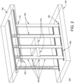
- FIG. 2 shows a portion 200 of the enclosure 100 of FIG. 1 with alternate anchor assemblies.
- the portion 200 includes the floor, 120 the ceiling, 130 and the plurality of modular supports 160.
- the modular supports 160 support electronic equipment 210 utilizing the plurality of openings disposed in the modular support 160.
- Alternate anchor assemblies include bottom anchor assemblies 220 and top anchor assemblies 230.
- Each upper end 170 and each lower end 180 of each modular support 160 are releasably secured to the bottom anchor assemblies 220 and the top anchor assemblies 230.
- Any structure with both a floor 120 and a ceiling 130 capable of supporting the load provided by the electronic equipment 210 is contemplated however embodiments according to the invention include a container 110.
- Principles of the disclosure contemplate various locations of the anchor assemblies and modular supports within the structure to contain the modular rack system, thereby allowing adjustability in the width of the space which mounts the electronic equipment 210.
- This configurability allows the supported electronic equipment 210 to be mounted in configurations specific to the application. For example, one or more rows of electronic equipment may be aligned directly adjacent to each other to allow containment and movement of warm or cold air.
- Other examples may include a space between modular supports to allow for access for an operator, mounting of rack system accessories, such as power distribution, or to provide an isolated rack enclosure for particular electronic equipment 210.
- FIG. 3A illustrates a perspective view of an embodiment of an upper or lower anchor assembly 300, which may be used in different embodiments described herein.
- FIG. 3B illustrates a top view of the assembly 300 of FIG. 3A .
- Each anchor assembly contains a base 310 which forms the basic outline of the anchor assembly 300. While a roughly square shape is illustrated in FIG. 3A and FIG. 3B , the basic shape of the base may be any shape, such as, but not limited to square, rectangle, triangle, or circular which provides adequate support for the modular support 160 to be attached.
- Each base 310 has a first side 320 with a first fastening connector 330 disposed axially to the first side 320.
- the first fastening connector 330 may be disposed axially at any point of the first side 320 of the base 310. While FIG. 3A and FIG. 3B illustrate the first fastening connector 330 disposed axially on the center of the first side 320, any location may be used.
- the first fastening connector 330 may be shaped in any way so as to be configured to be mechanically accepted by a twist lock insert assembly disposed within the floor 120, ceiling 130, upper end 170, or lower end 180 of the modular support 160.
- Connectors detailed herein while characterized as “twist locks” or “fastening connectors” are intended to represent mating mechanical connectors which may be articulated to secure the mating features without additional hardware or tools.
- Mechanical locking connections of this type and construction are contemplated in embodiments of this disclosure, including the use of the various available types, shapes, and compositions available.
- Embodiments of an upper or lower anchor assembly 300 may also contain a plurality of base mounting holes 340 disposed throughout the base 310. Such base mounting holes 340 may form patterns in the base 310 and may be at particular locations to secure the second side 325 of the base 310 to the floor 120 or the ceiling 130. Numbers and dimensions of the base mounting holes 340 may be various to support the shape of the base 310 and dimensions of any hardware used to mount the upper or lower anchor assembly 300.
- FIG. 4 illustrates a side view of an alternate embodiment of an upper or lower anchor assembly 400. While many similar features are illustrated from FIGS. 3A and 3B , a second twist lock assembly 410 is included on the second side 325 of the base 310 in the assembly 400. This second twist lock assembly 410 may be utilized to secure the upper or lower anchor assembly 400 into the floor 120 or the ceiling 130 of a container 110 or other suitable structure. It should be appreciated that the first twist lock assembly 330 and second twist lock assembly need not be identical to each other and may be offset from each other to allow desired operation.
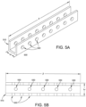
- FIG. 5A illustrates a perspective view of yet another embodiment of an upper or lower anchor assembly 500.
- FIG. 5B illustrates a top view of the assembly of FIG. 5A .
- the upper or lower anchor assembly 500 includes a "U" bracket 510 as illustrated.
- the bracket 510 has a width w to accommodate the width of a modular support 160, and the bracket 510 has a length l to accommodate application specific spacing of modular supports 160 and dimensions of the container 110 or other structure used for the overall system.
- the anchor assembly 500 may also have one or more base support holes 530 to secure the upper or lower anchor assembly 500 to the floor 120 or ceiling 130. Securing the upper or lower anchor assembly 500 may be accomplished by hardware appropriate for the construction of the floor 120 or ceiling 130. Numbers and dimensions of the base support holes 530 may be various to support the shape of the upper or lower anchor assembly 500 and dimensions of any hardware used for mounting. It should be appreciated that various hardware types contemplated in embodiments of this disclosure may be used to secure the upper or lower anchor assembly 500 to the floor 120 or ceiling 130.
- each support may also have modular support holes 520 which secure the modular support 160 placed within the upper or lower anchor assembly 500 using different types of hardware.
- Numbers and dimensions of the modular support holes 520 may be various to support the shape of the upper or lower anchor assembly 500 and dimensions of any hardware used for mounting. It should be appreciated that various hardware types are contemplated in embodiments of this disclosure and used to secure and releasably secure the modular support 160 to the upper or lower anchor assembly 500.
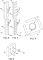
- FIGS. 6 and 7 illustrate perspective views of modular supports 610, 620, 710 and 720 which may used in place of supports discussed above in embodiments of a modular rack system.
- Embodiments of a modular support may be constructed of a single piece 160, may contain an upper modular support 610, 710 and a lower modular support 620, 720, or multiple support sections.
- An upper modular support 610, 710 will have an upper end 170 that secures to an upper anchor assembly and a lower modular support 620, 720 will have a lower end 180 that secures to a lower anchor assembly, embodiments of which are detailed herein. Should a modular support comprise three or more sections, only the uppermost and lowermost will be secured to an upper or lower anchor assembly.
- a modular support 160 constructed of more than one piece 600, 700 may be adjusted to a particular height based on the container 110 or other structure designated to house the modular rack system.
- Components of the modular support such as an upper modular support 610, 710 and a lower modular support 620, 720 may be constructed to be concentric such that modular support pieces fit within another modular support piece to allow the support to be adjustable to a desired height. Adjustability is achieved by extending or retracting components of the modular support to achieve a desired height.
- Fastening of the upper modular support 610, 710 and the lower modular support 620, 720 may be accomplished by placing hardware within one or more of the plurality of openings 190 at a point where the upper modular support 610, 710 and the lower modular support 620, 720 overlap.
- a plurality of openings 190 exist in each modular support 160 to mount electronic equipment 210.
- Such openings may be of various shapes for example, but not limited to, circular, oval, square, keyhole, or rectangular. Shapes, numbers and dimensions of the plurality of openings 190 may be various to support the shape and dimensions of any hardware used for mounting the electronic equipment 210 to the modular support 160.
- a modular support 160 may have a plurality of openings 190 disposed in a single column vertically aligned from upper end 170 to lower end 180 as illustrated in FIG. 6 .
- a modular support 160 may have a plurality of openings 190 disposed in two columns vertically aligned from upper end 170 to lower end 180 as illustrated in FIG. 7 700. In such latter embodiments the plurality of openings 190 may be disposed in pairs within the same horizontal plane. Other patters of the plurality of openings 190 may exist such as offset pairs or more than two openings.
- the plurality of openings 190 which exist in each modular support 160 may be disposed on the length or width of the modular support 160.
- Various shape openings may be disposed in various patterns on each side of the modular support.
- round openings may be disposed on the width of the modular support 160 to support electronic equipment 210
- keyhole openings may be disposed on the length, near the ends of the modular support 160 to accommodate the securing of modular rack system accessories for example, but not limited to, modular power distribution. It should be appreciated there is wide variability in the type, location, and disposition pattern of the plurality of openings 190 on the modular support 160.
- FIG. 8 An exploded perspective view of alternate embodiments of mounting electronic equipment 210 to a modular support 160 is illustrated in FIG. 8 .
- a modular support 160 and plurality of openings 810 are shown, each substantially square.
- a device commonly called a "cage nut” or “rack nut” 820 is inserted into any of the plurality of openings 810.
- Electronic equipment 210 may them be mounted to the modular support utilizing threaded hardware to secure the electronic equipment.
- Embodiments of "Cage nuts” and “rack nuts” are contemplated in embodiments of this disclosure for mounting electronic equipment.
- FIG. 9 Further embodiments are illustrated in the exploded perspective view for one of the plurality of openings 190 configured to mount electronic equipment of a modular rack system in FIG. 9 .
- a threaded flange assembly is disposed on each of the plurality of openings 190 for each modular support 160.
- Such a device may be integrated mounting hardware for mounting electronic equipment 210. Such a device may only require a mating hardware component to secure electronic equipment thereby limiting the necessary hardware to complete a system.
- a modular support 160 with a plurality of openings 190 disposed in a single column vertically aligned from upper end 170 to lower end 180 as illustrated in FIG. 6 may be used for all modular supports in a system.
- two modular supports 160 may be used for a "two post rack" application where the electronic equipment 210 is mounted in the plurality of openings 190 between two adjacent modular supports.
- a "four post rack” example may include four modular supports 160 and may be used for an application where the electronic equipment 210 is mounted in the plurality of openings 190 between all four modular supports.
- FIGS. 1 and 2 illustrate embodiments of a "four post rack.”
- FIG. 6 Further embodiments may include use of modular supports 160 with a plurality of openings 190 disposed in a single column vertically aligned from upper end 170 to lower end 180 as illustrated in FIG. 6 and modular supports 160 which have a plurality of openings 190 disposed in two columns vertically aligned from upper end 170 to lower end 180 as illustrated in FIG. 7 .
- modular supports with a plurality of openings 190 disposed in a single column vertically aligned from upper end 170 to lower end 180 may be located on the end of the modular rack system.
- Modular supports with a plurality of openings 190 disposed in two columns vertically aligned from upper end 170 to lower end 180 may be located in interior portions of the modular rack system.
- a substantial less amount of modular rack system hardware is needed to mount electronic equipment 210 as fewer modular supports are required as each interior modular support can act as a support for two adjacent stacks of equipment.
- a modular support twist lock insert assembly 1010 may be provided (see, FIGS. 10A and 10B ).
- This modular support twist lock insert assembly 1010 is the mechanical mate to the first fastening connector 330 and may be disposed axially at any point of the first side 320 of the base 310.
- This first fastening connector 330 may be shaped in any way so as to be configured to be mechanically accepted by the modular support twist lock insert assembly 1010. It should be appreciated each of the upper end 170 and the lower end 160 of the modular support 160 may contain such a modular support twist lock insert assembly 1010.
- embodiments utilizing lower and upper anchor assemblies illustrated in FIG. 4 which possess a second fastening connector 410 may utilize a container twist lock insert assembly disposed within the floor 120, ceiling 130, of a container 110 to contain the modular rack system.
- Principles of the disclosure contemplate these embodiments which allow for substantial flexibility in deployment of a modular rack system.
- connectors detailed herein while characterized as “twist locks” or “fastening connectors” are intended to represent mating mechanical connectors which may be articulated to secure the mating features without additional hardware or tools.
- Various embodiments of mechanical locking connections of this type and construction are contemplated in this disclosure, including the use of the various available types, shapes, and composition.
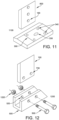
- FIG. 11 illustrates an exploded perspective view of components 1100 for an assembled modular support and anchor assembly utilizing a "twist lock" anchor assembly.
- Various embodiments utilize an upper or lower anchor assembly 300 secured to a floor 120 or ceiling 130 through a plurality of base mounting holes 340.
- the modular support 600 with a modular support twist lock insert assembly 1010 is operatively connected to a first fastening connector 330.
- an upper or lower anchor assembly 300 may be secured utilizing lower and upper anchor assemblies illustrated in FIG. 4 which possess a second fastening connector 410 and may utilize a container twist lock insert assembly disposed within the floor 120, ceiling 130, of a container 110 to contain the modular rack system.
- a modular support 600 with a modular support twist lock insert assembly 1010 is operatively connected to a first fastening connector 330.
- FIG. 12 illustrates an exploded perspective view of components 1200 for an assembled modular support and anchor assembly utilizing a "U" bracket.
- Various embodiments utilize an upper or lower "U" bracket anchor assembly 500 secured to a floor 120 or ceiling 130 through a plurality of base support holes 530.
- a modular support 700 with mounting hardware 1210 such as screws or bolts are passed through support holes 520 which secure the modular support 700 placed within the upper or lower anchor assembly 500.
- Such mounting hardware 1210 is secured by the appropriate hardware fastener 1220 to secure the modular support.
- mounting hardware 1210 and hardware fasteners 1120 may be secured by the use of tools, for example, nuts, bolts, screws, or washers.
- Such hardware may also releasably secure the modular support and utilize, for example, spring pins, or other such hardware without the use of tools.
- a modular rack system may exist utilizing compatible anchor assemblies, modular supports, and connecting hardware.
- Embodiments of anchor assemblies may be used in combinations to provide various mounting options of electronic equipment or other accessories.
- a modular support 160 with a plurality of openings 190 disposed in a single column vertically aligned from upper end 170 to lower end 180 as illustrated in FIG. 6 600 may be used for all modular supports in a system.
- two modular supports 160 may be used for a "two post rack" application where the electronic equipment 210 is mounted in the plurality of openings 190 between two adjacent modular supports.
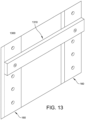
- FIG. 13 illustrates a perspective view of a cross member assembly assembled with a modular support 1300 in accordance with various embodiments of this disclosure.
- a cross member assembly 1310 may be configured to provide additional mechanical support between modular supports 160 in the event of additional loading within the modular supports. It should be appreciated the cross member assemblies 1310 may be configured in any position on any modular support 160 to effect the necessary additional stabilization for the installed electronic equipment.
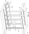
- a cantilever assembly 1410 is shown being releasably secured to the modular supports 160 of a modular rack system 1400.
- the cantilever assembly 1410 is configured to support various types of electronic equipment, such as bus bar assembly, network basket, power ladders, and other means of distribution or conveyance.
- the cantilever assembly 1410 includes two arms, each indicated at 1420, and several cross members 1430.
- Each arm 1420 is configured to be releasably secured to the modular supports 160 by fasteners at a desired elevation along lengths of the modular supports 160.
- Cross members 1430 are secured to the arms 1420 by fasteners as well.
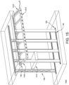
- FIG. 15 illustrates the cantilever assembly 1410 supporting an electrical power distribution unit 1510.
- Other objects may be supported by the cantilever assembly 1410 as detailed infra and are contemplated in embodiments of this disclosure.
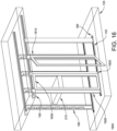
- FIG. 16 illustrates a perspective view of a door frame and door assembly mounted to a modular rack system in accordance with various embodiments of this disclosure.
- a modular rack system may further include at least one door frame assembly 1610 between assembled modular supports 160.
- FIG. 16 illustrates two door frame assemblies 1620; however, it should be appreciated that any appropriately sized construction of modular supports 160 may allow for a door frame assembly 1610 to be utilized.
- a door frame assembly 1610 includes two vertical supports 1620 and a horizontal support 1630. Each door fame assembly 1610 is configured to support one door that provides access to the electronic equipment 210.
- Alternate embodiments of the modular rack system may further include one or more blanking panels releasably secured to the modular supports 160. Such panels may be used to enclose the modular rack system to maintain air containment or security. Blanking panels may be fabricated from clear, translucent, opaque, or transparent materials which mount between modular supports 160 in locations where electronic equipment 210 is not present to maintain the intended thermal characteristic separation or prevent unauthorized access. A blanking panel may be sized based on the dimensions of the rack space intended to be "blanked" or be a variable size component.
- kits to be assembled and installed by the end user may be provided as a kit to be assembled and installed by the end user.
- a kit is configured to mount electronic equipment and include a bottom anchor assembly, a top anchor assembly, a modular support with an upper end, a lower end, and a plurality of openings configured to mount electronic equipment, a bottom anchor assembly configured to be secured to a floor and releasably secure the lower end of the modular support, a top anchor assembly configured to be secured to a ceiling and releasably secure the upper end of the modular support, and a cantilever assembly releasably secured to the modular support at an elevation along a height of the modular support, the cantilever assembly configured to support electronic equipment.
- Such a modular rack system kit further includes a plurality of bottom anchor assemblies, a plurality of top anchor assemblies, a plurality of modular supports where each modular support has an upper end a lower end, and a plurality of openings disposed therein and configured to mount equipment, and the plurality of modular supports is extended and retracted to achieve a height.
- the kit may further include a plurality of cable management assemblies configured to be supported by the plurality of modular supports, a plurality of blanking panels releasably secured to the plurality of modular supports to enclose a space defined by the plurality of modular supports, or a door frame assembly disposed between the plurality of modular supports, the door frame assembly including two vertical supports and a horizontal support, the door fame assembly being configured to support one or more doors.
- modular rack system of embodiments of the present disclosure may be used to control the flow of cooling or exhaust air from equipment and may be used to provide security of the contained electronic devices by enclosing same with the use of blanking panels, door assemblies 1610, and other associated devices to maintain the privacy and security of the devices contained within the modular rack system.
- Modular rack systems described herein provide a highly configurable support structure on which a variety of equipment may be implemented.
- Modular rack systems disclosed herein simplify the design of new or existing data center buildings, containers, or enclosures, to eliminate or reduce a reliance on the structure of a building to support the electronic equipment 210, the means of conveyance and distribution for the electronic equipment, to eliminate or reduce a need to use data center equipment to support the means of support, conveyance, or distribution, to enable the reduction of structures such as racks and rack equipment that may not be originally designed for data center use, or to save a data center business, time and money in building or outfitting a data center.
- At least some modular rack systems disclosed herein may be assembled with a minimal number of tools, or no tools, by a minimum number of personnel.
Landscapes
- Engineering & Computer Science (AREA)
- Microelectronics & Electronic Packaging (AREA)
- Computer Hardware Design (AREA)
- General Engineering & Computer Science (AREA)
- Casings For Electric Apparatus (AREA)
Claims (14)
- Ein modulares Container-Datenzentrum-Racksystem (100), das konfiguriert ist, um elektronische Ausrüstung zu installieren, und Folgendes beinhaltet:eine Containerstruktur (110) mit einem Boden (120) und einer Decke (130), die konfiguriert ist, um ein modulares Racksystem unterzubringen,eine Vielzahl von unteren Verankerungsanordnungen (140), die in dem Boden (120) der Containerstruktur (110) angeordnet sind,eine Vielzahl von oberen Verankerungsanordnungen (150), die in der Decke (130) der Containerstruktur (110) angeordnet sind, undeine Vielzahl von modularen Stützen (160), die jeweils ein höheres Ende (170) aufweisen, das konfiguriert ist, um an einer der Vielzahl von in der Decke (130) der Containerstruktur (110) angeordneten oberen Verankerungsanordnungen (150) entfernbar fixiert zu werden, wobei jede der Vielzahl von modularen Stützen (160) ausziehbar und einziehbar ist, um eine gewünschte Höhe zu erreichen, und ein tieferes Ende (180), das konfiguriert ist, um an einer der Vielzahl von in dem Boden (120) der Containerstruktur (110) angeordneten unteren Verankerungsanordnungen (140) entfernbar fixiert zu werden, und eine Vielzahl von Öffnungen (190), die konfiguriert sind, um elektronische Ausrüstung zu installieren, aufweist,wobei die Vielzahl von modularen Stützen (160) in der Containerstruktur (110) arrangiert ist, um ein Ausrüstungsrack zu bilden, und die Konfigurierbarkeit des modularen Racksystems (100) ermöglicht, dass die gestützte elektronische Ausrüstung in für die Anwendung spezifischen Konfigurationen installiert wird.
- Modulares Racksystem (100) gemäß Anspruch 1, das ferner eine Drehverschlusseinsatzanordnung beinhaltet, die in dem höheren Ende (170) jeder der Vielzahl von modularen Stützen (160) und in dem tieferen Ende (180) jeder der Vielzahl von modularen Stützen (160) axial angeordnet ist.
- Modulares Racksystem gemäß Anspruch 2, wobei jede der Vielzahl von unteren Verankerungsanordnungen (140) und jede der Vielzahl von oberen Verankerungsanordnungen (150) eine Basis (310) mit einer ersten Seite (320), einer zweiten Seite (325) und einem ersten Befestigungsverbinder (330) umfasst, wobei der erste Befestigungsverbinder (330) auf der ersten Seite (320) der Basis (310) axial angeordnet ist und konfiguriert ist, um das tiefere Ende (180) einer der Vielzahl von modularen Stützen 160) oder das höhere Ende (170) einer der Vielzahl von modularen Stützen (160) unter Nutzung einer Drehverschlusseinsatzanordnung betriebsfähig zu verbinden und lösbar zu fixieren.
- Modulares Racksystem (100) gemäß Anspruch 3, das ferner Folgendes beinhaltet: eine Containerdrehverschlusseinsatzanordnung, die innerhalb des Bodens (120) oder der Decke (130) der Containerstruktur (110) angeordnet ist, und einen zweiten Befestigungsverbinder (410), der auf der zweiten Seite (325) der Basis (310) axial angeordnet ist und konfiguriert ist, um die Basis (310) der Vielzahl von unteren Verankerungsanordnungen (140) und der Vielzahl von oberen Verankerungsanordnungen (150) mit dem Boden (120) oder der Decke (130) der Containerstruktur (110) unter Nutzung der darin angeordneten Containerdrehverschlusseinsatzanordnung betriebsfähig zu verbinden und lösbar zu fixieren.
- Modulares Racksystem (100) gemäß Anspruch 1, wobei jede der Vielzahl von unteren Verankerungsanordnungen (140) und der Vielzahl von oberen Verankerungsanordnungen (150) eine "U"-Halterung (510) umfasst, die an dem Boden (120) oder der Decke (130) der Containerstruktur (110) angeordnet ist und konfiguriert ist, um das tiefere Ende (180) einer der Vielzahl von modularen Stützen (160) oder das höhere Ende (170) einer der Vielzahl von modularen Stützen (160) lösbar zu fixieren, und an dem Boden (120) oder der Decke (130) der Containerstruktur (110) fixiert ist.
- Modulares Racksystem (100) gemäß Anspruch 1, das ferner mindestens eine Querstrebe beinhaltet, die lösbar zwischen zwei der Vielzahl von modularen Stützen (160) fixiert ist.
- Modulares Racksystem (100) gemäß Anspruch 1, wobei jede der Vielzahl von Öffnungen (190) in der Vielzahl von modularen Stützen (160) eine Gewindeflanschanordnung umfasst.
- Modulares Racksystem (100) gemäß Anspruch 1, wobei Öffnungen (190) der Vielzahl von Öffnungen (190) in der Vielzahl von modularen Stützen (160) in Paaren innerhalb einer gleichen horizontalen Ebene in einer gleichen Höhe über dem Boden (120) angeordnet sind.
- Modulares Racksystem gemäß Anspruch 1, wobei jede der Vielzahl von modularen Stützen konfiguriert ist, um Kabelverwaltungsausrüstung zu stützen.
- Modulares Racksystem (100) gemäß Anspruch 1, das ferner eine Auslegeranordnung (1410) beinhaltet, die eine Vielzahl von Armen (1420) und eine Vielzahl von lösbar an dem modularen Racksystem fixierten Stützen aufweist, wobei die Auslegeranordnung (1410) konfiguriert ist, um elektronische Ausrüstung (210) zu stützen.
- Modulares Racksystem (100) gemäß Anspruch 10, das ferner eines von einer Sammelschienenanordnung, einem Netzwerkkorb und einer Stromleiter, die/der mit der Auslegeranordnung (1410) gekoppelt ist, beinhaltet.
- Modulares Racksystem (100) gemäß Anspruch 1, das ferner eine lösbar an einer der Vielzahl von modularen Stützen (160) fixierte Abdeckplatte beinhaltet, um einen von zwei der Vielzahl von modularen Stützen (160) definierten Raum zu umschließen.
- Modulares Racksystem (100) gemäß Anspruch 1, das ferner eine Türrahmenanordnung (1610) beinhaltet, die zwischen zwei der Vielzahl von modularen Stützen (160) angeordnet ist, wobei die Türrahmenanordnung (1610) zwei vertikale Stützen (1620) und eine horizontale Stütze (1630) umfasst, wobei die Türrahmenanordnung (1610) konfiguriert ist, um eine oder mehrere Türen zu stützen.
- Ein Verfahren zum Einbauen eines modularen Container-Datenzentrum-Racksystems (100) gemäß einem der vorhergehenden Ansprüche, das Folgendes umfasst:Einbauen einer Vielzahl von unteren Verankerungsanordnungen (140) in einem Boden (120) der Containerstruktur (110);Einbauen einer Vielzahl von oberen Verankerungsanordnungen (150) in einer Decke (130) der Containerstruktur (110);Einbauen einer modularen Stütze (160) mit einem höheren Ende (170) und einem tieferen Ende (180), wobei das Einbauen einer modularen Stütze (160) das Anpassen der modularen Stütze (160), um eine Höhe zu erreichen, das Eingliedern eines tieferen Endes der modularen Stütze (160) in die untere Verankerungsanordnung und das Eingliedern eines höheren Endes der modularen Stütze in die obere Verankerungsanordnung umfasst; undEinbauen von elektronischer Ausrüstung (210) zwischen benachbart eingebauten modularen Stützen (160).
Applications Claiming Priority (1)
| Application Number | Priority Date | Filing Date | Title |
|---|---|---|---|
| US15/227,467 US10499535B2 (en) | 2016-08-03 | 2016-08-03 | Modular rack system |
Publications (2)
| Publication Number | Publication Date |
|---|---|
| EP3280232A1 EP3280232A1 (de) | 2018-02-07 |
| EP3280232B1 true EP3280232B1 (de) | 2023-05-03 |
Family
ID=59579393
Family Applications (1)
| Application Number | Title | Priority Date | Filing Date |
|---|---|---|---|
| EP17184169.5A Active EP3280232B1 (de) | 2016-08-03 | 2017-08-01 | Modulares regalsystem |
Country Status (3)
| Country | Link |
|---|---|
| US (1) | US10499535B2 (de) |
| EP (1) | EP3280232B1 (de) |
| CN (1) | CN107690254B (de) |
Families Citing this family (5)
| Publication number | Priority date | Publication date | Assignee | Title |
|---|---|---|---|---|
| US10143105B1 (en) | 2017-09-07 | 2018-11-27 | Schneider Electric It Corporation | Re-usable modular skid assembly for shipping electronic modules |
| TWI688319B (zh) * | 2019-07-29 | 2020-03-11 | 緯創資通股份有限公司 | 可限制不同模組安裝順序之電子裝置及其機殼模組 |
| US11758683B2 (en) | 2020-11-16 | 2023-09-12 | Sebastian Sanchez | Modular switch rack |
| US11758679B2 (en) * | 2021-08-24 | 2023-09-12 | Quanta Computer Inc. | Tool-less support frame for electronic component |
| US12328839B2 (en) * | 2023-04-28 | 2025-06-10 | Hewlett Packard Enterprise Development Lp | Modular rear panel system for chassis of electronic device |
Citations (1)
| Publication number | Priority date | Publication date | Assignee | Title |
|---|---|---|---|---|
| EP0057580B1 (de) * | 1981-01-30 | 1987-07-22 | Hitachi, Ltd. | Gestellanordnung für elektronische Anlagen |
Family Cites Families (20)
| Publication number | Priority date | Publication date | Assignee | Title |
|---|---|---|---|---|
| US4964020A (en) | 1989-09-27 | 1990-10-16 | At&T Bell Laboratories | Equipment rack |
| FR2761206B1 (fr) | 1997-03-21 | 1999-05-14 | Schneider Electric Sa | Chassis metallique a coin d'assemblage hyperstatique, notamment pour une ossature d'armoire electrique |
| FR2799925B1 (fr) | 1999-10-18 | 2001-11-23 | Schneider Electric Ind Sa | Montant pour une ossature metallique, notamment pour un chassis d'une armoire electrique |
| US6425488B1 (en) | 2000-04-12 | 2002-07-30 | International Business Machines Corporation | Integrated flexible frame tie down retention system for raised and non-raised floor applications |
| US7275646B2 (en) | 2000-11-07 | 2007-10-02 | Innovation First, Inc. | Apparatus and method for adapting two-post rack systems to support four-post rack mounted equipment |
| US6719150B2 (en) * | 2001-05-30 | 2004-04-13 | Kim Manufacturing Company | Battery rack and system |
| US7357262B2 (en) * | 2006-03-02 | 2008-04-15 | Fratilla Brian J | Hanging storage system |
| US20080006593A1 (en) | 2006-07-05 | 2008-01-10 | Northrop Grumman Corporation | Modular rack design |
| US7639486B2 (en) * | 2007-12-13 | 2009-12-29 | International Business Machines Corporation | Rack system providing flexible configuration of computer systems with front access |
| US8215498B2 (en) | 2008-04-30 | 2012-07-10 | Raytheon Company | Modular rack system |
| US8184435B2 (en) | 2009-01-28 | 2012-05-22 | American Power Conversion Corporation | Hot aisle containment cooling system and method |
| US8031468B2 (en) | 2009-06-03 | 2011-10-04 | American Power Conversion Corporation | Hot aisle containment cooling unit and method for cooling |
| US8193448B2 (en) | 2009-10-29 | 2012-06-05 | American Power Conversion Corporation | Systems and methods of managing cables |
| WO2011106842A1 (en) * | 2010-03-03 | 2011-09-09 | Modconnect Group Pty Ltd | Improvements in prefabricated modular building units |
| US9670689B2 (en) | 2010-04-06 | 2017-06-06 | Schneider Electric It Corporation | Container based data center solutions |
| US8833711B2 (en) | 2010-04-27 | 2014-09-16 | Panduit Corp. | Two post rack with floor mounting brackets |
| WO2013159157A1 (en) | 2012-04-27 | 2013-10-31 | Meshblox Pty Ltd | Equipment installation systems for portable modular enclosed environments |
| GB201412452D0 (en) | 2014-07-14 | 2014-08-27 | Houlding Graham | Panel apparatus and method of use thereof |
| US9572276B2 (en) * | 2014-11-06 | 2017-02-14 | Cinnos Technologies, Inc. | Smart mission critical rack |
| US9420884B2 (en) * | 2015-01-12 | 2016-08-23 | Jak Holdings, Llc | Overhead storage rack |
-
2016
- 2016-08-03 US US15/227,467 patent/US10499535B2/en active Active
-
2017
- 2017-08-01 EP EP17184169.5A patent/EP3280232B1/de active Active
- 2017-08-03 CN CN201710654917.7A patent/CN107690254B/zh active Active
Patent Citations (1)
| Publication number | Priority date | Publication date | Assignee | Title |
|---|---|---|---|---|
| EP0057580B1 (de) * | 1981-01-30 | 1987-07-22 | Hitachi, Ltd. | Gestellanordnung für elektronische Anlagen |
Also Published As
| Publication number | Publication date |
|---|---|
| CN107690254B (zh) | 2020-12-01 |
| CN107690254A (zh) | 2018-02-13 |
| US20180042133A1 (en) | 2018-02-08 |
| US10499535B2 (en) | 2019-12-03 |
| EP3280232A1 (de) | 2018-02-07 |
Similar Documents
| Publication | Publication Date | Title |
|---|---|---|
| EP3280232A1 (de) | Modulares regalsystem | |
| US10531591B2 (en) | Data center racks and structural framework for electronic equipment and non-electronic equipment | |
| US8913393B2 (en) | Wall-mountable support rack for equipment | |
| US20210307183A1 (en) | Vertical mounting rail with cable management features | |
| US6101773A (en) | Wire management system | |
| US20110155674A1 (en) | Six-Post Telecommunications Equipment Rack | |
| US9131771B2 (en) | Sliding drawer assembly for use with gondola shelving systems | |
| US20080037228A1 (en) | Electronic equipment cabinet expansion kit with offset brackets | |
| US9408325B2 (en) | Center pivot swing-out wall rack | |
| US20150282349A1 (en) | Equipment rack bracing | |
| US20180092227A1 (en) | Equipment rack support and stabilization system | |
| EP3429218B1 (de) | Zwischenverteilungsrahmengehäuse mit falschen säulen | |
| US20080264880A1 (en) | Apparatus and Method for Housing Electronic Equipment and Increasing Floor Space Utilization | |
| WO2015077858A1 (pt) | Poste de iluminação com compartimento interno encaixado na sua base para equipamentos de telecomunicação | |
| US20050024842A1 (en) | Electronic enclosure and mounting arrangement therefor | |
| CN110139528A (zh) | 一种适用于机房的综合布线方法 | |
| CN213126728U (zh) | 一种机柜 | |
| US20170150632A1 (en) | Rack mountable security enclosures | |
| CN217523106U (zh) | 一种pc数据网络机柜 | |
| AU2004203819A1 (en) | Rack and Duct System | |
| WO2022072573A1 (en) | Adjustable center post for multi-door enclosures | |
| CN213755186U (zh) | 一种侧面安装电子部件的机柜 | |
| CN216932304U (zh) | 一种便于运输和搬运的控制台 | |
| RU52047U1 (ru) | Сборная металлоконструкция фальшпола | |
| US20100308189A1 (en) | Latching System for Multiple Nodes of a Computer System |
Legal Events
| Date | Code | Title | Description |
|---|---|---|---|
| PUAI | Public reference made under article 153(3) epc to a published international application that has entered the european phase |
Free format text: ORIGINAL CODE: 0009012 |
|
| STAA | Information on the status of an ep patent application or granted ep patent |
Free format text: STATUS: REQUEST FOR EXAMINATION WAS MADE |
|
| 17P | Request for examination filed |
Effective date: 20170801 |
|
| AK | Designated contracting states |
Kind code of ref document: A1 Designated state(s): AL AT BE BG CH CY CZ DE DK EE ES FI FR GB GR HR HU IE IS IT LI LT LU LV MC MK MT NL NO PL PT RO RS SE SI SK SM TR |
|
| AX | Request for extension of the european patent |
Extension state: BA ME |
|
| STAA | Information on the status of an ep patent application or granted ep patent |
Free format text: STATUS: EXAMINATION IS IN PROGRESS |
|
| 17Q | First examination report despatched |
Effective date: 20210113 |
|
| GRAP | Despatch of communication of intention to grant a patent |
Free format text: ORIGINAL CODE: EPIDOSNIGR1 |
|
| STAA | Information on the status of an ep patent application or granted ep patent |
Free format text: STATUS: GRANT OF PATENT IS INTENDED |
|
| INTG | Intention to grant announced |
Effective date: 20221122 |
|
| GRAS | Grant fee paid |
Free format text: ORIGINAL CODE: EPIDOSNIGR3 |
|
| GRAA | (expected) grant |
Free format text: ORIGINAL CODE: 0009210 |
|
| STAA | Information on the status of an ep patent application or granted ep patent |
Free format text: STATUS: THE PATENT HAS BEEN GRANTED |
|
| RAP3 | Party data changed (applicant data changed or rights of an application transferred) |
Owner name: SCHNEIDER ELECTRIC IT CORPORATION |
|
| AK | Designated contracting states |
Kind code of ref document: B1 Designated state(s): AL AT BE BG CH CY CZ DE DK EE ES FI FR GB GR HR HU IE IS IT LI LT LU LV MC MK MT NL NO PL PT RO RS SE SI SK SM TR |
|
| REG | Reference to a national code |
Ref country code: GB Ref legal event code: FG4D |
|
| REG | Reference to a national code |
Ref country code: DE Ref legal event code: R096 Ref document number: 602017068243 Country of ref document: DE |
|
| REG | Reference to a national code |
Ref country code: AT Ref legal event code: REF Ref document number: 1565789 Country of ref document: AT Kind code of ref document: T Effective date: 20230515 Ref country code: CH Ref legal event code: EP |
|
| REG | Reference to a national code |
Ref country code: IE Ref legal event code: FG4D |
|
| REG | Reference to a national code |
Ref country code: LT Ref legal event code: MG9D |
|
| REG | Reference to a national code |
Ref country code: NL Ref legal event code: MP Effective date: 20230503 |
|
| REG | Reference to a national code |
Ref country code: AT Ref legal event code: MK05 Ref document number: 1565789 Country of ref document: AT Kind code of ref document: T Effective date: 20230503 |
|
| PG25 | Lapsed in a contracting state [announced via postgrant information from national office to epo] |
Ref country code: SE Free format text: LAPSE BECAUSE OF FAILURE TO SUBMIT A TRANSLATION OF THE DESCRIPTION OR TO PAY THE FEE WITHIN THE PRESCRIBED TIME-LIMIT Effective date: 20230503 Ref country code: PT Free format text: LAPSE BECAUSE OF FAILURE TO SUBMIT A TRANSLATION OF THE DESCRIPTION OR TO PAY THE FEE WITHIN THE PRESCRIBED TIME-LIMIT Effective date: 20230904 Ref country code: NO Free format text: LAPSE BECAUSE OF FAILURE TO SUBMIT A TRANSLATION OF THE DESCRIPTION OR TO PAY THE FEE WITHIN THE PRESCRIBED TIME-LIMIT Effective date: 20230803 Ref country code: NL Free format text: LAPSE BECAUSE OF FAILURE TO SUBMIT A TRANSLATION OF THE DESCRIPTION OR TO PAY THE FEE WITHIN THE PRESCRIBED TIME-LIMIT Effective date: 20230503 Ref country code: ES Free format text: LAPSE BECAUSE OF FAILURE TO SUBMIT A TRANSLATION OF THE DESCRIPTION OR TO PAY THE FEE WITHIN THE PRESCRIBED TIME-LIMIT Effective date: 20230503 Ref country code: AT Free format text: LAPSE BECAUSE OF FAILURE TO SUBMIT A TRANSLATION OF THE DESCRIPTION OR TO PAY THE FEE WITHIN THE PRESCRIBED TIME-LIMIT Effective date: 20230503 |
|
| PG25 | Lapsed in a contracting state [announced via postgrant information from national office to epo] |
Ref country code: RS Free format text: LAPSE BECAUSE OF FAILURE TO SUBMIT A TRANSLATION OF THE DESCRIPTION OR TO PAY THE FEE WITHIN THE PRESCRIBED TIME-LIMIT Effective date: 20230503 Ref country code: PL Free format text: LAPSE BECAUSE OF FAILURE TO SUBMIT A TRANSLATION OF THE DESCRIPTION OR TO PAY THE FEE WITHIN THE PRESCRIBED TIME-LIMIT Effective date: 20230503 Ref country code: LV Free format text: LAPSE BECAUSE OF FAILURE TO SUBMIT A TRANSLATION OF THE DESCRIPTION OR TO PAY THE FEE WITHIN THE PRESCRIBED TIME-LIMIT Effective date: 20230503 Ref country code: LT Free format text: LAPSE BECAUSE OF FAILURE TO SUBMIT A TRANSLATION OF THE DESCRIPTION OR TO PAY THE FEE WITHIN THE PRESCRIBED TIME-LIMIT Effective date: 20230503 Ref country code: IS Free format text: LAPSE BECAUSE OF FAILURE TO SUBMIT A TRANSLATION OF THE DESCRIPTION OR TO PAY THE FEE WITHIN THE PRESCRIBED TIME-LIMIT Effective date: 20230903 Ref country code: HR Free format text: LAPSE BECAUSE OF FAILURE TO SUBMIT A TRANSLATION OF THE DESCRIPTION OR TO PAY THE FEE WITHIN THE PRESCRIBED TIME-LIMIT Effective date: 20230503 Ref country code: GR Free format text: LAPSE BECAUSE OF FAILURE TO SUBMIT A TRANSLATION OF THE DESCRIPTION OR TO PAY THE FEE WITHIN THE PRESCRIBED TIME-LIMIT Effective date: 20230804 |
|
| PG25 | Lapsed in a contracting state [announced via postgrant information from national office to epo] |
Ref country code: FI Free format text: LAPSE BECAUSE OF FAILURE TO SUBMIT A TRANSLATION OF THE DESCRIPTION OR TO PAY THE FEE WITHIN THE PRESCRIBED TIME-LIMIT Effective date: 20230503 |
|
| PG25 | Lapsed in a contracting state [announced via postgrant information from national office to epo] |
Ref country code: SK Free format text: LAPSE BECAUSE OF FAILURE TO SUBMIT A TRANSLATION OF THE DESCRIPTION OR TO PAY THE FEE WITHIN THE PRESCRIBED TIME-LIMIT Effective date: 20230503 |
|
| PG25 | Lapsed in a contracting state [announced via postgrant information from national office to epo] |
Ref country code: SM Free format text: LAPSE BECAUSE OF FAILURE TO SUBMIT A TRANSLATION OF THE DESCRIPTION OR TO PAY THE FEE WITHIN THE PRESCRIBED TIME-LIMIT Effective date: 20230503 Ref country code: SK Free format text: LAPSE BECAUSE OF FAILURE TO SUBMIT A TRANSLATION OF THE DESCRIPTION OR TO PAY THE FEE WITHIN THE PRESCRIBED TIME-LIMIT Effective date: 20230503 Ref country code: RO Free format text: LAPSE BECAUSE OF FAILURE TO SUBMIT A TRANSLATION OF THE DESCRIPTION OR TO PAY THE FEE WITHIN THE PRESCRIBED TIME-LIMIT Effective date: 20230503 Ref country code: EE Free format text: LAPSE BECAUSE OF FAILURE TO SUBMIT A TRANSLATION OF THE DESCRIPTION OR TO PAY THE FEE WITHIN THE PRESCRIBED TIME-LIMIT Effective date: 20230503 Ref country code: DK Free format text: LAPSE BECAUSE OF FAILURE TO SUBMIT A TRANSLATION OF THE DESCRIPTION OR TO PAY THE FEE WITHIN THE PRESCRIBED TIME-LIMIT Effective date: 20230503 Ref country code: CZ Free format text: LAPSE BECAUSE OF FAILURE TO SUBMIT A TRANSLATION OF THE DESCRIPTION OR TO PAY THE FEE WITHIN THE PRESCRIBED TIME-LIMIT Effective date: 20230503 |
|
| REG | Reference to a national code |
Ref country code: DE Ref legal event code: R097 Ref document number: 602017068243 Country of ref document: DE |
|
| PLBE | No opposition filed within time limit |
Free format text: ORIGINAL CODE: 0009261 |
|
| STAA | Information on the status of an ep patent application or granted ep patent |
Free format text: STATUS: NO OPPOSITION FILED WITHIN TIME LIMIT |
|
| PG25 | Lapsed in a contracting state [announced via postgrant information from national office to epo] |
Ref country code: MC Free format text: LAPSE BECAUSE OF FAILURE TO SUBMIT A TRANSLATION OF THE DESCRIPTION OR TO PAY THE FEE WITHIN THE PRESCRIBED TIME-LIMIT Effective date: 20230503 |
|
| REG | Reference to a national code |
Ref country code: CH Ref legal event code: PL |
|
| PG25 | Lapsed in a contracting state [announced via postgrant information from national office to epo] |
Ref country code: MC Free format text: LAPSE BECAUSE OF FAILURE TO SUBMIT A TRANSLATION OF THE DESCRIPTION OR TO PAY THE FEE WITHIN THE PRESCRIBED TIME-LIMIT Effective date: 20230503 |
|
| 26N | No opposition filed |
Effective date: 20240206 |
|
| PG25 | Lapsed in a contracting state [announced via postgrant information from national office to epo] |
Ref country code: LU Free format text: LAPSE BECAUSE OF NON-PAYMENT OF DUE FEES Effective date: 20230801 |
|
| PG25 | Lapsed in a contracting state [announced via postgrant information from national office to epo] |
Ref country code: LU Free format text: LAPSE BECAUSE OF NON-PAYMENT OF DUE FEES Effective date: 20230801 Ref country code: CH Free format text: LAPSE BECAUSE OF NON-PAYMENT OF DUE FEES Effective date: 20230831 |
|
| PG25 | Lapsed in a contracting state [announced via postgrant information from national office to epo] |
Ref country code: SI Free format text: LAPSE BECAUSE OF FAILURE TO SUBMIT A TRANSLATION OF THE DESCRIPTION OR TO PAY THE FEE WITHIN THE PRESCRIBED TIME-LIMIT Effective date: 20230503 |
|
| REG | Reference to a national code |
Ref country code: BE Ref legal event code: MM Effective date: 20230831 |
|
| REG | Reference to a national code |
Ref country code: IE Ref legal event code: MM4A |
|
| PG25 | Lapsed in a contracting state [announced via postgrant information from national office to epo] |
Ref country code: SI Free format text: LAPSE BECAUSE OF FAILURE TO SUBMIT A TRANSLATION OF THE DESCRIPTION OR TO PAY THE FEE WITHIN THE PRESCRIBED TIME-LIMIT Effective date: 20230503 Ref country code: IT Free format text: LAPSE BECAUSE OF FAILURE TO SUBMIT A TRANSLATION OF THE DESCRIPTION OR TO PAY THE FEE WITHIN THE PRESCRIBED TIME-LIMIT Effective date: 20230503 |
|
| PG25 | Lapsed in a contracting state [announced via postgrant information from national office to epo] |
Ref country code: IE Free format text: LAPSE BECAUSE OF NON-PAYMENT OF DUE FEES Effective date: 20230801 |
|
| PG25 | Lapsed in a contracting state [announced via postgrant information from national office to epo] |
Ref country code: IE Free format text: LAPSE BECAUSE OF NON-PAYMENT OF DUE FEES Effective date: 20230801 |
|
| PG25 | Lapsed in a contracting state [announced via postgrant information from national office to epo] |
Ref country code: BE Free format text: LAPSE BECAUSE OF NON-PAYMENT OF DUE FEES Effective date: 20230831 |
|
| PG25 | Lapsed in a contracting state [announced via postgrant information from national office to epo] |
Ref country code: BG Free format text: LAPSE BECAUSE OF FAILURE TO SUBMIT A TRANSLATION OF THE DESCRIPTION OR TO PAY THE FEE WITHIN THE PRESCRIBED TIME-LIMIT Effective date: 20230503 |
|
| PG25 | Lapsed in a contracting state [announced via postgrant information from national office to epo] |
Ref country code: BG Free format text: LAPSE BECAUSE OF FAILURE TO SUBMIT A TRANSLATION OF THE DESCRIPTION OR TO PAY THE FEE WITHIN THE PRESCRIBED TIME-LIMIT Effective date: 20230503 |
|
| PG25 | Lapsed in a contracting state [announced via postgrant information from national office to epo] |
Ref country code: CY Free format text: LAPSE BECAUSE OF FAILURE TO SUBMIT A TRANSLATION OF THE DESCRIPTION OR TO PAY THE FEE WITHIN THE PRESCRIBED TIME-LIMIT; INVALID AB INITIO Effective date: 20170801 |
|
| PG25 | Lapsed in a contracting state [announced via postgrant information from national office to epo] |
Ref country code: HU Free format text: LAPSE BECAUSE OF FAILURE TO SUBMIT A TRANSLATION OF THE DESCRIPTION OR TO PAY THE FEE WITHIN THE PRESCRIBED TIME-LIMIT; INVALID AB INITIO Effective date: 20170801 |
|
| PGFP | Annual fee paid to national office [announced via postgrant information from national office to epo] |
Ref country code: DE Payment date: 20250827 Year of fee payment: 9 |
|
| PGFP | Annual fee paid to national office [announced via postgrant information from national office to epo] |
Ref country code: GB Payment date: 20250826 Year of fee payment: 9 |
|
| PGFP | Annual fee paid to national office [announced via postgrant information from national office to epo] |
Ref country code: FR Payment date: 20250825 Year of fee payment: 9 |
|
| PG25 | Lapsed in a contracting state [announced via postgrant information from national office to epo] |
Ref country code: TR Free format text: LAPSE BECAUSE OF FAILURE TO SUBMIT A TRANSLATION OF THE DESCRIPTION OR TO PAY THE FEE WITHIN THE PRESCRIBED TIME-LIMIT Effective date: 20230503 |