EP3280355B1 - Vorrichtung für proximale-zu-distale-stenteinführung - Google Patents
Vorrichtung für proximale-zu-distale-stenteinführung Download PDFInfo
- Publication number
- EP3280355B1 EP3280355B1 EP16777055.1A EP16777055A EP3280355B1 EP 3280355 B1 EP3280355 B1 EP 3280355B1 EP 16777055 A EP16777055 A EP 16777055A EP 3280355 B1 EP3280355 B1 EP 3280355B1
- Authority
- EP
- European Patent Office
- Prior art keywords
- stent
- catheter
- membrane
- proximal
- lubricous
- Prior art date
- Legal status (The legal status is an assumption and is not a legal conclusion. Google has not performed a legal analysis and makes no representation as to the accuracy of the status listed.)
- Active
Links
Images



Classifications
-
- A—HUMAN NECESSITIES
- A61—MEDICAL OR VETERINARY SCIENCE; HYGIENE
- A61F—FILTERS IMPLANTABLE INTO BLOOD VESSELS; PROSTHESES; DEVICES PROVIDING PATENCY TO, OR PREVENTING COLLAPSING OF, TUBULAR STRUCTURES OF THE BODY, e.g. STENTS; ORTHOPAEDIC, NURSING OR CONTRACEPTIVE DEVICES; FOMENTATION; TREATMENT OR PROTECTION OF EYES OR EARS; BANDAGES, DRESSINGS OR ABSORBENT PADS; FIRST-AID KITS
- A61F2/00—Filters implantable into blood vessels; Prostheses, i.e. artificial substitutes or replacements for parts of the body; Appliances for connecting them with the body; Devices providing patency to, or preventing collapsing of, tubular structures of the body, e.g. stents
- A61F2/95—Instruments specially adapted for placement or removal of stents or stent-grafts
- A61F2/962—Instruments specially adapted for placement or removal of stents or stent-grafts having an outer sleeve
- A61F2/966—Instruments specially adapted for placement or removal of stents or stent-grafts having an outer sleeve with relative longitudinal movement between outer sleeve and prosthesis, e.g. using a push rod
- A61F2/9661—Instruments specially adapted for placement or removal of stents or stent-grafts having an outer sleeve with relative longitudinal movement between outer sleeve and prosthesis, e.g. using a push rod the proximal portion of the stent or stent-graft is released first
-
- A—HUMAN NECESSITIES
- A61—MEDICAL OR VETERINARY SCIENCE; HYGIENE
- A61F—FILTERS IMPLANTABLE INTO BLOOD VESSELS; PROSTHESES; DEVICES PROVIDING PATENCY TO, OR PREVENTING COLLAPSING OF, TUBULAR STRUCTURES OF THE BODY, e.g. STENTS; ORTHOPAEDIC, NURSING OR CONTRACEPTIVE DEVICES; FOMENTATION; TREATMENT OR PROTECTION OF EYES OR EARS; BANDAGES, DRESSINGS OR ABSORBENT PADS; FIRST-AID KITS
- A61F2/00—Filters implantable into blood vessels; Prostheses, i.e. artificial substitutes or replacements for parts of the body; Appliances for connecting them with the body; Devices providing patency to, or preventing collapsing of, tubular structures of the body, e.g. stents
- A61F2/95—Instruments specially adapted for placement or removal of stents or stent-grafts
- A61F2/962—Instruments specially adapted for placement or removal of stents or stent-grafts having an outer sleeve
- A61F2/966—Instruments specially adapted for placement or removal of stents or stent-grafts having an outer sleeve with relative longitudinal movement between outer sleeve and prosthesis, e.g. using a push rod
- A61F2002/9665—Instruments specially adapted for placement or removal of stents or stent-grafts having an outer sleeve with relative longitudinal movement between outer sleeve and prosthesis, e.g. using a push rod with additional retaining means
-
- A—HUMAN NECESSITIES
- A61—MEDICAL OR VETERINARY SCIENCE; HYGIENE
- A61F—FILTERS IMPLANTABLE INTO BLOOD VESSELS; PROSTHESES; DEVICES PROVIDING PATENCY TO, OR PREVENTING COLLAPSING OF, TUBULAR STRUCTURES OF THE BODY, e.g. STENTS; ORTHOPAEDIC, NURSING OR CONTRACEPTIVE DEVICES; FOMENTATION; TREATMENT OR PROTECTION OF EYES OR EARS; BANDAGES, DRESSINGS OR ABSORBENT PADS; FIRST-AID KITS
- A61F2230/00—Geometry of prostheses classified in groups A61F2/00 - A61F2/26 or A61F2/82 or A61F9/00 or A61F11/00 or subgroups thereof
- A61F2230/0063—Three-dimensional shapes
- A61F2230/0069—Three-dimensional shapes cylindrical
Definitions
- the invention generally relates to an apparatus for the deployment of stents, and more particularly, for aligning and installing stents with high accuracy by proximal-to-distal deployment.
- the methods of using the apparatus disclosed in the present application do not form part of the present invention, they are considered useful for understanding the invention.
- stents to overcome weakness in the walls of lumens within the human body and to open up blood vessels constricted by plaque to improve blood flow, have been in existence for some time now.
- These stents comprise both open stents and medicated or covered stents.
- the accurate placement of these stents within the lumen is a very difficult, but accurate placement of these stents is important to repair any defective regions on the side wall of the lumens.
- stents are used to keep the blood vessels with plaque deposit open to prevent problems related to blood supply to the organs.
- deployment devices have been developed for accurate placement of stents in human body lumens. Many of the deployment devices are used for placement of the newer self-expanding type of stents. Most placement devices have an inner catheter with a section designated to hold a crimped stent over it at the distal end, covered by an outer catheter slidably deposed over the inner catheter to hold the crimped stent in place until deployment. A guide wire through and within the inner catheter is used as a guide to insert and guide the stent deployment device to the location where the stent will be deployed. Once at the location, the outer catheter is pulled back from over the stent to expose and deploy the stent at the location. Typically, the deployment is a distal-to-proximal deployment or a central-to-edge deployment.
- Placement of the proximal edge of the stent accurately at a proximal location is critical in certain scenarios, including, for example, deployment of the self-expanding stent at a location where a side branch of a lumen originates and the side branch is not to be covered; deployment of the stent so that it overlaps another previously installed stent proximally; and deployment of the stent to cover the ostia of a lumen.
- the proximal to distal deployment will also be very useful in iliac stenting and during Endovascular (abdominal aortic) aneurysm repair (EVAR) procedures.
- US2002/0077691 discloses an expandable stent to be positioned and implanted at the intersection of a great vessel and a branch vessel.
- a sheath holds the stent in a compressed state during delivery and a retainer holds the stop in an undeployed position while the delivery system is advanced to a desired location at the intersection of the great vessel and the branch vessel.
- US2010/069852 discloses a catheter that comprises a sheath that is connected at opposing ends to concentric tubes that move relative to each other in a manner that alternatively covers and exposes a medical device loaded onto the catheter. A portion of the sheath is arranged so as to invert upon itself so that axial movement of one tube relative to the other simultaneously moves the inversion point over or away from the device, alternatively covering or exposing the device.
- proximal to distal stent placement devices have been disclosed, they do not provide the ease of placement or the capability to pre-define and establish the position of the proximal edge of the stent with respect to the location of the lumen prior to deployment for an accurate proximal-to-distal placement.
- a stent deployment system with the capability to monitor the proximal placement location prior to deployment, to ensure accurate placement with critical proximal stent positioning is disclosed.
- the stent delivery and deployment device described herein is used to accurately place a stent within a lumen through a procedure using a stent deployment method that is proximal to distal allowing accurate placement of the proximal edge.
- the deployment device also lets the operator check and align the proximal and distal position of the stent to allow for accurate positioning within the lumen.
- a method includes delivering a stent deployment device to a treatment location, the stent deployment device comprising an inner catheter, an outer catheter, a stent attached to the outer catheter, a membrane covering the stent, a ring attached to a distal end of the membrane, and a plurality of wires attached to the ring and extending through a space between the inner catheter and the outer catheter; aligning a proximal edge of the stent to the treatment location; and retracting the ring and the membrane into the space between the inner catheter and the outer catheter using the pull wires to expand the stent from its proximal end to its distal end.
- a stent deployment system includes an inner catheter 6 slideably movable over a guide wire 7; an outer catheter 4 slideably moveable over the inner sheath such that an interspace if formed between the inner catheter 6 and the outer catheter 4; an expandable stent 3 crimped on the outer sheath; a lubricous elastic membrane 2 removably covering the stent 3, the lubricous elastic membrane 2 having a proximal end and a distal end; a ring 8 slidably deployed over the inner catheter and retractable into the interspace, the ring attached to the distal end of the lubricous elastic membrane 2; a plurality of pull wires 5 connected to the ring 8, for retracting the ring and elastic membrane 2 into the interspace.
- the system may further include a sheath catheter 1, the outer catheter 4 slideably movable within the sheath catheter 1.
- the system further includes the guide wire 7.
- the plurality of pull wires 5 may include two pull wires.
- the system may further include a pull mechanism connected to the proximal end of the pull wires 5 and for applying a pullback force for retracting the ring 8 and elastic membrane 2 into the interspace.
- the membrane 2 may be invertible.
- the stent deployment device includes an inner catheter 6, an outer catheter 4 and a sheath catheter 1 over a guide wire 7.
- the outer catheter tube is deployed in a slidable/ movable manner within the sheath catheter tube.
- An accurately adjustable slide mechanism associated with the outer catheter 4 and the sheath catheter 1 enable the accurate positioning of the outer catheter 4 with reference to the distal end of the sheath catheter 1.
- the guide wire, 7 which is inserted into the inner catheter 6, provides a guide for the deployment device to the correct location.
- a crimped stent is deposed over the distal end of the outer catheter 4.
- the crimped stent is held in its compressed position on the outer catheter 4 by a lubricous elastic membrane 2 attached to a retractable ring 8 with pull wires 5.
- the highly lubricous elastic and transparent membrane is in the form of a cover.
- One end of the cover is attached to the ring 8 deployed over the inner catheter 6, such that it can move freely within the space between the outer and inner catheters.
- the ring itself is drawn back into the interspace between the inner and outer catheters using a multiple of pull wires 5 that extend within the space between the inner and outer catheters.
- the pull wires 5 extend in the inter space between the inner catheter 6 and the outer catheter 4.
- a pull back mechanism is connected to the proximal ends of the pull wires and attached to the proximal end of the deployment device. The pull back mechanism is used to exert uniform pull force on the ring 8 for retracting the ring when needed.
- the lubricous elastic membrane 2 is pulled back by pulling the ring back using the pull wires 5 into the space between the inner catheter 6 and the outer catheter 4, releasing the stent in a controlled fashion from proximal-to-distal end.
- the self-expanding stent 3 is allowed to expand.
- the membrane 2 covers and retains the stent 3 in a crimped state over the outer catheter 4 prior to retraction.
- the accurate placement of the stent is accomplished by initially fixing the location of the proximal end.
- the wires 5 connected to the ring 8 to which the lubricous elastic membrane 2 is connected are drawn in, pulling the lubricous elastic membrane 2 with it into the interspace of the inner and outer catheters.
- the membrane gets drawn in, it releases the proximal end of the stent allowing it to deploy at the location from the proximal-to-distal end. Since the stent was aligned before the membrane is pulled back, the location of the proximal end can be accurately fixed.
- Additional visual and irrigation capability are provided through the catheters as known to those of skill in the art to visually observe the placement of the stent and to irrigate the location and the stent as needed.
- proximal to distal deployable stent and deployment mechanism disclosed herein may be used in the proximal superficial femoral artery (SFA). It will be appreciated that the deployment system may be used in a number of other procedures, including, but not limited to, during iliac stenting and during Endovascular (abdominal aortic) aneurysm repair (EVAR).
- SFA proximal superficial femoral artery
- EVAR Endovascular (abdominal aortic) aneurysm repair
- This proximal to distal stent is also usable for accurate deployment of stent during venous stenting, to avoid stenting across major vein bifurcations (the confluence of the internal jugular vein with the innominate vein when stenting from an upper extremity approach).
- Accuracy of stent placement is necessary to prevent stenting across the internal jugular vein in dialysis patients when treating a stenosis of the innominate or subclavian veins which are central and peripheral to the internal jugular vein respectively. This becomes critical because the internal jugular vein is literally the lifeline for dialysis catheter placement if the upper extremity dialysis fistula fails in these patients.
- Fig. 1 shows a diagram of a stent deployment device 100
- Fig. 2 is a cross-sectional view 200 of the device 100 at section A-A
- the stent deployment device 100 includes a sheath catheter 1, an elastic lubricous membrane 2, a stent 3, an outer catheter 4, pull wires 5, an inner catheter 6, a guide wire 7, and a ring 8.
- the guide wire 7 is used to ensure that the stent deployment device 100 is guided through the body lumen from entry point to the correct location.
- the guidance and stent deployment is typically conducted under X-ray monitoring.
- the expandable stent 3 is shown in a crimped state in Figs. 1 and 2 , placed over the outer catheter 4.
- the crimped stent is covered by the elastic lubricous membrane 2 that is in the form of an open ended bag.
- the elastic lubricous material forming the elastic lubricous membrane 2 is typically formed of a reinforced stretchable nylon that is coated by a lubricant material.
- the inner catheter 6 is positioned over the guide wire 7, typically having a stainless steel wire of a 0.014 inch (0.3556 mm) diameter.
- the sheath catheter 1 provides protection to the elastic lubricous membrane 2, covering the crimped-stent 3. It will be appreciated that although the sheath catheter 1 is shown in Figs. 1 and 2 , it is not essential for the deployment device 100 and the deployment device 100 may be used without the sheath catheter 1.
- a metal, preferably stainless steel, ring 8 is attached to one end of the lubricous elastic membrane using a suitable attach method such as compression attach between a stainless steel washer and the ring by use of screws and the ring 8, is slidably deployed in the space between the inner catheter 6 and outer catheter 4.
- the ring 8 is further connected to stainless steel pull wires 5.
- the attachment of the stainless steel ring 8 to the stainless steel pull wires is by welding of the wires to the appropriate locations on the ring; however, it will be appreciated that other techniques may be used to attach the steel ring with the pull wires.
- two pull wires are shown in Fig. 2 , it will be appreciated that one pull wire or more than two pull wires may be used. Additional pull wires can be used to increase the uniformity of the force applied to the ring 8 during the pullback motion.
- the guide wire 7 is initially inserted into the lumen through an appropriate entry location on the body and guided to the location where the stent deployment is needed. The rest of the deployment device is guided to the deployment location over the guide wire 7, as shown in Fig 1 . The guide wire 7 is advanced to the correct location and once in place is used to guide the catheter assembly with the crimped stent to the treatment location.
- the outer catheter 4 is extended from the sheath catheter 1 to expose the crimped stent 3, covered by the lubricous elastic membrane 2, as shown in Fig. 3 (diagrammatic view 300).
- the end of the lubricous elastic membrane 2 is attached to the ring 8, slidably deployed between the inner catheter 6 and outer catheter 4.
- Figure 8 shows a cross sectional view 800 of the device 300 prior to deployment of the stent 3.
- the stent 3 is held in place over the outer catheter 4 by the presence of the lubricous elastic membrane 2.
- Fig. 4 is a diagrammatic view 400, showing the outer catheter 4 fully extended from the sheath catheter 1, with the stent 3 exposed end to end but covered by the lubricous elastic membrane 2, holding the stent 3 in the crimped state. The proximal edge of the stent is now adjusted to align to the correct location in the lumen.
- Fig. 5 is a diagrammatic view 500, showing the pullback pressure application to the pull wires 5.
- the pullback pressure is applied using a pull mechanism at the proximal edge of the sheath catheter 1.
- the pull wires 5 pullback the ring 8 into the space between the inner catheter 6 and outer catheter 4.
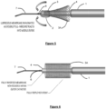
- the ring 8 pulls the lubricous elastic membrane 2 connected it behind it, allowing the lubricous elastic membrane 2 to invaginate into the space between the inner catheter 2 and the outer catheter 4.
- the lubricous elastic membrane 2 is pulled back from over the crimped stent 3, from the proximal edge to the distal edge, allowing the stent 3 to expand from the proximal edge and fixing the proximal edge accurately in place within the lumen.
- Fig. 6 is a diagrammatic view 600, showing the fully expanded stent 3 in place in the lumen.
- the lubricous elastic membrane (not shown) is pulled back into the space between the inner catheter 2 and outer catheter 4.
- the removal of the lubricous elastic membrane 2 from over the stent 3 releases both the proximal and distal end of the stent 3, in that order.
- the release allows the stent 3 to expand from its crimped state to its expanded state 3A in a proximal-to-distal fashion.
- Fig. 9 is a cross-sectional view 900 of the stent deployment device after the stent 3 has been deployed in a proximal-to-distal fashion.
- the stent is shown in a fully expanded state 3A after deployment, and the inverted and invaginated lubricous elastic membrane 2A is shown in the inter space between the inner catheter 6 and the outer catheter 4.
- Fig. 7 is a diagrammatic view of the released and deployed stent 3A with the outer catheter 4 withdrawn into the sheath catheter as a first step in full deployment of the stent in the lumen and removal of the deployment device.
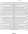
- FIG. 10 A method 1000 for deploying a stent in a proximal-to-distal manner, not according to the claimed invention, is shown in Fig. 10 . It will be appreciated that the method 1000 may include additional or fewer steps than that shown in Fig. 10 .
- a small opening or slit is made in the groin region of the patient to gain access to the femoral artery then a guide wire is inserted into the femoral artery (block S1001).
- the tip of the guide wire is advanced to the location where the stent is to be deployed and the guide wire is anchored in place (block S1002).
- the guide wire may have a region which is visible in an X-ray scanner, such that the guide wire is delivered to the location under guidance from X-ray imaging, as known to those of skill in the art.
- the stent deployment device is guided over the guide wire to the correct location for stent insertion within the body lumen (block S1003).
- the stent deployment device may also be delivered to the location under X-Ray imaging guidance.
- the outer catheter is slid out from within the sheath catheter to expose the crimped stent covered by the elastic-lubricous-membrane (block S1004).
- the outer sheath catheter itself is not a requirement for the stent deployment but is used typically to provide protection to the elastic-lubricous-membrane covering the stent in the new deployment device. In an embodiment that does not include a sheath catheter, this step may be skipped.
- the method 1000 continues by aligning the proximal edge of the crimped stent to the exact location (block S1005). It will be appreciated that alignment may performed using x-ray imaging or other known stent delivery visualization techniques.
- the method 1000 continues by applying a uniform pull to the ring on the elastic lubricous membrane using a pull mechanism (S1006).
- the pulling mechanism is connected to the pull wires at the proximal end of the sheath catheter and is connected to the ring, which is in turn attached to the distal end of the elastic lubricous membrane.
- the pull applied to the ring using the pull wires pulls the ring and the elastic lubricous membrane into the space between the inner catheter and the outer catheter (block S1007).
- the pull applied to the elastic lubricous membrane releases the cover of the crimped stent from its proximal end, allowing its expansion and deployment from the proximal-to-distal end with the proximal end accurately aligned to the proximal end placement location of the stent within the body lumen (block S1008).
- the elastic lubricous membrane is completely inverted and invaginated into the space between the inner catheter and outer catheter behind the connected ring (block S1009).
- the outer catheter and the inner catheter are pulled back into the sheath catheter and the stent deployment device is removed, leaving the stent accurately deployed in place within the body lumen (block S1010).
- the anchoring of the guide wire is removed and the guide wire is withdrawn and the incision closed securely completing the procedure (block S1001).
- the stent is left accurately deployed in the body lumen, thereby completing the procedure.
Landscapes
- Health & Medical Sciences (AREA)
- Engineering & Computer Science (AREA)
- Biomedical Technology (AREA)
- Cardiology (AREA)
- Oral & Maxillofacial Surgery (AREA)
- Transplantation (AREA)
- Heart & Thoracic Surgery (AREA)
- Vascular Medicine (AREA)
- Life Sciences & Earth Sciences (AREA)
- Animal Behavior & Ethology (AREA)
- General Health & Medical Sciences (AREA)
- Public Health (AREA)
- Veterinary Medicine (AREA)
- Media Introduction/Drainage Providing Device (AREA)
Claims (5)
- Stenteinführungssystem (100), Folgendes umfassend:einen Führungsdraht (7);einen inneren Katheter (6);einen äußeren Katheter (4);einen expandierbaren Stent (3);eine elastische Membran (2), die den expandierbaren Stent (3) entnehmbar abdeckt, wobei die elastische Membran (2) ein proximales Ende und ein distales Ende aufweist;wobei der innere Katheter (6) gleitend über den Führungsdraht (7) bewegbar ist;wobei der äußere Katheter (4) gleitend über den inneren Katheter (6) bewegbar ist, sodass ein Zwischenraum zwischen dem inneren Katheter (6) und dem äußeren Katheter (4) gebildet wird;
dadurch gekennzeichnet, dassder expandierbare Stent (3) auf den äußeren Katheter (4) gecrimpt ist;die elastische Membran (2) eine elastische schlüpfrige Membran (2) ist;ein Ring (8) gleitend über den inneren Katheter (6) eingeführt und in den Zwischenraum zurückziehbar ist, wobei der Ring (8) an dem distalen Ende der elastischen schlüpfrigen Membran (2) befestigt ist; undeine Vielzahl von Zugdrähten (5) mit dem Ring (8) verbunden sind, um den Ring (8) und die elastische schlüpfrige Membran (2) in den Zwischenraum zurückzuziehen. - System nach Anspruch 1, ferner umfassend einen Hüllkatheter (1), wobei der äußere Katheter (4) gleitend innerhalb des Hüllkatheters (1) bewegbar ist.
- System nach Anspruch 1, wobei die Vielzahl von Zugdrähten (5) zwei Zugdrähte umfasst.
- System nach Anspruch 1, ferner umfassend einen Zugmechanismus, der mit dem proximalen Ende der Zugdrähte (5) verbunden ist und zum Aufbringen einer Rückzugskraft dient, um den Ring (8) und die elastische schlüpfrige Membran (2) in den Zwischenraum zurückzuziehen.
- System nach Anspruch 1, wobei die elastische schlüpfrige Membran (2) umstülpbar ist.
Applications Claiming Priority (2)
| Application Number | Priority Date | Filing Date | Title |
|---|---|---|---|
| US14/683,101 US9636244B2 (en) | 2015-04-09 | 2015-04-09 | Apparatus and method for proximal to distal stent deployment |
| PCT/US2016/024794 WO2016164215A1 (en) | 2015-04-09 | 2016-03-29 | Apparatus and method for proximal to distal stent deployment |
Publications (3)
| Publication Number | Publication Date |
|---|---|
| EP3280355A1 EP3280355A1 (de) | 2018-02-14 |
| EP3280355A4 EP3280355A4 (de) | 2019-03-13 |
| EP3280355B1 true EP3280355B1 (de) | 2024-07-17 |
Family
ID=57072166
Family Applications (1)
| Application Number | Title | Priority Date | Filing Date |
|---|---|---|---|
| EP16777055.1A Active EP3280355B1 (de) | 2015-04-09 | 2016-03-29 | Vorrichtung für proximale-zu-distale-stenteinführung |
Country Status (3)
| Country | Link |
|---|---|
| US (2) | US9636244B2 (de) |
| EP (1) | EP3280355B1 (de) |
| WO (1) | WO2016164215A1 (de) |
Families Citing this family (33)
| Publication number | Priority date | Publication date | Assignee | Title |
|---|---|---|---|---|
| US10213187B1 (en) | 2012-01-25 | 2019-02-26 | Mubin I. Syed | Method and apparatus for percutaneous superficial temporal artery access for carotid artery stenting |
| WO2014081947A1 (en) | 2012-11-21 | 2014-05-30 | Syed Mubin I | System for the intravascular placement of a medical device |
| US9636244B2 (en) | 2015-04-09 | 2017-05-02 | Mubin I. Syed | Apparatus and method for proximal to distal stent deployment |
| US10602983B2 (en) | 2015-05-08 | 2020-03-31 | St. Jude Medical International Holding S.À R.L. | Integrated sensors for medical devices and method of making integrated sensors for medical devices |
| CN111657866B (zh) | 2015-10-21 | 2023-10-20 | 圣犹达医疗用品心脏病学部门有限公司 | 高密度电极标测导管 |
| CN114668490B (zh) | 2015-10-21 | 2025-10-03 | 圣犹达医疗用品心脏病学部门有限公司 | 高密度电极标测导管 |
| US10327929B2 (en) | 2015-10-30 | 2019-06-25 | Ram Medical Innovations, Llc | Apparatus and method for stabilization of procedural catheter in tortuous vessels |
| US9980838B2 (en) | 2015-10-30 | 2018-05-29 | Ram Medical Innovations Llc | Apparatus and method for a bifurcated catheter for use in hostile aortic arches |
| US10779976B2 (en) | 2015-10-30 | 2020-09-22 | Ram Medical Innovations, Llc | Apparatus and method for stabilization of procedural catheter in tortuous vessels |
| US11020256B2 (en) | 2015-10-30 | 2021-06-01 | Ram Medical Innovations, Inc. | Bifurcated “Y” anchor support for coronary interventions |
| US10492936B2 (en) | 2015-10-30 | 2019-12-03 | Ram Medical Innovations, Llc | Apparatus and method for improved access of procedural catheter in tortuous vessels |
| CN109310469B (zh) | 2016-05-03 | 2021-07-23 | 圣犹达医疗用品心脏病学部门有限公司 | 冲洗高密度电极导管 |
| US10173031B2 (en) | 2016-06-20 | 2019-01-08 | Mubin I. Syed | Interchangeable flush/selective catheter |
| US11786705B2 (en) | 2016-10-24 | 2023-10-17 | St. Jude Medical, Cardiology Division, Inc. | Catheter insertion devices |
| US11172858B2 (en) | 2016-10-28 | 2021-11-16 | St. Jude Medical, Cardiology Division, Inc. | Flexible high-density mapping catheter |
| JP7329442B2 (ja) | 2017-01-19 | 2023-08-18 | セント・ジュード・メディカル,カーディオロジー・ディヴィジョン,インコーポレイテッド | シースの可視化 |
| EP3606420B1 (de) | 2017-07-07 | 2023-05-24 | St. Jude Medical, Cardiology Division, Inc. | Geschichteter hochdichter elektrodenabbildungskatheter |
| US11647935B2 (en) | 2017-07-24 | 2023-05-16 | St. Jude Medical, Cardiology Division, Inc. | Masked ring electrodes |
| EP4241819B1 (de) | 2017-11-28 | 2026-02-25 | St. Jude Medical, Cardiology Division, Inc. | Steuerbarer expandierbarer katheter |
| US10857014B2 (en) | 2018-02-18 | 2020-12-08 | Ram Medical Innovations, Llc | Modified fixed flat wire bifurcated catheter and its application in lower extremity interventions |
| CN117958829A (zh) | 2018-03-13 | 2024-05-03 | 圣犹达医疗用品心脏病学部门有限公司 | 可变密度标测导管 |
| WO2019195439A1 (en) | 2018-04-05 | 2019-10-10 | St. Jude Medical, Cardiology Division, Inc. | High density electrode mapping catheter |
| US12156979B2 (en) | 2018-05-21 | 2024-12-03 | St. Jude Medical, Cardiology Division, Inc. | Deflectable catheter shaft with pullwire anchor feature |
| JP7499702B2 (ja) | 2018-05-21 | 2024-06-14 | セント・ジュード・メディカル,カーディオロジー・ディヴィジョン,インコーポレイテッド | 高周波アブレーション及び直流電気穿孔カテーテル |
| WO2020039392A2 (en) | 2018-08-23 | 2020-02-27 | St. Jude Medical, Cardiology Division, Inc. | Curved high density electrode mapping catheter |
| WO2020065587A2 (en) | 2018-09-27 | 2020-04-02 | St. Jude Medical, Cardiology Division, Inc. | Uniform mapping balloon |
| US11918762B2 (en) | 2018-10-03 | 2024-03-05 | St. Jude Medical, Cardiology Division, Inc. | Reduced actuation force electrophysiology catheter handle |
| WO2020126001A1 (de) * | 2018-12-20 | 2020-06-25 | Medizinische Universität Wien | Stentgraft und vorrichtung zum zuführen und setzen eines solchen stentgrafts in die aorta ascendens |
| CN113271898B (zh) | 2019-01-09 | 2025-01-21 | 波士顿科学国际有限公司 | 支架输送系统 |
| CN115942915B (zh) | 2020-08-18 | 2025-11-28 | 圣犹达医疗用品心脏病学部门有限公司 | 具有磁性位置跟踪的高密度电极导管 |
| WO2023281599A1 (ja) * | 2021-07-05 | 2023-01-12 | 日本ライフライン株式会社 | 治療装置 |
| CN114073612B (zh) * | 2021-11-22 | 2024-07-16 | 衢州市人民医院 | 一种可精准定位的支架输送系统 |
| US12551658B2 (en) | 2022-03-25 | 2026-02-17 | St. Jude Medical, Cardiology Division, Inc. | Steerable introducer with slide block divider |
Family Cites Families (170)
| Publication number | Priority date | Publication date | Assignee | Title |
|---|---|---|---|---|
| US4243040A (en) * | 1979-09-17 | 1981-01-06 | Beecher William H | Extracting device for removing objects from human body passages |
| US4790331A (en) | 1986-12-02 | 1988-12-13 | Sherwood Medical Company | Method for placement of catheter in a blood vessel |
| US5098707A (en) | 1989-07-31 | 1992-03-24 | Merck & Co., Inc. | Imidazole compounds and their use as transglutaminase inhibitors |
| US5344426A (en) * | 1990-04-25 | 1994-09-06 | Advanced Cardiovascular Systems, Inc. | Method and system for stent delivery |
| US6808520B1 (en) | 1991-12-13 | 2004-10-26 | Endovascular Technologies, Inc. | Dual valve, flexible expandable sheath and method |
| US5293772A (en) | 1992-01-17 | 1994-03-15 | Center For Innovative Technology | Instrumentation and method for evaluating platelet performance during clotting and dissolution of blood clots and for evaluating erythrocyte flexibility |
| US5514131A (en) | 1992-08-12 | 1996-05-07 | Stuart D. Edwards | Method for the ablation treatment of the uvula |
| JPH08500757A (ja) * | 1992-12-30 | 1996-01-30 | シュナイダー・(ユーエスエイ)・インコーポレーテッド | 身体に移植可能なステントを展開する装置 |
| US5571135A (en) * | 1993-10-22 | 1996-11-05 | Scimed Life Systems Inc. | Stent delivery apparatus and method |
| DE4408108A1 (de) | 1994-03-10 | 1995-09-14 | Bavaria Med Tech | Katheter zur Injektion eines Fluid bzw. eines Arneimittelns |
| US6152141A (en) | 1994-07-28 | 2000-11-28 | Heartport, Inc. | Method for delivery of therapeutic agents to the heart |
| US5606975A (en) | 1994-09-19 | 1997-03-04 | The Board Of Trustees Of The Leland Stanford Junior University | Forward viewing ultrasonic imaging catheter |
| AU4632196A (en) * | 1995-04-14 | 1996-10-30 | Schneider (Usa) Inc. | Rolling membrane stent delivery device |
| WO1996036269A2 (en) | 1995-05-09 | 1996-11-21 | Edoga John K | Methods and apparatus for treating abdominal aortic aneurysms |
| US6375615B1 (en) | 1995-10-13 | 2002-04-23 | Transvascular, Inc. | Tissue penetrating catheters having integral imaging transducers and their methods of use |
| US5766192A (en) | 1995-10-20 | 1998-06-16 | Zacca; Nadim M. | Atherectomy, angioplasty and stent method and apparatus |
| US5669924A (en) | 1995-10-26 | 1997-09-23 | Shaknovich; Alexander | Y-shuttle stent assembly for bifurcating vessels and method of using the same |
| US5813976A (en) | 1996-04-02 | 1998-09-29 | Filipi; Charles J. | Stabilizing instrumentation for the performing of endoscopic surgical procedures |
| US6379319B1 (en) | 1996-10-11 | 2002-04-30 | Transvascular, Inc. | Systems and methods for directing and snaring guidewires |
| US6599316B2 (en) | 1996-11-04 | 2003-07-29 | Advanced Stent Technologies, Inc. | Extendible stent apparatus |
| US5807330A (en) | 1996-12-16 | 1998-09-15 | University Of Southern California | Angioplasty catheter |
| US5720735A (en) | 1997-02-12 | 1998-02-24 | Dorros; Gerald | Bifurcated endovascular catheter |
| US6026814A (en) | 1997-03-06 | 2000-02-22 | Scimed Life Systems, Inc. | System and method for percutaneous coronary artery bypass |
| US6070589A (en) | 1997-08-01 | 2000-06-06 | Teramed, Inc. | Methods for deploying bypass graft stents |
| US6361544B1 (en) | 1997-08-13 | 2002-03-26 | Advanced Cardiovascular Systems, Inc. | Stent and catheter assembly and method for treating bifurcations |
| US5957901A (en) | 1997-10-14 | 1999-09-28 | Merit Medical Systems, Inc. | Catheter with improved spray pattern for pharmaco-mechanical thrombolysis therapy |
| US20100030256A1 (en) | 1997-11-12 | 2010-02-04 | Genesis Technologies Llc | Medical Devices and Methods |
| AU4318499A (en) | 1997-11-24 | 1999-12-13 | Burdette Medical Systems, Inc. | Real time brachytherapy spatial registration and visualization system |
| US6245573B1 (en) | 1998-02-12 | 2001-06-12 | University Of Medicine And Dentistry Of New Jersey | Rapid assessment of the coagulant activity of blood |
| US6027462A (en) | 1998-07-30 | 2000-02-22 | Medtronic, Inc. | Method and apparatus for deflecting a screw-in-lead |
| US6117117A (en) | 1998-08-24 | 2000-09-12 | Advanced Cardiovascular Systems, Inc. | Bifurcated catheter assembly |
| US5997563A (en) | 1998-09-28 | 1999-12-07 | Medtronic, Inc. | Implantable stent having variable diameter |
| US6245017B1 (en) | 1998-10-30 | 2001-06-12 | Kabushiki Kaisha Toshiba | 3D ultrasonic diagnostic apparatus |
| US6059813A (en) * | 1998-11-06 | 2000-05-09 | Scimed Life Systems, Inc. | Rolling membrane stent delivery system |
| US6544278B1 (en) * | 1998-11-06 | 2003-04-08 | Scimed Life Systems, Inc. | Rolling membrane stent delivery system |
| DE29822381U1 (de) | 1998-12-16 | 1999-03-18 | Fumedica Intertrade AG, Hünenberg | Vorrichtung zum Einsetzen einer Aorten-Endoprothese |
| US10327743B2 (en) | 1999-04-09 | 2019-06-25 | Evalve, Inc. | Device and methods for endoscopic annuloplasty |
| EP1225935A4 (de) | 1999-10-12 | 2009-07-29 | Allan R Will | Verfahren und vorrichtung zum schutz eines zugangs in den körper |
| US6383171B1 (en) | 1999-10-12 | 2002-05-07 | Allan Will | Methods and devices for protecting a passageway in a body when advancing devices through the passageway |
| US8092509B2 (en) | 1999-11-11 | 2012-01-10 | Angiomed Gmbh & Co. Medizintechnik Kg | Implant delivery device |
| US7758624B2 (en) | 2000-11-13 | 2010-07-20 | C. R. Bard, Inc. | Implant delivery device |
| US6254593B1 (en) | 1999-12-10 | 2001-07-03 | Advanced Cardiovascular Systems, Inc. | Bifurcated stent delivery system having retractable sheath |
| US6663613B1 (en) | 2000-01-25 | 2003-12-16 | Bacchus Vascular, Inc. | System and methods for clot dissolution |
| US6929633B2 (en) | 2000-01-25 | 2005-08-16 | Bacchus Vascular, Inc. | Apparatus and methods for clot dissolution |
| DE60134739D1 (de) | 2000-05-16 | 2008-08-21 | Atrionix Inc | Katheter mit lenkbarer spitze und spurausrichtungsmechanismus eines führungsdrahts |
| US6464665B1 (en) | 2000-07-05 | 2002-10-15 | Richard R. Heuser | Catheter apparatus and method for arterializing a vein |
| US6450964B1 (en) | 2000-09-05 | 2002-09-17 | Advanced Cardiovascular Systems, Inc. | Imaging apparatus and method |
| US20050222489A1 (en) | 2003-10-01 | 2005-10-06 | Ample Medical, Inc. | Devices, systems, and methods for reshaping a heart valve annulus, including the use of a bridge implant |
| US20020077691A1 (en) * | 2000-12-18 | 2002-06-20 | Advanced Cardiovascular Systems, Inc. | Ostial stent and method for deploying same |
| DE60222870T2 (de) | 2001-02-06 | 2008-05-15 | Medtronic Vascular, Inc., Santa Rosa | Vorrichtung für transluminale eingriffe mit geführten kathetern oder anderen geräten, die die gefässwande durchdringen |
| US6595980B1 (en) | 2001-02-23 | 2003-07-22 | Coaxia, Inc. | Devices and methods for preventing distal embolization using flow reversal by occlusion of the brachiocephalic artery |
| WO2002076346A1 (en) | 2001-03-23 | 2002-10-03 | Hassan Tehrani | Branched aortic arch stent graft |
| US20040138734A1 (en) | 2001-04-11 | 2004-07-15 | Trivascular, Inc. | Delivery system and method for bifurcated graft |
| US6764505B1 (en) | 2001-04-12 | 2004-07-20 | Advanced Cardiovascular Systems, Inc. | Variable surface area stent |
| US20030013986A1 (en) | 2001-07-12 | 2003-01-16 | Vahid Saadat | Device for sensing temperature profile of a hollow body organ |
| US20100016943A1 (en) | 2001-12-20 | 2010-01-21 | Trivascular2, Inc. | Method of delivering advanced endovascular graft |
| EP1465701A4 (de) | 2002-01-15 | 2008-08-13 | Univ California | System und verfahren zur direktionalen ultraschalltherapie an gelenkigen verbindungen |
| US6932829B2 (en) | 2002-06-24 | 2005-08-23 | Cordis Corporation | Centering catheter |
| US7314484B2 (en) | 2002-07-02 | 2008-01-01 | The Foundry, Inc. | Methods and devices for treating aneurysms |
| US8613744B2 (en) | 2002-09-30 | 2013-12-24 | Relievant Medsystems, Inc. | Systems and methods for navigating an instrument through bone |
| EP1608293B1 (de) | 2003-04-03 | 2015-06-03 | Cook Medical Technologies LLC | Einführsystem für einen verzweigten stent-graft |
| EP1635736A2 (de) | 2003-06-05 | 2006-03-22 | FlowMedica, Inc. | Systeme und verfahren zur durchführung von bilateralen interventionen oder diagnose in verzweigten körperlumen |
| US7235083B1 (en) | 2003-09-10 | 2007-06-26 | Endovascular Technologies, Inc. | Methods and devices for aiding in situ assembly of repair devices |
| US7794398B2 (en) | 2003-09-29 | 2010-09-14 | Koninklijke Philips Electronics N.V. | Real-time volumetric bi-plane ultrasound imaging and quantification |
| WO2005037141A2 (en) | 2003-10-14 | 2005-04-28 | William A. Cook Australia Pty. Ltd. | Introducer for an iliac side branch device |
| EP1684842B1 (de) | 2003-10-27 | 2013-03-06 | Petrus Antonius Besselink | Selbstaktivierende endoluminale vorrichtung |
| US20050101968A1 (en) | 2003-11-12 | 2005-05-12 | Dadourian Daniel G. | Ostial locator device and methods for transluminal interventions |
| US7361180B2 (en) | 2004-05-07 | 2008-04-22 | Usgi Medical, Inc. | Apparatus for manipulating and securing tissue |
| US20050234499A1 (en) | 2004-04-19 | 2005-10-20 | Scimed Life Systems, Inc. | Multi-lumen balloon catheter including manifold |
| US8623067B2 (en) | 2004-05-25 | 2014-01-07 | Covidien Lp | Methods and apparatus for luminal stenting |
| ATE390096T1 (de) * | 2004-07-28 | 2008-04-15 | Cordis Corp | Einführvorrichtung mit einer niedrigen entfaltungskraft |
| WO2006015091A2 (en) | 2004-07-28 | 2006-02-09 | University Of Virginia Patent Foundation | Coaxial catheter systems for transference of medium |
| US7955370B2 (en) * | 2004-08-06 | 2011-06-07 | Boston Scientific Scimed, Inc. | Stent delivery system |
| US7393358B2 (en) * | 2004-08-17 | 2008-07-01 | Boston Scientific Scimed, Inc. | Stent delivery system |
| US7402151B2 (en) | 2004-12-17 | 2008-07-22 | Biocardia, Inc. | Steerable guide catheters and methods for their use |
| US8287583B2 (en) | 2005-01-10 | 2012-10-16 | Taheri Laduca Llc | Apparatus and method for deploying an implantable device within the body |
| US7632296B2 (en) * | 2005-03-03 | 2009-12-15 | Boston Scientific Scimed, Inc. | Rolling membrane with hydraulic recapture means for self expanding stent |
| US7828832B2 (en) | 2005-04-18 | 2010-11-09 | Medtronic Vascular, Inc. | Intravascular deployment device with improved deployment capability |
| US20060259063A1 (en) | 2005-04-25 | 2006-11-16 | Bates Brian L | Wire guides having distal anchoring devices |
| US7465434B2 (en) | 2005-04-25 | 2008-12-16 | Jacob Benford | Diagnosis of blood clots using fibrin-binding proteins bound with contrast agents |
| US8936577B2 (en) | 2005-05-02 | 2015-01-20 | Shi Zi Technology, Ltd. | Methods and devices for autoflush syringes |
| EP1902331B1 (de) | 2005-05-04 | 2012-07-11 | Volcano Corporation | Miniatur-stellgliedmechanismus für die intravaskuläre bildgebung |
| FR2885794B1 (fr) * | 2005-05-19 | 2007-08-17 | Perouse Soc Par Actions Simpli | Necessaire de largage d'un organe de traitement d'une cavite et procede de preparation d'un organe de traitement associe |
| US20060270900A1 (en) | 2005-05-26 | 2006-11-30 | Chin Albert K | Apparatus and methods for performing ablation |
| US8932208B2 (en) | 2005-05-26 | 2015-01-13 | Maquet Cardiovascular Llc | Apparatus and methods for performing minimally-invasive surgical procedures |
| WO2007002685A2 (en) | 2005-06-24 | 2007-01-04 | Volcano Corporation | Co-registration of graphical image data representing three-dimensional vascular features |
| US20070043389A1 (en) | 2005-08-05 | 2007-02-22 | Shintech, Llc | System for treating chronic total occlusion caused by lower extremity arterial disease |
| AU2006284540A1 (en) | 2005-08-25 | 2007-03-01 | Osprey Medical Inc. | Devices and methods for perfusing an organ |
| US20070083215A1 (en) | 2005-10-07 | 2007-04-12 | Hamer Rochelle M | Conduit for interventional procedures |
| US20070118151A1 (en) | 2005-11-21 | 2007-05-24 | The Brigham And Women's Hospital, Inc. | Percutaneous cardiac valve repair with adjustable artificial chordae |
| DE102005062731A1 (de) | 2005-12-22 | 2007-06-28 | Organobalance Gmbh | Neue Lactobacillus Stämme und deren Verwendung |
| US8728144B2 (en) | 2005-12-29 | 2014-05-20 | Cook Medical Technologies Llc | Endoluminal device including a mechanism for proximal or distal fixation, and sealing and methods of use thereof |
| EP1973594A1 (de) | 2005-12-29 | 2008-10-01 | NMT Medical, Inc. | Mit einer spritze aktiviertes ventil zum durchspülen eines katheters und verfahren dafür |
| US20070208302A1 (en) | 2006-01-26 | 2007-09-06 | Webster Mark W | Deflection control catheters, support catheters and methods of use |
| US8235916B2 (en) | 2006-02-03 | 2012-08-07 | Pacesetter, Inc. | System and method for manipulating insertion pathways for accessing target sites |
| US20080039746A1 (en) | 2006-05-25 | 2008-02-14 | Medtronic, Inc. | Methods of using high intensity focused ultrasound to form an ablated tissue area containing a plurality of lesions |
| US7651520B2 (en) | 2006-05-30 | 2010-01-26 | Ostial Solutions, Llc | Means and method for the accurate placement of a stent at the ostium of an artery |
| US7740791B2 (en) | 2006-06-30 | 2010-06-22 | Advanced Cardiovascular Systems, Inc. | Method of fabricating a stent with features by blow molding |
| US8740971B2 (en) | 2006-07-11 | 2014-06-03 | Gabriele Iannelli | Vascular prosthesis |
| US8038622B2 (en) | 2007-08-03 | 2011-10-18 | Innoscion, Llc | Wired and wireless remotely controlled ultrasonic transducer and imaging apparatus |
| WO2008054395A1 (en) | 2006-11-03 | 2008-05-08 | Research Triangle Institute | Enhanced ultrasound imaging probes using flexure mode piezoelectric transducers |
| US8079263B2 (en) | 2006-11-10 | 2011-12-20 | Penrith Corporation | Transducer array imaging system |
| US20080194993A1 (en) | 2006-11-15 | 2008-08-14 | Mclaren Douglas E | Multi-dimensional loop tip elongated medical structures |
| US8821567B2 (en) | 2007-02-22 | 2014-09-02 | Mohsin Saeed | Apparatus and method for implantation of a bifurcated endovascular prosthesis |
| US8343181B2 (en) | 2007-03-01 | 2013-01-01 | Medtronic Vascular, Inc. | Method and apparatus for treating stenoses at bifurcated regions |
| US8764816B2 (en) * | 2007-05-07 | 2014-07-01 | W. L. Gore & Associates, Inc. | Stent delivery and deployment system |
| US8057394B2 (en) | 2007-06-30 | 2011-11-15 | St. Jude Medical, Atrial Fibrillation Division, Inc. | Ultrasound image processing to render three-dimensional images from two-dimensional images |
| WO2009052367A1 (en) | 2007-10-17 | 2009-04-23 | Clemson University | Micro- and nanoscale devices for delivery of active fibronolytic agents |
| US20090132019A1 (en) | 2007-11-15 | 2009-05-21 | Medtronic Vascular, Inc. | Bifurcate Stent Delivery Catheter |
| EP2067443B1 (de) | 2007-12-07 | 2011-02-23 | Wright Medical Technology, Inc. | Nadelzentrierführung mit Winkelmesser |
| US20090171293A1 (en) | 2007-12-28 | 2009-07-02 | Wilson-Cook Medical Inc. | Self expanding wire guide |
| US20090177035A1 (en) | 2008-01-03 | 2009-07-09 | Chin Albert K | Endoscope instruments systems and methods for closed chest epicardial ablation |
| WO2009105231A1 (en) | 2008-02-20 | 2009-08-27 | The General Hospital Corporation | Compositions and methods for treating vascular disorders |
| CN102056574B (zh) | 2008-04-03 | 2014-07-16 | 加尔迪亚医疗有限公司 | 回收配置的医疗设备的回收导管和方法 |
| AU2009276568B2 (en) | 2008-07-29 | 2015-04-23 | Carefusion 207, Inc. | Valve assembly for respiratory systems |
| JP5317566B2 (ja) | 2008-07-30 | 2013-10-16 | テルモ株式会社 | カテーテル組立体 |
| US8721714B2 (en) * | 2008-09-17 | 2014-05-13 | Medtronic Corevalve Llc | Delivery system for deployment of medical devices |
| US8372108B2 (en) | 2009-01-16 | 2013-02-12 | Claret Medical, Inc. | Intravascular blood filter |
| US8690776B2 (en) | 2009-02-17 | 2014-04-08 | Inneroptic Technology, Inc. | Systems, methods, apparatuses, and computer-readable media for image guided surgery |
| CN102395400B (zh) | 2009-04-14 | 2014-12-03 | 泰尔茂株式会社 | 医用导丝 |
| CN102438551A (zh) | 2009-05-08 | 2012-05-02 | 皇家飞利浦电子股份有限公司 | 可植入医疗装置的超声规划和引导 |
| IES20100331A2 (en) | 2009-05-22 | 2011-01-05 | Ulbrich Prec Metals Ltd | An angioplasty assembly |
| US20110009943A1 (en) * | 2009-07-09 | 2011-01-13 | Paul Ram H | Delivery system with medical device release by evertable sleeve |
| EP2456369B1 (de) | 2009-07-21 | 2018-10-24 | University Of Virginia Patent Foundation | Systeme zur ultraschall-abbildung und ableitung von mikroblasen |
| US20110034987A1 (en) * | 2009-08-04 | 2011-02-10 | Kennedy Kenneth C | Roll sleeve mechanism for proximal release stent |
| US8277417B2 (en) | 2009-09-23 | 2012-10-02 | James J. Fedinec | Central venous catheter kit with line gripping and needle localizing devices |
| US9180275B2 (en) | 2011-01-31 | 2015-11-10 | Robert E. Helm | Catheter-dressing systems with integrated flushing mechanisms |
| US8496607B2 (en) | 2009-12-04 | 2013-07-30 | Cook Medical Technologies Llc | Multi-lumen catheter |
| BR112012019354B1 (pt) | 2010-02-02 | 2021-09-08 | C.R.Bard, Inc | Método para localização de um dispositivo médico implantável |
| US20100204708A1 (en) | 2010-02-23 | 2010-08-12 | Sanjiv Sharma | Carotid guiding catheter (sheath) for carotid percutaneous intervention/stenting with internal fixation device to prevent migration of the Carotid guiding catheter (sheath) |
| WO2011106502A2 (en) | 2010-02-25 | 2011-09-01 | Mayo Foundation For Medical Education And Research | Delivering drugs to desired locations within a mammal |
| US8545552B2 (en) | 2010-02-26 | 2013-10-01 | Silk Road Medical, Inc. | Systems and methods for transcatheter aortic valve treatment |
| US20130190726A1 (en) | 2010-04-30 | 2013-07-25 | Children's Medical Center Corporation | Motion compensating catheter device |
| US8419767B2 (en) | 2010-05-04 | 2013-04-16 | Mustafa H. Al-Qbandi | Steerable atrial septal occluder implantation device with flexible neck |
| US20120027687A1 (en) | 2010-07-08 | 2012-02-02 | Alkon Daniel L | Fatty acid protein kinase c activators and anticoagulant for the treatment of stroke |
| US9504802B2 (en) | 2010-07-19 | 2016-11-29 | Sukhjit Gill | Guiding catheter stabilization system |
| KR101117524B1 (ko) | 2010-09-03 | 2012-03-20 | 신경민 | 스텐트 시술용 카데터 |
| JP2013544133A (ja) | 2010-10-25 | 2013-12-12 | メドトロニック アーディアン ルクセンブルク ソシエテ ア レスポンサビリテ リミテ | 腎ニューロモジュレーションのためのマルチ電極アレイを有するカテーテル装置ならびに関連のシステムおよび方法 |
| JP2013541392A (ja) | 2010-11-08 | 2013-11-14 | コリブリ テクノロジーズ インコーポレーテッド | 低侵襲処置の間の改善された視覚化のためのシステム及び方法 |
| US9218687B2 (en) | 2010-12-30 | 2015-12-22 | St. Jude Medical, Atrial Fibrillation Division, Inc. | Display of medical device position information in a volumetric rendering |
| US20120209375A1 (en) | 2011-02-11 | 2012-08-16 | Gilbert Madrid | Stability device for use with percutaneous delivery systems |
| WO2012154277A1 (en) | 2011-02-25 | 2012-11-15 | C.R. Bard, Inc. | Medical component insertion device including a retractable needle |
| US9301830B2 (en) | 2011-03-17 | 2016-04-05 | Pq Bypass, Inc. | Differential dilation stent and method of use |
| US20120290063A1 (en) | 2011-05-09 | 2012-11-15 | Abbott Cardiovascular Systems Inc. | Method of Increasing Stent Retention of Bioabsorbable Scaffolding with a Sheath |
| US9039713B2 (en) | 2011-05-13 | 2015-05-26 | Merit Medical Systems, Inc. | Releasably attached snare loop retrieval device and method of using the same |
| US20130053792A1 (en) | 2011-08-24 | 2013-02-28 | Ablative Solutions, Inc. | Expandable catheter system for vessel wall injection and muscle and nerve fiber ablation |
| AU2012315597B2 (en) | 2011-09-30 | 2016-01-07 | Bioventrix, Inc. | Trans-catheter ventricular reconstruction structures, methods, and systems for treatment of congestive heart failure and other conditions |
| US20150201900A1 (en) | 2012-01-25 | 2015-07-23 | Mubin I. Syed | Multi-pane imaging transducer associated with a guidewire |
| US20130331921A1 (en) | 2012-06-08 | 2013-12-12 | Gary Roubin | Bifurcated catheter |
| US9066793B2 (en) | 2012-11-12 | 2015-06-30 | Yen-Ni Hung | Method of implanting an aortic stent |
| US20140142427A1 (en) | 2012-11-16 | 2014-05-22 | Lightlab Imaging, Inc. | Automated Fluid Delivery Catheter and System |
| WO2014081947A1 (en) | 2012-11-21 | 2014-05-30 | Syed Mubin I | System for the intravascular placement of a medical device |
| US20140214002A1 (en) | 2013-01-27 | 2014-07-31 | Thermopeutix, Inc. | Bifurcation catheter with variable length occlusion elements |
| US9888993B2 (en) | 2013-03-01 | 2018-02-13 | St. Jude Medical, Cardiology Division, Inc. | Embolic protection device |
| CA3124754C (en) | 2013-03-15 | 2023-08-15 | Children's Medical Center Corporation | Shunt flusher |
| US10322260B2 (en) | 2013-05-30 | 2019-06-18 | Terumo Kabushiki Kaisha | Treatment method for treating lower limbs using multi-member catheter assembly |
| US9463104B2 (en) | 2013-06-07 | 2016-10-11 | Cedars-Sinai Medical Center | Vascular graft device placement methods |
| JP2017509370A (ja) | 2014-02-06 | 2017-04-06 | アキュブレイト, インコーポレイテッド | 自己誘導型切除のための装置および方法 |
| US20160120509A1 (en) | 2014-10-30 | 2016-05-05 | Mubin I. Syed | Hypodermic needle with enhanced ultrasound signature for carotid artery stenting |
| US9636244B2 (en) | 2015-04-09 | 2017-05-02 | Mubin I. Syed | Apparatus and method for proximal to distal stent deployment |
| US10492936B2 (en) | 2015-10-30 | 2019-12-03 | Ram Medical Innovations, Llc | Apparatus and method for improved access of procedural catheter in tortuous vessels |
| US10327929B2 (en) | 2015-10-30 | 2019-06-25 | Ram Medical Innovations, Llc | Apparatus and method for stabilization of procedural catheter in tortuous vessels |
| US9980838B2 (en) | 2015-10-30 | 2018-05-29 | Ram Medical Innovations Llc | Apparatus and method for a bifurcated catheter for use in hostile aortic arches |
| US11020256B2 (en) | 2015-10-30 | 2021-06-01 | Ram Medical Innovations, Inc. | Bifurcated “Y” anchor support for coronary interventions |
| US10779976B2 (en) | 2015-10-30 | 2020-09-22 | Ram Medical Innovations, Llc | Apparatus and method for stabilization of procedural catheter in tortuous vessels |
| US10053693B2 (en) | 2016-01-19 | 2018-08-21 | Mubin I. Syed | Method for controlling obesity using minimally invasive means |
| US10173031B2 (en) | 2016-06-20 | 2019-01-08 | Mubin I. Syed | Interchangeable flush/selective catheter |
| US20180059124A1 (en) | 2016-08-24 | 2018-03-01 | Mubin I. Syed | APPARATUS AND METHOD FOR EARLY IDENTIFICATION OF tPA RESISTANCE FOR CLOT DISSOLUTION IN PATIENTS |
| CN108882975B (zh) | 2017-03-06 | 2022-03-15 | 拉姆医学创新股份有限公司 | 用于改善曲折血管中手术导管的接近的装置和方法 |
| WO2019070349A1 (en) | 2017-10-03 | 2019-04-11 | Ram Medical Innovations Llc | ANY YELLING ANCHOR SUPPORT FOR CORONARY INTERVENTIONS |
-
2015
- 2015-04-09 US US14/683,101 patent/US9636244B2/en active Active
-
2016
- 2016-03-29 WO PCT/US2016/024794 patent/WO2016164215A1/en not_active Ceased
- 2016-03-29 EP EP16777055.1A patent/EP3280355B1/de active Active
-
2017
- 2017-03-14 US US15/458,845 patent/US10478325B2/en active Active
Also Published As
| Publication number | Publication date |
|---|---|
| EP3280355A1 (de) | 2018-02-14 |
| EP3280355A4 (de) | 2019-03-13 |
| US10478325B2 (en) | 2019-11-19 |
| WO2016164215A1 (en) | 2016-10-13 |
| US20170181876A1 (en) | 2017-06-29 |
| US9636244B2 (en) | 2017-05-02 |
| US20160296355A1 (en) | 2016-10-13 |
Similar Documents
| Publication | Publication Date | Title |
|---|---|---|
| EP3280355B1 (de) | Vorrichtung für proximale-zu-distale-stenteinführung | |
| EP1492473B1 (de) | System zum einsetzen mehrteiliger endoluminaler vorrichtungen | |
| AU2007200651B2 (en) | Modular Stent Graft and Delivery System | |
| US8317856B2 (en) | Multi-component expandable supportive bifurcated endoluminal grafts and methods for using same | |
| JP6261339B2 (ja) | グラフトまたはグラフトシステムの配置の器具および方法 | |
| EP1014888B1 (de) | Mittel zur entfaltung einer prothese | |
| EP3210568B1 (de) | Endovaskuläre stentgraftanordnung | |
| US20080228255A1 (en) | Positionable Stent-Graft Delivery System and Method | |
| EP3903731B1 (de) | Abgabevorrichtung und system | |
| US20090264990A1 (en) | Radiopaque Imprinted Ink Marker for Stent Graft | |
| JP2014518684A (ja) | 2つの可撓性端部分を有するガイドワイヤ、およびそれを用いて分岐血管にアクセスする方法 | |
| EP2036519A1 (de) | Gabelungsstent und Stenteinbringungsanordnung | |
| US10772751B2 (en) | Fenestrated endoluminal prosthesis and system and method of deployment thereof | |
| EP3315101B1 (de) | Begrenzung einer vorgespannten abzweigdrahtschleife | |
| US20190254850A1 (en) | Systems and methods for stent delivery | |
| EP3539506A1 (de) | Vorgespannte schieberspitze für endografts | |
| GB2550938A (en) | Medical device introducer assembly particularly for branched medical devices | |
| CN113967114B (zh) | 一种主动脉快速修复支架、支架套件及递送系统 | |
| EP3040057B1 (de) | Protheseneinführungssysteme mit atraumatischer spitze zur verwendung mit auslösedrähten | |
| JP2019536524A (ja) | 接続可能なインプラントの挿入のためのドライバおよびセット | |
| HK1113653A (en) | Modular stent graft and delivery system |
Legal Events
| Date | Code | Title | Description |
|---|---|---|---|
| STAA | Information on the status of an ep patent application or granted ep patent |
Free format text: STATUS: THE INTERNATIONAL PUBLICATION HAS BEEN MADE |
|
| PUAI | Public reference made under article 153(3) epc to a published international application that has entered the european phase |
Free format text: ORIGINAL CODE: 0009012 |
|
| STAA | Information on the status of an ep patent application or granted ep patent |
Free format text: STATUS: REQUEST FOR EXAMINATION WAS MADE |
|
| 17P | Request for examination filed |
Effective date: 20171009 |
|
| AK | Designated contracting states |
Kind code of ref document: A1 Designated state(s): AL AT BE BG CH CY CZ DE DK EE ES FI FR GB GR HR HU IE IS IT LI LT LU LV MC MK MT NL NO PL PT RO RS SE SI SK SM TR |
|
| AX | Request for extension of the european patent |
Extension state: BA ME |
|
| DAV | Request for validation of the european patent (deleted) | ||
| DAX | Request for extension of the european patent (deleted) | ||
| A4 | Supplementary search report drawn up and despatched |
Effective date: 20190212 |
|
| RIC1 | Information provided on ipc code assigned before grant |
Ipc: A61F 2/962 20130101ALI20190206BHEP Ipc: A61F 2/07 20130101AFI20190206BHEP Ipc: A61F 2/844 20130101ALI20190206BHEP Ipc: A61F 2/95 20130101ALI20190206BHEP |
|
| RAP3 | Party data changed (applicant data changed or rights of an application transferred) |
Owner name: SYED, MUBIN I. |
|
| RIN1 | Information on inventor provided before grant (corrected) |
Inventor name: SYED, MUBIN I. |
|
| STAA | Information on the status of an ep patent application or granted ep patent |
Free format text: STATUS: EXAMINATION IS IN PROGRESS |
|
| 17Q | First examination report despatched |
Effective date: 20220810 |
|
| GRAP | Despatch of communication of intention to grant a patent |
Free format text: ORIGINAL CODE: EPIDOSNIGR1 |
|
| STAA | Information on the status of an ep patent application or granted ep patent |
Free format text: STATUS: GRANT OF PATENT IS INTENDED |
|
| INTG | Intention to grant announced |
Effective date: 20240320 |
|
| GRAS | Grant fee paid |
Free format text: ORIGINAL CODE: EPIDOSNIGR3 |
|
| GRAA | (expected) grant |
Free format text: ORIGINAL CODE: 0009210 |
|
| STAA | Information on the status of an ep patent application or granted ep patent |
Free format text: STATUS: THE PATENT HAS BEEN GRANTED |
|
| AK | Designated contracting states |
Kind code of ref document: B1 Designated state(s): AL AT BE BG CH CY CZ DE DK EE ES FI FR GB GR HR HU IE IS IT LI LT LU LV MC MK MT NL NO PL PT RO RS SE SI SK SM TR |
|
| REG | Reference to a national code |
Ref country code: GB Ref legal event code: FG4D |
|
| REG | Reference to a national code |
Ref country code: CH Ref legal event code: EP |
|
| REG | Reference to a national code |
Ref country code: DE Ref legal event code: R096 Ref document number: 602016088448 Country of ref document: DE |
|
| REG | Reference to a national code |
Ref country code: IE Ref legal event code: FG4D |
|
| REG | Reference to a national code |
Ref country code: LT Ref legal event code: MG9D |
|
| REG | Reference to a national code |
Ref country code: NL Ref legal event code: MP Effective date: 20240717 |
|
| PG25 | Lapsed in a contracting state [announced via postgrant information from national office to epo] |
Ref country code: PT Free format text: LAPSE BECAUSE OF FAILURE TO SUBMIT A TRANSLATION OF THE DESCRIPTION OR TO PAY THE FEE WITHIN THE PRESCRIBED TIME-LIMIT Effective date: 20241118 |
|
| REG | Reference to a national code |
Ref country code: AT Ref legal event code: MK05 Ref document number: 1703438 Country of ref document: AT Kind code of ref document: T Effective date: 20240717 |
|
| PG25 | Lapsed in a contracting state [announced via postgrant information from national office to epo] |
Ref country code: NL Free format text: LAPSE BECAUSE OF FAILURE TO SUBMIT A TRANSLATION OF THE DESCRIPTION OR TO PAY THE FEE WITHIN THE PRESCRIBED TIME-LIMIT Effective date: 20240717 |
|
| PG25 | Lapsed in a contracting state [announced via postgrant information from national office to epo] |
Ref country code: PT Free format text: LAPSE BECAUSE OF FAILURE TO SUBMIT A TRANSLATION OF THE DESCRIPTION OR TO PAY THE FEE WITHIN THE PRESCRIBED TIME-LIMIT Effective date: 20241118 Ref country code: NL Free format text: LAPSE BECAUSE OF FAILURE TO SUBMIT A TRANSLATION OF THE DESCRIPTION OR TO PAY THE FEE WITHIN THE PRESCRIBED TIME-LIMIT Effective date: 20240717 |
|
| PG25 | Lapsed in a contracting state [announced via postgrant information from national office to epo] |
Ref country code: NO Free format text: LAPSE BECAUSE OF FAILURE TO SUBMIT A TRANSLATION OF THE DESCRIPTION OR TO PAY THE FEE WITHIN THE PRESCRIBED TIME-LIMIT Effective date: 20241017 |
|
| PG25 | Lapsed in a contracting state [announced via postgrant information from national office to epo] |
Ref country code: FI Free format text: LAPSE BECAUSE OF FAILURE TO SUBMIT A TRANSLATION OF THE DESCRIPTION OR TO PAY THE FEE WITHIN THE PRESCRIBED TIME-LIMIT Effective date: 20240717 Ref country code: PL Free format text: LAPSE BECAUSE OF FAILURE TO SUBMIT A TRANSLATION OF THE DESCRIPTION OR TO PAY THE FEE WITHIN THE PRESCRIBED TIME-LIMIT Effective date: 20240717 Ref country code: GR Free format text: LAPSE BECAUSE OF FAILURE TO SUBMIT A TRANSLATION OF THE DESCRIPTION OR TO PAY THE FEE WITHIN THE PRESCRIBED TIME-LIMIT Effective date: 20241018 |
|
| PG25 | Lapsed in a contracting state [announced via postgrant information from national office to epo] |
Ref country code: BG Free format text: LAPSE BECAUSE OF FAILURE TO SUBMIT A TRANSLATION OF THE DESCRIPTION OR TO PAY THE FEE WITHIN THE PRESCRIBED TIME-LIMIT Effective date: 20240717 |
|
| PG25 | Lapsed in a contracting state [announced via postgrant information from national office to epo] |
Ref country code: LV Free format text: LAPSE BECAUSE OF FAILURE TO SUBMIT A TRANSLATION OF THE DESCRIPTION OR TO PAY THE FEE WITHIN THE PRESCRIBED TIME-LIMIT Effective date: 20240717 |
|
| PG25 | Lapsed in a contracting state [announced via postgrant information from national office to epo] |
Ref country code: IS Free format text: LAPSE BECAUSE OF FAILURE TO SUBMIT A TRANSLATION OF THE DESCRIPTION OR TO PAY THE FEE WITHIN THE PRESCRIBED TIME-LIMIT Effective date: 20241117 Ref country code: AT Free format text: LAPSE BECAUSE OF FAILURE TO SUBMIT A TRANSLATION OF THE DESCRIPTION OR TO PAY THE FEE WITHIN THE PRESCRIBED TIME-LIMIT Effective date: 20240717 |
|
| PG25 | Lapsed in a contracting state [announced via postgrant information from national office to epo] |
Ref country code: HR Free format text: LAPSE BECAUSE OF FAILURE TO SUBMIT A TRANSLATION OF THE DESCRIPTION OR TO PAY THE FEE WITHIN THE PRESCRIBED TIME-LIMIT Effective date: 20240717 |
|
| PG25 | Lapsed in a contracting state [announced via postgrant information from national office to epo] |
Ref country code: ES Free format text: LAPSE BECAUSE OF FAILURE TO SUBMIT A TRANSLATION OF THE DESCRIPTION OR TO PAY THE FEE WITHIN THE PRESCRIBED TIME-LIMIT Effective date: 20240717 Ref country code: RS Free format text: LAPSE BECAUSE OF FAILURE TO SUBMIT A TRANSLATION OF THE DESCRIPTION OR TO PAY THE FEE WITHIN THE PRESCRIBED TIME-LIMIT Effective date: 20241017 |
|
| PG25 | Lapsed in a contracting state [announced via postgrant information from national office to epo] |
Ref country code: RS Free format text: LAPSE BECAUSE OF FAILURE TO SUBMIT A TRANSLATION OF THE DESCRIPTION OR TO PAY THE FEE WITHIN THE PRESCRIBED TIME-LIMIT Effective date: 20241017 Ref country code: PL Free format text: LAPSE BECAUSE OF FAILURE TO SUBMIT A TRANSLATION OF THE DESCRIPTION OR TO PAY THE FEE WITHIN THE PRESCRIBED TIME-LIMIT Effective date: 20240717 Ref country code: NO Free format text: LAPSE BECAUSE OF FAILURE TO SUBMIT A TRANSLATION OF THE DESCRIPTION OR TO PAY THE FEE WITHIN THE PRESCRIBED TIME-LIMIT Effective date: 20241017 Ref country code: LV Free format text: LAPSE BECAUSE OF FAILURE TO SUBMIT A TRANSLATION OF THE DESCRIPTION OR TO PAY THE FEE WITHIN THE PRESCRIBED TIME-LIMIT Effective date: 20240717 Ref country code: IS Free format text: LAPSE BECAUSE OF FAILURE TO SUBMIT A TRANSLATION OF THE DESCRIPTION OR TO PAY THE FEE WITHIN THE PRESCRIBED TIME-LIMIT Effective date: 20241117 Ref country code: HR Free format text: LAPSE BECAUSE OF FAILURE TO SUBMIT A TRANSLATION OF THE DESCRIPTION OR TO PAY THE FEE WITHIN THE PRESCRIBED TIME-LIMIT Effective date: 20240717 Ref country code: GR Free format text: LAPSE BECAUSE OF FAILURE TO SUBMIT A TRANSLATION OF THE DESCRIPTION OR TO PAY THE FEE WITHIN THE PRESCRIBED TIME-LIMIT Effective date: 20241018 Ref country code: FI Free format text: LAPSE BECAUSE OF FAILURE TO SUBMIT A TRANSLATION OF THE DESCRIPTION OR TO PAY THE FEE WITHIN THE PRESCRIBED TIME-LIMIT Effective date: 20240717 Ref country code: ES Free format text: LAPSE BECAUSE OF FAILURE TO SUBMIT A TRANSLATION OF THE DESCRIPTION OR TO PAY THE FEE WITHIN THE PRESCRIBED TIME-LIMIT Effective date: 20240717 Ref country code: BG Free format text: LAPSE BECAUSE OF FAILURE TO SUBMIT A TRANSLATION OF THE DESCRIPTION OR TO PAY THE FEE WITHIN THE PRESCRIBED TIME-LIMIT Effective date: 20240717 Ref country code: AT Free format text: LAPSE BECAUSE OF FAILURE TO SUBMIT A TRANSLATION OF THE DESCRIPTION OR TO PAY THE FEE WITHIN THE PRESCRIBED TIME-LIMIT Effective date: 20240717 |
|
| PG25 | Lapsed in a contracting state [announced via postgrant information from national office to epo] |
Ref country code: DK Free format text: LAPSE BECAUSE OF FAILURE TO SUBMIT A TRANSLATION OF THE DESCRIPTION OR TO PAY THE FEE WITHIN THE PRESCRIBED TIME-LIMIT Effective date: 20240717 Ref country code: SM Free format text: LAPSE BECAUSE OF FAILURE TO SUBMIT A TRANSLATION OF THE DESCRIPTION OR TO PAY THE FEE WITHIN THE PRESCRIBED TIME-LIMIT Effective date: 20240717 Ref country code: RO Free format text: LAPSE BECAUSE OF FAILURE TO SUBMIT A TRANSLATION OF THE DESCRIPTION OR TO PAY THE FEE WITHIN THE PRESCRIBED TIME-LIMIT Effective date: 20240717 |
|
| REG | Reference to a national code |
Ref country code: DE Ref legal event code: R097 Ref document number: 602016088448 Country of ref document: DE |
|
| PG25 | Lapsed in a contracting state [announced via postgrant information from national office to epo] |
Ref country code: EE Free format text: LAPSE BECAUSE OF FAILURE TO SUBMIT A TRANSLATION OF THE DESCRIPTION OR TO PAY THE FEE WITHIN THE PRESCRIBED TIME-LIMIT Effective date: 20240717 |
|
| PG25 | Lapsed in a contracting state [announced via postgrant information from national office to epo] |
Ref country code: CZ Free format text: LAPSE BECAUSE OF FAILURE TO SUBMIT A TRANSLATION OF THE DESCRIPTION OR TO PAY THE FEE WITHIN THE PRESCRIBED TIME-LIMIT Effective date: 20240717 |
|
| PG25 | Lapsed in a contracting state [announced via postgrant information from national office to epo] |
Ref country code: SK Free format text: LAPSE BECAUSE OF FAILURE TO SUBMIT A TRANSLATION OF THE DESCRIPTION OR TO PAY THE FEE WITHIN THE PRESCRIBED TIME-LIMIT Effective date: 20240717 |
|
| PLBE | No opposition filed within time limit |
Free format text: ORIGINAL CODE: 0009261 |
|
| STAA | Information on the status of an ep patent application or granted ep patent |
Free format text: STATUS: NO OPPOSITION FILED WITHIN TIME LIMIT |
|
| 26N | No opposition filed |
Effective date: 20250422 |
|
| PG25 | Lapsed in a contracting state [announced via postgrant information from national office to epo] |
Ref country code: SE Free format text: LAPSE BECAUSE OF FAILURE TO SUBMIT A TRANSLATION OF THE DESCRIPTION OR TO PAY THE FEE WITHIN THE PRESCRIBED TIME-LIMIT Effective date: 20240717 |
|
| PG25 | Lapsed in a contracting state [announced via postgrant information from national office to epo] |
Ref country code: MC Free format text: LAPSE BECAUSE OF FAILURE TO SUBMIT A TRANSLATION OF THE DESCRIPTION OR TO PAY THE FEE WITHIN THE PRESCRIBED TIME-LIMIT Effective date: 20240717 |
|
| REG | Reference to a national code |
Ref country code: CH Ref legal event code: H13 Free format text: ST27 STATUS EVENT CODE: U-0-0-H10-H13 (AS PROVIDED BY THE NATIONAL OFFICE) Effective date: 20251024 |
|
| PG25 | Lapsed in a contracting state [announced via postgrant information from national office to epo] |
Ref country code: LU Free format text: LAPSE BECAUSE OF NON-PAYMENT OF DUE FEES Effective date: 20250329 |
|
| REG | Reference to a national code |
Ref country code: BE Ref legal event code: MM Effective date: 20250331 |
|
| PG25 | Lapsed in a contracting state [announced via postgrant information from national office to epo] |
Ref country code: BE Free format text: LAPSE BECAUSE OF NON-PAYMENT OF DUE FEES Effective date: 20250331 |
|
| PG25 | Lapsed in a contracting state [announced via postgrant information from national office to epo] |
Ref country code: CH Free format text: LAPSE BECAUSE OF NON-PAYMENT OF DUE FEES Effective date: 20250331 |
|
| PG25 | Lapsed in a contracting state [announced via postgrant information from national office to epo] |
Ref country code: IE Free format text: LAPSE BECAUSE OF NON-PAYMENT OF DUE FEES Effective date: 20250329 |
|
| PG25 | Lapsed in a contracting state [announced via postgrant information from national office to epo] |
Ref country code: IT Free format text: LAPSE BECAUSE OF FAILURE TO SUBMIT A TRANSLATION OF THE DESCRIPTION OR TO PAY THE FEE WITHIN THE PRESCRIBED TIME-LIMIT Effective date: 20240717 |
|
| PGFP | Annual fee paid to national office [announced via postgrant information from national office to epo] |
Ref country code: GB Payment date: 20260324 Year of fee payment: 11 |
|
| PGFP | Annual fee paid to national office [announced via postgrant information from national office to epo] |
Ref country code: DE Payment date: 20260319 Year of fee payment: 11 |
|
| PGFP | Annual fee paid to national office [announced via postgrant information from national office to epo] |
Ref country code: FR Payment date: 20260320 Year of fee payment: 11 |