EP3280356B1 - Valve de phonation comprenant une partie couvercle pourvue d'une partie clapet à partie médiane inclinée vers le haut - Google Patents
Valve de phonation comprenant une partie couvercle pourvue d'une partie clapet à partie médiane inclinée vers le haut Download PDFInfo
- Publication number
- EP3280356B1 EP3280356B1 EP16715497.0A EP16715497A EP3280356B1 EP 3280356 B1 EP3280356 B1 EP 3280356B1 EP 16715497 A EP16715497 A EP 16715497A EP 3280356 B1 EP3280356 B1 EP 3280356B1
- Authority
- EP
- European Patent Office
- Prior art keywords
- cover part
- speaking valve
- closure
- housing part
- filter
- Prior art date
- Legal status (The legal status is an assumption and is not a legal conclusion. Google has not performed a legal analysis and makes no representation as to the accuracy of the status listed.)
- Active
Links
Images


Classifications
-
- A—HUMAN NECESSITIES
- A61—MEDICAL OR VETERINARY SCIENCE; HYGIENE
- A61F—FILTERS IMPLANTABLE INTO BLOOD VESSELS; PROSTHESES; DEVICES PROVIDING PATENCY TO, OR PREVENTING COLLAPSING OF, TUBULAR STRUCTURES OF THE BODY, e.g. STENTS; ORTHOPAEDIC, NURSING OR CONTRACEPTIVE DEVICES; FOMENTATION; TREATMENT OR PROTECTION OF EYES OR EARS; BANDAGES, DRESSINGS OR ABSORBENT PADS; FIRST-AID KITS
- A61F2/00—Filters implantable into blood vessels; Prostheses, i.e. artificial substitutes or replacements for parts of the body; Appliances for connecting them with the body; Devices providing patency to, or preventing collapsing of, tubular structures of the body, e.g. stents
- A61F2/02—Prostheses implantable into the body
- A61F2/20—Larynxes; Tracheae combined with larynxes or for use therewith
-
- A—HUMAN NECESSITIES
- A61—MEDICAL OR VETERINARY SCIENCE; HYGIENE
- A61M—DEVICES FOR INTRODUCING MEDIA INTO, OR ONTO, THE BODY; DEVICES FOR TRANSDUCING BODY MEDIA OR FOR TAKING MEDIA FROM THE BODY; DEVICES FOR PRODUCING OR ENDING SLEEP OR STUPOR
- A61M16/00—Devices for influencing the respiratory system of patients by gas treatment, e.g. ventilators; Tracheal tubes
- A61M16/04—Tracheal tubes
- A61M16/0465—Tracheostomy tubes; Devices for performing a tracheostomy; Accessories therefor, e.g. masks, filters
- A61M16/0468—Tracheostomy tubes; Devices for performing a tracheostomy; Accessories therefor, e.g. masks, filters with valves at the proximal end limiting exhalation, e.g. during speaking or coughing
-
- A—HUMAN NECESSITIES
- A61—MEDICAL OR VETERINARY SCIENCE; HYGIENE
- A61M—DEVICES FOR INTRODUCING MEDIA INTO, OR ONTO, THE BODY; DEVICES FOR TRANSDUCING BODY MEDIA OR FOR TAKING MEDIA FROM THE BODY; DEVICES FOR PRODUCING OR ENDING SLEEP OR STUPOR
- A61M16/00—Devices for influencing the respiratory system of patients by gas treatment, e.g. ventilators; Tracheal tubes
- A61M16/06—Respiratory or anaesthetic masks
- A61M16/0683—Holding devices therefor
- A61M16/0688—Holding devices therefor by means of an adhesive
-
- A—HUMAN NECESSITIES
- A61—MEDICAL OR VETERINARY SCIENCE; HYGIENE
- A61M—DEVICES FOR INTRODUCING MEDIA INTO, OR ONTO, THE BODY; DEVICES FOR TRANSDUCING BODY MEDIA OR FOR TAKING MEDIA FROM THE BODY; DEVICES FOR PRODUCING OR ENDING SLEEP OR STUPOR
- A61M16/00—Devices for influencing the respiratory system of patients by gas treatment, e.g. ventilators; Tracheal tubes
- A61M16/10—Preparation of respiratory gases or vapours
- A61M16/1045—Devices for humidifying or heating the inspired gas by using recovered moisture or heat from the expired gas
Definitions
- the invention relates to a speaking valve for laryngectomized or tracheotomized people.
- the speaking valve has a cover part, a housing part and a filter.
- Speech valves are known from the prior art. These are attached, for example, to a tracheostoma cannula or a tracheostoma patches so that people without vocal cords can speak by means of a voice prosthesis.
- By actuating the speaking valve air is passed through a voice prosthesis located in a fistula between the trachea and the esophagus. Even though the vocal cords are still present, it is necessary that the air does not escape from the tracheostomy tube before it reaches the vocal cords.
- the EP 1 077 658 B1 describes a tuning valve with a filter, wherein the tuning valve has an elastic housing or elastic valve element and the housing or valve element can be deformed for example by finger pressure such that a housing part comes to rest on a valve seat formed in particular by a tracheal cannula or a tracheostoma and the valve to be closed.
- the WO2008 / 132222 discloses another voice valve with filter, which can be closed by pressure on the lid.
- Object of the present invention is to provide a speaking valve available, which is simple and inexpensive to manufacture
- the speaking valve comprises a cover part, a housing part and a filter.
- the cover part is arranged by means of a latching connection to the housing part.
- the lid part further comprises a closure part.
- the closure part and the cover part form a (construction) part of the valve.
- the closure part is advantageously arranged completely in an interior formed by the housing part. At least one elastic region of the cover part acts as a return element.
- the cover part furthermore comprises an elastic material which in particular has rubber-elastic properties, wherein the cover part with the closure part closes the speaking valve distally of the filter by means of deformation, in particular denting in proximally at least one area of the cover part.
- cover part (with closure part), filter and / or housing part are separable from each other, so that in particular the cover part or the filter is configured interchangeable.
- Cover part, filter and housing part are thus according to an advantageous embodiment separate components.
- the restoring forces which are required for a transfer of the speaking valve from a closed position necessary for speaking into an open position, are provided predominantly, advantageously substantially completely, preferably completely, by the cover part formed from an elastic material. This advantageously eliminates otherwise necessary return means such as springs or the like.
- the cover part formed from an elastic material.
- the directions used in the present invention are to be understood according to the invention in terms of the intended installation on the body or on a tracheal cannula or a tracheostoma.
- a central axis and an orientation with respect to this center axis of the speech valve according to the invention is addressed, it is to be assumed that an arrangement of the central axis in the center of the speaking valve.
- the speaking valve is formed radially symmetrical basically, in particular with a circular housing part and therefore has in plan a center at least on the housing part, through which the central axis extends.
- the central axis runs parallel to an inner or outer contour or an outer wall of the housing part through the speaking valve according to the invention.
- the central axis of the present invention of a parallel arrangement of a component or feature refers precisely to the above defined according to the above central axis and a parallel arrangement of the component for this purpose.
- the speech is, in particular an outer edge of the same, this is also to be understood as a substantially parallel arrangement with a view of the central axis.
- a lateral arrangement in particular with regard to the cover part, in particular a lateral Turkung an outer contour of the housing part through the cover part, the speech is so this is to understand a substantially vertical arrangement with respect to the central axis.
- distal refers to a feature of the device according to the invention that is remote from or facing away from or opposite a tracheostoma plaster or a tracheostomy tube, more generally a skin surface of a person, who in particular carries such fastening means for the device according to the invention understood.
- a closure distal to the filter that is to say when the closure part is transferred from an open position into a closed position, means that the filter is arranged completely below the closure part, that is to say proximally.
- proximal in the context of the present invention with respect to a feature of the device according to the invention, an arrangement or use of the same near or facing or adjacent to a tracheostoma or a tracheal cannula, more generally a skin surface of a person, in particular those fasteners for the inventive Device carries, understood.
- closure part and cover part have to be of the same material. They may for example be made of different materials and be the same as connected, for example by gluing, by mechanical means etc. Also in this case, both together form a single component of the speaking valve according to the invention, which is to be addressed as one piece in the context of the present invention.
- the proposed speaking valve has the advantage that very few components are used for the realization of the speaking valve.
- the speaking valve consists essentially only of three components, namely the filter, the housing part and the cover part, which comprises the closure part, and thus forms a component with this.
- the speaking valve according to the invention has the great advantage that due to the specific configuration of the closure part whistling noises are avoided in particular during inhalation, as a space between the closure member and the filter is specifically increased by the rising middle part.
- due to the design of the speaking valve in the space between closure part and filter turbulences which allow a uniform moisture penetration and heating of the breathing air by a full utilization of the capacity of the filter.
- inflow openings which are arranged in the housing part, kept relatively small become. Breathing air is inhaled or released again through these inflow openings.
- the inflow openings can therefore in particular have a height parallel to a center axis of the speaking valve according to the invention, which is quite low, so that ultimately also a relatively flat construction speech valve according to the invention can advantageously be produced.
- the closure part has at least one lip element on the end face of the outer edge.
- the lip element is preferably formed on the end face as an extension of an outer wall of the outer edge of the closure part, which is arranged opposite to an inner wall of the housing part.
- the lip element is preferably elastic. It acts according to the invention with the valve seat of the housing part together.
- the lip element improves a sealing effect of the closure part when transferring the same by the exertion of a pressure on the at least one region of the cover part, which is elastically formed, in the closed position by cooperation with the valve seat, which is preferably formed by the housing part.
- the lip element is preferably designed as a closed ring, however, it is also possible for a plurality of lip elements, for example one, two, three, four, five, six, seven, eight, nine or more, to be arranged on the end face of the outer edge of the closure part. As soon as a plurality of lip elements are provided, these are preferably interrupted by short regions, wherein the lip element shifts material into these regions upon transfer of the closure part into a closed position of the speaking valve in cooperation with the valve seat, so that a largely sealing effect can be achieved.
- the height of the lip element In relation to a height of the outer edge of the closure part, the height of the lip element, also determined parallel to the central axis of the speaking valve, 2% to about 20% of the height of the outer edge or its outer wall, preferably about 3% to about 15%, even more Favor about 5% to about 12%, the height of the outer edge of the closure part.
- the outer edge of the valve member has an outer wall which is substantially parallel to an inner contour or an inner wall the housing part is arranged. In this way, a reliable guidance of the closure part in the housing part can be achieved in the open position and return by the elastic material of the cover part in an open position upon transfer of the speaking valve.
- the attachment region comprises a recess in which a fastening projection of the cover part is engageable.
- the recess of the fastening region of the closure part is designed as a through opening or bore.
- the fastening projection of the cover part is formed like a knob, in particular as a knob-like projection with a circumferential groove.
- the closure part is advantageously arranged, which has a height in the attachment region, which corresponds approximately to the height of the groove.
- the fastening projection is made of the same elastic material as the at least one region of the cover part, which allows a closed position of the speaking valve by deforming.
- the fastening projection has a diameter which is large enough to sealingly close the recess or opening of the closure part on the one hand, and on the other hand also provides sufficient strength through the preferably used elastic material, so that a secure hold of the closure part on the Inside the lid part is ensured.
- the housing part comprises a valve seat distally.
- the closure part acts on actuation of the speaking valve with the valve seat, in particular on the lower end face of the outer edge together.
- Advantageously speaking valve and valve seat cooperate, so that the valve closes.
- the actual valve is formed by the closure part and the valve seat.
- the valve seat is preferably arranged in the interior of the housing part, and is preferably arranged as a circumferential projection below or at a level of a lower opening edge of the inlet openings in the housing part.
- the lower end face of the closure part cooperates at least partially with the valve seat.
- the valve seat Preferably acts at least an area ratio of 50% of the end face with the valve seat in the housing part together.
- the lower end face of the outer edge of the valve part is particularly preferably arranged parallel to the surface of the valve seat.
- at least one lip element is arranged on the lower end face of the outer edge of the closure part and also cooperates with the valve seat, preferably completely, that is, over the entire end face of the lip element with the valve seat surface provided by the housing part.
- the at least one lip element cooperates with the valve seat.
- the housing part comprises inflow openings distally of the valve seat.
- This has the advantage that the air flowing in when inhaling flows through the filter arranged in the housing part completely before it flows further through the at least one outflow opening into, for example, a tracheal cannula or the trachea.
- the valve seat is advantageously arranged on a plane like the distal end of the filter, but may also be arranged above or below the distal end of the filter. In an arrangement below the distal end of the filter is a slight compression substantially of the protruding part of the filter upon transfer of the speaking valve from an open position to a closed position.
- the valve seat is spaced distally from the surface of the filter.
- valve seat is arranged in the housing such that it is spaced proximally from the distal end of the filter, so that when the speaking valve is closed, the piston partially compresses the filter.
- the at least one inflow opening in the direction of the central axis of the speaking valve according to the invention has a height which is approximately equal to or smaller than a height of the outer edge or the outer wall, optionally the outer wall including the at least one lip element, the closure part is. This ensures that even in the region of the inflow openings, the closure part is securely guided within the housing part, as far as at least one area of the cover part is deformed during operation of the speaking valve according to the invention by a person.
- the housing part comprises inflow openings, which can be closed by means of the closure part when the speaking valve is actuated.
- the closure part is guided in the housing such that, when the speaking valve is actuated, it at least partially blocks the passage of air through the inflow openings from within the housing.
- the speaking valve is thus closed in this embodiment by alternative or jointly acting closure mechanisms:
- the closure part at least partially obstructs the passage of air through the inflow opening.
- the closure member is equipped such that it cooperates with the valve seat or the filter when it is pressed into the housing part, so that a blockage of the air flow is made within the housing.
- closure part rests on the filter, in particular in the region of the lower end face of the outer edge of the closure part, and preferably projects beyond an outer circumference of the filter in the inserted state, so that an air passage through the filter is largely prevented.
- This has the advantage that a sealing of the speaking valve takes place safely.
- one or more openings can alternatively or additionally be provided in the cover part and optionally also the closure part, so that air can flow through the valve. These are preferably closed at a closure of the valve by a particular finger of the user.
- the cover part is arranged detachably on the housing part.
- different cover parts may be provided for a housing part, which have different properties, for example in the material, in the strength and / or in the shaping.
- Colors and decorations may be provided, which has the lid part, so that a variable design possibility of the speaking valve and thus the tracheostomy is given.
- cover part in a material fatigue of the cover part by the use and thus permanent deformation, the cover part can be exchanged, housing and filter may remain. Furthermore, it is advantageous that, if the cover part is detachably arranged on the housing, the filter can be easily removed from the housing and replaced.
- the cover part is arranged on the housing part by means of a latching connection.
- a detachable connection for example provided by one or more Velcro or adhesive joints.
- the latching connection can be embodied such that the cover part has at least one, two, three, four or more latching elements, for example in the form of latching lugs, which are arranged on an inner surface of the cover part, the side wall of the housing part.
- the locking elements comprise an upper edge of the housing part in a region thereof, are provided in the inlet openings.
- corresponding receptacles projections or recesses or even breakthroughs may be provided, in which engages the at least one latching element of the lid part or this surrounds.
- corresponding latching elements can also be arranged in the distal end region of the housing part, for example latching lugs which engage in corresponding recesses or projections, arranged on the underside of the cover part, or engage around them.
- the cover part arranged on its inner side at least one latching element which forms at least one at least partially circumferential groove.
- the at least one latching element in the cross section of the speaking valve seen in a plane which runs through the central axis thereof, formed L-shaped.
- the groove is particularly preferred by a short Leg of the L formed, and on the other hand by an area provided by the inside of the lid part available surface.
- the groove is seen in cross-section formed in the form of a horizontal U or else semi-circular or similar. In any case, an upper limit of the groove is formed by a partial surface of the inside of the lid part. A lower boundary of the groove is formed by the latching element.
- Particularly preferred exactly one locking element is arranged annularly circumferentially on the inside of the cover part. More preferably, the locking element forms exactly a circumferential circular groove together with a partial surface of the inside of the lid part. However, it can also be provided that in the groove some interruption elements are arranged, for example, two, three, four or more, which can also be addressed as patches of the groove.
- the cover part is designed such that it can be placed on a suitably designed housing part with a precise fit, that is to say can be latched. Accordingly, corresponding latching projections are preferably made with a recess in an upper edge of the housing part, wherein the width of the recess approximately correspond to the filling elements in the groove formed by the latching element on the inside of the lid part.
- the detachable connection between the cover part and the housing part is preferably configured such that no air can flow in or out between the cover part and the housing part in the connection region.
- the three or four locking lugs are arranged on a arranged to achieve a sufficiently firm connection on the inside of the cover part collar or bead, which corresponds in its dimensions, ie in particular in its diameter, the diameter of the housing part, and the upper edge of the side wall of the Housing part in about covered or covered.
- the latching elements or -nasen preferably engage in corresponding recesses on the upper edge of the cover part or engage there projections provided.
- the bead or collar or the latching element, forming at least one at least partially circumferential groove, as set forth above, can only be slightly spaced from a Be arranged outside edge of the lid part.
- the cover part can be riveted or screwed to the housing part, for example, or else be connected to the housing part, for example in the form of a bayonet closure.
- Another variant provides that the cover part is screwed onto the housing part.
- an embodiment provides that the cover part is applied by means of a bayonet lock on the housing part. It can be provided a further variant in which the lid part is glued or welded to the housing part.
- the different adjustment possibilities for example in the elasticity of the material, in particular of the rubber-elastic material, or in the shaping can influence the properties of the speaking valve.
- the restoring force can be influenced by the material properties and the thickness of the material of the cover part as well as by the shaping.
- differently set lid parts are provided, which are arranged interchangeably on the housing part and can be used for different purposes.
- the cover part is at least partially formed from an elastic material.
- the elastic material of the cover part is a rubber-elastic material.
- the elastic material of the cover part is a linear-elastic material.
- natural rubber or synthetic rubber, in particular butyl rubber, or else ethylene-propylene-diene rubber (EPDM) can be used as the rubber-elastic material.
- EPDM ethylene-propylene-diene rubber
- silicone materials in particular medical silicone materials, is possible.
- the elastomeric material of the cover member may be an elastomer, for example, an olefin or urethane based thermoelastic elastomer, more preferably an olefin-based at least partially crosslinked thermoplastic elastomer, a polyester elastomer, a thermoplastic copolyester, a styrenic block polymer, or a thermoplastic copolymer.
- the cover part may be at least partially formed of a linear-elastic material, in particular a metal, which has a sufficient elasticity. But also other materials, which provide sufficient elasticity are possible.
- the cover part consists of an elastic, preferably rubber-elastic material, thus has no further material.
- the cover part can have a uniform thickness, but the thickness can be reduced, in particular in the region of the transition from a horizontal to a vertical extension of the cover part, and / or also in a region through which the user by means of a finger transfer of the speaking valve from the open position to the closed position and back takes place.
- the elastic material of the cover part acts as a restoring element.
- the elastic material of the cover part is a rubber-elastic material. If this is pressed in to displace the closure member proximally within the housing and thus close the speaking valve, the restoring force inherent in the rubber-elastic material causes the speaking valve to reopen as soon as the force on the lid part is reduced.
- the elastic material of the cover part is a linearly elastic material, for example a metal.
- the lid part may consist of one or more materials.
- the closure part comprises a different material, in particular a rigid, ie non-elastic material, or a less elastic material than the cover part.
- the closure part is formed from a silicone material, in particular a medical silicone, which has greater strength, that is to say rigidity, than the material of the cover part.
- the cover part itself is preferably formed of an elastic material as described above.
- the cover part, and thus also the closure part consist of an elastic, more preferably identical, elastic material.
- the lid part can be produced with the closure part in a 1-component injection molding process.
- the closure part is at least partially formed of a more rigid material than the cover part, that is, a more rigid or less or non-elastic material, in particular in the region of the surface, which cooperates with the valve seat, in particular the lower end face of the outer edge of the closure part.
- a rigid or more rigid material for the closure part has the advantage that it does not or only insignificantly deforms during the guidance through the housing part during the actuation. Thus, even if the user does not press the lid part centrally, a complete closure of the speaking valve can take place since the closure part does not penetrate the housing part unilaterally or unevenly and causes an insufficient closure.
- the rigidity of the closure part takes place in particular by means of use of elastic or rubber-elastic solid material or is set by this.
- the closure part may be formed integrally with the cover part, in particular also of the same material.
- the closure part is preferably made of a material having a lower modulus of elasticity, that is to say a more rigid, preferably more rigid, material, manufactured as the cover part.
- the closure part is provided on its surface facing the cover part with at least one recess, which may also be formed as an opening or bore, or at least one projection.
- at least one projection or at least one recess which is preferably not designed as an opening or bore, is preferably provided on the underside of the cover part, which faces the closure part.
- Recess and projection of the cover part and closure part act together, for example by form or adhesion, in particular by gluing or mechanical latching or the like, together, so that a one-piece component of the cover part and closure part, which are integrally connected in the context of the present application, is obtained.
- the cover part is advantageously hat or cap-shaped. This is an embodiment of the cover part to be understood such that the cover part, the side wall of the housing part at least partially, preferably completely (that is to say on all sides) surmounted.
- the projecting of the side wall of the housing part is advantageously carried out in a direction substantially parallel to a skin surface of the body or substantially perpendicular to the central axis of the speaking valve according to the invention. More preferably, the projection of the side wall of the housing part takes place vertically, that is, in the direction of the vertical extent of the housing part from its proximal end to its distal end, or substantially parallel to the central axis of the speaking valve according to the invention. The vertical projection preferably takes place over a partial length of the vertical extension of the housing part.
- the cover part may also have openings, in particular slot-shaped, in the region projecting beyond the side wall of the housing part.
- openings can also be arranged in the deformation region of the cover part, in particular exactly one opening, which is closed by the user when transferred to the closed position.
- the closure part which is possible, not with its upper side, which faces the underside of the lid part, is completely or partially connected to the underside of the lid part, but in particular a little bit spaced, for example by a kind of fastening cross, in whose crossing point at least one recess or at least one projection for attachment to the underside of the cover part is provided.
- the cover part may have on its underside at least one projection or at least one recess which cooperate with the corresponding means of the closure part.
- the projection may be pin or rod-shaped and the recess as a blind hole, which is preferably adapted to the projection.
- a positive and / or non-positive connection between the cover part and the closure part is preferably provided.
- the attachment region of the closure part comprises, in addition to a recess, which is preferably formed as an opening or bore, a comprehensive this reinforcement, which may be formed, for example, bead-like.
- the reinforcement is as material thickening or amplification.
- an inner wall of the recess or opening is formed such that it positively and / or non-positively engages in a arranged on a mounting projection of the cover part circumferential groove.
- the cover part from proximal to distal, and thus parallel to the central axis of the speaking valve according to the invention in the unassembled state, that is detached from the housing part, a height which is at least 10% to about 80%, preferably about 15% to about 65% more preferably about 25% to about 30%, more preferably about 30% to about 48% corresponds to a height of the housing part.
- a part of the cover part in the mounted state, that is, when the cover part is arranged on the housing part, preferably latched, a part of the cover part vertically projects beyond the housing part, particularly preferably by the cover part, a vertical cover of the at least one inflow opening in the housing part at least 50%, preferably at least 80%, more preferably at least 90% and even more preferably completely achieved.
- the above percentages are understood when looking at the speech valve according to the invention with arranged on the housing part cover part in a direction along the central axis, namely parallel to this. If the speaking valve is viewed from the side, then the at least one inflow opening is almost completely covered by the cover part, that is to say at most a gap of an inflow opening is visible to a viewer in a side view of the speaking valve according to the invention.
- the height of the lid part from proximal to distal is determined on the one hand by a lower end face of the edge, which can also be addressed as a cervical margin, on the other hand by the distal surface thereof, which protrudes furthest from the tracheostoma.
- the cover part projects beyond the housing part both laterally and vertically. More preferably, the lid part comprises a cervical rim.
- the cervical edge so that the lower end face of the edge of the cover part, which faces the neck of a wearer of the speaking valve according to the invention, is preferably rounded, so that no skin irritation occur when a skin contact was made during movement of the user.
- the cover part has a round, an oval or otherwise rounded or a rectangular shape, with the corners advantageously being rounded off in the case of an angular shape.
- all edges of the lid part are rounded, in particular to avoid injury or skin irritation.
- the lower end face of the edge of the cover part, which projects horizontally and vertically beyond the housing part, in particular an outer contour thereof, is advantageously approximately at the level of a lower opening edge of the at least one inflow opening.
- the cover part distally, and there in particular in a central region, has no opening which allows air to pass from distal to proximal through the filter.
- the housing part preferably comprises one or more inflow openings in a side wall thereof. This ensures that the air is guided substantially at the neck before it enters the housing part.
- the cover part has at least one distal opening, in particular in a region which faces the interior of the housing part. At least part of the inhaled air can penetrate directly into the housing or through the filter through the at least one distal opening, so that the air can moisten and warmly penetrate into the trachea or into the tracheal cannula
- the filter is arranged with interference fit or transition fit in the housing part.
- the filter according to one embodiment has no play in the housing. This prevents a bypass of inhaled and exhaled air past the filter.
- the filter adapted in this way has the advantage that it is not displaced by the changing air pressure in the housing. But also an arrangement of the filter in the housing to form a gap between the outer wall and the inner wall of the housing part is possible.
- the filter can be held by a housing part by gluing or the like, but also for example only by the crimp fit. But it can also be arranged on the inner wall of the housing part retaining means which allow penetration into the filter material. These may be configured, for example, as frustoconical projections. But any other embodiment of the holding means is possible, as far as they ensure only a stop of the filter in the housing part.
- a major advantage of the proposed speaking valve is that the filter is not or only partially, in particular due to a valve seat possibly superior part of the filter is compressed when closing the speaking valve.
- the compression of the filter has in the known from the prior art artificial noses or Speaking valves have the disadvantage that the filter expressed and thus loses its moisture. Furthermore, there is a fundamental risk that the filter material is pressed into the tracheostomy tube and in the worst case respirated by the user.
- the filter is partially compressed by the actuation of the speaking valve.
- partial compression of the filter may occur.
- the speaking valve is configured such that a compression of about 0 or 1 vol.% To about 50 vol.%, In particular about 0 or 1 vol.% To about 35 vol.%, Preferably about 1 vol.% is provided to about 50 vol .-%, more preferably about 1 vol .-% to about 35 vol .-%, more preferably 1 vol .-% to about 25 vol .-% is provided.
- the compression can be adjusted for example by the lid material or by the geometry of the lid.
- the user is given by the usually applied force, for example about 5 N to about 15 N, when a further impressions is no longer required. If the user attempts to push in the lid part further, it usually causes discomfort due to the pressure on the tracheostoma or the surrounding tissue or the tracheal cannula.
- the speaking valve is designed so that it already closes before the usually applied force of, for example, about 5 N to about 15 N is reached.
- the setting of the compression of the filter is advantageously set by the arrangement of the valve seat in the housing part, in particular at a certain height within the housing part. In a further embodiment, it is provided that compression of the filter is limited by means of an abutment arranged on or in the housing part.
- the closure part can only be pressed into the speech part as far as the abutment.
- the provision of an abutment prevents the filter from being pushed into the tracheal cannula and thus from respiration of the filter.
- expressing the moisture of the filter is reduced or prevented by the only limited compression.
- the anvil may be realized as a rod or wall that extends from proximal to distal through the filter and is disposed on the housing in some form.
- the abutment is designed as an at least partially encircling edge, which is preferably unequal to the valve seat.
- the present invention relates to a closure part as described above in connection with the speaking valve according to the invention.
- Fig. 1 shows a speaking valve 1 for laryngectomized or tracheotomized people in a sectional view in a first embodiment with a cover part 2, a housing part 4 and a filter 8.
- the cover part 2 comprises a circular or disc-shaped closure part 3, which is connected to the cover part 2.
- the cover part 2 is made entirely of an elastic material.
- the lid part 2 is arranged at the distal end of the housing part 4.
- a latching connection is provided to secure the lid part 2 to the housing part 4.
- 2 latching elements 23 are formed on an inner side 22 of the cover part, which are formed in cross-section approximately L-shaped.
- exactly one ring-shaped on the inside 22 of the cover part 2 circumferentially formed locking element 23 is provided.
- this circumferential annular groove 24 can a at an upper edge 34 of the housing part 4 (see for example Fig. 5 ) arranged latching projection 32 of the housing part 4 engage.
- the locking projection 32 is arranged as a circumferential projection on the upper edge 34 of the housing part 4 on the outer wall, but may be particularly preferably formed only as a partially annular locking projection 32 so that there, for example, two, three, four or more such partially circular circumferentially arranged on the outer wall of the upper edge 34 of the housing part 4 latching projections 32 may be provided which engage in the annular groove 24.
- latching projections 32 may be provided which engage in the annular groove 24.
- Proximal of the closure part 3 inlet openings 6 are provided in the side wall of the housing part 4, which allow an inflow of air.
- outflow openings 9 are provided which, on inhalation, allow the inhaled air to flow out into the tracheal cannula or the tracheostomy.
- a valve seat 5 is formed by the side wall of the housing part 4 as a circumferential projection in the form of a cross-sectional constriction.
- a filter seat 10 Proximally arranged in the housing part 4 is a filter seat 10, which prevents the filter from slipping into the tracheal cannula or trachea.
- a filter seat 10 may not be provided, but exclusively for preventing slippage of the filter 8 through the at least one outflow opening 9, a support cross 11 may be provided which has three, four, five or more support arms.
- the filter 8 can then be in direct contact or lie in contact with a surface of the support cross 11 facing this.
- the embodiment shown here provides a support cross 11 is before, which also prevents the ingress of foreign bodies, in particular the filter 8, in the trachea.
- the cover part 2 has on its inner side 22 further on a fastening projection 20 in the form of a Befest Trentsnoppens, which engages in a recess 21, which is designed as a hole opening, the closure part 3 engages and thereby the closure part 3 inside of the cover part 2 above the filter 8 in Housing part 4 stops.
- the closure part 3 has an outer edge 15 with a lower end face 16 and an upper end face 40 (see FIG Fig. 10 ), wherein on the lower end face 16, a lip element 17 is arranged, wherein the lip element 17 is arranged in extension of an outer wall 19 of the outer edge 15 on the lower end face 16.
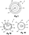
- the closure part 3 is formed circular or disc-shaped, in particular also the 10 and 11 is removable.
- a defined in particular by the recess 21 mounting portion 18 of the closure member 3 is further provided, in particular the peripheral of the recess 21 a bead of material 42 (see Fig. 10 ), in particular a bead-shaped material reinforcement, in order to ensure a secure hold of the closure part 3 on the attachment projection 20 of the cover part 2.
- the closure part 3 Starting from the circular peripheral lower end face 16 of the closure part 3 to the fastening region 18, the closure part 3 has a central part 14 with a lower rising surface 26 and an upper surface 27, the latter facing the inner sides 22 of the lid part 2.
- the lower rising surface 26 faces the housing interior and in particular the filter 8.
- the middle part 14 is formed rising from the lower end face 16 of the outer edge 15 to the mounting portion 18 toward, that is in particular formed at an angle to a central axis 30 of the speaking valve 1.
- a space 13 is formed between the closure part 3, in particular its lower rising surface 26 of the middle part 14 and an upper side of the filter 8, in which air which is inhaled through the inflow openings 6 can swirl, so that it then flows uniformly through the filter 8 Penetrates by inhalation, which also means a uniform moistening and warming experiences.
- the space is designed in such a way that air flowing in through the inflow openings 6 is inhaled without whistling noises.
- the inflow openings 6 are particularly preferably on a plane of the housing part 4 arranged circumferentially in the interior. They are of webs that connect the lower housing part with the upper edge 34 of the housing part 4, interrupted. As a result, a sufficient stability of the housing part 4 is given, which incidentally also the Fig. 5 to 7 is removable.
- the lower end face 16 of the outer edge 15 of the closure part 3 and the lip member 1 7 cooperates with the valve seat 5 in the transfer of the speaking valve 1 from the open position to a closed position.
- a force F in the direction of in Fig. 1 shown arrow on an upper surface 28 of the cover part 2 deforms the cover part formed of an elastic material 2 and thus allows a cooperation of the lower end face 16 of the closure part 3 and the lip member 17 with the valve seat surface of the valve seat 5.
- Due to the lip member 17 takes place while a largely airtight sealing of the valve in such a closed position, so that no air can be inhaled or exhaled through the inlet openings 6.
- the closure part 3 is made of a medical silicone and has a certain strength, but also a certain elasticity, so that due to this elasticity in particular of the lip or elements 17, the sealing effect on transfer of the speech valve 1 according to the invention from the open position to the closed position is supported.
- the housing part 4 is in contrast made of a hard, rigid plastic material, which has only a low elasticity, if any.
- Reference numeral 60 designates a region of the closure part 3 which lies above the upper surface 27 of the middle part 14 of the closure part 3. This is to clarify that this region 60 can also be formed filled, that is, up to this level, which is determined by the upper end face of the material bead 42 of the outer edge 15, the closure part 3 may be formed filled, that is, in this case represents a circular disc with a recess 21 in the middle, to which then a lower rising surface 26 of the central part 14 extends.
- the closure part 3 can be addressed as cone-like.
- the cover part 2 has a lower end face 29 in the region which projects vertically beyond an outer contour of the housing part 4. In addition, the cover part 2 projects beyond an outer contour of the housing part 4 in the horizontal direction, that is to say perpendicular to the central axis 30. In this way, air, as indicated by the arrow 12, can be inhaled through the inflow openings 6, whereby the inhaled air is preheated due to the proximity of the lower end surface 29 to a skin surface of the support of the speaking valve. 1 Fig. 1 In this case, it can also be provided that the lower end face 29 of the cover part 2 ends approximately at the level of the valve seat 5, which preferably corresponds to a lower edge of the inflow opening 6. This also achieves adequate preheating of the respiratory air.
- the speaking valve 1 can be made particularly small-sized, which represents a particular advantage.
- the inflow openings 6 can also be provided with a low height, preferably with a height that is equal to or slightly smaller than a height of the outer wall 19 of the outer edge 15 of the closure part 5.
- a height of the outer wall 19 of the outer edge 15 of the closure part 5 can also be provided with a low height, preferably with a height that is equal to or slightly smaller than a height of the outer wall 19 of the outer edge 15 of the closure part 5.
- Fig. 2 shows an alternative embodiment of a speaking valve 1 according to the invention in a sectional view.
- an upper side of the filter 8 does not abut with a valve seat surface of the valve seat 5, but projects beyond it distally.
- the closure part 3 at least partially cooperates with the lower end face 16 of the outer wall 15 with the valve seat 5, in particular in the region of the lip element 17, the filter 8 being slightly partially compressed.
- the filter 8 is, as usual, from an open-pored Foam material formed, which has a certain elasticity and thus a certain resilience, and therefore supports the cover part 2 in its resilience due to the use of an elastic material.
- the housing part 4 for this purpose four locking projections 32.1 to 32.4, which engage in the corresponding portions of the only partially annular circumferential annular groove 24.
- the fastening projection 20 is formed like a knob with a circumferential annular groove into which the fastening region 18 of the closure part 3 can be engaged. Due to the somewhat thickened design of the fastening projection 20, in conjunction with the elasticity of the material of the cover part 2, a secure arrangement of the closure part 3 on the inside 22 of the cover part 2 is thereby made possible.
- the lid part 24 is formed from an elastic material, whereas the closure part 3 is formed from a considerably more rigid, that is stronger material than the lid part 2. Nevertheless, the closure part 3 in particular a certain elasticity still on to a best possible sealing effect to achieve upon transfer of the speaking valve 1 in the closed position in cooperation with the valve seat surface of the valve seat 5.
- a tracheostoma patch 50 into which the housing part 4 of the speaking valve 1 can be received in a receptacle 52 with an outer wall 54.
- the receptacle has a bottom plate 51.
- the tracheostoma patch 50 has proximally a particular annularly formed adhesive tape 56, disposed on an underside of the bottom plate 51, by means of which this can be attached to the skin of a wearer.
- the speaking valve according to the Fig. 1 and 2 also be included in a tracheostomy tube, which includes the outer wall 25 of the housing part 4 with their recording.
- the 3 and 4 show perspective embodiments of the second embodiment according to Fig. 2 ,
- the design of the support cross 11 can be seen, which carries the filter 8.
- the filter 8 is held by the support cross 11 and prevented from slipping when breathing into the trachea.
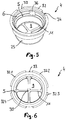
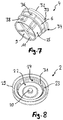
- the Fig. 5 and 7 show the housing part 4, as this example, in the second embodiment according to the Fig. 2 to 4 the speaking valve 1 according to the invention can be used.
- This has a total of 4 inflow 6, which are interrupted by a total of four webs 36 which connect a lower part of the housing part 4 with the upper edge 34 thereof.
- a total of four locking projections 32.1 to 32.4 are arranged, which can cooperate with the at least partially encircling annular groove 24 of a cover part 2, we already described above.
- the configuration of the support cross 11 with the total of four support arms and accordingly formed four outlet openings 9 is clearly visible.
- the valve seat 5 forms a valve seat surface due to a cross-sectional constriction of the housing part 4.
- Fig. 7 are still refer to locking aids 38, the recording of the speech valve according to the invention in a tracheostoma 50, as in the Fig. 2 to 4 or serve or facilitate a tracheal cannula. These are accommodated in the housing wall 25 of the housing part. 4
- the Fig. 8 and 9 show a cover part 2, as this in the speaking valve 1 according to the invention, in particular in that according to the second embodiment of the Fig. 2 to 4 , can be used.
- the cover part 2 shown there is designed so that it has an annular groove 24, which is only partially circumferentially annular, as this is of filling elements 31, and a total of four, is interrupted, so that the cover part 2 shown there fitting on a housing part 4 according to the Fig. 5 to 7 must be arranged.
- the filling elements 31 can also be omitted, so that such a precise arrangement is no longer necessary. Otherwise, the function and the design of the cover part according to the Fig. 8 and 9 already in connection with the first and second embodiments of the speaking valve 1 according to the invention Fig. 1 to 4 been described.
- the 10 and 11 Now show an inventive closure part 3, as this particular in a speaking valve 1 according to the Fig. 1 to 4 can be used.
- a fastening region 18 can clearly be seen with a recess 21 surrounded by a bead of material 42.
- the closure part 3 has an outer edge 15 with a lower end face 16 and an upper end face 40 and one from the lower end face 16 to the fastening region 18
- the middle part 14 forms an upper surface 27 and a lower surface 26, wherein above the upper surface 27 up to the upper end face 40 of the outer edge 15 and the bulge material 42 out of such dimensions defined area can also be formed filled as indicated by reference numeral 60 in FIG Fig. 1 explained in a principled way.
- the outer edge 15 has an outer wall 19, which in particular a secure guidance of the closure part within a speaking valve according to one of the embodiments 1 to 4 used for transfer from an open position to a closed position and from the closed position back to the open position.
- a restoring force is due to selection of the material, the shape and the cover part and can be adjusted. If the force is released onto the cover part or if the user leaves the cover part, this restoring force leads to reopening of the valve.
Landscapes
- Health & Medical Sciences (AREA)
- Pulmonology (AREA)
- General Health & Medical Sciences (AREA)
- Public Health (AREA)
- Veterinary Medicine (AREA)
- Biomedical Technology (AREA)
- Heart & Thoracic Surgery (AREA)
- Engineering & Computer Science (AREA)
- Life Sciences & Earth Sciences (AREA)
- Animal Behavior & Ethology (AREA)
- Hematology (AREA)
- Emergency Medicine (AREA)
- Anesthesiology (AREA)
- Otolaryngology (AREA)
- Cardiology (AREA)
- Oral & Maxillofacial Surgery (AREA)
- Transplantation (AREA)
- Vascular Medicine (AREA)
- Prostheses (AREA)
- Respiratory Apparatuses And Protective Means (AREA)
Claims (13)
- Valve de phonation (1) pour laryngectomisés ou trachéotomisés qui comporte une partie couvercle (2), une partie boitier (4) et un filtre (8) placé dans la partie boitier (4), ladite partie couvercle (2) étant disposée au moyen d'une liaison d'encliquetage au niveau de ladite partie boitier (4), ladite partie boitier (4) comportant distalement un siège de valve (5), ladite partie couvercle (2) comportant une partie verrouillage (3) orientée vers ledit filtre (8), disposée sur un côté interne (22) de celle-ci, ladite partie couvercle (2) étant constituée d'une matière élastique, ladite partie verrouillage (3) fermant ladite valve de phonation (1) à distance dudit filtre (8) par déformation d'au moins une zone de ladite partie couvercle (2), ladite partie verrouillage (3) comportant sur une face frontale (16) inférieure d'un bord externe (15) au moins un élément de lèvre (17), ledit élément de lèvre (17) interagissant avec ledit siège de valve (5) lors de l'actionnement de ladite valve de phonation (1), ladite partie verrouillage (3) étant circulaire, et comportant en partant de ladite face frontale (16) inférieure dudit bord externe (15), vers une zone de fixation (18) disposée au milieu, une surface (26) croissante d'une partie centrale (14), et ladite partie boitier (4) comprenant à distance dudit siège de valve (5) des ouvertures d'admission (6) qui, lors de l'actionnement de ladite valve de phonation (1), peuvent être fermées au moyen de ladite partie verrouillage (3) et au moins une zone élastique de ladite partie couvercle (2) fonctionnant en tant qu'élément de rappel.
- Valve de phonation selon la revendication 1, caractérisée en ce que ledit bord externe (15) comporte une paroi extérieure (19) qui est disposée essentiellement parallèlement à un contour intérieur de ladite partie boitier (4).
- Valve de phonation selon l'une ou plusieurs des précédentes revendications, caractérisée en ce que ladite zone de fixation (18) comporte un évidement (21), dans lequel une saillie de fixation (20) de ladite partie couvercle (2) peut être en prise.
- Valve de phonation selon l'une ou plusieurs des précédentes revendications, caractérisée en ce que ladite face frontale (16) inférieure de ladite partie verrouillage (3) interagit au moins en partie avec ledit siège de valve (5).
- Valve de phonation selon l'une ou plusieurs des précédentes revendications, caractérisée en ce qu'au moins une ouverture d'admission (6) comporte en direction d'un axe médian (30) de ladite valve (1) une hauteur qui est à peu près inférieure ou égale à une hauteur dudit bord externe (15) de ladite partie verrouillage (3).
- Valve de phonation selon l'une ou plusieurs des précédentes revendications, caractérisée en ce que ladite partie couvercle (2) est disposée, de manière amovible, sur ladite partie boitier (4).
- Valve de phonation selon l'une ou plusieurs des précédentes revendications, caractérisée en ce que ladite partie couvercle (2) comporte sur son coté interne (22) au moins un élément d'encliquetage (23), qui forme au moins une rainure (24) au moins en partie circulaire.
- Valve de phonation selon l'une ou plusieurs des précédentes revendications, caractérisée en ce que ladite partie verrouillage (3) est formée, en tant que ladite partie couvercle (2), en un matériau rigide.
- Valve de phonation selon l'une ou plusieurs des précédentes revendications, caractérisée en ce que ladite partie couvercle (2) dépasse ladite partie boitier (4) au moins en partie sur un côté extérieur.
- Valve de phonation selon l'une ou plusieurs des précédentes revendications, caractérisée en ce que ladite partie couvercle (2) dépasse ladite partie boitier (4) latéralement et verticalement.
- Valve de phonation selon l'une ou plusieurs des précédentes revendications, caractérisée en ce que ledit filtre (8) est disposé avec un ajustement de transition ou ajustement avec serrage dans ladite partie boitier (4).
- Valve de phonation selon l'une ou plusieurs des précédentes revendications, caractérisée en ce que ledit filtre (8) est comprimé en partie par l'actionnement de ladite valve de phonation (1).
- Partie verrouillage (3) pour une valve de phonation (1) pour laryngectomisés ou trachéotomisés, selon l'une des revendications 1 à 12, caractérisée en ce que ladite partie verrouillage (3) comporte sur une face frontale (16) inférieure d'un bord externe (15) au moins un élément de lèvre (17), ladite partie verrouillage (3) étant circulaire, et comportant en partant de la face frontale (16) inférieure dudit bord externe (15), vers une zone de fixation (18) disposée au milieu, une surface (26) croissante d'une partie centrale (14).
Applications Claiming Priority (2)
| Application Number | Priority Date | Filing Date | Title |
|---|---|---|---|
| DE102015105496.5A DE102015105496B4 (de) | 2015-04-10 | 2015-04-10 | Sprechventil mit Deckelteil, umfassend ein Verschlussteil mit einem ansteigenden Mittelteil |
| PCT/EP2016/057489 WO2016162365A1 (fr) | 2015-04-10 | 2016-04-06 | Valve de phonation comprenant une partie couvercle pourvue d'une partie clapet à partie médiane inclinée vers le haut |
Publications (2)
| Publication Number | Publication Date |
|---|---|
| EP3280356A1 EP3280356A1 (fr) | 2018-02-14 |
| EP3280356B1 true EP3280356B1 (fr) | 2018-11-28 |
Family
ID=55701944
Family Applications (1)
| Application Number | Title | Priority Date | Filing Date |
|---|---|---|---|
| EP16715497.0A Active EP3280356B1 (fr) | 2015-04-10 | 2016-04-06 | Valve de phonation comprenant une partie couvercle pourvue d'une partie clapet à partie médiane inclinée vers le haut |
Country Status (5)
| Country | Link |
|---|---|
| US (1) | US10478287B2 (fr) |
| EP (1) | EP3280356B1 (fr) |
| CN (1) | CN108124425B (fr) |
| DE (1) | DE102015105496B4 (fr) |
| WO (1) | WO2016162365A1 (fr) |
Families Citing this family (9)
| Publication number | Priority date | Publication date | Assignee | Title |
|---|---|---|---|---|
| JP5774825B2 (ja) * | 2010-08-19 | 2015-09-09 | ソニー株式会社 | 3次元造形装置及び造形物の製造方法 |
| WO2016162065A1 (fr) * | 2015-04-09 | 2016-10-13 | Andreas Fahl Medizintechnik-Vertrieb Gmbh | Couvercle pour un boîtier de nez artificiel |
| IT201700018291A1 (it) * | 2017-02-17 | 2018-08-17 | Biomed Device S R L | Dispositivo per il contenimento di liquidi biologici |
| DE102017130662B4 (de) * | 2017-12-20 | 2019-08-14 | Andreas Fahl Medizintechnik-Vertrieb Gmbh | Wärme- und Feuchtigkeitsaustauscher |
| US12377237B2 (en) * | 2019-02-15 | 2025-08-05 | Coloplast A/S | Breathing protector |
| CN119524282A (zh) | 2019-03-18 | 2025-02-28 | 瑞思迈私人有限公司 | 用于患者接口的充气室插入件 |
| DE102019131549A1 (de) * | 2019-11-21 | 2021-05-27 | Hamilton Medical Ag | Anschlussbauteil für eine Trachealkanüle, insbesondere zum Schutz vor unbeabsichtigtem Verschließen derselben |
| US11406492B1 (en) * | 2020-09-22 | 2022-08-09 | Robert T. Sataloff | Vocal fold prosthesis and method for removal of laryngeal web |
| DE102024001619A1 (de) * | 2024-05-17 | 2025-11-20 | Primed Halberstadt Medizintechnik Gmbh | Sprechventil und Verfahren zum Einsatz des Sprechventiles an einer tracheotomierten Person |
Family Cites Families (6)
| Publication number | Priority date | Publication date | Assignee | Title |
|---|---|---|---|---|
| US4582058A (en) | 1984-11-26 | 1986-04-15 | Bivona, Inc. | Tracheostoma valves |
| SE511530C2 (sv) * | 1993-12-23 | 1999-10-11 | Atos Medical Ab | Anordning vid ett i halsen upptaget stoma |
| SE512029C2 (sv) | 1998-05-14 | 2000-01-17 | Atos Medical Ab | Talventil med filter |
| ES2793245T3 (es) * | 2007-04-30 | 2020-11-13 | Atos Medical Ab | Protector respiratorio |
| ES2625327T3 (es) * | 2008-11-28 | 2017-07-19 | Atos Medical Ab | Dispositivo protector de respiración |
| DE102012109916A1 (de) * | 2012-10-17 | 2014-04-17 | Tracoe Medical Gmbh | Sprechventil |
-
2015
- 2015-04-10 DE DE102015105496.5A patent/DE102015105496B4/de active Active
-
2016
- 2016-04-06 WO PCT/EP2016/057489 patent/WO2016162365A1/fr not_active Ceased
- 2016-04-06 US US15/565,545 patent/US10478287B2/en active Active - Reinstated
- 2016-04-06 EP EP16715497.0A patent/EP3280356B1/fr active Active
- 2016-04-06 CN CN201680034634.6A patent/CN108124425B/zh active Active
Non-Patent Citations (1)
| Title |
|---|
| None * |
Also Published As
| Publication number | Publication date |
|---|---|
| CN108124425A (zh) | 2018-06-05 |
| DE102015105496A1 (de) | 2016-10-13 |
| US10478287B2 (en) | 2019-11-19 |
| EP3280356A1 (fr) | 2018-02-14 |
| DE102015105496B4 (de) | 2021-03-25 |
| CN108124425B (zh) | 2019-12-06 |
| US20180071083A1 (en) | 2018-03-15 |
| WO2016162365A1 (fr) | 2016-10-13 |
Similar Documents
| Publication | Publication Date | Title |
|---|---|---|
| EP3280356B1 (fr) | Valve de phonation comprenant une partie couvercle pourvue d'une partie clapet à partie médiane inclinée vers le haut | |
| DE69920440T2 (de) | Stimmventil mit filter | |
| DE102010048317B4 (de) | Künstliche Nase mit Sprechventil | |
| EP3107492B1 (fr) | Valve de phonation à partie couvercle comprenant un élément de fermeture sous forme de piston | |
| EP3107493B1 (fr) | Valve de phonation dotée d'une partie couvercle réalisée au moins en partie dans un matériau élastique | |
| EP3551267B1 (fr) | Échangeur de chaleur et d'humidité | |
| DE10126807A1 (de) | Inhalationstherapiegerät mit einem Ventil zur Begrenzung des Inspirationsflusses | |
| EP3233168B1 (fr) | Boîtier d'un échangeur de chaleur humide et procédé permettant le détachement d'un couvercle d'un boîtier | |
| EP3496670A1 (fr) | Manchon de prothèse | |
| WO2015062741A1 (fr) | Valve phonique pour des patients laryngectomisés ou trachéotomisés | |
| EP2953674B1 (fr) | Pansement pour trachéotomie | |
| AT507502B1 (de) | Selbstschliessendes medizinisches abschlussorgan | |
| EP3233167B1 (fr) | Protection trachéotomique | |
| EP2934384B1 (fr) | Valve de phonation | |
| EP2836266B1 (fr) | Support pour valves de phonation et/ou échangeurs de chaleur et d'humidité et échangeurs de chaleur et d'humidité adaptés à celui-ci | |
| EP1504731A1 (fr) | Prothèse vocale | |
| EP3727538B1 (fr) | Canule de trachéotomie comportant une ouverture de phonation | |
| DE19543169A1 (de) | Endotrachealkanüle | |
| EP1719535B1 (fr) | Dispositif d'acces pour tracheotomie | |
| WO2025237457A1 (fr) | Valve de phonation et procédé d'utilisation de la valve de phonation sur un patient ayant subi une trachéotomie | |
| DE202005020018U1 (de) | Tracheostomaplatzhalter | |
| EP3603567A1 (fr) | Prothèse ainsi qu'ensemble de mise à niveau pour une prothèse |
Legal Events
| Date | Code | Title | Description |
|---|---|---|---|
| STAA | Information on the status of an ep patent application or granted ep patent |
Free format text: STATUS: THE INTERNATIONAL PUBLICATION HAS BEEN MADE |
|
| PUAI | Public reference made under article 153(3) epc to a published international application that has entered the european phase |
Free format text: ORIGINAL CODE: 0009012 |
|
| STAA | Information on the status of an ep patent application or granted ep patent |
Free format text: STATUS: REQUEST FOR EXAMINATION WAS MADE |
|
| 17P | Request for examination filed |
Effective date: 20171107 |
|
| AK | Designated contracting states |
Kind code of ref document: A1 Designated state(s): AL AT BE BG CH CY CZ DE DK EE ES FI FR GB GR HR HU IE IS IT LI LT LU LV MC MK MT NL NO PL PT RO RS SE SI SK SM TR |
|
| AX | Request for extension of the european patent |
Extension state: BA ME |
|
| GRAP | Despatch of communication of intention to grant a patent |
Free format text: ORIGINAL CODE: EPIDOSNIGR1 |
|
| STAA | Information on the status of an ep patent application or granted ep patent |
Free format text: STATUS: GRANT OF PATENT IS INTENDED |
|
| DAX | Request for extension of the european patent (deleted) | ||
| INTG | Intention to grant announced |
Effective date: 20180612 |
|
| DAV | Request for validation of the european patent (deleted) | ||
| GRAS | Grant fee paid |
Free format text: ORIGINAL CODE: EPIDOSNIGR3 |
|
| GRAA | (expected) grant |
Free format text: ORIGINAL CODE: 0009210 |
|
| STAA | Information on the status of an ep patent application or granted ep patent |
Free format text: STATUS: THE PATENT HAS BEEN GRANTED |
|
| AK | Designated contracting states |
Kind code of ref document: B1 Designated state(s): AL AT BE BG CH CY CZ DE DK EE ES FI FR GB GR HR HU IE IS IT LI LT LU LV MC MK MT NL NO PL PT RO RS SE SI SK SM TR |
|
| REG | Reference to a national code |
Ref country code: CH Ref legal event code: EP |
|
| REG | Reference to a national code |
Ref country code: AT Ref legal event code: REF Ref document number: 1069348 Country of ref document: AT Kind code of ref document: T Effective date: 20181215 |
|
| REG | Reference to a national code |
Ref country code: DE Ref legal event code: R096 Ref document number: 502016002644 Country of ref document: DE |
|
| REG | Reference to a national code |
Ref country code: IE Ref legal event code: FG4D Free format text: LANGUAGE OF EP DOCUMENT: GERMAN |
|
| REG | Reference to a national code |
Ref country code: SE Ref legal event code: TRGR |
|
| REG | Reference to a national code |
Ref country code: NL Ref legal event code: FP |
|
| REG | Reference to a national code |
Ref country code: LT Ref legal event code: MG4D |
|
| PG25 | Lapsed in a contracting state [announced via postgrant information from national office to epo] |
Ref country code: FI Free format text: LAPSE BECAUSE OF FAILURE TO SUBMIT A TRANSLATION OF THE DESCRIPTION OR TO PAY THE FEE WITHIN THE PRESCRIBED TIME-LIMIT Effective date: 20181128 Ref country code: BG Free format text: LAPSE BECAUSE OF FAILURE TO SUBMIT A TRANSLATION OF THE DESCRIPTION OR TO PAY THE FEE WITHIN THE PRESCRIBED TIME-LIMIT Effective date: 20190228 Ref country code: HR Free format text: LAPSE BECAUSE OF FAILURE TO SUBMIT A TRANSLATION OF THE DESCRIPTION OR TO PAY THE FEE WITHIN THE PRESCRIBED TIME-LIMIT Effective date: 20181128 Ref country code: LV Free format text: LAPSE BECAUSE OF FAILURE TO SUBMIT A TRANSLATION OF THE DESCRIPTION OR TO PAY THE FEE WITHIN THE PRESCRIBED TIME-LIMIT Effective date: 20181128 Ref country code: ES Free format text: LAPSE BECAUSE OF FAILURE TO SUBMIT A TRANSLATION OF THE DESCRIPTION OR TO PAY THE FEE WITHIN THE PRESCRIBED TIME-LIMIT Effective date: 20181128 Ref country code: LT Free format text: LAPSE BECAUSE OF FAILURE TO SUBMIT A TRANSLATION OF THE DESCRIPTION OR TO PAY THE FEE WITHIN THE PRESCRIBED TIME-LIMIT Effective date: 20181128 Ref country code: IS Free format text: LAPSE BECAUSE OF FAILURE TO SUBMIT A TRANSLATION OF THE DESCRIPTION OR TO PAY THE FEE WITHIN THE PRESCRIBED TIME-LIMIT Effective date: 20190328 Ref country code: NO Free format text: LAPSE BECAUSE OF FAILURE TO SUBMIT A TRANSLATION OF THE DESCRIPTION OR TO PAY THE FEE WITHIN THE PRESCRIBED TIME-LIMIT Effective date: 20190228 |
|
| PG25 | Lapsed in a contracting state [announced via postgrant information from national office to epo] |
Ref country code: PT Free format text: LAPSE BECAUSE OF FAILURE TO SUBMIT A TRANSLATION OF THE DESCRIPTION OR TO PAY THE FEE WITHIN THE PRESCRIBED TIME-LIMIT Effective date: 20190328 Ref country code: AL Free format text: LAPSE BECAUSE OF FAILURE TO SUBMIT A TRANSLATION OF THE DESCRIPTION OR TO PAY THE FEE WITHIN THE PRESCRIBED TIME-LIMIT Effective date: 20181128 Ref country code: GR Free format text: LAPSE BECAUSE OF FAILURE TO SUBMIT A TRANSLATION OF THE DESCRIPTION OR TO PAY THE FEE WITHIN THE PRESCRIBED TIME-LIMIT Effective date: 20190301 Ref country code: RS Free format text: LAPSE BECAUSE OF FAILURE TO SUBMIT A TRANSLATION OF THE DESCRIPTION OR TO PAY THE FEE WITHIN THE PRESCRIBED TIME-LIMIT Effective date: 20181128 |
|
| PG25 | Lapsed in a contracting state [announced via postgrant information from national office to epo] |
Ref country code: IT Free format text: LAPSE BECAUSE OF FAILURE TO SUBMIT A TRANSLATION OF THE DESCRIPTION OR TO PAY THE FEE WITHIN THE PRESCRIBED TIME-LIMIT Effective date: 20181128 Ref country code: CZ Free format text: LAPSE BECAUSE OF FAILURE TO SUBMIT A TRANSLATION OF THE DESCRIPTION OR TO PAY THE FEE WITHIN THE PRESCRIBED TIME-LIMIT Effective date: 20181128 Ref country code: PL Free format text: LAPSE BECAUSE OF FAILURE TO SUBMIT A TRANSLATION OF THE DESCRIPTION OR TO PAY THE FEE WITHIN THE PRESCRIBED TIME-LIMIT Effective date: 20181128 Ref country code: DK Free format text: LAPSE BECAUSE OF FAILURE TO SUBMIT A TRANSLATION OF THE DESCRIPTION OR TO PAY THE FEE WITHIN THE PRESCRIBED TIME-LIMIT Effective date: 20181128 |
|
| REG | Reference to a national code |
Ref country code: DE Ref legal event code: R097 Ref document number: 502016002644 Country of ref document: DE |
|
| PG25 | Lapsed in a contracting state [announced via postgrant information from national office to epo] |
Ref country code: EE Free format text: LAPSE BECAUSE OF FAILURE TO SUBMIT A TRANSLATION OF THE DESCRIPTION OR TO PAY THE FEE WITHIN THE PRESCRIBED TIME-LIMIT Effective date: 20181128 Ref country code: SM Free format text: LAPSE BECAUSE OF FAILURE TO SUBMIT A TRANSLATION OF THE DESCRIPTION OR TO PAY THE FEE WITHIN THE PRESCRIBED TIME-LIMIT Effective date: 20181128 Ref country code: SK Free format text: LAPSE BECAUSE OF FAILURE TO SUBMIT A TRANSLATION OF THE DESCRIPTION OR TO PAY THE FEE WITHIN THE PRESCRIBED TIME-LIMIT Effective date: 20181128 Ref country code: RO Free format text: LAPSE BECAUSE OF FAILURE TO SUBMIT A TRANSLATION OF THE DESCRIPTION OR TO PAY THE FEE WITHIN THE PRESCRIBED TIME-LIMIT Effective date: 20181128 |
|
| PLBE | No opposition filed within time limit |
Free format text: ORIGINAL CODE: 0009261 |
|
| STAA | Information on the status of an ep patent application or granted ep patent |
Free format text: STATUS: NO OPPOSITION FILED WITHIN TIME LIMIT |
|
| 26N | No opposition filed |
Effective date: 20190829 |
|
| REG | Reference to a national code |
Ref country code: CH Ref legal event code: PL |
|
| REG | Reference to a national code |
Ref country code: BE Ref legal event code: MM Effective date: 20190430 |
|
| PG25 | Lapsed in a contracting state [announced via postgrant information from national office to epo] |
Ref country code: LU Free format text: LAPSE BECAUSE OF NON-PAYMENT OF DUE FEES Effective date: 20190406 Ref country code: MC Free format text: LAPSE BECAUSE OF FAILURE TO SUBMIT A TRANSLATION OF THE DESCRIPTION OR TO PAY THE FEE WITHIN THE PRESCRIBED TIME-LIMIT Effective date: 20181128 |
|
| PG25 | Lapsed in a contracting state [announced via postgrant information from national office to epo] |
Ref country code: CH Free format text: LAPSE BECAUSE OF NON-PAYMENT OF DUE FEES Effective date: 20190430 Ref country code: LI Free format text: LAPSE BECAUSE OF NON-PAYMENT OF DUE FEES Effective date: 20190430 |
|
| PG25 | Lapsed in a contracting state [announced via postgrant information from national office to epo] |
Ref country code: BE Free format text: LAPSE BECAUSE OF NON-PAYMENT OF DUE FEES Effective date: 20190430 |
|
| PG25 | Lapsed in a contracting state [announced via postgrant information from national office to epo] |
Ref country code: TR Free format text: LAPSE BECAUSE OF FAILURE TO SUBMIT A TRANSLATION OF THE DESCRIPTION OR TO PAY THE FEE WITHIN THE PRESCRIBED TIME-LIMIT Effective date: 20181128 |
|
| PG25 | Lapsed in a contracting state [announced via postgrant information from national office to epo] |
Ref country code: IE Free format text: LAPSE BECAUSE OF NON-PAYMENT OF DUE FEES Effective date: 20190406 |
|
| PG25 | Lapsed in a contracting state [announced via postgrant information from national office to epo] |
Ref country code: CY Free format text: LAPSE BECAUSE OF FAILURE TO SUBMIT A TRANSLATION OF THE DESCRIPTION OR TO PAY THE FEE WITHIN THE PRESCRIBED TIME-LIMIT Effective date: 20181128 |
|
| PG25 | Lapsed in a contracting state [announced via postgrant information from national office to epo] |
Ref country code: MT Free format text: LAPSE BECAUSE OF FAILURE TO SUBMIT A TRANSLATION OF THE DESCRIPTION OR TO PAY THE FEE WITHIN THE PRESCRIBED TIME-LIMIT Effective date: 20181128 Ref country code: HU Free format text: LAPSE BECAUSE OF FAILURE TO SUBMIT A TRANSLATION OF THE DESCRIPTION OR TO PAY THE FEE WITHIN THE PRESCRIBED TIME-LIMIT; INVALID AB INITIO Effective date: 20160406 |
|
| PG25 | Lapsed in a contracting state [announced via postgrant information from national office to epo] |
Ref country code: SI Free format text: LAPSE BECAUSE OF FAILURE TO SUBMIT A TRANSLATION OF THE DESCRIPTION OR TO PAY THE FEE WITHIN THE PRESCRIBED TIME-LIMIT Effective date: 20181128 |
|
| PG25 | Lapsed in a contracting state [announced via postgrant information from national office to epo] |
Ref country code: MK Free format text: LAPSE BECAUSE OF FAILURE TO SUBMIT A TRANSLATION OF THE DESCRIPTION OR TO PAY THE FEE WITHIN THE PRESCRIBED TIME-LIMIT Effective date: 20181128 |
|
| P01 | Opt-out of the competence of the unified patent court (upc) registered |
Effective date: 20230528 |
|
| PGFP | Annual fee paid to national office [announced via postgrant information from national office to epo] |
Ref country code: NL Payment date: 20250422 Year of fee payment: 10 |
|
| PGFP | Annual fee paid to national office [announced via postgrant information from national office to epo] |
Ref country code: DE Payment date: 20250428 Year of fee payment: 10 |
|
| PGFP | Annual fee paid to national office [announced via postgrant information from national office to epo] |
Ref country code: FR Payment date: 20250422 Year of fee payment: 10 |
|
| PGFP | Annual fee paid to national office [announced via postgrant information from national office to epo] |
Ref country code: AT Payment date: 20250416 Year of fee payment: 10 |
|
| PGFP | Annual fee paid to national office [announced via postgrant information from national office to epo] |
Ref country code: SE Payment date: 20250423 Year of fee payment: 10 |
|
| PGFP | Annual fee paid to national office [announced via postgrant information from national office to epo] |
Ref country code: GB Payment date: 20260327 Year of fee payment: 11 |