EP3280529B1 - Katalysatorzusammensetzung, deren verwendung, und katalytische verfahren zur herstellung von flüssigen kohlenwasserstoffen - Google Patents
Katalysatorzusammensetzung, deren verwendung, und katalytische verfahren zur herstellung von flüssigen kohlenwasserstoffen Download PDFInfo
- Publication number
- EP3280529B1 EP3280529B1 EP16776222.8A EP16776222A EP3280529B1 EP 3280529 B1 EP3280529 B1 EP 3280529B1 EP 16776222 A EP16776222 A EP 16776222A EP 3280529 B1 EP3280529 B1 EP 3280529B1
- Authority
- EP
- European Patent Office
- Prior art keywords
- extrudates
- silica
- potassium
- pellets
- hydrocarbons
- Prior art date
- Legal status (The legal status is an assumption and is not a legal conclusion. Google has not performed a legal analysis and makes no representation as to the accuracy of the status listed.)
- Active
Links
Images


Classifications
-
- B—PERFORMING OPERATIONS; TRANSPORTING
- B01—PHYSICAL OR CHEMICAL PROCESSES OR APPARATUS IN GENERAL
- B01J—CHEMICAL OR PHYSICAL PROCESSES, e.g. CATALYSIS OR COLLOID CHEMISTRY; THEIR RELEVANT APPARATUS
- B01J23/00—Catalysts comprising metals or metal oxides or hydroxides, not provided for in group B01J21/00
- B01J23/70—Catalysts comprising metals or metal oxides or hydroxides, not provided for in group B01J21/00 of the iron group metals or copper
- B01J23/74—Iron group metals
- B01J23/745—Iron
-
- B—PERFORMING OPERATIONS; TRANSPORTING
- B01—PHYSICAL OR CHEMICAL PROCESSES OR APPARATUS IN GENERAL
- B01J—CHEMICAL OR PHYSICAL PROCESSES, e.g. CATALYSIS OR COLLOID CHEMISTRY; THEIR RELEVANT APPARATUS
- B01J23/00—Catalysts comprising metals or metal oxides or hydroxides, not provided for in group B01J21/00
- B01J23/005—Spinels
-
- B—PERFORMING OPERATIONS; TRANSPORTING
- B01—PHYSICAL OR CHEMICAL PROCESSES OR APPARATUS IN GENERAL
- B01J—CHEMICAL OR PHYSICAL PROCESSES, e.g. CATALYSIS OR COLLOID CHEMISTRY; THEIR RELEVANT APPARATUS
- B01J23/00—Catalysts comprising metals or metal oxides or hydroxides, not provided for in group B01J21/00
- B01J23/02—Catalysts comprising metals or metal oxides or hydroxides, not provided for in group B01J21/00 of the alkali- or alkaline earth metals or beryllium
-
- B—PERFORMING OPERATIONS; TRANSPORTING
- B01—PHYSICAL OR CHEMICAL PROCESSES OR APPARATUS IN GENERAL
- B01J—CHEMICAL OR PHYSICAL PROCESSES, e.g. CATALYSIS OR COLLOID CHEMISTRY; THEIR RELEVANT APPARATUS
- B01J23/00—Catalysts comprising metals or metal oxides or hydroxides, not provided for in group B01J21/00
- B01J23/70—Catalysts comprising metals or metal oxides or hydroxides, not provided for in group B01J21/00 of the iron group metals or copper
- B01J23/76—Catalysts comprising metals or metal oxides or hydroxides, not provided for in group B01J21/00 of the iron group metals or copper combined with metals, oxides or hydroxides provided for in groups B01J23/02 - B01J23/36
- B01J23/78—Catalysts comprising metals or metal oxides or hydroxides, not provided for in group B01J21/00 of the iron group metals or copper combined with metals, oxides or hydroxides provided for in groups B01J23/02 - B01J23/36 with alkali- or alkaline earth metals
-
- B—PERFORMING OPERATIONS; TRANSPORTING
- B01—PHYSICAL OR CHEMICAL PROCESSES OR APPARATUS IN GENERAL
- B01J—CHEMICAL OR PHYSICAL PROCESSES, e.g. CATALYSIS OR COLLOID CHEMISTRY; THEIR RELEVANT APPARATUS
- B01J35/00—Catalysts, in general, characterised by their form or physical properties
- B01J35/40—Catalysts, in general, characterised by their form or physical properties characterised by dimensions, e.g. grain size
-
- B—PERFORMING OPERATIONS; TRANSPORTING
- B01—PHYSICAL OR CHEMICAL PROCESSES OR APPARATUS IN GENERAL
- B01J—CHEMICAL OR PHYSICAL PROCESSES, e.g. CATALYSIS OR COLLOID CHEMISTRY; THEIR RELEVANT APPARATUS
- B01J35/00—Catalysts, in general, characterised by their form or physical properties
- B01J35/60—Catalysts, in general, characterised by their form or physical properties characterised by their surface properties or porosity
- B01J35/61—Surface area
- B01J35/615—100-500 m2/g
-
- B—PERFORMING OPERATIONS; TRANSPORTING
- B01—PHYSICAL OR CHEMICAL PROCESSES OR APPARATUS IN GENERAL
- B01J—CHEMICAL OR PHYSICAL PROCESSES, e.g. CATALYSIS OR COLLOID CHEMISTRY; THEIR RELEVANT APPARATUS
- B01J35/00—Catalysts, in general, characterised by their form or physical properties
- B01J35/60—Catalysts, in general, characterised by their form or physical properties characterised by their surface properties or porosity
- B01J35/63—Pore volume
- B01J35/633—Pore volume less than 0.5 ml/g
-
- B—PERFORMING OPERATIONS; TRANSPORTING
- B01—PHYSICAL OR CHEMICAL PROCESSES OR APPARATUS IN GENERAL
- B01J—CHEMICAL OR PHYSICAL PROCESSES, e.g. CATALYSIS OR COLLOID CHEMISTRY; THEIR RELEVANT APPARATUS
- B01J35/00—Catalysts, in general, characterised by their form or physical properties
- B01J35/60—Catalysts, in general, characterised by their form or physical properties characterised by their surface properties or porosity
- B01J35/64—Pore diameter
- B01J35/647—2-50 nm
-
- B—PERFORMING OPERATIONS; TRANSPORTING
- B01—PHYSICAL OR CHEMICAL PROCESSES OR APPARATUS IN GENERAL
- B01J—CHEMICAL OR PHYSICAL PROCESSES, e.g. CATALYSIS OR COLLOID CHEMISTRY; THEIR RELEVANT APPARATUS
- B01J37/00—Processes, in general, for preparing catalysts; Processes, in general, for activation of catalysts
- B01J37/0009—Use of binding agents; Moulding; Pressing; Powdering; Granulating; Addition of materials ameliorating the mechanical properties of the product catalyst
-
- B—PERFORMING OPERATIONS; TRANSPORTING
- B01—PHYSICAL OR CHEMICAL PROCESSES OR APPARATUS IN GENERAL
- B01J—CHEMICAL OR PHYSICAL PROCESSES, e.g. CATALYSIS OR COLLOID CHEMISTRY; THEIR RELEVANT APPARATUS
- B01J37/00—Processes, in general, for preparing catalysts; Processes, in general, for activation of catalysts
- B01J37/02—Impregnation, coating or precipitation
- B01J37/03—Precipitation; Co-precipitation
- B01J37/031—Precipitation
-
- B—PERFORMING OPERATIONS; TRANSPORTING
- B01—PHYSICAL OR CHEMICAL PROCESSES OR APPARATUS IN GENERAL
- B01J—CHEMICAL OR PHYSICAL PROCESSES, e.g. CATALYSIS OR COLLOID CHEMISTRY; THEIR RELEVANT APPARATUS
- B01J37/00—Processes, in general, for preparing catalysts; Processes, in general, for activation of catalysts
- B01J37/08—Heat treatment
-
- B—PERFORMING OPERATIONS; TRANSPORTING
- B01—PHYSICAL OR CHEMICAL PROCESSES OR APPARATUS IN GENERAL
- B01J—CHEMICAL OR PHYSICAL PROCESSES, e.g. CATALYSIS OR COLLOID CHEMISTRY; THEIR RELEVANT APPARATUS
- B01J37/00—Processes, in general, for preparing catalysts; Processes, in general, for activation of catalysts
- B01J37/16—Reducing
- B01J37/18—Reducing with gases containing free hydrogen
-
- C—CHEMISTRY; METALLURGY
- C10—PETROLEUM, GAS OR COKE INDUSTRIES; TECHNICAL GASES CONTAINING CARBON MONOXIDE; FUELS; LUBRICANTS; PEAT
- C10G—CRACKING HYDROCARBON OILS; PRODUCTION OF LIQUID HYDROCARBON MIXTURES, e.g. BY DESTRUCTIVE HYDROGENATION, OLIGOMERISATION, POLYMERISATION; RECOVERY OF HYDROCARBON OILS FROM OIL-SHALE, OIL-SAND, OR GASES; REFINING MIXTURES MAINLY CONSISTING OF HYDROCARBONS; REFORMING OF NAPHTHA; MINERAL WAXES
- C10G2/00—Production of liquid hydrocarbon mixtures of undefined composition from oxides of carbon
- C10G2/30—Production of liquid hydrocarbon mixtures of undefined composition from oxides of carbon from carbon monoxide with hydrogen
- C10G2/32—Production of liquid hydrocarbon mixtures of undefined composition from oxides of carbon from carbon monoxide with hydrogen with the use of catalysts
- C10G2/33—Production of liquid hydrocarbon mixtures of undefined composition from oxides of carbon from carbon monoxide with hydrogen with the use of catalysts characterised by the catalyst used
- C10G2/331—Production of liquid hydrocarbon mixtures of undefined composition from oxides of carbon from carbon monoxide with hydrogen with the use of catalysts characterised by the catalyst used containing group VIII-metals
-
- C—CHEMISTRY; METALLURGY
- C10—PETROLEUM, GAS OR COKE INDUSTRIES; TECHNICAL GASES CONTAINING CARBON MONOXIDE; FUELS; LUBRICANTS; PEAT
- C10G—CRACKING HYDROCARBON OILS; PRODUCTION OF LIQUID HYDROCARBON MIXTURES, e.g. BY DESTRUCTIVE HYDROGENATION, OLIGOMERISATION, POLYMERISATION; RECOVERY OF HYDROCARBON OILS FROM OIL-SHALE, OIL-SAND, OR GASES; REFINING MIXTURES MAINLY CONSISTING OF HYDROCARBONS; REFORMING OF NAPHTHA; MINERAL WAXES
- C10G2/00—Production of liquid hydrocarbon mixtures of undefined composition from oxides of carbon
- C10G2/30—Production of liquid hydrocarbon mixtures of undefined composition from oxides of carbon from carbon monoxide with hydrogen
- C10G2/32—Production of liquid hydrocarbon mixtures of undefined composition from oxides of carbon from carbon monoxide with hydrogen with the use of catalysts
- C10G2/33—Production of liquid hydrocarbon mixtures of undefined composition from oxides of carbon from carbon monoxide with hydrogen with the use of catalysts characterised by the catalyst used
- C10G2/331—Production of liquid hydrocarbon mixtures of undefined composition from oxides of carbon from carbon monoxide with hydrogen with the use of catalysts characterised by the catalyst used containing group VIII-metals
- C10G2/332—Production of liquid hydrocarbon mixtures of undefined composition from oxides of carbon from carbon monoxide with hydrogen with the use of catalysts characterised by the catalyst used containing group VIII-metals of the iron-group
-
- B—PERFORMING OPERATIONS; TRANSPORTING
- B01—PHYSICAL OR CHEMICAL PROCESSES OR APPARATUS IN GENERAL
- B01J—CHEMICAL OR PHYSICAL PROCESSES, e.g. CATALYSIS OR COLLOID CHEMISTRY; THEIR RELEVANT APPARATUS
- B01J2523/00—Constitutive chemical elements of heterogeneous catalysts
Definitions
- pellets are rarely used as powders; they are usually employed as entities of larger size and/or better defined shapes, e.g., in the form of pellets, to prevent an unacceptably high pressure drop in gas-phase reactions in packed beds.
- pellet is used herein to indicate any discrete solid form created from powdered material by means of forming operations, typically through the application of pressure or compaction, for example, using an extruder to form extrudates, or a press to produce tablets or by granulation methods.
- the alumina-containing pellets are mechanically stronger, but in their presence, the selectivity of the reaction to the valuable C 5+ hydrocarbons, and especially to C 7+ hydrocarbons is unfortunately lower than the activity measured for a parallel reaction using the binder-free pellets.
- silica-containing pellets in particular extrudates, which are not only mechanically strong, but also display high catalytic activity, surpassing that of the binder-free pellets.
- an extrudable mass was achieved on combining the catalyst Fe 2+ (Fe 3+ y Al 3+ 1-y ) 2 O 4 with colloidal silica as the sole silica source, in a specific pH environment, more precisely, around neutral pH values.
- Extrusion of silica-rich solids, consisting of silica, zeolite or a mixture thereof to form extrudates with an acceptable physical strength is described in US 4,582,815 and US 5,053,374 .
- the preparation method according to the invention involves the gelation of a colloidal silica in the presence of Fe 2+ (Fe 3+ y Al 3+ 1-y ) 2 O 4 particles at a suitable pH, preferably in the range from 6.5 to 7.5, more preferably from 6.8 to 7.2.
- the so-formed gelled material is optionally dried, to give an extrudable mass with an acceptable moisture content, preferably from 40 to 45% (by weight), which is then formed into pellets (extrudates).
- the resultant extrudates after aging and drying, undergo a first calcination, followed by impregnation with potassium solution, and are then dried and calcined again, to give potassium-promoted Fe 2+ (Fe 3+ y Al 3+ 1-y ) 2 O 4 silica-containing extrudates with high mechanical strength and greatly improved catalytic activity which can find utility in a variety of processes of hydrocarbons production from carbon dioxide, that is, the reaction of carbon dioxide with hydrogen (produced by water splitting or by steam reforming of natural gas or other sources) to produce hydrocarbons, the reaction of carbon monoxide (produced by carbon dioxide splitting or other sources) with steam to produce hydrocarbons and conversion of H 2 -lean syngas (obtainable by dry reforming of natural gas or other sources) to hydrocarbons.
- the features of these processes are set out in detail below.
- a first aspect of the invention is a process for preparing potassium-promoted Fe 2+ (Fe 3+ y Al 3+ 1-y ) 2 O 4 , silica-containing pellets [0.3 ⁇ y ⁇ 0.7, preferably 0.4 ⁇ y ⁇ 0.6], comprising subjecting colloidal silica to gelation in the presence of Fe 2+ (Fe 3+ y Al 3+ 1-y ) 2 O 4 spinel particles, converting the gelled material into pellets and adding potassium to said pellets.
- the weight ratio Fe:Al:K in the catalyst preferably varies from 100:20:3 to 100:30:20.
- the active catalytic material Fe 2+ (Fe 3+ y Al 3+ 1-y ) 2 O 4 is prepared by a co-precipitation technique described in detail in WO 2014/111919 .
- the co-precipitation of the metals takes place to give the corresponding mixed hydroxides which on drying undergo dehydration whereby a spinel compound is formed, which is preferably free of a hematite or magnetite phases after calcination.
- Suitable starting materials for use in the preparation of the Fe 2+ (Fe 3+ y Al 3+ 1-y ) 2 O 4 catalyst are water-soluble ferric and aluminum salts, such as the nitrate salts.
- the two metal nitrates exist in hydrated forms: Fe(NO 3 ) 3 ⁇ 9H 2 O and Al(NO 3 ) 3 ⁇ 9H 2 O.
- the preferred concentrations of the ferric and aluminum salts in the aqueous solution are from 400 to 1200 g/liter and 200-600 g/liter and, respectively, with the relative amounts of the salts being adjusted to form the desired composition of the catalyst.
- the water-soluble metal salts e.g., the nitrates
- the weight ratio Al:Fe in the solution is not less than 20:100, e.g., from 20:100 to 30:100.
- the adjustment of the pH of the aqueous solution to the range from 6.0 to 8.5, especially between 7.5 and 8.5, e.g., around 8.0, in order to induce the co-precipitation of the metal hydroxides, is preferably accomplished by the gradual addition of an aqueous base solution, such as ammonium hydroxide solution, which solution is preferably applied in a dilute form, with concentration of not more than 5% by weight.
- an aqueous base solution such as ammonium hydroxide solution
- the precipitate formed is separated from the mother liquor, e.g., by filtration or any other solid/liquid separation technique, optionally washed with water and then dried at temperature in the range of 100-140°C for period of at least 3 hours, e.g., at least 6 hours.
- the spinel compound is combined with a suitable silica precursor.
- a reduced-particle size form of the spinel material is preferably employed. Particle size reduction could be achieved using conventional methods, e.g., with the aid of a milling device such as a ball mill.
- the Fe 2+ (Fe 3+ y Al 3+ 1-y ) 2 O 4 compound is milled to produce a population of particles (nanocrystalline aggregates) with particle size of less than 250 ⁇ m, preferably from 20 to 200 ⁇ m, as determined, for example, by laser light scattering (laser diffraction) method.
- a silica precursor useful as a starting material in the preparation of the pellets is an aqueous alkali-stabilized colloidal silica with amorphous silica particle size of up to 100nm, preferably up to 50 nm, e.g., from about 10 to 20 nm (nominal size), with the content of the silica in the dispersion varying from 20 to 40% by weight.
- Suitable colloidal silica are commercially available (for example, Ludox® HS originally from E I Du Pont de Nemours & Co and now from Grace & Co; two preferred grades are Ludox® HS-30 and Ludox® HS-40 which contain 30% and 40% silica, respectively).
- the amount of colloidal silica is from 90 to 100% weight percent of the total amount of silica used in the process; preferably, only colloidal silica is used as a silica source in forming the extrudates of this invention.
- the pH of the colloidal silica is reduced by the addition of a mineral acid, such as concentrated nitric acid, although other acids may also be used.
- a mineral acid such as concentrated nitric acid
- the pH of the system is reduced to within the range of below the alkaline pH threshold necessary to stabilize the colloidal silica starting material.
- setting the pH of the colloidal silica too low within the acidic regime can damage the structure of the spinel powder (the spinel is incompatible with either highly basic or acidic environment).
- a suitable pH window exists around neutral pH, e.g., from about 6.5 to 7.5, preferably from 6.8 to 7.2.
- the Fe 2+ (Fe 3+ y Al 3+ 1-y ) 2 O 4 powder is combined with the silica dispersion.
- the weight ratio Fe 2+ (Fe 3+ y Al 3+ 1-y ) 2 O 4 /SiO 2 in the mixture is preferably from 50:50 to 80:20, e.g., 55:45 to 75:25, more preferably from 65:35 to 75:25.
- a gel is formed.
- the Fe 2+ (Fe 3+ y Al 3+ 1-y ) 2 O 4 /SiO 2 -containing gel is optionally dried under kneading to adjust the consistency of the mass(e.g., to achieve water content of about 40-45 wt%), taken out from the vessel (kneader) and formed into pellets using conventional methods, including extrusion to produce extrudates or inserting in a perforated plate.
- the extrudates may be produced in different shapes and sizes; for example, cylindrical extrudates with diameter of 1.5-2.5 mm and length in the range from 3 to 15 mm.
- the invention provides extrudates, using an apparatus customary for this purpose, that is, extruders including single-screw or twin-screw extruders which can be co-rotating or counter-rotating.
- extruders including single-screw or twin-screw extruders which can be co-rotating or counter-rotating.
- the mass is fed through the feed inlet of an extruder and extruded through a die plate containing 2-4 mm diameter holes.
- the pellets are aged in air at room temperature for period of not less than 5 h, e.g., not less than 15 h, dried, e.g., in air at a temperature of not less than 100°C for a period of time of not less than 3 hours, e.g., not less than 6 hours, and then calcined in air at a temperature in the range from 300 to 400°C for not less than 3 hours.
- the catalytically active material Fe 2+ (Fe 3+ y Al 3+ 1-y ) 2 O 4 distributed within the pellet is essentially free of hematite or magnetite phases.
- potassium is loaded onto the pellets (e.g., extrudates).
- the potassium promoter may also be added to the catalyst at one of the early stages of the process, e.g., a portion of the desired amount of the promoter may be added to the Fe 2+ (Fe 3+ y Al 3+ 1-y ) 2 O 4 powder or to the Fe 2+ (Fe 3+ y Al 3+ 1-y ) 2 O 4 /SiO 2 -containing gel.
- the impregnation-drying cycle may be repeated several times.
- the weight ratio Fe:K is in the range from 100:3 to 100:20, for example, more than 100:10 and up to 100:18.
- the potassium-containing pellets are subjected to drying in air at a temperature in the range of 100-140°C for period of at least 3 hours, e.g., at least 6 hours followed by calcination in air at a temperature in the range from 400 to 500°C for period of at least 3 hours, e.g., at least 6 hours.
- the invention specifically relates to a process for preparing potassium-promoted Fe 2+ (Fe 3+ y Al 3+ 1-y ) 2 O 4 , silica-containing extrudates, comprising the following steps:
- the resultant potassium-promoted Fe 2+ (Fe 3+ y Al 3+ 1-y ) 2 O 4 , silica-containing pellets (e.g., extrudates) form another aspect of the invention.
- the pellets e.g., extrudates
- the extrudates comprise 45 to 85% by weight Fe 2+ (Fe 3+ y Al 3+ 1-y ) 2 O 4 , 10-50% by weight SiO 2 and 3 to 10% by weight potassium.
- the extrudates comprise 60 to 80% by weight Fe 2+ (Fe 3+ y Al 3+ 1-y ) 2 O 4 , 15-40% by weight SiO 2 and 4 to 8% by weight potassium.
- the extrudates of the invention exhibit surface area of not less than 130 m 2 /gram, e.g., between 150 and 220 m 2 /gram; pore volume of not less than 0.23 cm 3 /gram, e.g. between 0.25 and 0.40 cm 3 /gram, and average pore diameter between 6.0 and 8.0 nm. Elemental analysis by means of energy dispersive X-ray spectroscopy of the catalyst indicates that the weight ratio Fe:Al is in the range from 100:20 to 100:30. Analytical techniques and instruments used for the measurements reported herein are as described in WO 2014/111919 .
- Extrudates of 1.6 mm diameter prepared according to the invention display good mechanical properties, that is, a crush strength measured by Quantachrome Crush Strength Analyzer CSA-2 ranged from 11 to 26 N/mm, e.g., from 15 to 22 N/mm, and crushing force/circumference from 5 to 8 N/mm.
- the pellets e.g., extrudates
- a suitable reactor e.g., a continuous fixed bed reactor.
- the thickness of the catalyst layer packed in the reactor may vary within the range of 7 cm to 12 m, typically from 1 m to 12 m, provided the size of the pellets is chosen so as to avoid a significant pressure drop.
- the extrudates of the invention finds utility in a wide range of processes for preparing hydrocarbons from different feedstock materials, and in particular, the extrudates can effectively advance the conversion of carbon dioxide by hydrogenation to hydrocarbons, the conversion of carbon monoxide by reaction with steam to hydrocarbons and the conversion of H 2 -lean syngas (the product of dry reforming of natural gas) into hydrocarbons.
- the extrudates need first to undergo activation.
- the activation of the extrudates is carried out in-situ, by either reduction (hydrogenation) or carburization.
- Reduction involves the flow of hydrogen stream through the reactor in which the extrudates are placed at a temperature of not less than 400°C.
- the flow rate of the hydrogen stream is not less than 20cm 3 /min per gram of extrudates.
- the reduction is continued at atmospheric pressure for not less than 3 hours.
- Carburization involves the exposure of extrudates to a carbon-containing atmosphere. To this end, streams of carbon monoxide, hydrogen and an inert gas carrier are caused to flow through the reactor in which extrudates are placed at a temperature of not less than 300°C.
- the flow rates of the three gaseous components (CO, H 2 and inert gas (N 2 , He, Ar)) are at least 30:30:150 cm 3 /min per one gram of the extrudates, respectively.
- the carburization is continued at atmospheric pressure for not less than 3 hours.
- the carbon dioxide hydrogenation reaction is allowed to start.
- carbon dioxide-containing gaseous stream and hydrogen stream are continuously fed to the reactor at H 2 /CO 2 of not less than 1, e.g., not less than 2, and weight hourly space velocity (WHSV) not less than 0.1 h -1 , preferably not less than 0.5 h -1 and more preferably not less than 1 h -1 .
- the reaction is carried out at a temperature in the range from 250 to 360°C at pressure of not less than 5, e.g., not less 10 atmospheres, e.g., from 20 to 40.
- Another aspect of the invention is therefore a process for producing hydrocarbons comprising hydrogenation of carbon dioxide-containing gas stream in the presence of the potassium-promoted Fe 2+ (Fe 3+ y Al 3+ 1-y ) 2 O 4 , silica-containing pellets (e.g., extrudates) that were described above.
- carbon dioxide-containing gas stream used in the present invention may be neat carbon dioxide and also any gas mixture which contains carbon dioxide, for example, a mixture of carbon dioxide and carbon monoxide, with the molar fraction of carbon dioxide being not less than 0.25.
- the hydrogenation of carbon dioxide-containing gas stream may be carried out in the apparatus illustrated in Figure 4 of WO 2014/111919 , where the reactor configuration is based on a plurality of fixed bed reactors arranged in series. This figure is reproduced below as Figure 1 .
- the serially-positioned reactors are designated by numerals (1), (2) and (3).
- Each reactor is provided with a suitable amount of pellets (extrudates) loaded therein. The amount of pellets in each reactor is adjusted to improve conversion and productivity. Alternatively, the total amount of the pellets used in the process may be equally divided between the set of reactors.
- Each reactor is provided with a discharge line (4), with a cooler (5), a gas-liquid separator (6) and a liquid-liquid separator (7) positioned successively along said discharge line.
- Each liquid-liquid separator (7) is connected to two tanks, (8) and (9), for collecting organic and aqueous phases, respectively.
- the gas-liquid separator is connected by means of a feed line (10) to the consecutive reactor.
- Carbon dioxide, hydrogen and optionally carbon monoxide required for the process are supplied through feed lines (11), (12) and (13), respectively.
- Hydrogen may be produced by the electrolysis of water in an electrolysis unit (not shown) and carbon dioxide may be recovered from industrial processes such as the combustion of fossil fuels in power generating plants, cement or steel plants.
- Another useful source of the reactans required for the process is carbon dioxide-rich syngas, i.e., a gas mixture comprising CO 2 , H 2 and CO where the concentration of CO 2 is greater than the normal concentration in conventional syngas, i.e., the molar fraction of carbon dioxide in the syngas is not less than 0.25 and preferably not less than 0.5.
- carbon dioxide (11) and hydrogen (12), and optionally carbon monoxide (13) streams are fed to the first of said serially arranged reactors, with their relative amounts being adjusted by means of flow controllers (14).
- hydrogen may be directly fed also to each of the successive reactors by means of feed lines (15, 16) equipped with flow controllers (14), so as to maintain an optimal ratio between the gaseous reactants.
- CO 2 , H 2 and CO may be fed at molar ratios 1:5:1.
- the temperature and pressure maintained within each of the serially-placed reactors are as set forth above, and the preferred WHSV is not less than 0.5 h -1 .
- the gaseous mixture produced at each reactor is discharged (4), and subjected to cooling and condensation (5) whereby a liquid-gas mixture is obtained. This mixture is separated into its liquid and gaseous components in a gas-liquid separator (6).
- the gaseous, non-condensable component which consists of non-reacted CO 2 , H 2 and CO with light organic compounds is removed from the liquid component and fed directly to the next reactor via line (10).
- the liquid component is fed to a liquid-liquid separator (7), where it is separated into organic and aqueous phases, which are collected in two distinct tanks.
- the organic product(8) (containing mainly alkanes and alkenes with 6-20 carbon atoms in their molecules) is further processed to produce high-quality liquid fuels and chemicals by methods known in the art. As shown in Figure 1 , a further separation may be conducted after the third stage, to separate liquids from non-condensable products.
- the reaction is represented by the following chemical equation: 3CO + H 2 O ⁇ -CH 2 - + 2CO 2 where -CH 2 - collectively denotes the mixture of hydrocarbons formed.
- -CH 2 - collectively denotes the mixture of hydrocarbons formed.
- the so-formed product consists of a mixture of aliphatics, olefins and monoaromatics, with a distribution dependant on the CO/H 2 O ratio at the reactor inlet.
- the extrudates of the invention undergo activation.
- the activation of the extrudates is carried out in-situ, by reduction(hydrogenation).
- Reduction involves the flow of hydrogen stream through the reactor in which extrudates are placed at a temperature of not less than 400°C.
- the flow rate of the hydrogen stream is as high as 20 cm 3 /min per gram of extrudates.
- the reduction is continued at atmospheric pressure for not less than 3 hours.
- Streams of carbon monoxide and steam are continuously fed to the reactor at H 2 O:CO molar ratio of not less than 0.2:1, e.g., preferably from 0.3:1 to 0.4:1, and weight hourly space velocity (WHSV) of not less than 0.1 h -1 , preferably from 0.4 to 2 h -1 .
- the reaction is carried out at a temperature in the range from 250 to 340°C (for example, 250 to 290°C), at pressure of not less than 15 atmospheres, e.g., from 20 to 50 atm at the reactor inlet.
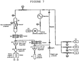
- the apparatus includes at least one reactor (30) with a configuration suitable for heterogeneous solid-catalyzed reactions.
- Carbon monoxide (31) and steam (32) required for the process are supplied to the reactor via feed lines equipped with flow controllers.
- the outlet of the reactor is connected to a discharge line provided with at least one cooler (34) and one gas-liquid separator (35) coupled to said cooler.
- the apparatus comprises an array of n successively positioned coolers (cooler 1 , cooler 2 , ..., cooler n ) each associated with a gas-liquid separator (gas-liquid separator 1 , gas-liquid separator 2 , ..., gas-liquid separator n , respectively).
- a gas-liquid separator gas-liquid separator 1 , gas-liquid separator 2 , ..., gas-liquid separator n , respectively.
- Non-condensable matter withdrawn from a gas-liquid separator is passed via a conduit to a cooler placed downstream to said gas-liquid separator (namely, cooler i+1 receives non-condensable materials from gas-liquid separator i ).
- Each of the gas-liquid separators is either directly or indirectly in fluid communication with a vessel for collecting an organic liquid, with at least one of the gas-liquid separators being connected to a liquid-liquid separator for carrying out a separation of a liquid mixture into its organic and aqueous components.
- the apparatus of Figure 7 comprises a first cooler (34) and a second cooler (36), each coupled to a gas-liquid separator, i.e., to a first gas-liquid separator (35) and a second gas-liquid separator (37), respectively, with either the first gas-liquid separator (35), the second gas-liquid separator (37) or both, being in fluid communication with a liquid-liquid separator (38) to enable the separation of a liquid mixture into organic and aqueous phases.
- a gas-liquid separator i.e., to a first gas-liquid separator (35) and a second gas-liquid separator (37), respectively, with either the first gas-liquid separator (35), the second gas-liquid separator (37) or both, being in fluid communication with a liquid-liquid separator (38) to enable the separation of a liquid mixture into organic and aqueous phases.
- the gaseous mixture produced at the reactor (30) is discharged.
- a first cooler (34) On cooling the mixture with the aid of a first cooler (34) to a temperature T 1 (T 1 >100°C) and condensation, a first gas-liquid mixture is formed, which is separated in (35) into a first liquid component and a first gaseous component.
- the first liquid component may consist of both aqueous and organic phases.
- the first liquid undergoes separation in a liquid-liquid separator (38) into organic and aqueous phases, following which the heavy organic compounds produced by the process are collected (39), e.g., linear alkanes and alkenes with 7-40 carbon atoms.
- This organic liquid constitutes the major product of the process and can be processed to give high-quality liquid fuels or chemicals by methods known in the art. Water may be also collected (in vessel (40) ).
- the first gaseous component discharged from (35) contains non-reacted CO, H 2 , and CO 2 with light organic compounds. It flows to a successively placed cooler (36). On further cooling to a temperature T 2 (T 2 ⁇ 10°C) in said second cooler (36), a second gas-liquid mixture is formed, which is separated in a second gas-liquid separator (37) into a second liquid component and a second gaseous component.
- the liquid component consists of an organic phase to be collected (in vessel (41) ).
- another aspect of the invention comprises a process for preparing liquid hydrocarbons, comprising contacting carbon monoxide-containing gas stream with steam in the presence of the potassium-promoted Fe 2+ (Fe 3+ y Al 3+ 1-y ) 2 O 4 , silica-containing pellets that were described above, and collecting the liquid hydrocarbons formed.
- the carbon monoxide-containing gaseous stream is not necessarily neat CO and may contain, in addition to carbon monoxide, also carbon dioxide up to molar fraction of 0.25, e.g., a feedstock consisting of CO:CO 2 mixture with a molar ratio of more than 3:1, e.g., more than 4:1, is perfectly acceptable: the experimental results reported below clearly show that the process of the invention runs swiftly in the presence of carbon dioxide in the feedstock material.
- the conversion of carbon monoxide to hydrocarbons is achieved without feeding a stream of hydrogen reactant to the reactor where the reaction takes place.
- the process contemplates the use of substantially hydrogen-free carbon monoxide-containing gaseous stream and steam.
- the inclusion of hydrogen is possible, for example, up to molar H 2 :CO of 0.25 and even up to 0.5 (as shown by (33) in Figure 7 ).
- the extrudates are used to catalyze the conversion of H 2 -lean syngas (H 2 /CO ⁇ 1) to hydrocarbons.
- the H 2 -lean syngas may be obtained by dry reforming of natural gas.
- Feed of the autothermal reforming process contains oxygen thus combustion also takes place: R4.
- Carbon dioxide is a greenhouse gas that poses environmental threats. Actually it could serve as a very useful source of carbon for production of fuels.
- Commercial facilities for CO 2 capture have been installed and advanced technologies for low-cost capture have been implemented. The major issue is how to integrate CO 2 into the production of liquid fuels and chemicals.
- One of the most viable routes is to replace the steam with CO 2 as the oxidation agent in the reforming of natural gas process called dry-reforming ( Yatish T. Shah and Todd H. Gardner, Catalysis Reviews: Science and Engineering, 56, 476-536, 2014 ): R5.
- CH 4 + CO 2 ⁇ 2CO + 2H 2 ⁇ H 298K 247 kJ/mole
- one aspect of the invention is a process for preparing liquid hydrocarbons, comprising converting carbon monoxide and hydrogen-containing gas stream with a molar ratio H 2 /CO ⁇ 1 to hydrocarbons in the presence of the potassium-promoted Fe 2+ (Fe 3+ y Al 3+ 1-y ) 2 O 4 , silica-containing pellets (extrudates) that were described above, and collecting the liquid hydrocarbons formed.
- the molar ratio H 2 /CO in the feed stream is in the range of 0.51 ⁇ H 2 /CO ⁇ 0.8 (for example, 0.6 ⁇ H 2/ CO ⁇ 0.8).
- the molar ratio H 2 /CO in the feed stream is in the range of 0.01 ⁇ H 2 /CO ⁇ 0.51 (for example 0.05 ⁇ H 2 /CO ⁇ 0.51 or 0.1 ⁇ H 2 /CO ⁇ 0.51), and water is added to the feed.
- the carbon monoxide and hydrogen-containing gas stream used as a feedstock may be H 2 -lean syngas obtained by dry reforming of natural gas.
- the invention relates to a process which comprises:
- the so-formed product hydrocarbons obtained in the second CO hydrogenation step may be upgraded by methods known in the art to produce liquid fuels and chemicals.
- a reactor with suitable configuration such as a packed bed reactor (see, for example, ST. C. TEUNER, P. NEUMANN and F. VON LINDE, The Calcor Standard and Calcor economy Processes, OIL GAS European Magazine 3/2001, 44-46 ; N.R. Udengaard, J.-H. Bak Hansen, D.C. Hanson, J.A. Stal, Sulfur Passivated Reforming Process Lowers Syngas H2/CO Ratio, Oil Gas J. 90 (10), (1992 ) 62).
- a feed stream consisting of the natural gas (chiefly methane) and carbon dioxide is supplied to the reactor.
- the ratio carbon dioxide to methane is CO 2 /CH 4 ⁇ 1. It is useful to keep this ratio above unity to achieve high stability of the catalyst by avoiding coke formation. Furthermore, the higher this ratio is, the higher the methane conversion and the lower the H 2 /CO obtained.
- the dry reforming reaction preferably takes place at a temperature between 700 and 1000°C, more preferably between 800 and 950°C, while the pressure is preferably from 1 to 40 atm.
- the hourly space velocity (WHSV) is not less than 20NL/g catalyst h -1 , preferably not less than 30NL/g catalyst h -1 and more preferably not less than 40NL/g catalyst h -1 .
- Catalysts suitable for promoting dry reforming of methane are known in the art.
- nickel-based catalysts on support, or catalysts based on noble metals can be used, such as those described by Guo et al., who reported that dry reforming of methane was successfully achieved over nickel catalysts supported on magnesium aluminate spinels [Applied Catalysis A: General 273, p. 75-82 (2004 )].
- Ni-substituted hexaaluminate catalyst with the general formula BaNi x Al 11-x O 19- ⁇ was prepared and used.
- the H 2 /CO ratio in the syngas can be decreased further to much lower values by separating water from the product and running the gaseous mixture through a commercial reverse water gas shift process.
- the composition of the syngas may be modified over the ratio range 0.01 ⁇ H 2 /CO ⁇ 1 by adding a reverse water gas shift process after dry reforming to reduce that ratio to the desired value, producing H 2 -lean syngas which can serve as a useful feedstock with the aid of a suitable catalyst, that is, the extrudates of the invention, as will now be described in detail.
- the conversion of the H 2 -lean syngas to hydrocarbons may take place in fixed-bed reactor, where the extrudates are placed (e.g., in an apparatus which is essentially similar to that shown in Figures 2 and 7 ).
- the H 2 -lean syngas stream is continuously fed to the reactor at weight WHSV of not less than 0.4h -1 , preferably not less than 0.5h -1 and more preferably not less than 0.6 h -1 .
- the reaction is carried out at a temperature in the range from 270 to 310°C at pressure of not less than 20 atmospheres, e.g., from 20 to 50.
- the feed may further contain water, depending on the composition of the H 2 -lean syngas.
- hydrocarbons obtained on converting H 2 -lean syngas with the aid of the catalysts described above can be upgraded, e.g., through catalytic processes under known conditions [ Arno de Klerk "Fischer-Tropsch fuels refinery design", Energy Environ. Sci., 2011, 4, 1177 ].
- the invention provides a process comprising dry reforming of natural gas with carbon dioxide to yield H 2 -lean syngas (H 2 /CO ⁇ 1), and converting said H 2 -lean syngas in the presence of a catalyst to hydrocarbons.
- the catalytically active compound was prepared by co-precipitation from an aqueous solution of Fe and Al nitrates, induced by the addition of aqueous ammonium hydroxide solution.
- 27.0 gram of Al(NO 3 ) 3 ⁇ 9H 2 O and 57.9 gram of Fe(NO 3 ) 3 ⁇ 9H 2 O were dissolved in 60 cm 3 of distilled water each.
- the solutions were then mixed together and the pH of the combined solution was adjusted to 8 by adding 250 cm 3 of aqueous NH 4 OH solution with concentration of ammonium hydroxide of 5 wt%.
- the obtained solid was filtered and washed with distilled water and further dried at 110°C for 24 hours.
- the atomic ratio of Fe:Al in the precipitating solution was 2:1.
- the obtained mixture was left for gelation overnight at room temperature.
- the obtained gel was formed into pellets by extrusion through a die with openings diameter of 2.5 mm, followed by cutting the extruded wire into extrudates with a length of 15 mm (a single-screw extruder was used).
- the extrudates were aged in air at room temperature for 24 hours.
- the aged extrudates were dried in air at 110°C for 6 hours followed by calcination in air at 350°C for period of 6 hours.
- No Fe 2 O 3 hematite phase was formed after calcination at 350°C.
- the calcined extrudates had diameter of 1.6 mm and length of 6-10 mm.
- An aqueous solution of K 2 CO 3 was added by incipient wetness impregnation.
- the solid was further dried in air at 110°C for 4 hours followed by calcination in air at 450°C for period of 3 h. No change in the shape and size of the extrudates was detected at the impregnation step.
- the catalytically active compound was prepared by co-precipitation from an aqueous solution of Fe and Al nitrates, induced by the addition of aqueous ammonium hydroxide solution.
- 27.0 gram of Al(NO 3 ) 3 ⁇ 9H 2 O and 57.9 gram of Fe (NO 3 ) 3 ⁇ 9H 2 O were dissolved in 60 cm 3 of distilled water each.
- the solutions were then mixed together and the pH of the combined solution was adjusted to 8 by adding 250 cm 3 of aqueous NH 4 OH solution with concentration of ammonium hydroxide of 5 wt%.
- the obtained solid was filtered and washed with distilled water and further dried at 110°C for 24 hours.
- the atomic ratio of Fe:Al in the precipitating solution was 2:1.
- SiO 2 precursor Lidox® HS-30
- the obtained mixture was mixed-kneaded in the hermetically closed kneader at temperature of 40°C for 5 h.
- the obtained gel was discharged from the kneader and formed into pellets by extrusion through a die with openings diameter of 2.5 mm, followed by cutting the extruded wire into extrudates with a length of 15 mm (a single-screw extruder was used).
- the extrudates were aged in air at room temperature for 24 hours.
- the aged extrudates were dried in air at 110°C for 6 hours followed by calcination in air at 350°C for period of 6 hours. No Fe 2 O 3 hematite phase was formed after calcination at 350°C.
- the calcined extrudates had diameter of 1.6 mm and length of 6-10 mm.
- An aqueous solution of K 2 CO 3 was added by incipient wetness impregnation.
- the solid was further dried in air at 110°C for 4 hours followed by calcination in air at 450°C for period of 3 h. No change in the shape and size of the extrudates was detected at the impregnation step.
- Example 1 In the set of experiments reported in Examples 3 to 5, the hydrogenation of carbon dioxide is illustrated.
- the extrudate of Example 1 and comparative catalysts were tested for their ability to advance the reaction of carbon dioxide with hydrogen to produce hydrocarbons.
- the reaction was carried out in the presence of binder-free granules consisting of the spinel Fe 2+ (Fe 3+ 0.47 Al 3+ 0.53 ) 2 O 4 which were produced by pressing the powdered catalyst in a press at a force of 10 tons, crushing and sieving the granules yielding a material with pellets size in the range 1.2-1.5 mm. Then, 3 g of these pellets (granules) were equally divided between the three reactors of the experimental set-up.
- binder-free granules consisting of the spinel Fe 2+ (Fe 3+ 0.47 Al 3+ 0.53 ) 2 O 4 which were produced by pressing the powdered catalyst in a press at a force of 10 tons, crushing and sieving the granules yielding a material with pellets size in the range 1.2-1.5 mm.
- the catalytically active material was employed in the form of alumina-containing pellets, prepared as described in Example 29 of WO 2014/111919 (consisting of 66.6% Fe 2+ (Fe 3+ 0.47 Al 3+ 0.53 ) 2 O 4 , 24.2% Al 2 O 3 and 9.2% K; 3% K was inserted before addition of Al 2 O 3 , the rest - after calcination of Al 2 O 3 -containing extrudates). Then, 3 g of these pellets were equally divided between the three reactors in the experimental set-up.
- reaction products were cooled down to +4°C and separated in cooled (+4°C) container.
- Gas products were analyzed in online Agilent 7890A Series Gas Chromatograph equipped with 7 columns and 5 automatic valves using helium as a carrier gas. Liquid products were separated into aqueous and organic phases. Aqueous phase was analyzed for Total Organic Carbon in Shimadzu TOC-V CPN Analyzer.
- Example 1 In the set of experiments reported in Examples 7 to 9, the extrudates of Example 1 was tested for its ability to advance the reaction of carbon monoxide with steam to produce hydrocarbons according to the following conditions.
- CO reaction with steam was then conducted by passing a mixture of steam and CO streams ((1) and (2), respectively) at a molar ratio 0.35:1 through a tubular reactor (3) (16 mm ID, 250 mm long) packed with 12 gram of the extrudates of Example 1 and heated up to 280°C at a total pressure of 30 atm. Steam is produced by vaporizing water stream in a vaporizer (10). All gaseous reactants are fed via feed line (13) to the reactor (3) .
- reaction products were cooled down to a temperature T 1 (T 1 >100°C) to form a first mixture consisting of non-condensable and liquid products.
- the first mixture is separated in a first gas-liquid separator (5A) into a first liquid component and a first gaseous component.
- the first liquid component obtained under the experimental conditions consists of organic and aqueous phases.
- the first liquid is therefore separated in a liquid-liquid separator (6) into organic and aqueous phases, which are collected in vessels (7A) and (8), respectively.
- the first gaseous component is cooled down with the aid of a second cooler (4B) to a temperature T 2 (T 2 ⁇ 10°C), undergoing condensation to form a second mixture consisting of non-condensable materials and liquid products.
- the second mixture is then separated in a second gas-liquid separator (5B) into a second liquid component and a second gaseous component.
- the second liquid component consisting of light organic products, is collected in a vessel (7B).
- the non-condensable components (9) consist of CO 2 , CO, light hydrocarbons and residual H 2 generated by the water gas shift reaction.
- Gas products (9) were analyzed in online Agilent 7890A Series Gas Chromatograph equipped with 7 columns and 5 automatic valves using helium as a carrier gas.
- the distillation patterns of the hydrocarbon oil produced were estimated by simulated distillation method based on the maximal boiling points of components in 10 vol% oil fractions.
- W cat is weight of catalyst (gram) loaded into reactor
- X and S stand for conversion and selectivity, respectively.
- composition of the liquid product is shown in Figure 3 in the form of a bar diagram.
- the composition of the liquid product is shown in Figure 4 in the form of a bar diagram.
- the simulated distillation curve of products is depicted in Figure 5 .
- Example 10 shows the generation of H 2 -lean syngas by dry reforming of natural gas with carbon dioxide with the aid of Ni-containing catalyst (the synthesis of the Ni-containing catalyst is shown in Preparation 1 below). Then, in Examples 11 to 13, the extrudates of Example 1 and 2 according to the invention and comparative extrudates are tested for their ability to advance the conversion of H 2 -lean syngas into hydrocarbons.
- Dry reforming Carbon dioxide reaction with methane in a fixed bed reactor
- FIG. 6 A schematic description of the experimental set-up is shown in Figure 6 .
- the catalytic performance of the dry reforming (DR) catalyst (Ni-haxaaluminateBaNiAl 11 O 19- ⁇ of Preparation 1) was measured in stainless steel (0.95 cm I.D.) fixed bed reactor (21) with a central tube (0.31 cm O.D.) equipped with a movable thermocouple for measuring the axial temperature profile.
- the reactor is heated at the wall by a high temperature electrical heater.
- the reactor was packed with powder catalyst diluted with SiC powder of ring shape catalyst.
- Each gaseous reactant flows from cylinders (22) and its rate is controlled by an electronic mass flow controller (FC) (Brooks Co.).
- FC electronic mass flow controller
- Feed and effluent streams were analyzed with an Agilent 7890A GC (GC) equipped with FID and TCD detectors and IR analyzer. Water was condensed (23) from the products gas stream using a cold trap (24) at the outlet of the reactor.
- GC Agilent 7890A GC
- the BaNiAl 11 O 19- ⁇ catalyst of Preparation 1 was used to promote the reaction of methane with carbon dioxide, to produce H 2 -lean syngas.
- 0.2g of the catalyst of Preparation 1 in powdered form (106-150 ⁇ m) diluted with 0.2g SiO 2 was loaded into the reactor.
- a gas mixture containing CH 4 and CO 2 was fed to the reactor.
- the catalyst was reduced at 900°C for 1h in a 60%H 2 -40%N 2 mixture flow.
- the dry reforming of methane was conducted with the catalyst described in Preparation 1 at atmospheric pressure and 870°C.
- the feed was composed of 66 mol% CO 2 and 34 mol% CH 4 .
- CO was contacted with H 2 and optionally with steam by passing a mixture of CO, H 2 and optionally H 2 O streams (indicated by numerals (2), (11) and (1) , respectively) through a tubular reactor (3) (16 mm ID, 250 mm long) packed with 12 gram of the extrudates of the invention and heated up to 280°C at a total pressure of 30 atm. Steam is produced by vaporizing water stream in a vaporizer (10) . All gaseous reactants are fed via line (13) to the reactor (3).
- reaction products were cooled down to a temperature T 1 (T 1 >100°C) to form a first mixture consisting of non-condensable and liquid products.
- the first mixture is separated in a first gas-liquid separator (5A) into a first liquid component and a first gaseous component.
- the first liquid component obtained under the experimental conditions consists of organic and aqueous phases.
- the first liquid is therefore separated in a liquid-liquid separator (6) into organic and aqueous phases, which are collected in vessels (7A) and (8), respectively.
- the first gaseous component is cooled down with the aid of a second cooler (4B) to a temperature T 2 (T 2 ⁇ 10°C), undergoing condensation to form a second mixture consisting of non-condensable materials and liquid products.
- the second mixture is then separated in a second gas-liquid separator (5B) into a second liquid component and a second gaseous component.
- the second liquid component consisting of light organic products, is collected in a vessel (7B).
- the non-condensable components (9) consist of CO 2 , CO, light hydrocarbons and residual H 2 generated by the water gas shift reaction.
- Example 13 a comparative catalyst prepared as described in Preparation 2 was tested for its ability to advance the reaction of carbon monoxide with hydrogen to produce hydrocarbons.
- the resulting solution was then poured at 60°C with vigorous stirring into an aqueous solution containing a large excess of (NH 4 ) 2 CO 3 to form the hexaaluminate precursor precipitate. During the precipitation, a large amount of CO 2 was released while the pH value of the solution was maintained between 7.5 and 8.0.
- the resulting slurry was aged with continuous stirring at 60°C for 3h followed by filtration and washing with deionized water. The obtained cake was then dried at 110°C in air overnight. The powder was further calcined at 500°C for 2 h, followed by calcination at 1300°C and 1400°C for 3-5 h.
- the resulting powder was crushed and sieved to collect the fraction smaller than 160 ⁇ m.
- XRD analysis yielded the following phases: Ba 0.69 Ni 0.48 Al 6.36 O 11 - 95%, ⁇ -Al 2 O 3 -5%.
- the BET surface area is 12 cm 2 /g.
- the obtained gel was formed into pellets by extrusion through a die with openings diameter of 1.8 mm, followed by cutting the extruded wire in pellets with the length of 15 mm.
- the extrudates were aged in air at room temperature for 24 hours.
- the aged extrudates were dried in air at 110°C for 6 hours followed by calcination in air at 300°C for period of 3 hours.
- the calcined extrudates had diameter of 1.6 mm and length of 6-10 mm.
- An aqueous solution of KHCO 3 was added by incipient wetness impregnation at amount yielding 4 wt.% K in extrudates.
- the solid was further dried in air at 110°C for 8 hours followed by calcination in air at 300°C for period of 6 h. No change in the shape and size of the pellets was detected at the impregnation step.
Landscapes
- Chemical & Material Sciences (AREA)
- Engineering & Computer Science (AREA)
- Chemical Kinetics & Catalysis (AREA)
- Organic Chemistry (AREA)
- Materials Engineering (AREA)
- Oil, Petroleum & Natural Gas (AREA)
- General Chemical & Material Sciences (AREA)
- Physics & Mathematics (AREA)
- Thermal Sciences (AREA)
- Catalysts (AREA)
- Organic Low-Molecular-Weight Compounds And Preparation Thereof (AREA)
- Nanotechnology (AREA)
- Low-Molecular Organic Synthesis Reactions Using Catalysts (AREA)
Claims (15)
- Verfahren zur Herstellung kaliumveredelter Fe2+(Fe3+ yAl3+ 1-y)2O4 [0,3≤y≤0,7] kieselsäurehaltiger Pellets, umfassend das Aussetzen kolloidaler Kieselsäure einer Gelbildung in der Gegenwart von Fe2+(Fe3+ yAl3+ 1-y)2O4 Spinellpartikeln, Umwandeln des gelierten Materiales in Pellets und Zugeben von Kalium zu den Pellets.
- Verfahren nach Anspruch 1, wobei die verwendete kolloidale Kieselsäure eine wässrige alkalistabilisierte kolloidale Kieselsäure ist, umfassend amorphe Kieselsäure mit einer Partikelgröße von bis zu 50 nm.
- Verfahren nach irgendeinem der Ansprüche 1 oder 2, wobei das verwendete Fe2+(Fe3+ yAl3+ 1-y)2O4 Spinell in der Form eines Pulvers mit einer Partikelgröße von weniger als 250 µm ist, bestimmt per Laserbeugung.
- Verfahren nach irgendeinem der vorherigen Ansprüche, wobei die kaliumveredelten Fe2+(Fe3+ yAl3+ 1-y)2O4 kieselsäurehaltigen Pellets kaliumveredelte Fe2+(Fe3+ yAl3+ 1-y)2O4 kieselsäurehaltige Extrudate sind.
- Verfahren nach Anspruch 4, umfassend:(i) Senken des pH einer wässrigen alkalistabilisierten kolloidalen Kieselsäure;(ii) Vereinen der kolloidalen Kieselsäure mit Fe2+(Fe3+ yAl3+ 1-y)2O4 Spinellpartikeln;(iii) Erlauben der aus Schritt (ii) resultierenden Mischung, sich in ein Gel umzubilden;(iv) Anpassen der Konsistenz des Geles, um eine extrudierbare Masse zu erhalten;(v) Extrudieren der Masse, um Extrudate zu bilden;(vi) Trocknen der Extrudate;(vii) Calcinieren der getrockneten Extrudate;(viii) Behandeln der calcinierten Extrudate mit einer wässrigen Lösung eines Kaliumsalzes;(ix) Trocknen der kaliumhaltigen Extrudate, die aus Schritt (viii) resultieren; und(x) Calcinieren der Extrudate, die aus Schritt (ix) resultieren.
- Verfahren nach Anspruch 5, wobei in Schritt (i) eine Säure zu der wässrigen alkalistabilisierten kolloidalen Kieselsäure gegeben wird, um den pH in den Bereich von 6,5 bis 7,5 abzusenken.
- Kaliumveredelte Fe2+(Fe3+ yAl3+ 1-y)2O4[0,3≤y≤0,7] kieselsäurehaltige Extrudate.
- Kaliumveredelte Fe2+(Fe3+ yAl3+ 1-y)2O4 [0,3≤y≤0,7] kieselsäurehaltige Extrudate nach Anspruch 7, bestehend aus 45 bis 85 Gew.-% Fe2+(Fe3+ yAl3+ 1-y)2O4, 10-50 Gew.-% SiO2 und 3 bis 10 Gew.-% Kalium.
- Verwendung der Extrudate nach Anspruch 7 oder 8 bei der Hydrierung eines kohlenstoffdioxidhaltigen Gasstromes zur Herstellung von Kohlenwasserstoffen in der Gegenwart der Extrudate.
- Verwendung der Extrudate nach Anspruch 7 oder 8 bei der Reaktion eines kohlenstoffmonoxidhaltigen Gasstromes mit Dampf zur Herstellung von Kohlenwasserstoffen in der Gegenwart der Extrudate.
- Verwendung nach Anspruch 10, wobei der kohlenstoffmonoxidhaltige Gasstrom eine Mischung von CO2 und CO umfasst, mit einem molaren Verhältnis CO2:CO von weniger als 0,25:1.
- Verwendung der Extrudate nach Anspruch 7 oder 8 zum Umwandeln eines kohlenstoffmonoxid- und wasserstoffhaltigen Gasstromes mit einem molaren Verhältnis H2/CO ≤ 1 zu Kohlenwasserstoffen in der Gegenwart der Extrudate.
- Verwendung nach Anspruch 12, wobei der kohlenstoffmonoxid- und wasserstoffhaltige Gasstrom ein molares Verhältnis 0,51<H2/CO<0,8 aufweist.
- Verwendung nach Anspruch 12, wobei der kohlenstoffmonoxid- und wasserstoffhaltige Gasstrom ein molares Verhältnis 0,01<H2/CO<0,51 aufweist und mit Dampf in der Gegenwart der Extrudate definiert in Anspruch 7 oder 8 vermischt wird.
- Verwendung nach irgendeinem der Ansprüche 12 bis 14, wobei der kohlenstoffmonoxid- und wasserstoffhaltige Gasstrom, der als Rohstoff verwendet wird, H2-armes Synthesegas (H2/CO≤1) ist, das aus trockenem Reforming von natürlichem Gas mit Kohlenstoffdioxid erhalten wird.
Applications Claiming Priority (4)
| Application Number | Priority Date | Filing Date | Title |
|---|---|---|---|
| US201562143834P | 2015-04-07 | 2015-04-07 | |
| US201562143838P | 2015-04-07 | 2015-04-07 | |
| US201562188669P | 2015-07-05 | 2015-07-05 | |
| PCT/IL2016/050364 WO2016162866A1 (en) | 2015-04-07 | 2016-04-06 | Catalyst composition and catalytic processes for producing liquid hydrocarbons |
Publications (3)
| Publication Number | Publication Date |
|---|---|
| EP3280529A1 EP3280529A1 (de) | 2018-02-14 |
| EP3280529A4 EP3280529A4 (de) | 2018-09-26 |
| EP3280529B1 true EP3280529B1 (de) | 2020-01-29 |
Family
ID=57072231
Family Applications (1)
| Application Number | Title | Priority Date | Filing Date |
|---|---|---|---|
| EP16776222.8A Active EP3280529B1 (de) | 2015-04-07 | 2016-04-06 | Katalysatorzusammensetzung, deren verwendung, und katalytische verfahren zur herstellung von flüssigen kohlenwasserstoffen |
Country Status (6)
| Country | Link |
|---|---|
| US (2) | US10589257B2 (de) |
| EP (1) | EP3280529B1 (de) |
| AU (1) | AU2016245430B2 (de) |
| CA (1) | CA2978832C (de) |
| IL (1) | IL254524B (de) |
| WO (1) | WO2016162866A1 (de) |
Families Citing this family (7)
| Publication number | Priority date | Publication date | Assignee | Title |
|---|---|---|---|---|
| WO2018051334A1 (en) * | 2016-09-19 | 2018-03-22 | B.G. Negev Technologies And Applications Ltd., At Ben-Gurion University | Novel, highly efficient eco-friendly processes for converting co2 or co-rich streams to liquid fuels and chemicals |
| US10906808B2 (en) | 2017-11-15 | 2021-02-02 | Gas Technology Institute | Noble metal catalysts and processes for reforming of methane and other hydrocarbons |
| WO2020002326A1 (en) | 2018-06-29 | 2020-01-02 | Shell Internationale Research Maatschappij B.V. | Electrically heated reactor and a process for gas conversions using said reactor |
| US12122962B2 (en) | 2018-09-18 | 2024-10-22 | Gti Energy | Processes and catalysts for reforming of impure methane-containing feeds |
| ZA202006924B (en) * | 2019-11-11 | 2021-09-29 | Indian Oil Corp Ltd | A process for producing hydrogen and light olefins from resid fluid catalytic cracking |
| CA3164121A1 (en) | 2019-12-23 | 2021-07-01 | Shell Internationale Research Maatschappij B.V. | Electrically heated reactor, a furnace comprising said reactor and a method for gas conversions using said reactor |
| US12565423B2 (en) | 2023-01-26 | 2026-03-03 | Valero Services, Inc. | Process for producing hydrogen from natural gas |
Family Cites Families (8)
| Publication number | Priority date | Publication date | Assignee | Title |
|---|---|---|---|---|
| US4565831A (en) | 1981-12-16 | 1986-01-21 | Exxon Research And Engineering Co. | Process for producing aromatic hydrocarbons from carbon monoxide and water |
| US4582815A (en) | 1984-07-06 | 1986-04-15 | Mobil Oil Corporation | Extrusion of silica-rich solids |
| US4559363A (en) | 1984-08-17 | 1985-12-17 | Standard Oil Company (Indiana) | Process for reacting carbon monoxide and water |
| US5053374A (en) | 1987-05-01 | 1991-10-01 | Mobil Oil Corporation | Method for preparing a zeolite catalyst bound with a refractory oxide of low acidity |
| FR2694013B1 (fr) * | 1992-07-27 | 1994-09-30 | Inst Francais Du Petrole | Catalyseur à base de cobalt et procédé de conversion du gaz de synthèse en hydrocarbures. |
| DE602004027388D1 (de) * | 2004-11-10 | 2010-07-08 | Res Inst Petroleum Industry | Verfahren zur Herstellung von Benzin aus Synthesegas mit einem Schritt der Regeneration von Katalysator |
| US7915193B2 (en) | 2007-08-30 | 2011-03-29 | Rentech, Inc. | Method for activating strengthened iron catalyst for slurry reactors |
| EP2945920B1 (de) * | 2013-01-17 | 2020-08-05 | B.G. Negev Technologies and Applications Ltd. | Katalysator und verfahren zur katalytischen umsetzung eines kohlendioxidhaltigen gases und von wasserstoffströmen zu kohlenwasserstoffen |
-
2016
- 2016-04-06 WO PCT/IL2016/050364 patent/WO2016162866A1/en not_active Ceased
- 2016-04-06 AU AU2016245430A patent/AU2016245430B2/en active Active
- 2016-04-06 US US15/563,700 patent/US10589257B2/en active Active
- 2016-04-06 EP EP16776222.8A patent/EP3280529B1/de active Active
- 2016-04-06 CA CA2978832A patent/CA2978832C/en active Active
-
2017
- 2017-09-17 IL IL254524A patent/IL254524B/en unknown
-
2019
- 2019-10-08 US US16/596,398 patent/US20200038844A1/en not_active Abandoned
Non-Patent Citations (1)
| Title |
|---|
| NAKHAEI POUR ALI ET AL: "Study of activity, products selectivity and physico-chemical properties of bifunctional Fe/HZSM-5 Fischer-Tropsch catalyst: Effect of catalyst sha", JOURNAL OF NATURAL GAS SCIENCE AND ENGINEERING, ELSEVIER, AMSTERDAM, NL, vol. 14, 28 May 2013 (2013-05-28), pages 29 - 33, XP028703208, ISSN: 1875-5100, DOI: 10.1016/J.JNGSE.2013.04.004 * |
Also Published As
| Publication number | Publication date |
|---|---|
| US20180078923A1 (en) | 2018-03-22 |
| CA2978832C (en) | 2023-03-14 |
| EP3280529A1 (de) | 2018-02-14 |
| WO2016162866A1 (en) | 2016-10-13 |
| EP3280529A4 (de) | 2018-09-26 |
| US10589257B2 (en) | 2020-03-17 |
| IL254524B (en) | 2022-05-01 |
| US20200038844A1 (en) | 2020-02-06 |
| CA2978832A1 (en) | 2016-10-13 |
| IL254524A0 (en) | 2017-11-30 |
| AU2016245430A1 (en) | 2017-09-28 |
| AU2016245430B2 (en) | 2020-07-30 |
Similar Documents
| Publication | Publication Date | Title |
|---|---|---|
| EP3280529B1 (de) | Katalysatorzusammensetzung, deren verwendung, und katalytische verfahren zur herstellung von flüssigen kohlenwasserstoffen | |
| EP2152409B1 (de) | Katalytische hydrierung von kohlendioxid zu einem syngas-gemisch | |
| Carvalho et al. | Bio-ethanol steam reforming for hydrogen production over Co3O4/CeO2 catalysts synthesized by one-step polymerization method | |
| Harun et al. | Hydrogen production from glycerol dry reforming over Ag-promoted Ni/Al2O3 | |
| EP3515882B1 (de) | Neuartige, hocheffiziente umweltfreundliche verfahren zur umwandlung von co2- oder co-reichen strömen in flüssige kraftstoffe und chemikalien | |
| Turco et al. | Cu/ZnO/Al2O3 catalysts for oxidative steam reforming of methanol: the role of Cu and the dispersing oxide matrix | |
| Sharifi et al. | Hydrogen production via reforming of biogas over nanostructured Ni/Y catalyst: Effect of ultrasound irradiation and Ni-content on catalyst properties and performance | |
| AU2015203898B2 (en) | A catalyst and a process for catalytic conversion of carbon dioxide-containing gas and hydrogen streams to hydrocarbons | |
| US9522386B2 (en) | Catalyst and a process for catalytic conversion of carbon dioxide-containing gas and hydrogen streams to hydrocarbons | |
| EP2675561A1 (de) | Katalysatoren zur verwendung in dampfreformierungsprozessen | |
| Habibi et al. | CH4 reforming with CO2 for syngas production over La2O3 promoted Ni catalysts supported on mesoporous nanostructured γ-Al2O3 | |
| WO2017051284A1 (en) | Mixed metal oxide catalysts for direct co2 hydrogenation to methanol | |
| EP4349484A1 (de) | Verfahren zur herstellung eines zweidimensionalen nickelsilikat-molekularsiebkatalysators zur trockenreformierung von methan | |
| WO2025096928A1 (en) | Reduction catalysts, properties thereof, and methods of making and using the same | |
| EP2945920B1 (de) | Katalysator und verfahren zur katalytischen umsetzung eines kohlendioxidhaltigen gases und von wasserstoffströmen zu kohlenwasserstoffen | |
| Sun et al. | Direct coating copper–zinc–aluminum oxalate with H-ZSM-5 to fabricate a highly efficient capsule-structured bifunctional catalyst for dimethyl ether production from syngas | |
| Mesrar et al. | Hydrogen production on Ni loaded apatite-like oxide synthesized by dissolution-precipitation of natural phosphate | |
| Pour et al. | THE INFLUENCE OF La2O3 and TiO2on NiO/MgO/α-Al2O3 | |
| Lv et al. | Catalyst and process for the synthesis of piperidine via reductive amination from biomass derivative δ-valerolactone | |
| WO2018015827A1 (en) | Process for high-pressure hydrogenation of carbon dioxide to syngas in the presence of copper-manganese-aluminum mixed metal oxide catalysts | |
| CA3036635C (en) | Highly efficient, eco-friendly processes for converting co2 or co-rich streams to liquid fuels and chemicals | |
| Nakhaei Pour et al. | The influence of La2O3 and TiO2 on NiO/MgO/α-Al2O3 | |
| OA21621A (en) | Production of liquefied petroleum gas (LPG) hydrocarbons from carbon dioxidecontaining feeds. | |
| WO2018051198A1 (en) | Process for high-pressure hydrogenation of carbon dioxide to syngas and methane using copper-manganese-aluminum mixed metal oxide catalysts |
Legal Events
| Date | Code | Title | Description |
|---|---|---|---|
| STAA | Information on the status of an ep patent application or granted ep patent |
Free format text: STATUS: THE INTERNATIONAL PUBLICATION HAS BEEN MADE |
|
| PUAI | Public reference made under article 153(3) epc to a published international application that has entered the european phase |
Free format text: ORIGINAL CODE: 0009012 |
|
| STAA | Information on the status of an ep patent application or granted ep patent |
Free format text: STATUS: REQUEST FOR EXAMINATION WAS MADE |
|
| 17P | Request for examination filed |
Effective date: 20170926 |
|
| AK | Designated contracting states |
Kind code of ref document: A1 Designated state(s): AL AT BE BG CH CY CZ DE DK EE ES FI FR GB GR HR HU IE IS IT LI LT LU LV MC MK MT NL NO PL PT RO RS SE SI SK SM TR |
|
| AX | Request for extension of the european patent |
Extension state: BA ME |
|
| DAV | Request for validation of the european patent (deleted) | ||
| DAX | Request for extension of the european patent (deleted) | ||
| A4 | Supplementary search report drawn up and despatched |
Effective date: 20180827 |
|
| RIC1 | Information provided on ipc code assigned before grant |
Ipc: C10G 2/00 20060101ALI20180821BHEP Ipc: B01J 23/00 20060101AFI20180821BHEP Ipc: B01J 37/00 20060101ALI20180821BHEP |
|
| REG | Reference to a national code |
Ref country code: DE Ref legal event code: R079 Ref document number: 602016028806 Country of ref document: DE Free format text: PREVIOUS MAIN CLASS: B01J0023000000 Ipc: B01J0037080000 |
|
| RIC1 | Information provided on ipc code assigned before grant |
Ipc: C10G 2/00 20060101ALI20190718BHEP Ipc: B01J 35/10 20060101ALI20190718BHEP Ipc: B01J 37/08 20060101AFI20190718BHEP Ipc: B01J 23/78 20060101ALI20190718BHEP Ipc: B01J 37/18 20060101ALI20190718BHEP Ipc: B01J 37/03 20060101ALI20190718BHEP Ipc: B01J 23/00 20060101ALI20190718BHEP Ipc: B01J 23/02 20060101ALI20190718BHEP Ipc: B01J 23/745 20060101ALI20190718BHEP Ipc: B01J 37/00 20060101ALI20190718BHEP Ipc: B01J 35/02 20060101ALI20190718BHEP |
|
| GRAP | Despatch of communication of intention to grant a patent |
Free format text: ORIGINAL CODE: EPIDOSNIGR1 |
|
| STAA | Information on the status of an ep patent application or granted ep patent |
Free format text: STATUS: GRANT OF PATENT IS INTENDED |
|
| INTG | Intention to grant announced |
Effective date: 20190826 |
|
| GRAS | Grant fee paid |
Free format text: ORIGINAL CODE: EPIDOSNIGR3 |
|
| GRAA | (expected) grant |
Free format text: ORIGINAL CODE: 0009210 |
|
| STAA | Information on the status of an ep patent application or granted ep patent |
Free format text: STATUS: THE PATENT HAS BEEN GRANTED |
|
| AK | Designated contracting states |
Kind code of ref document: B1 Designated state(s): AL AT BE BG CH CY CZ DE DK EE ES FI FR GB GR HR HU IE IS IT LI LT LU LV MC MK MT NL NO PL PT RO RS SE SI SK SM TR |
|
| REG | Reference to a national code |
Ref country code: GB Ref legal event code: FG4D |
|
| REG | Reference to a national code |
Ref country code: CH Ref legal event code: EP |
|
| REG | Reference to a national code |
Ref country code: AT Ref legal event code: REF Ref document number: 1228094 Country of ref document: AT Kind code of ref document: T Effective date: 20200215 |
|
| REG | Reference to a national code |
Ref country code: IE Ref legal event code: FG4D |
|
| REG | Reference to a national code |
Ref country code: DE Ref legal event code: R096 Ref document number: 602016028806 Country of ref document: DE |
|
| REG | Reference to a national code |
Ref country code: NL Ref legal event code: MP Effective date: 20200129 |
|
| PG25 | Lapsed in a contracting state [announced via postgrant information from national office to epo] |
Ref country code: PT Free format text: LAPSE BECAUSE OF FAILURE TO SUBMIT A TRANSLATION OF THE DESCRIPTION OR TO PAY THE FEE WITHIN THE PRESCRIBED TIME-LIMIT Effective date: 20200621 Ref country code: RS Free format text: LAPSE BECAUSE OF FAILURE TO SUBMIT A TRANSLATION OF THE DESCRIPTION OR TO PAY THE FEE WITHIN THE PRESCRIBED TIME-LIMIT Effective date: 20200129 Ref country code: NO Free format text: LAPSE BECAUSE OF FAILURE TO SUBMIT A TRANSLATION OF THE DESCRIPTION OR TO PAY THE FEE WITHIN THE PRESCRIBED TIME-LIMIT Effective date: 20200429 Ref country code: FI Free format text: LAPSE BECAUSE OF FAILURE TO SUBMIT A TRANSLATION OF THE DESCRIPTION OR TO PAY THE FEE WITHIN THE PRESCRIBED TIME-LIMIT Effective date: 20200129 |
|
| REG | Reference to a national code |
Ref country code: LT Ref legal event code: MG4D |
|
| PG25 | Lapsed in a contracting state [announced via postgrant information from national office to epo] |
Ref country code: IS Free format text: LAPSE BECAUSE OF FAILURE TO SUBMIT A TRANSLATION OF THE DESCRIPTION OR TO PAY THE FEE WITHIN THE PRESCRIBED TIME-LIMIT Effective date: 20200529 Ref country code: BG Free format text: LAPSE BECAUSE OF FAILURE TO SUBMIT A TRANSLATION OF THE DESCRIPTION OR TO PAY THE FEE WITHIN THE PRESCRIBED TIME-LIMIT Effective date: 20200429 Ref country code: LV Free format text: LAPSE BECAUSE OF FAILURE TO SUBMIT A TRANSLATION OF THE DESCRIPTION OR TO PAY THE FEE WITHIN THE PRESCRIBED TIME-LIMIT Effective date: 20200129 Ref country code: SE Free format text: LAPSE BECAUSE OF FAILURE TO SUBMIT A TRANSLATION OF THE DESCRIPTION OR TO PAY THE FEE WITHIN THE PRESCRIBED TIME-LIMIT Effective date: 20200129 Ref country code: HR Free format text: LAPSE BECAUSE OF FAILURE TO SUBMIT A TRANSLATION OF THE DESCRIPTION OR TO PAY THE FEE WITHIN THE PRESCRIBED TIME-LIMIT Effective date: 20200129 Ref country code: GR Free format text: LAPSE BECAUSE OF FAILURE TO SUBMIT A TRANSLATION OF THE DESCRIPTION OR TO PAY THE FEE WITHIN THE PRESCRIBED TIME-LIMIT Effective date: 20200430 |
|
| PG25 | Lapsed in a contracting state [announced via postgrant information from national office to epo] |
Ref country code: NL Free format text: LAPSE BECAUSE OF FAILURE TO SUBMIT A TRANSLATION OF THE DESCRIPTION OR TO PAY THE FEE WITHIN THE PRESCRIBED TIME-LIMIT Effective date: 20200129 |
|
| PG25 | Lapsed in a contracting state [announced via postgrant information from national office to epo] |
Ref country code: DK Free format text: LAPSE BECAUSE OF FAILURE TO SUBMIT A TRANSLATION OF THE DESCRIPTION OR TO PAY THE FEE WITHIN THE PRESCRIBED TIME-LIMIT Effective date: 20200129 Ref country code: ES Free format text: LAPSE BECAUSE OF FAILURE TO SUBMIT A TRANSLATION OF THE DESCRIPTION OR TO PAY THE FEE WITHIN THE PRESCRIBED TIME-LIMIT Effective date: 20200129 Ref country code: EE Free format text: LAPSE BECAUSE OF FAILURE TO SUBMIT A TRANSLATION OF THE DESCRIPTION OR TO PAY THE FEE WITHIN THE PRESCRIBED TIME-LIMIT Effective date: 20200129 Ref country code: LT Free format text: LAPSE BECAUSE OF FAILURE TO SUBMIT A TRANSLATION OF THE DESCRIPTION OR TO PAY THE FEE WITHIN THE PRESCRIBED TIME-LIMIT Effective date: 20200129 Ref country code: SM Free format text: LAPSE BECAUSE OF FAILURE TO SUBMIT A TRANSLATION OF THE DESCRIPTION OR TO PAY THE FEE WITHIN THE PRESCRIBED TIME-LIMIT Effective date: 20200129 Ref country code: CZ Free format text: LAPSE BECAUSE OF FAILURE TO SUBMIT A TRANSLATION OF THE DESCRIPTION OR TO PAY THE FEE WITHIN THE PRESCRIBED TIME-LIMIT Effective date: 20200129 Ref country code: SK Free format text: LAPSE BECAUSE OF FAILURE TO SUBMIT A TRANSLATION OF THE DESCRIPTION OR TO PAY THE FEE WITHIN THE PRESCRIBED TIME-LIMIT Effective date: 20200129 Ref country code: RO Free format text: LAPSE BECAUSE OF FAILURE TO SUBMIT A TRANSLATION OF THE DESCRIPTION OR TO PAY THE FEE WITHIN THE PRESCRIBED TIME-LIMIT Effective date: 20200129 |
|
| REG | Reference to a national code |
Ref country code: DE Ref legal event code: R097 Ref document number: 602016028806 Country of ref document: DE |
|
| REG | Reference to a national code |
Ref country code: AT Ref legal event code: MK05 Ref document number: 1228094 Country of ref document: AT Kind code of ref document: T Effective date: 20200129 |
|
| PG25 | Lapsed in a contracting state [announced via postgrant information from national office to epo] |
Ref country code: MC Free format text: LAPSE BECAUSE OF FAILURE TO SUBMIT A TRANSLATION OF THE DESCRIPTION OR TO PAY THE FEE WITHIN THE PRESCRIBED TIME-LIMIT Effective date: 20200129 |
|
| REG | Reference to a national code |
Ref country code: CH Ref legal event code: PL |
|
| PLBE | No opposition filed within time limit |
Free format text: ORIGINAL CODE: 0009261 |
|
| STAA | Information on the status of an ep patent application or granted ep patent |
Free format text: STATUS: NO OPPOSITION FILED WITHIN TIME LIMIT |
|
| 26N | No opposition filed |
Effective date: 20201030 |
|
| PG25 | Lapsed in a contracting state [announced via postgrant information from national office to epo] |
Ref country code: CH Free format text: LAPSE BECAUSE OF NON-PAYMENT OF DUE FEES Effective date: 20200430 Ref country code: LU Free format text: LAPSE BECAUSE OF NON-PAYMENT OF DUE FEES Effective date: 20200406 Ref country code: IT Free format text: LAPSE BECAUSE OF FAILURE TO SUBMIT A TRANSLATION OF THE DESCRIPTION OR TO PAY THE FEE WITHIN THE PRESCRIBED TIME-LIMIT Effective date: 20200129 Ref country code: AT Free format text: LAPSE BECAUSE OF FAILURE TO SUBMIT A TRANSLATION OF THE DESCRIPTION OR TO PAY THE FEE WITHIN THE PRESCRIBED TIME-LIMIT Effective date: 20200129 Ref country code: LI Free format text: LAPSE BECAUSE OF NON-PAYMENT OF DUE FEES Effective date: 20200430 |
|
| REG | Reference to a national code |
Ref country code: BE Ref legal event code: MM Effective date: 20200430 |
|
| PG25 | Lapsed in a contracting state [announced via postgrant information from national office to epo] |
Ref country code: PL Free format text: LAPSE BECAUSE OF FAILURE TO SUBMIT A TRANSLATION OF THE DESCRIPTION OR TO PAY THE FEE WITHIN THE PRESCRIBED TIME-LIMIT Effective date: 20200129 Ref country code: BE Free format text: LAPSE BECAUSE OF NON-PAYMENT OF DUE FEES Effective date: 20200430 Ref country code: SI Free format text: LAPSE BECAUSE OF FAILURE TO SUBMIT A TRANSLATION OF THE DESCRIPTION OR TO PAY THE FEE WITHIN THE PRESCRIBED TIME-LIMIT Effective date: 20200129 |
|
| PG25 | Lapsed in a contracting state [announced via postgrant information from national office to epo] |
Ref country code: IE Free format text: LAPSE BECAUSE OF NON-PAYMENT OF DUE FEES Effective date: 20200406 |
|
| PG25 | Lapsed in a contracting state [announced via postgrant information from national office to epo] |
Ref country code: TR Free format text: LAPSE BECAUSE OF FAILURE TO SUBMIT A TRANSLATION OF THE DESCRIPTION OR TO PAY THE FEE WITHIN THE PRESCRIBED TIME-LIMIT Effective date: 20200129 Ref country code: MT Free format text: LAPSE BECAUSE OF FAILURE TO SUBMIT A TRANSLATION OF THE DESCRIPTION OR TO PAY THE FEE WITHIN THE PRESCRIBED TIME-LIMIT Effective date: 20200129 Ref country code: CY Free format text: LAPSE BECAUSE OF FAILURE TO SUBMIT A TRANSLATION OF THE DESCRIPTION OR TO PAY THE FEE WITHIN THE PRESCRIBED TIME-LIMIT Effective date: 20200129 |
|
| PG25 | Lapsed in a contracting state [announced via postgrant information from national office to epo] |
Ref country code: MK Free format text: LAPSE BECAUSE OF FAILURE TO SUBMIT A TRANSLATION OF THE DESCRIPTION OR TO PAY THE FEE WITHIN THE PRESCRIBED TIME-LIMIT Effective date: 20200129 Ref country code: AL Free format text: LAPSE BECAUSE OF FAILURE TO SUBMIT A TRANSLATION OF THE DESCRIPTION OR TO PAY THE FEE WITHIN THE PRESCRIBED TIME-LIMIT Effective date: 20200129 |
|
| P01 | Opt-out of the competence of the unified patent court (upc) registered |
Effective date: 20230603 |
|
| PGFP | Annual fee paid to national office [announced via postgrant information from national office to epo] |
Ref country code: DE Payment date: 20250305 Year of fee payment: 10 |
|
| PGFP | Annual fee paid to national office [announced via postgrant information from national office to epo] |
Ref country code: GB Payment date: 20260310 Year of fee payment: 11 |
|
| PGFP | Annual fee paid to national office [announced via postgrant information from national office to epo] |
Ref country code: FR Payment date: 20260309 Year of fee payment: 11 |