EP3280557B1 - Stranggiessen mit optimierter oszillation der stranggiesskokille - Google Patents
Stranggiessen mit optimierter oszillation der stranggiesskokille Download PDFInfo
- Publication number
- EP3280557B1 EP3280557B1 EP16706366.8A EP16706366A EP3280557B1 EP 3280557 B1 EP3280557 B1 EP 3280557B1 EP 16706366 A EP16706366 A EP 16706366A EP 3280557 B1 EP3280557 B1 EP 3280557B1
- Authority
- EP
- European Patent Office
- Prior art keywords
- continuous casting
- time segment
- control device
- velocity
- period
- Prior art date
- Legal status (The legal status is an assumption and is not a legal conclusion. Google has not performed a legal analysis and makes no representation as to the accuracy of the status listed.)
- Active
Links
Images

Classifications
-
- B—PERFORMING OPERATIONS; TRANSPORTING
- B22—CASTING; POWDER METALLURGY
- B22D—CASTING OF METALS; CASTING OF OTHER SUBSTANCES BY THE SAME PROCESSES OR DEVICES
- B22D11/00—Continuous casting of metals, i.e. casting in indefinite lengths
- B22D11/04—Continuous casting of metals, i.e. casting in indefinite lengths into open-ended moulds
- B22D11/053—Means for oscillating the moulds
-
- B—PERFORMING OPERATIONS; TRANSPORTING
- B22—CASTING; POWDER METALLURGY
- B22D—CASTING OF METALS; CASTING OF OTHER SUBSTANCES BY THE SAME PROCESSES OR DEVICES
- B22D11/00—Continuous casting of metals, i.e. casting in indefinite lengths
- B22D11/16—Controlling or regulating processes or operations
- B22D11/166—Controlling or regulating processes or operations for mould oscillation
-
- B—PERFORMING OPERATIONS; TRANSPORTING
- B60—VEHICLES IN GENERAL
- B60W—CONJOINT CONTROL OF VEHICLE SUB-UNITS OF DIFFERENT TYPE OR DIFFERENT FUNCTION; CONTROL SYSTEMS SPECIALLY ADAPTED FOR HYBRID VEHICLES; ROAD VEHICLE DRIVE CONTROL SYSTEMS FOR PURPOSES NOT RELATED TO THE CONTROL OF A PARTICULAR SUB-UNIT
- B60W2510/00—Input parameters relating to a particular sub-units
- B60W2510/06—Combustion engines, Gas turbines
- B60W2510/0676—Engine temperature
-
- B—PERFORMING OPERATIONS; TRANSPORTING
- B60—VEHICLES IN GENERAL
- B60W—CONJOINT CONTROL OF VEHICLE SUB-UNITS OF DIFFERENT TYPE OR DIFFERENT FUNCTION; CONTROL SYSTEMS SPECIALLY ADAPTED FOR HYBRID VEHICLES; ROAD VEHICLE DRIVE CONTROL SYSTEMS FOR PURPOSES NOT RELATED TO THE CONTROL OF A PARTICULAR SUB-UNIT
- B60W2710/00—Output or target parameters relating to a particular sub-units
- B60W2710/06—Combustion engines, Gas turbines
- B60W2710/0644—Engine speed
Definitions
- the present invention is further based on a computer program which comprises machine code which can be processed directly by a control device of a continuous casting machine, wherein the processing of the machine code by the control device causes the control device to drive an oscillation device of the continuous casting machine in such a way that the continuous casting mold in the casting direction is moved periodically.
- the present invention is further based on a control device for a continuous casting plant, which is programmed with such a computer program.
- the continuous casting mold In order to minimize or avoid this risk, the continuous casting mold is moved periodically by means of the oscillation device.
- the parameters of the oscillatory motion such as its amplitude, its frequency or period and the like more are given by a higher system according to the current operating parameters of the continuous casting plant such as the casting speed and the chemical composition of the metal (in the case of steel, for example, the steel grade).
- One of the effects of the motion of the continuous casting mold is that a layer of slag is formed between the side walls of the continuous casting mold and the solidified strand shell.
- the slag consists at least essentially of casting powder.
- the layer is usually still melted, although the metal strand is already solidified at least on its outside. This layer acts lubricating and in particular prevents the adhesion of the strand shell to the side walls of the continuous casting mold.
- the formation of the layer of slag occurs in particular during those times during which the downward movement of the continuous casting mold is faster than the downward movement of the strand.
- the formation of the layer of slag thus takes place during times during which the continuous casting mold is moved downwards and the speed of the continuous casting mold is greater than the casting speed.
- the simplest movement for the continuous casting mold is a sinusoidal oscillation.
- other movements of the continuous casting mold are known.
- non-sinusoidal oscillation curves are usually used, starting from a sinusoidal movement.
- the goal is always to optimize the lubricating effect, to minimize the consumption of casting powder and to avoid oscillation marks on the cast strand as far as possible.
- the object of the present invention is to specify an optimized form of motion for the continuous casting mold.
- an operating method of the type mentioned in the opening paragraph is configured in that the movement of the continuous casting mold in a first period of the period is a harmonic oscillation superimposed on a speed offset and in a second period of the constant speed period.
- the harmonic oscillation has an amplitude.
- the amplitude of the harmonic oscillation, the velocity offset and the constant velocity are coordinated such that the time course of the speed in the transition from the first period to the second period and the transition from the second period of a period to the first period of the subsequent period is continuously differentiable. This results in a smooth movement of the continuous casting mold, which avoids jerky movements.
- the mechanical load of the continuous casting mold and the oscillation device and the associated machine elements can be minimized. Furthermore, an uncontrolled excitation of unwanted vibrations is avoided.
- a variable equivalent to the period is, for example, the frequency.
- a variable equivalent to the speeds is, for example, the maximum deflection of the continuous casting mold from a rest position.
- the period of time or a proportion of time during which the speed of oscillation of the continuous casting mold is directed in or against the casting direction is generally known to those skilled in the art as a so-called nonsinus parameter.
- control device can automatically optimally select the parameters of the movement of the continuous casting mold - optionally taking into account the predetermined variables.
- the control device can determine the parameters of the motion of the continuous casting mold based on or using, inter alia, the casting speed.
- the processing of the machine code by the control means additionally causes the movement of the continuous casting mold in a first period of the period to be a harmonic oscillation superimposed on a speed offset and in a second period of the constant speed period.
- the advantageous embodiments of the computer program essentially correspond to the advantageous embodiments of the operating method.
- control device for a continuous casting with the features of claim 12.
- control device is programmed with a computer program according to the invention.
- a continuous casting plant of the type mentioned above is configured in that the control device is designed as a control device according to the invention.
- a continuous casting plant has a continuous casting mold 1.
- liquid metal. 2 cast In the continuous casting mold 1 is liquid metal. 2 cast.
- the liquid metal 2 may be, for example, liquid steel or liquid aluminum.
- the continuous casting mold 1 has side walls 3, which are intensively cooled with a cooling medium.
- the side walls 3 are made of copper and the cooling medium is water.
- the liquid metal 2 solidifies on the side walls 3 of the continuous casting mold 1 to form a strand shell 4.
- the strand shell 4 surrounds an initially liquid core 5, which solidifies later.
- the continuous casting plant furthermore has a draw-off device 6.
- the draw-off device 6 By means of the draw-off device 6, the strand shell 4 is withdrawn from the continuous casting mold 1 in a casting direction x with a casting speed vG.
- the withdrawal of the strand shell 4, while the core 5 is still liquid.
- a sump tip 7 of the liquid core 5 therefore lies outside of the continuous casting mold 1.
- the present invention is also applicable when the solidification of the liquid core 5 still takes place in the continuous casting mold 1, the sump tip 7 thus lies within the continuous casting mold 1.
- the continuous casting plant furthermore has an oscillation device 8.
- the oscillation device 8 By means of the oscillation device 8, the continuous casting mold 1 is moved periodically. The periodic movement of the continuous casting mold 1 takes place in the casting direction x.
- the oscillation device 8 has a or a plurality of hydraulic cylinders, by means of which the movement of the continuous casting mold 1 is effected.
- the oscillation device may have a different drive system for the continuous casting mold 1.
- the continuous casting mold 1 is formed as a straight mold. In this case, the oscillation of the continuous casting mold 1 takes place parallel to the casting direction x.
- the continuous casting mold 1 may be formed as a curved mold. In this case, the oscillation of the continuous casting mold 1 takes place in accordance with the casting direction x defined by the bending of the mold.
- the oscillation device 8 is controlled by a control device 9 of the continuous casting plant. Often the control device 9 - in addition to controlling the oscillation 8 - other components of the continuous casting 1 controlled, for example, the discharge device 6 or a pouring device, by means of which the liquid metal 2 is poured into the continuous casting mold 1.
- the control device 9 is usually designed as a software programmable control device. Their mode of action is determined by a computer program 10, with which the control device 9 is programmed.
- the computer program 10 can be supplied to the control device 9, for example via a data carrier 11, on which the computer program 10 is stored in machine-readable form, in particular in electronic form.
- the data carrier 11 may, for example, as shown in FIG FIG. 1 be designed as a USB memory stick. However, any other configurations of the data carrier 11 are possible as well.
- the computer program 10 comprises machine code 12 which can be processed directly by the control device 9.
- the execution of the machine code 12 by the control device 9 causes the control device 9 to control at least the oscillation device 8 according to an operating method which will be explained in more detail below.
- the oscillation device 8 Due to the control of the oscillation device 8 by the control device 9, the oscillation device 8 performs a periodic movement.
- the periodic movement points according to FIG. 2 a period T on.
- the period T splits into a first time period T1 and a second time period T2.
- the time segments T1 and T2 together form the period T.
- T 1 + T 2 T
- the movement of the continuous casting mold 1, that is to say the movement effected by the oscillation device 8 is a harmonic oscillation which is superimposed on a velocity offset v1.
- v2 is the amplitude of the harmonic oscillation.
- n is a natural number. Usually, n is as shown in FIG. 2 the value 1.
- ⁇ 0 is either 0 or n.
- phase offset ⁇ 0 has the value 0.
- phase offset ⁇ 0 has the value n is analogous or can be equated with a sign reversal of the amplitude v2.
- the harmonic cosine is +1 at the beginning and at the end of the first time T1.
- the harmonic oscillation considered as such must perform a full number of oscillations.
- the amplitude v2 of the harmonic oscillation, the velocity offset v1 and the constant velocity v3 are matched to one another such that the time course of the velocity v during the transition from the first time T1 to the second time T2 and the transition from the second period T2 of a period to the first period T1 of the subsequent period is continuous as such as well as continuously differentiable.
- the oscillation of the continuous casting mold 1 thus has a total of six parameters, namely the three times T, T1 and T2 and the three speeds v1, v2 and v3.
- these six parameters are not independently selectable. Rather, they are linked by equations 1, 4 and 8.
- one of the six parameters specifies one of the times T, T1 and T2 (or a quantity equivalent thereto) and one of the speeds v1, v2 and v3 (or a quantity equivalent thereto)
- This further size may be, for example, one of the two remaining times or one of the two remaining speeds. Also, it may be a relationship of two of the times to each other or a relationship of two of the speeds to each other.
- the further variable may be, for example, a time period T3 (absolute size) or a time fraction ⁇ (relative size) during which the velocity v of the oscillation of the continuous casting mold 1 is directed in or counter to the casting direction x.
- the time fraction ⁇ is generally known to those skilled in the art as a so-called nonsinus parameter.
- control device 9 from an operator 13 or a parent system 14 one of the times T, T1 and T2 (or an equivalent size) and one of the speeds v1, v2 and v3 (or a size equivalent thereto) and In addition, another size can be specified.
- the control device 9 can determine the period T, the first time period T1, the second time period T2, the amplitude v2 of the harmonic oscillation, the speed offset v1 and the constant speed v3 on the basis of the variables given to it.
- the further variable that is, the third predetermined variable, another one of said times T, T1, T2 or a relationship of two of the times T, T1, T2 or a further of said speeds v1, v2, v3 or a relationship of two of the velocities v1, v2, v3 to each other.
- the further variable may be, for example, the time period T3 or the time component ⁇ .
- the control device 9 is often given the frequency (ie the reciprocal of the period T), the maximum deflection of the oscillation of the continuous casting mold 1 and the time component ⁇ .
- control device 9 it is alternatively possible for the control device 9 to be preset by the operator 13 or the higher-level system 14 to a maximum of two variables period duration T, first time period T1, second time period T2, amplitude v2 of the harmonic oscillation, speed offset v1 and constant speed v3.
- T period duration
- first time period T1 second time period T2
- amplitude v2 of the harmonic oscillation speed offset v1
- constant speed v3 constant speed
- control device 9 the period T, the first period T1, the second period T2, the amplitude v2 of the harmonic oscillation, the speed offset v1 and the constant speed v3 using the casting speed vG and / or metallurgical Properties of the liquid metal 2 automatically determined.
- the control unit 9 of the operator 13 or the parent system 14 optionally predetermined variables are taken into account by the control device 9 in the determination.
- the quantities by means of which the times T, T1 and T2 and the speeds v1, v2, v3 are determined are often determined on the basis of the casting speed vG.
- the coefficients c1 to c6 are usually constants. Alternatively, they can be variables. Furthermore, as an alternative to the procedure explained above another determination of the frequency, the maximum deflection of the oscillation of the continuous casting mold 1 and the time component ⁇ possible.
- Liquid metal 2 is poured into a continuous casting mold 1 of the continuous casting plant.
- the liquid metal 2 solidifies on sidewalls 3 of the continuous casting mold 1 to form a strand shell 4.
- the strand shell 4 is withdrawn from the continuous casting mold 1 by means of a take-off device 6 of the continuous casting plant with or without liquid core 5 in a casting direction x at a casting speed vG.
- the continuous casting mold 1 is moved periodically by means of an oscillation device 8 of the continuous casting plant in the casting direction x.
- the oscillation device 8 is controlled by a control device 9 of the continuous casting plant.
- the movement of the continuous casting mold 1 is a harmonic oscillation superimposed on a velocity offset v1 in a first period T1 of the period. In a second period T2 of the period, the movement takes place at a constant speed v3.
- the present invention has many advantages.
- the so-called negative strip time ie the time during which the continuous casting mold 1 moves down faster than the strand bowl 4
Landscapes
- Engineering & Computer Science (AREA)
- Mechanical Engineering (AREA)
- Continuous Casting (AREA)
Description
- Die vorliegende Erfindung geht aus von einem Betriebsverfahren für eine Stranggießanlage,
- wobei flüssiges Metall in eine Stranggießkokille der Stranggießanlage gegossen wird,
- wobei das flüssige Metall an Seitenwänden der Stranggießkokille zu einer Strangschale erstarrt,
- wobei die Strangschale mittels einer Abzugseinrichtung der Stranggießanlage mit oder ohne noch flüssigen Kern in einer Gießrichtung mit einer Gießgeschwindigkeit aus der Stranggießkokille abgezogen wird,
- wobei die Stranggießkokille mittels einer von einer Steuereinrichtung der Stranggießanlage gesteuerten Oszillationseinrichtung der Stranggießanlage in der Gießrichtung periodisch bewegt wird.
- Die vorliegende Erfindung geht weiterhin aus von einem Computerprogramm, das Maschinencode umfasst, der von einer Steuereinrichtung einer Stranggießanlage unmittelbar abarbeitbar ist, wobei die Abarbeitung des Maschinencodes durch die Steuereinrichtung bewirkt, dass die Steuereinrichtung eine Oszillationseinrichtung der Stranggießanlage derart ansteuert, dass die Stranggießkokille in der Gießrichtung periodisch bewegt wird.
- Die vorliegende Erfindung geht weiterhin aus von einer Steuereinrichtung für eine Stranggießanlage, die mit einem derartigen Computerprogramm programmiert ist.
- Die vorliegende Erfindung geht weiterhin aus von einer Stranggießanlage,
- wobei die Stranggießanlage eine Stranggießkokille aufweist, in die flüssiges Metall gegossen wird,
- wobei das flüssige Metall an Seitenwänden der Stranggießkokille zu einer Strangschale erstarrt,
- wobei die Stranggießanlage eine Abzugseinrichtung aufweist, mittels derer die Strangschale mit oder ohne noch flüssigen Kern in einer Gießrichtung mit einer Gießgeschwindigkeit aus der Stranggießkokille abgezogen wird,
- wobei die Stranggießanlage eine Oszillationseinrichtung aufweist, mittels derer die Stranggießkokille in der Gießrichtung periodisch bewegt wird,
- wobei die Stranggießanlage eine Steuereinrichtung aufweist, von der die Oszillationseinrichtung gesteuert wird.
- Beim Stranggießen von Metall besteht die Gefahr, dass die frisch erstarrte Strangschale an den Seitenwänden der gekühlten Stranggießkokille anhaftet (anbackt). Um diese Gefahr zu minimieren bzw. zu vermeiden, wird die Stranggießkokille mittels der Oszillationseinrichtung periodisch bewegt. Die Parameter der Oszillationsbewegung wie beispielsweise deren Amplitude, deren Frequenz oder Periode und dergleichen mehr werden von einem übergeordneten System entsprechend der aktuellen Betriebsparameter der Stranggießanlage wie beispielsweise der Gießgeschwindigkeit und der chemischen Zusammensetzung des Metalls (im Falle von Stahl beispielsweise der Stahlsorte) vorgegeben. Eine der Wirkungen der Bewegung der Stranggießkokille besteht darin, dass sich zwischen den Seitenwänden der Stranggießkokille und der erstarrten Strangschale eine Schicht aus Schlacke bildet. Die Schlacke besteht zumindest im Wesentlichen aus Gießpulver. Die Schicht ist in der Regel noch geschmolzen, obwohl der Metallstrang zumindest an seiner Außenseite bereits erstarrt ist. Diese Schicht wirkt schmierend und verhindert insbesondere das Anhaften der Strangschale an den Seitenwänden der Stranggießkokille.
- Das Ausbilden der Schicht aus Schlacke erfolgt insbesondere während derjenigen Zeiten, während derer die Abwärtsbewegung der Stranggießkokille schneller ist als die Abwärtsbewegung des Strangs. Das Ausbilden der Schicht aus Schlacke erfolgt also während Zeiten, während derer die Stranggießkokille nach unten bewegt wird und die Geschwindigkeit der Stranggießkokille größer als die Gießgeschwindigkeit ist.
- Als einfachste Bewegung für die Stranggießkokille bietet sich eine Sinusschwingung an. Im Stand der Technik sind jedoch auch andere Bewegungen der Stranggießkokille bekannt. Hierzu werden meist, ausgehend von einer sinusförmigen Bewegung, nicht sinusförmige Oszillationskurven verwendet. Unabhängig von der konkreten Art der Bewegung ist das Bestreben jedoch stets, die Schmierwirkung zu optimieren, den Verbrauch an Gießpulver zu minimieren und Oszilliermarken am gegossenen Strang möglichst zu vermeiden.
- Beispielsweise ist aus dem Fachvortrag "Theoretical Studies to Adjust Proper Mold Oscillation Parameters" von Karl Moerwald et al., gehalten auf der AISE 2000, Pittsburgh, PA, USA, eine derartige nicht sinusförmige Bewegung bekannt.
- Die Aufgabe der vorliegenden Erfindung besteht darin, eine optimierte Bewegungsform für die Stranggießkokille anzugeben.
- Die Aufgabe wird durch ein Betriebsverfahren mit den Merkmalen des Anspruchs 1 gelöst. Vorteilhafte Ausgestaltungen des erfindungsgemäßen Betriebsverfahrens sind Gegenstand der abhängigen Ansprüche 2 bis 4.
- Erfindungsgemäß wird ein Betriebsverfahren der eingangs genannten Art dadurch ausgestaltet, dass die Bewegung der Stranggießkokille in einem ersten Zeitabschnitt der Periode eine harmonische Schwingung ist, der ein Geschwindigkeitsoffset überlagert ist, und in einem zweiten Zeitabschnitt der Periode mit konstanter Geschwindigkeit erfolgt.
- Die harmonische Schwingung weist eine Amplitude auf. Vorzugsweise sind die Amplitude der harmonischen Schwingung, der Geschwindigkeitsoffset und die konstante Geschwindigkeit derart aufeinander abgestimmt, dass der zeitliche Verlauf der Geschwindigkeit beim Übergang vom ersten Zeitabschnitt zum zweiten Zeitabschnitt und beim Übergang vom zweiten Zeitabschnitt einer Periode zum ersten Zeitabschnitt der nachfolgenden Periode stetig differenzierbar ist. Dadurch ergibt sich eine weiche Bewegung der Stranggießkokille, die ruckartige Bewegungen vermeidet. Die mechanische Belastung der Stranggießkokille und der Oszillationseinrichtung sowie der damit verbundenen Maschinenelemente können dadurch minimiert werden. Weiterhin wird eine unkontrollierte Anregung von unerwünschten Schwingungen vermieden.
- In einer bevorzugten Ausgestaltung der vorliegenden Erfindung ist vorgesehen,
- dass der Steuereinrichtung von einer Bedienperson oder einem übergeordneten System drei Größen vorgegeben werden und
- dass die Steuereinrichtung anhand der ihr vorgegebenen Größen die Periodendauer, den ersten Zeitabschnitt, den zweiten Zeitabschnitt, die Amplitude der harmonischen Schwingung, den Geschwindigkeitsoffset und die konstante Geschwindigkeit ermittelt.
- Dadurch ist auf komfortable Weise eine Vorgabe der Parameter der Bewegung der Stranggießkokille möglich.
- Beispielsweise ist es möglich,
- dass eine erste der drei Größen eine der Zeiten Periodendauer, erster Zeitabschnitt und zweiter Zeitabschnitt oder eine hierzu äquivalente Größe ist,
- dass eine zweite der drei Größen eine der Geschwindigkeiten Amplitude der harmonischen Schwingung, Geschwindigkeitsoffset und konstante Geschwindigkeit oder eine hierzu äquivalente Größe ist und
- dass eine dritte der drei Größen eine weitere der genannten Zeiten oder eine Beziehung von zwei der Zeiten zueinander oder eine weitere der genannten Geschwindigkeiten oder eine Beziehung von zwei der Geschwindigkeiten zueinander oder eine Zeitspanne oder ein Zeitanteil ist, während dessen die Geschwindigkeit der Oszillation der Stranggießkokille in oder entgegen der Gießrichtung gerichtet ist.
- Die Beziehung von zwei der Zeiten zueinander kann beispielsweise das Verhältnis (= der Quotient) oder die Differenz der beiden Zeiten sein. Auch eine andere Beziehung ist möglich. Entscheidend ist, dass anhand der Beziehung und der einen dieser beiden Zeiten die jeweils andere Zeit eindeutig ermittelt werden kann. Analoge Ausführungen gelten, wenn eine Beziehung von zwei der Geschwindigkeiten zueinander vorgegeben wird. Eine zur Periodendauer äquivalente Größe ist beispielsweise die Frequenz. Eine für die Geschwindigkeiten äquivalente Größe ist beispielsweise die maximale Auslenkung der Stranggießkokille aus einer Ruhelage. Die Zeitspanne oder ein Zeitanteil, während dessen die Geschwindigkeit der Oszillation der Stranggießkokille in oder entgegen der Gießrichtung gerichtet ist, ist Fachleuten allgemein als sogenannter nonsinus-Parameter bekannt.
- Alternativ ist es möglich,
- dass der Steuereinrichtung von einer Bedienperson oder einem übergeordneten System maximal zwei der Größen Periodendauer, erster Zeitabschnitt, zweiter Zeitabschnitt, Amplitude der harmonischen Schwingung, Geschwindigkeitsoffset und konstante Geschwindigkeit vorgegeben werden und
- dass die Steuereinrichtung die Periodendauer, den ersten Zeitabschnitt, den zweiten Zeitabschnitt, die Amplitude der harmonischen Schwingung, den Geschwindigkeitsoffset und die konstante Geschwindigkeit unter Verwendung der Gießgeschwindigkeit und/oder metallurgischer Eigenschaften des flüssigen Metalls selbsttätig ermittelt.
- In diesem Fall kann die Steuereinrichtung die Parameter der Bewegung der Stranggießkokille - gegebenenfalls unter Berücksichtigung der vorgegebenen Größen - automatisch optimal wählen. Beispielsweise kann die Steuereinrichtung die Parameter der Bewegung der Stranggießkokille anhand oder unter Verwendung unter anderem der Gießgeschwindigkeit bestimmen.
- Die Aufgabe wird weiterhin durch ein Computerprogramm mit den Merkmalen des Anspruchs 6 gelöst. Vorteilhafte Ausgestaltungen des erfindungsgemäßen Computerprogramms sind Gegenstand der abhängigen Ansprüche 7 bis 11.
- Erfindungsgemäß bewirkt die Abarbeitung des Maschinencodes durch die Steuereinrichtung zusätzlich, dass die Bewegung der Stranggießkokille in einem ersten Zeitabschnitt der Periode eine harmonische Schwingung ist, der ein Geschwindigkeitsoffset überlagert ist, und in einem zweiten Zeitabschnitt der Periode mit konstanter Geschwindigkeit erfolgt.
- Die vorteilhaften Ausgestaltungen des Computerprogramms korrespondieren im wesentlichen mit den vorteilhaften Ausgestaltungen des Betriebsverfahrens.
- Die Aufgabe wird weiterhin durch eine Steuereinrichtung für eine Stranggießanlage mit den Merkmalen des Anspruchs 12 gelöst. Erfindungsgemäß ist die Steuereinrichtung mit einem erfindungsgemäßen Computerprogramm programmiert.
- Die Aufgabe wird weiterhin durch eine Stranggießanlage mit den Merkmalen des Anspruchs 13 gelöst. Erfindungsgemäß ist eine Stranggießanlage der eingangs genannten Art dadurch ausgestaltet, dass die Steuereinrichtung als erfindungsgemäße Steuereinrichtung ausgebildet ist.
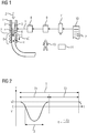
- Die oben beschriebenen Eigenschaften, Merkmale und Vorteile dieser Erfindung sowie die Art und Weise, wie diese erreicht werden, werden klarer und deutlicher verständlich im Zusammenhang mit der folgenden Beschreibung der Ausführungsbeispiele, die in Verbindung mit den Zeichnungen näher erläutert werden. Hierbei zeigen in schematischer Darstellung:
- FIG 1
- eine Stranggießanlage und
- FIG 2 und 3
- je ein Zeitdiagramm.
- Gemäß
FIG 1 weist eine Stranggießanlage eine Stranggießkokille 1 auf. In die Stranggießkokille 1 wird flüssiges Metall 2 gegossen. Das flüssige Metall 2 kann beispielsweise flüssiger Stahl oder flüssiges Aluminium sein. - Die Stranggießkokille 1 weist Seitenwände 3 auf, die mit einem Kühlmedium intensiv gekühlt werden. In der Regel bestehen die Seitenwände 3 aus Kupfer und ist das Kühlmedium Wasser. Das flüssige Metall 2 erstarrt an den Seitenwänden 3 der Stranggießkokille 1 zu einer Strangschale 4. Die Strangschale 4 umgibt einen zunächst noch flüssigen Kern 5, der erst später erstarrt.
- Die Stranggießanlage weist weiterhin eine Abzugseinrichtung 6 auf. Mittels der Abzugseinrichtung 6 wird die Strangschale 4 in einer Gießrichtung x mit einer Gießgeschwindigkeit vG aus der Stranggießkokille 1 abgezogen. In der Regel erfolgt das Abziehen der Strangschale 4, während der Kern 5 noch flüssig ist. Eine Sumpfspitze 7 des flüssigen Kerns 5 liegt also im Regelfall außerhalb der Stranggießkokille 1. Dies ist im Rahmen der vorliegenden Erfindung jedoch von untergeordneter Bedeutung. Insbesondere ist die vorliegende Erfindung auch dann anwendbar, wenn das Erstarren des flüssigen Kerns 5 noch in der Stranggießkokille 1 erfolgt, die Sumpfspitze 7 also innerhalb der Stranggießkokille 1 liegt.
- Die Stranggießanlage weist weiterhin eine Oszillationseinrichtung 8 auf. Mittels der Oszillationseinrichtung 8 wird die Stranggießkokille 1 periodisch bewegt. Die periodische Bewegung der Stranggießkokille 1 erfolgt in der Gießrichtung x. In der Regel weist die Oszillationseinrichtung 8 einen
oder mehrere Hydraulikzylinder auf, mittels derer die Bewegung der Stranggießkokille 1 bewirkt wird. Alternativ kann die Oszillationseinrichtung ein andersartiges Antriebssystem für die Stranggießkokille 1 aufweisen. - In vielen Fällen ist die Stranggießkokille 1 als gerade Kokille ausgebildet. In diesem Fall erfolgt die Oszillation der Stranggießkokille 1 parallel zur Gießrichtung x. Alternativ kann die Stranggießkokille 1 als gebogene Kokille ausgebildet sein. In diesem Fall erfolgt die Oszillation der Stranggießkokille 1 entsprechend der durch die Biegung der Kokille definierten Gießrichtung x.
- Die Oszillationseinrichtung 8 wird von einer Steuereinrichtung 9 der Stranggießanlage gesteuert. Oftmals werden von der Steuereinrichtung 9 - zusätzlich zur Ansteuerung der Oszillationseinrichtung 8 - auch andere Komponenten der Stranggießanlage 1 gesteuert, beispielsweise die Abzugseinrichtung 6 oder eine Gießeinrichtung, mittels derer das flüssige Metall 2 in die Stranggießkokille 1 gegossen wird. Die Steuereinrichtung 9 ist in der Regel als softwareprogrammierbare Steuereinrichtung ausgebildet. Ihre Wirkungsweise wird durch ein Computerprogramm 10 festgelegt, mit dem die Steuereinrichtung 9 programmiert ist. Das Computerprogramm 10 kann der Steuereinrichtung 9 beispielsweise über einen Datenträger 11 zugeführt werden, auf dem das Computerprogramm 10 in maschinenlesbarer Form - insbesondere in elektronischer Form - gespeichert ist. Der Datenträger 11 kann beispielsweise entsprechend der Darstellung in
FIG 1 als USB-Memorystick ausgebildet sein. Es sind jedoch ebenso beliebige andere Ausgestaltungen des Datenträgers 11 möglich. - Das Computerprogramm 10 umfasst Maschinencode 12, der von der Steuereinrichtung 9 unmittelbar abarbeitbar ist. Die Abarbeitung des Maschinencodes 12 durch die Steuereinrichtung 9 bewirkt, dass die Steuereinrichtung 9 zumindest die Oszillationseinrichtung 8 gemäß einem Betriebsverfahren steuert, das nachstehend näher erläutert wird.
- Aufgrund der Steuerung der Oszillationseinrichtung 8 durch die Steuereinrichtung 9 führt die Oszillationseinrichtung 8 eine periodische Bewegung aus. Die periodische Bewegung weist gemäß
FIG 2 eine Periodendauer T auf. Die Periodendauer T zerfällt in einen ersten Zeitabschnitt T1 und einen zweiten Zeitabschnitt T2. Die Zeitabschnitte T1 und T2 bilden zusammen die Periodendauer T. Es gilt also die Beziehung
- Im ersten Zeitabschnitt T1 ist die Bewegung der Stranggießkokille 1, also die durch die Oszillationseinrichtung 8 bewirkte Bewegung, eine harmonische Schwingung, der ein Geschwindigkeitsoffset v1 überlagert ist. Im ersten Zeitabschnitt T1 gilt also als Funktion der Zeit t die Beziehung

- v2 ist die Amplitude der harmonischen Schwingung. n ist eine natürliche Zahl. Meist weist n entsprechend der Darstellung in
FIG 2 den Wert 1 auf. ϕ0 ist entweder 0 oder n. - Im zweiten Zeitabschnitt T2 erfolgt die Bewegung der Stranggießkokille 1 mit konstanter Geschwindigkeit v3. Im zweiten Zeitabschnitt T2 gilt also als Funktion der Zeit t die Beziehung

- Nachfolgend wird der Fall behandelt, dass der Phasenversatz ϕ0 den Wert 0 aufweist. Der Fall, dass der Phasenversatz ϕ0 den Wert n aufweist, gestaltet sich analog bzw. kann mit einer Vorzeichenumkehr der Amplitude v2 gleichgesetzt werden.
- Der Cosinus der harmonischen Schwingung weist sowohl am Anfang als auch am Ende des ersten Zeitabschnitts T1 den Wert +1 auf. An den Grenzen des ersten Zeitabschnitts T1 ergibt sich also für die Überlagerung von harmonischer Schwingung und Geschwindigkeitsoffset v1 der Wert v1 + v2. Da der Übergang zwischen den beiden Zeitabschnitten T1 und T2 stetig sein soll, muss daher gelten

- Weiterhin gilt für die Beschleunigung a als Funktion der Zeit t im ersten Zeitabschnitt T1 die Beziehung

- Da die Beschleunigung a - siehe
FIG 3 - im zweiten Zeitabschnitt T2 den Wert 0 aufweist, muss die harmonische Schwingung als solche betrachtet eine volle Anzahl von Oszillationen ausführen. - Weiterhin muss für den zurückgelegten Weg über eine volle Periodendauer T gelten, dass er den Wert 0 aufweist. Es muss also gelten:

- Durch abschnittweises Integrieren ergibt sich daher, dass die Beziehung


- Wenn diese Bedingungen eingehalten werden, sind die Amplitude v2 der harmonischen Schwingung, der Geschwindigkeitsoffset v1 und die konstante Geschwindigkeit v3 derart aufeinander abgestimmt sind, dass der zeitliche Verlauf der Geschwindigkeit v beim Übergang vom ersten Zeitabschnitt T1 zum zweiten Zeitabschnitt T2 und beim Übergang vom zweiten Zeitabschnitt T2 einer Periode zum ersten Zeitabschnitt T1 der nachfolgenden Periode sowohl als solcher stetig ist als auch stetig differenzierbar ist.
- Im Ergebnis weist die Oszillation der Stranggießkokille 1 somit insgesamt sechs Parameter auf, nämlich die drei Zeiten T, T1 und T2 und die drei Geschwindigkeiten v1, v2 und v3. Diese sechs Parameter sind jedoch nicht unabhängig voneinander wählbar. Vielmehr sind sie durch die Gleichungen 1, 4 und 8 miteinander verknüpft.
- Wenn von den sechs Parametern eine der Zeiten T, T1 und T2 (oder eine hierzu äquivalente Größe) und eine der Geschwindigkeiten v1, v2 und v3 (oder eine hierzu äquivalente Größe) vorgegeben werden, ist lediglich eine weitere Größe erforderlich, um die verbleibenden vier Parameter eindeutig zu bestimmen. Diese weitere Größe kann beispielsweise eine der beiden verbleibenden Zeiten oder eine der beiden verbleibenden Geschwindigkeiten sein. Auch kann es sich um eine Beziehung von zwei der Zeiten zueinander oder um eine Beziehung von zwei der Geschwindigkeiten zueinander handeln. Alternativ kann es sich bei der weiteren Größe beispielsweise um eine Zeitspanne T3 (absolute Größe) oder einen Zeitanteil τ (relative Größe) handeln, während dessen die Geschwindigkeit v der Oszillation der Stranggießkokille 1 in oder entgegen der Gießrichtung x gerichtet ist. Insbesondere der Zeitanteil τ ist Fachleuten allgemein als sogenannter nonsinus-Parameter bekannt.
- Es ist daher möglich, dass der Steuereinrichtung 9 von einer Bedienperson 13 oder einem übergeordneten System 14 eine der Zeiten T, T1 und T2 (oder eine hierzu äquivalente Größe) und eine der Geschwindigkeiten v1, v2 und v3 (oder eine hierzu äquivalente Größe) und zusätzlich eine weitere Größe vorgegeben werden. In diesem Fall kann die Steuereinrichtung 9 anhand der ihr vorgegebenen Größen die Periodendauer T, den ersten Zeitabschnitt T1, den zweiten Zeitabschnitt T2, die Amplitude v2 der harmonischen Schwingung, den Geschwindigkeitsoffset v1 und die konstante Geschwindigkeit v3 ermitteln. Es ist lediglich erforderlich, dass die weitere Größe, also die dritte vorgegebene Größe, eine weitere der genannten Zeiten T, T1, T2 oder eine Beziehung von zwei der Zeiten ca. T, T1, T2 oder eine weitere der genannten Geschwindigkeiten v1, v2, v3 oder eine Beziehung von zwei der Geschwindigkeiten v1, v2, v3 zueinander ist. Alternativ kann es sich bei der weiteren Größe beispielsweise um die Zeitspanne T3 oder den Zeitanteil τ handeln. In der Praxis werden der Steuereinrichtung 9 oftmals die Frequenz (d.h. der Kehrwert der Periodendauer T), die maximale Auslenkung der Oszillation der Stranggießkokille 1 und der Zeitanteil τ vorgegeben.
- Es sind auch andere Vorgehensweisen möglich. Insbesondere ist es alternativ möglich, dass der Steuereinrichtung 9 von der Bedienperson 13 oder dem übergeordneten System 14 maximal zwei der Größen Periodendauer T, erster Zeitabschnitt T1, zweiter Zeitabschnitt T2, Amplitude v2 der harmonischen Schwingung, Geschwindigkeitsoffset v1 und konstante Geschwindigkeit v3 vorgegeben werden. Dies umfasst insbesondere nicht nur den Fall, dass der Steuereinrichtung 9 von der Bedienperson 13 oder dem übergeordneten System 14 exakt zwei der genannten Größen vorgegeben werden. Es umfasst auch die Fälle, dass der Steuereinrichtung 9 von der Bedienperson 13 oder dem übergeordneten System 14 nur eine der genannten Größen oder sogar gar keine der genannten Größen vorgegeben wird. In diesen Fällen ist es jedoch möglich, dass die Steuereinrichtung 9 die Periodendauer T, den ersten Zeitabschnitt T1, den zweiten Zeitabschnitt T2, die Amplitude v2 der harmonischen Schwingung, den Geschwindigkeitsoffset v1 und die konstante Geschwindigkeit v3 unter Verwendung der Gießgeschwindigkeit vG und/oder metallurgischer Eigenschaften des flüssigen Metalls 2 selbsttätig ermittelt. Die der Steuereinrichtung 9 von der Bedienperson 13 oder dem übergeordneten System 14 gegebenenfalls vorgegebenen Größen werden von der Steuereinrichtung 9 bei der Ermittlung berücksichtigt.
- Beispielsweise werden in der Praxis die Größen, anhand derer die Zeiten T, T1 und T2 sowie die Geschwindigkeiten v1, v2, v3 ermittelt werden, oftmals anhand der Gießgeschwindigkeit vG ermittelt. Beispielsweise können folgende Beziehungen bestehen:



- Die Koeffizienten c1 bis c6 sind in der Regel Konstanten. Alternativ kann es sich um Variable handeln. Weiterhin ist alternativ zu der obenstehend erläuterten Vorgehensweise auch eine anderweitige Ermittlung der Frequenz, der maximalen Auslenkung der Oszillation der Stranggießkokille 1 und des Zeitanteils τ möglich.
- Zusammengefasst betrifft die vorliegende Erfindung somit folgenden Sachverhalt:
Flüssiges Metall 2 wird in eine Stranggießkokille 1 der Stranggießanlage gegossen. Das flüssige Metall 2 erstarrt an Seitenwänden 3 der Stranggießkokille 1 zu einer Strangschale 4. Die Strangschale 4 wird mittels einer Abzugseinrichtung 6 der Stranggießanlage mit oder ohne noch flüssigen Kern 5 in einer Gießrichtung x mit einer Gießgeschwindigkeit vG aus der Stranggießkokille 1 abgezogen. Die Stranggießkokille 1 wird mittels einer Oszillationseinrichtung 8 der Stranggießanlage in der Gießrichtung x periodisch bewegt. Die Oszillationseinrichtung 8 wird von einer Steuereinrichtung 9 der Stranggießanlage gesteuert. Die Bewegung der Stranggießkokille 1 ist in einem ersten Zeitabschnitt T1 der Periode eine harmonische Schwingung, der ein Geschwindigkeitsoffset v1 überlagert ist. In einem zweiten Zeitabschnitt T2 der Periode erfolgt die Bewegung mit konstanter Geschwindigkeit v3. - Die vorliegende Erfindung weist viele Vorteile auf. Insbesondere kann auf einfache Weise die so genannte negative strip time, das heißt diejenige Zeit, während derer die Stranggießkokille 1 sich schneller als die Strangschale 4 nach unten bewegt, optimiert werden. Dennoch können Rucke verhindert und vermieden werden.
-
- 1
- Stranggießkokille
- 2
- flüssiges Metall
- 3
- Seitenwände der Stranggießkokille
- 4
- Strangschale
- 5
- flüssiger Kern
- 6
- Abzugseinrichtung
- 7
- Sumpfspitze
- 8
- Oszillationseinrichtung
- 9
- Steuereinrichtung
- 10
- Computerprogramm
- 11
- Datenträger
- 12
- Maschinencode
- 13
- Bedienperson
- 14
- übergeordnetes System
- a
- Beschleunigung
- t
- Zeit
- T
- Periodendauer
- T1, T2
- Zeitabschnitte
- T3
- Zeitspanne
- v
- Geschwindigkeit der Oszillation
- v1
- Geschwindigkeitsoffset
- v2
- Amplitude der harmonischen Schwingung
- v3
- konstante Geschwindigkeit
- vG
- Gießgeschwindigkeit
- x
- Gießrichtung
- τ
- Zeitanteil
Claims (13)
- Betriebsverfahren für eine Stranggießanlage,- wobei flüssiges Metall (2) in eine Stranggießkokille (1) der Stranggießanlage gegossen wird,- wobei das flüssige Metall (2) an Seitenwänden (3) der Stranggießkokille (1) zu einer Strangschale (4) erstarrt,- wobei die Strangschale (4) mittels einer Abzugseinrichtung (6) der Stranggießanlage mit oder ohne noch flüssigen Kern (5) in einer Gießrichtung (x) mit einer Gießgeschwindigkeit (vG) aus der Stranggießkokille (1) abgezogen wird,- wobei die Stranggießkokille (1) mittels einer von einer Steuereinrichtung (9) der Stranggießanlage gesteuerten Oszillationseinrichtung (8) der Stranggießanlage in der Gießrichtung (x) periodisch bewegt wird,dadurch gekennzeichnet,
dass die Bewegung der Stranggießkokille (1) in einem ersten Zeitabschnitt (T1) der Periode eine harmonische Schwingung ist, der ein Geschwindigkeitsoffset (v1) überlagert ist, und in einem zweiten Zeitabschnitt (T2) der Periode mit konstanter Geschwindigkeit (v3) erfolgt. - Betriebsverfahren nach Anspruch 1,
dadurch gekennzeichnet,
dass die harmonische Schwingung eine Amplitude (v2) aufweist und dass die Amplitude (v2) der harmonischen Schwingung, der Geschwindigkeitsoffset (v1) und die konstante Geschwindigkeit (v3) derart aufeinander abgestimmt sind, dass der zeitliche Verlauf der Geschwindigkeit (v) beim Übergang vom ersten Zeitabschnitt (T1) zum zweiten Zeitabschnitt (T2) und beim Übergang vom zweiten Zeitabschnitt (T2) einer Periode zum ersten Zeitabschnitt (T1) der nachfolgenden Periode stetig differenzierbar ist. - Betriebsverfahren nach Anspruch 2,
dadurch gekennzeichnet,- dass der Steuereinrichtung (9) von einer Bedienperson (13) oder einem übergeordneten System (14) drei Größen vorgegeben werden und- dass die Steuereinrichtung (9) anhand der ihr vorgegebenen Größen die Periodendauer (T), den ersten Zeitabschnitt (T1), den zweiten Zeitabschnitt (T2), die Amplitude (v2) der harmonischen Schwingung, den Geschwindigkeitsoffset (v1) und die konstante Geschwindigkeit (v3) ermittelt. - Betriebsverfahren nach Anspruch 3,
dadurch gekennzeichnet,- dass eine erste der drei Größen eine der Zeiten Periodendauer (T), erster Zeitabschnitt (T1) und zweiter Zeitabschnitt (T2) oder eine hierzu äquivalente Größe ist,- dass eine zweite der drei Größen eine der Geschwindigkeiten Amplitude der harmonischen Schwingung (v2), Geschwindigkeitsoffset (v1) und konstante Geschwindigkeit (v3) oder eine hierzu äquivalente Größe ist und- dass eine dritte der drei Größen eine weitere der genannten Zeiten (T, T1, T2) oder eine Beziehung von zwei der Zeiten (T, T1, T2) zueinander oder eine weitere der genannten Geschwindigkeiten (v1, v2, v3) oder eine Beziehung von zwei der Geschwindigkeiten (v1, v2, v3) zueinander oder eine Zeitspanne (T3) oder ein Zeitanteil (τ) ist, während dessen die Geschwindigkeit (v) der Oszillation der Stranggießkokille (1) in oder entgegen der Gießrichtung (x) gerichtet ist. - Betriebsverfahren nach Anspruch 1 oder 2,
dadurch gekennzeichnet,- dass der Steuereinrichtung (9) von einer Bedienperson (13) oder einem übergeordneten System (14) maximal zwei der Größen Periodendauer (T), erster Zeitabschnitt (T1), zweiter Zeitabschnitt (T2), Amplitude (v2) der harmonischen Schwingung, Geschwindigkeitsoffset (v1) und konstante Geschwindigkeit (v3) vorgegeben werden und- dass die Steuereinrichtung (9) die Periodendauer (T), den ersten Zeitabschnitt (T1), den zweiten Zeitabschnitt (T2), die Amplitude (v2) der harmonischen Schwingung, den Geschwindigkeitsoffset (v1) und die konstante Geschwindigkeit (v3) unter Verwendung der Gießgeschwindigkeit (vG) und/oder metallurgischer Eigenschaften des flüssigen Metalls (1) selbsttätig ermittelt. - Computerprogramm, das Maschinencode (12) umfasst, der von einer Steuereinrichtung (9) einer Stranggießanlage unmittelbar abarbeitbar ist, wobei die Abarbeitung des Maschinencodes (12) durch die Steuereinrichtung (9) bewirkt, dass die Steuereinrichtung (9) eine Oszillationseinrichtung (8) der Stranggießanlage derart ansteuert, dass die Stranggießkokille (1) in der Gießrichtung (x) periodisch bewegt wird und die Bewegung der Stranggießkokille (1) in einem ersten Zeitabschnitt (T1) der Periode eine harmonische Schwingung ist, der ein Geschwindigkeitsoffset (v1) überlagert ist, und in einem zweiten Zeitabschnitt (T2) der Periode mit konstanter Geschwindigkeit (v3) erfolgt.
- Computerprogramm nach Anspruch 6,
dadurch gekennzeichnet,
dass die Abarbeitung des Maschinencodes (12) durch die Steuereinrichtung (9) bewirkt, dass die harmonische Schwingung eine Amplitude (v2) aufweist und dass die Amplitude (v2) der harmonischen Schwingung, der Geschwindigkeitsoffset (v1) und die konstante Geschwindigkeit (v3) derart aufeinander abgestimmt sind, dass der zeitliche Verlauf der Geschwindigkeit (v) beim Übergang vom ersten Zeitabschnitt (T1) zum zweiten Zeitabschnitt (T2) und beim Übergang vom zweiten Zeitabschnitt (T2) einer Periode zum ersten Zeitabschnitt (T1) der nachfolgenden Periode stetig differenzierbar ist. - Computerprogramm nach Anspruch 7,
dadurch gekennzeichnet,
dass die Abarbeitung des Maschinencodes (12) durch die Steuereinrichtung (9) bewirkt,- dass die Steuereinrichtung (9) von einer Bedienperson (13) oder einem übergeordneten System (14) drei Größen entgegennimmt und- dass die Steuereinrichtung (9) anhand der ihr vorgegebenen Größen die Periodendauer (T), den ersten Zeitabschnitt (T1), den zweiten Zeitabschnitt (T2), die Amplitude (v2) der harmonischen Schwingung, den Geschwindigkeitsoffset (v1) und die konstante Geschwindigkeit (v3) ermittelt. - Computerprogramm nach Anspruch 8,
dadurch gekennzeichnet,- dass eine erste der drei Größen eine der Zeiten Periodendauer (T), erster Zeitabschnitt (T1) und zweiter Zeitabschnitt (T2) oder eine hierzu äquivalente Größe ist,- dass eine zweite der drei Größen eine der Geschwindigkeiten Amplitude der harmonischen Schwingung (v2), Geschwindigkeitsoffset (v1) und konstante Geschwindigkeit (v3) oder eine hierzu äquivalente Größe ist und- dass eine dritte der drei Größen eine weitere der genannten Zeiten (T, T1, T2) oder eine Beziehung von zwei der Zeiten (T, T1, T2) zueinander oder eine weitere der genannten Geschwindigkeiten (v1, v2, v3) oder eine Beziehung von zwei der Geschwindigkeiten (v1, v2, v3) zueinander oder eine Zeitspanne (T3) oder ein Zeitanteil (τ) ist, während dessen die Geschwindigkeit (v) der Oszillation der Stranggießkokille (1) in oder entgegen der Gießrichtung (x) gerichtet ist. - Computerprogramm nach Anspruch 6 oder 7,
dadurch gekennzeichnet,
dass die Abarbeitung des Maschinencodes (12) durch die Steuereinrichtung (9) bewirkt,- dass die Steuereinrichtung (9) von einer Bedienperson (13) oder einem übergeordneten System (14) maximal zwei der Größen Periodendauer (T), erster Zeitabschnitt (T1), zweiter Zeitabschnitt (T2), Amplitude (v2) der harmonischen Schwingung, Geschwindigkeitsoffset (v1) und konstante Geschwindigkeit (v3) entgegennimmt und- dass die Steuereinrichtung (9) die Periodendauer (T), den ersten Zeitabschnitt (T1), den zweiten Zeitabschnitt (T2), die Amplitude (v2) der harmonischen Schwingung, den Geschwindigkeitsoffset (v1) und die konstante Geschwindigkeit (v3) unter Verwendung der Gießgeschwindigkeit (vG) und/oder metallurgischer Eigenschaften des flüssigen Metalls (2) selbsttätig ermittelt. - Computerprogramm nach einem der Ansprüche 6 bis 10,
dadurch gekennzeichnet,
dass es auf einem Datenträger (11) in maschinenlesbarer Form gespeichert ist. - Steuereinrichtung für eine Stranggießanlage,
dadurch gekennzeichnet,
dass die Steuereinrichtung mit einem Computerprogramm (10) nach einem der Ansprüche 6 bis 10 programmiert ist. - Stranggießanlage,- wobei die Stranggießanlage eine Stranggießkokille (1) aufweist, in die flüssiges Metall (2) gegossen wird,- wobei das flüssige Metall (2) an Seitenwänden (3) der Stranggießkokille (1) zu einer Strangschale (4) erstarrt,- wobei die Stranggießanlage eine Abzugseinrichtung (6) aufweist, mittels derer die Strangschale (4) mit oder ohne noch flüssigen Kern (5) in einer Gießrichtung (x) mit einer Gießgeschwindigkeit (vG) aus der Stranggießkokille (1) abgezogen wird,- wobei die Stranggießanlage eine Oszillationseinrichtung (8) aufweist, mittels derer die Stranggießkokille (1) in der Gießrichtung (x) periodisch bewegt wird,- wobei die Stranggießanlage eine Steuereinrichtung (9) aufweist, von der die Oszillationseinrichtung (8) gesteuert wird,dadurch gekennzeichnet,
dass die Steuereinrichtung (9) als Steuereinrichtung nach Anspruch 12 ausgebildet ist.
Applications Claiming Priority (2)
| Application Number | Priority Date | Filing Date | Title |
|---|---|---|---|
| ATA50273/2015A AT517006B1 (de) | 2015-04-07 | 2015-04-07 | Stranggießen mit optimierter Oszillation der Stranggießkokille |
| PCT/EP2016/054057 WO2016162141A1 (de) | 2015-04-07 | 2016-02-26 | Stranggiessen mit optimierter oszillation der stranggiesskokille |
Publications (2)
| Publication Number | Publication Date |
|---|---|
| EP3280557A1 EP3280557A1 (de) | 2018-02-14 |
| EP3280557B1 true EP3280557B1 (de) | 2019-10-02 |
Family
ID=55436106
Family Applications (1)
| Application Number | Title | Priority Date | Filing Date |
|---|---|---|---|
| EP16706366.8A Active EP3280557B1 (de) | 2015-04-07 | 2016-02-26 | Stranggiessen mit optimierter oszillation der stranggiesskokille |
Country Status (4)
| Country | Link |
|---|---|
| EP (1) | EP3280557B1 (de) |
| CN (1) | CN107427908B (de) |
| AT (1) | AT517006B1 (de) |
| WO (1) | WO2016162141A1 (de) |
Families Citing this family (4)
| Publication number | Priority date | Publication date | Assignee | Title |
|---|---|---|---|---|
| DE102018215566A1 (de) | 2018-09-13 | 2020-03-19 | Sms Group Gmbh | Verfahren und Computerprogrammprodukt zum Betreiben einer Oszillationsvorrichtung sowie die entsprechende Oszillationsvorrichtung |
| CN109773146B (zh) * | 2019-01-11 | 2021-03-16 | 中冶赛迪技术研究中心有限公司 | 一种直驱式电液伺服结晶器振动曲线优化控制方法 |
| CN113084112B (zh) * | 2021-04-02 | 2022-08-02 | 河北农业大学 | 连铸结晶器非正弦振动方法 |
| CN114367644B (zh) * | 2021-12-15 | 2023-09-01 | 唐山渤海冶金智能装备有限公司 | 一种连铸结晶器振动轨迹曲线切换方法 |
Family Cites Families (10)
| Publication number | Priority date | Publication date | Assignee | Title |
|---|---|---|---|---|
| CH498675A (de) * | 1968-10-11 | 1970-11-15 | Concast Ag | Verfahren zum Stranggiessen von Knüppeln aus Stahl |
| DE58901200D1 (de) * | 1988-01-28 | 1992-05-27 | Clecim Sa | Verfahren und vorrichtung zum oszillieren einer stahlstranggiesskokille. |
| FR2689045B1 (fr) * | 1992-03-31 | 1994-06-24 | Clecim Sa | Procede de coulee continue. |
| FR2704788B1 (fr) * | 1993-05-04 | 1995-07-28 | Clecim Sa | Dispositif de commande des mouvements d'une lingotiere. |
| JPH10128511A (ja) * | 1996-10-31 | 1998-05-19 | Sumitomo Metal Ind Ltd | 鋼の連続鋳造方法 |
| DE102006001196A1 (de) * | 2006-01-10 | 2007-07-12 | Sms Demag Ag | Verfahren zum Regeln der Oszillationsbewegung einer Stranggießkokille beim Gießen von flüssigem Metall, insbesondere von flüssigem Stahlwerkstoff |
| CN101537477B (zh) * | 2009-04-16 | 2010-12-08 | 中冶赛迪工程技术股份有限公司 | 一种用于结晶器振动非正弦波形发生器 |
| CN103331435A (zh) * | 2013-07-03 | 2013-10-02 | 上海大学 | 外加旋转磁场和电流复合控制金属凝固相组织的方法及其熔铸装置 |
| CN103600043B (zh) * | 2013-11-27 | 2015-06-17 | 东北大学 | 连铸结晶器振动模拟试验装置及其非正弦振动控制方法 |
| CN103752783A (zh) * | 2013-12-27 | 2014-04-30 | 燕山大学 | 一种连铸结晶器非正弦振动方法 |
-
2015
- 2015-04-07 AT ATA50273/2015A patent/AT517006B1/de active
-
2016
- 2016-02-26 EP EP16706366.8A patent/EP3280557B1/de active Active
- 2016-02-26 CN CN201680019988.3A patent/CN107427908B/zh active Active
- 2016-02-26 WO PCT/EP2016/054057 patent/WO2016162141A1/de not_active Ceased
Non-Patent Citations (1)
| Title |
|---|
| None * |
Also Published As
| Publication number | Publication date |
|---|---|
| CN107427908A (zh) | 2017-12-01 |
| CN107427908B (zh) | 2019-09-20 |
| AT517006B1 (de) | 2018-08-15 |
| EP3280557A1 (de) | 2018-02-14 |
| WO2016162141A1 (de) | 2016-10-13 |
| AT517006A1 (de) | 2016-10-15 |
Similar Documents
| Publication | Publication Date | Title |
|---|---|---|
| AT517006B1 (de) | Stranggießen mit optimierter Oszillation der Stranggießkokille | |
| DE19639297C2 (de) | Verfahren und Vorrichtung für Hochgeschwindigkeits-Stranggießanlagen mit einer Strangdickenreduktion während der Erstarrung | |
| DE2923113A1 (de) | Verfahren zum aendern eines strangquerschnittformates und kokille zur durchfuehrung des verfahrens | |
| DE2814600C2 (de) | Verfahren und Vorrichtung zum Stahlstranggießen | |
| DE102009001511A1 (de) | Verfahren und Vorrichtung zur Einparkhilfe | |
| DE102020209794A1 (de) | Verfahren zur Steuerung oder Regelung der Temperatur eines Gießstrangs in einer Stranggießanlage | |
| DE102006015359B4 (de) | Betriebsverfahren für eine Anlage mit einem mechanisch bewegbaren Element sowie Datenträger und Steuereinrichtung zur Realisierung eines derartigen Betriebsverfahrens | |
| EP2523764B1 (de) | Regelverfahren für den giessspiegel einer stranggiesskokille | |
| DE102004001037A1 (de) | Diversifizierte Regelung der Sekundärkühlung einer Stranggießanlage | |
| DD284175A5 (de) | Verfahren zum kuehlen eines metallischen gegenstandes waehrend des stranggiessens | |
| EP3623077B1 (de) | Verfahren und computerprogrammprodukt zum betreiben einer oszillationsvorrichtung sowie die entsprechende oszillationsvorrichtung | |
| DE2542290C2 (de) | Verfahren zum Steuern des Stranggießens von Metallen | |
| EP0115312B1 (de) | Verfahren zum Schleudergiessen | |
| EP4101560B1 (de) | Rühren bei gegossenen knüppeln oder vorblöcken mit oszillierendem strangrührer und steuerprogramm | |
| EP0116030A2 (de) | Verfahren zum Überwachen einer Bogenstranggiessanlage | |
| DE69000282T2 (de) | Verfahren und vorrichtung zur herstellung von duennen metallprodukten mittels strangguss. | |
| DE2326407A1 (de) | Verfahren zur steuerung der walzgeschwindigkeit bei einer kontinuierlichen walzanlage | |
| DE69303309T3 (de) | Verfahren zum Stranggiessen | |
| EP2251459B1 (de) | Verfahren und Vorrichtung zur Bereitstellung flüssigen Siliziums | |
| WO2001087518A1 (de) | VERFAHREN UND ANLAGE ZUM STRANGGIEssEN VON BRAMMEN, INSBESONDERE VON DÜNNBRAMMEN MIT VERGLEICHSWEISE HOHEN GIEssGESCHWINDIGKEITEN | |
| AT528176A1 (de) | Giesswalzverbundanlage mit verbesserter produktivität | |
| EP3323529B1 (de) | Stranggiessanlage mit flexibler konfiguration der richtstrecke | |
| EP1133370A1 (de) | Verfahren zum oszillieren einer stranggiesskokille mittels variabler oszillationsparameter | |
| LU82416A1 (de) | Vorrichtung und verfahren zum chargenweisen giessen in einer stahlstranggiesserei | |
| EP0148323A1 (de) | Stranggiessverfahren und Vorrichtung zum Herstellen von Mehrschichtwerkstoffen |
Legal Events
| Date | Code | Title | Description |
|---|---|---|---|
| STAA | Information on the status of an ep patent application or granted ep patent |
Free format text: STATUS: THE INTERNATIONAL PUBLICATION HAS BEEN MADE |
|
| PUAI | Public reference made under article 153(3) epc to a published international application that has entered the european phase |
Free format text: ORIGINAL CODE: 0009012 |
|
| STAA | Information on the status of an ep patent application or granted ep patent |
Free format text: STATUS: REQUEST FOR EXAMINATION WAS MADE |
|
| 17P | Request for examination filed |
Effective date: 20171107 |
|
| AK | Designated contracting states |
Kind code of ref document: A1 Designated state(s): AL AT BE BG CH CY CZ DE DK EE ES FI FR GB GR HR HU IE IS IT LI LT LU LV MC MK MT NL NO PL PT RO RS SE SI SK SM TR |
|
| AX | Request for extension of the european patent |
Extension state: BA ME |
|
| DAV | Request for validation of the european patent (deleted) | ||
| DAX | Request for extension of the european patent (deleted) | ||
| GRAP | Despatch of communication of intention to grant a patent |
Free format text: ORIGINAL CODE: EPIDOSNIGR1 |
|
| STAA | Information on the status of an ep patent application or granted ep patent |
Free format text: STATUS: GRANT OF PATENT IS INTENDED |
|
| INTG | Intention to grant announced |
Effective date: 20190516 |
|
| GRAS | Grant fee paid |
Free format text: ORIGINAL CODE: EPIDOSNIGR3 |
|
| GRAA | (expected) grant |
Free format text: ORIGINAL CODE: 0009210 |
|
| STAA | Information on the status of an ep patent application or granted ep patent |
Free format text: STATUS: THE PATENT HAS BEEN GRANTED |
|
| AK | Designated contracting states |
Kind code of ref document: B1 Designated state(s): AL AT BE BG CH CY CZ DE DK EE ES FI FR GB GR HR HU IE IS IT LI LT LU LV MC MK MT NL NO PL PT RO RS SE SI SK SM TR |
|
| REG | Reference to a national code |
Ref country code: GB Ref legal event code: FG4D Free format text: NOT ENGLISH |
|
| REG | Reference to a national code |
Ref country code: CH Ref legal event code: EP Ref country code: AT Ref legal event code: REF Ref document number: 1185640 Country of ref document: AT Kind code of ref document: T Effective date: 20191015 |
|
| REG | Reference to a national code |
Ref country code: DE Ref legal event code: R096 Ref document number: 502016006883 Country of ref document: DE |
|
| REG | Reference to a national code |
Ref country code: IE Ref legal event code: FG4D Free format text: LANGUAGE OF EP DOCUMENT: GERMAN |
|
| REG | Reference to a national code |
Ref country code: NL Ref legal event code: MP Effective date: 20191002 |
|
| REG | Reference to a national code |
Ref country code: LT Ref legal event code: MG4D |
|
| PG25 | Lapsed in a contracting state [announced via postgrant information from national office to epo] |
Ref country code: PL Free format text: LAPSE BECAUSE OF FAILURE TO SUBMIT A TRANSLATION OF THE DESCRIPTION OR TO PAY THE FEE WITHIN THE PRESCRIBED TIME-LIMIT Effective date: 20191002 Ref country code: NL Free format text: LAPSE BECAUSE OF FAILURE TO SUBMIT A TRANSLATION OF THE DESCRIPTION OR TO PAY THE FEE WITHIN THE PRESCRIBED TIME-LIMIT Effective date: 20191002 Ref country code: LT Free format text: LAPSE BECAUSE OF FAILURE TO SUBMIT A TRANSLATION OF THE DESCRIPTION OR TO PAY THE FEE WITHIN THE PRESCRIBED TIME-LIMIT Effective date: 20191002 Ref country code: ES Free format text: LAPSE BECAUSE OF FAILURE TO SUBMIT A TRANSLATION OF THE DESCRIPTION OR TO PAY THE FEE WITHIN THE PRESCRIBED TIME-LIMIT Effective date: 20191002 Ref country code: FI Free format text: LAPSE BECAUSE OF FAILURE TO SUBMIT A TRANSLATION OF THE DESCRIPTION OR TO PAY THE FEE WITHIN THE PRESCRIBED TIME-LIMIT Effective date: 20191002 Ref country code: BG Free format text: LAPSE BECAUSE OF FAILURE TO SUBMIT A TRANSLATION OF THE DESCRIPTION OR TO PAY THE FEE WITHIN THE PRESCRIBED TIME-LIMIT Effective date: 20200102 Ref country code: GR Free format text: LAPSE BECAUSE OF FAILURE TO SUBMIT A TRANSLATION OF THE DESCRIPTION OR TO PAY THE FEE WITHIN THE PRESCRIBED TIME-LIMIT Effective date: 20200103 Ref country code: NO Free format text: LAPSE BECAUSE OF FAILURE TO SUBMIT A TRANSLATION OF THE DESCRIPTION OR TO PAY THE FEE WITHIN THE PRESCRIBED TIME-LIMIT Effective date: 20200102 Ref country code: SE Free format text: LAPSE BECAUSE OF FAILURE TO SUBMIT A TRANSLATION OF THE DESCRIPTION OR TO PAY THE FEE WITHIN THE PRESCRIBED TIME-LIMIT Effective date: 20191002 Ref country code: LV Free format text: LAPSE BECAUSE OF FAILURE TO SUBMIT A TRANSLATION OF THE DESCRIPTION OR TO PAY THE FEE WITHIN THE PRESCRIBED TIME-LIMIT Effective date: 20191002 Ref country code: PT Free format text: LAPSE BECAUSE OF FAILURE TO SUBMIT A TRANSLATION OF THE DESCRIPTION OR TO PAY THE FEE WITHIN THE PRESCRIBED TIME-LIMIT Effective date: 20200203 |
|
| PG25 | Lapsed in a contracting state [announced via postgrant information from national office to epo] |
Ref country code: HR Free format text: LAPSE BECAUSE OF FAILURE TO SUBMIT A TRANSLATION OF THE DESCRIPTION OR TO PAY THE FEE WITHIN THE PRESCRIBED TIME-LIMIT Effective date: 20191002 Ref country code: IS Free format text: LAPSE BECAUSE OF FAILURE TO SUBMIT A TRANSLATION OF THE DESCRIPTION OR TO PAY THE FEE WITHIN THE PRESCRIBED TIME-LIMIT Effective date: 20200224 Ref country code: CZ Free format text: LAPSE BECAUSE OF FAILURE TO SUBMIT A TRANSLATION OF THE DESCRIPTION OR TO PAY THE FEE WITHIN THE PRESCRIBED TIME-LIMIT Effective date: 20191002 Ref country code: RS Free format text: LAPSE BECAUSE OF FAILURE TO SUBMIT A TRANSLATION OF THE DESCRIPTION OR TO PAY THE FEE WITHIN THE PRESCRIBED TIME-LIMIT Effective date: 20191002 |
|
| PG25 | Lapsed in a contracting state [announced via postgrant information from national office to epo] |
Ref country code: AL Free format text: LAPSE BECAUSE OF FAILURE TO SUBMIT A TRANSLATION OF THE DESCRIPTION OR TO PAY THE FEE WITHIN THE PRESCRIBED TIME-LIMIT Effective date: 20191002 |
|
| REG | Reference to a national code |
Ref country code: DE Ref legal event code: R097 Ref document number: 502016006883 Country of ref document: DE |
|
| PG2D | Information on lapse in contracting state deleted |
Ref country code: IS |
|
| PG25 | Lapsed in a contracting state [announced via postgrant information from national office to epo] |
Ref country code: RO Free format text: LAPSE BECAUSE OF FAILURE TO SUBMIT A TRANSLATION OF THE DESCRIPTION OR TO PAY THE FEE WITHIN THE PRESCRIBED TIME-LIMIT Effective date: 20191002 Ref country code: DK Free format text: LAPSE BECAUSE OF FAILURE TO SUBMIT A TRANSLATION OF THE DESCRIPTION OR TO PAY THE FEE WITHIN THE PRESCRIBED TIME-LIMIT Effective date: 20191002 Ref country code: EE Free format text: LAPSE BECAUSE OF FAILURE TO SUBMIT A TRANSLATION OF THE DESCRIPTION OR TO PAY THE FEE WITHIN THE PRESCRIBED TIME-LIMIT Effective date: 20191002 Ref country code: IS Free format text: LAPSE BECAUSE OF FAILURE TO SUBMIT A TRANSLATION OF THE DESCRIPTION OR TO PAY THE FEE WITHIN THE PRESCRIBED TIME-LIMIT Effective date: 20200202 |
|
| PLBE | No opposition filed within time limit |
Free format text: ORIGINAL CODE: 0009261 |
|
| STAA | Information on the status of an ep patent application or granted ep patent |
Free format text: STATUS: NO OPPOSITION FILED WITHIN TIME LIMIT |
|
| PG25 | Lapsed in a contracting state [announced via postgrant information from national office to epo] |
Ref country code: SK Free format text: LAPSE BECAUSE OF FAILURE TO SUBMIT A TRANSLATION OF THE DESCRIPTION OR TO PAY THE FEE WITHIN THE PRESCRIBED TIME-LIMIT Effective date: 20191002 Ref country code: SM Free format text: LAPSE BECAUSE OF FAILURE TO SUBMIT A TRANSLATION OF THE DESCRIPTION OR TO PAY THE FEE WITHIN THE PRESCRIBED TIME-LIMIT Effective date: 20191002 Ref country code: IT Free format text: LAPSE BECAUSE OF FAILURE TO SUBMIT A TRANSLATION OF THE DESCRIPTION OR TO PAY THE FEE WITHIN THE PRESCRIBED TIME-LIMIT Effective date: 20191002 |
|
| 26N | No opposition filed |
Effective date: 20200703 |
|
| REG | Reference to a national code |
Ref country code: CH Ref legal event code: PL |
|
| GBPC | Gb: european patent ceased through non-payment of renewal fee |
Effective date: 20200226 |
|
| REG | Reference to a national code |
Ref country code: BE Ref legal event code: MM Effective date: 20200229 |
|
| PG25 | Lapsed in a contracting state [announced via postgrant information from national office to epo] |
Ref country code: MC Free format text: LAPSE BECAUSE OF FAILURE TO SUBMIT A TRANSLATION OF THE DESCRIPTION OR TO PAY THE FEE WITHIN THE PRESCRIBED TIME-LIMIT Effective date: 20191002 Ref country code: LU Free format text: LAPSE BECAUSE OF NON-PAYMENT OF DUE FEES Effective date: 20200226 |
|
| PG25 | Lapsed in a contracting state [announced via postgrant information from national office to epo] |
Ref country code: LI Free format text: LAPSE BECAUSE OF NON-PAYMENT OF DUE FEES Effective date: 20200229 Ref country code: CH Free format text: LAPSE BECAUSE OF NON-PAYMENT OF DUE FEES Effective date: 20200229 Ref country code: SI Free format text: LAPSE BECAUSE OF FAILURE TO SUBMIT A TRANSLATION OF THE DESCRIPTION OR TO PAY THE FEE WITHIN THE PRESCRIBED TIME-LIMIT Effective date: 20191002 |
|
| PG25 | Lapsed in a contracting state [announced via postgrant information from national office to epo] |
Ref country code: GB Free format text: LAPSE BECAUSE OF NON-PAYMENT OF DUE FEES Effective date: 20200226 Ref country code: IE Free format text: LAPSE BECAUSE OF NON-PAYMENT OF DUE FEES Effective date: 20200226 Ref country code: FR Free format text: LAPSE BECAUSE OF NON-PAYMENT OF DUE FEES Effective date: 20200229 |
|
| PG25 | Lapsed in a contracting state [announced via postgrant information from national office to epo] |
Ref country code: BE Free format text: LAPSE BECAUSE OF NON-PAYMENT OF DUE FEES Effective date: 20200229 |
|
| REG | Reference to a national code |
Ref country code: AT Ref legal event code: MM01 Ref document number: 1185640 Country of ref document: AT Kind code of ref document: T Effective date: 20210226 |
|
| PG25 | Lapsed in a contracting state [announced via postgrant information from national office to epo] |
Ref country code: AT Free format text: LAPSE BECAUSE OF NON-PAYMENT OF DUE FEES Effective date: 20210226 |
|
| PG25 | Lapsed in a contracting state [announced via postgrant information from national office to epo] |
Ref country code: TR Free format text: LAPSE BECAUSE OF FAILURE TO SUBMIT A TRANSLATION OF THE DESCRIPTION OR TO PAY THE FEE WITHIN THE PRESCRIBED TIME-LIMIT Effective date: 20191002 Ref country code: MT Free format text: LAPSE BECAUSE OF FAILURE TO SUBMIT A TRANSLATION OF THE DESCRIPTION OR TO PAY THE FEE WITHIN THE PRESCRIBED TIME-LIMIT Effective date: 20191002 Ref country code: CY Free format text: LAPSE BECAUSE OF FAILURE TO SUBMIT A TRANSLATION OF THE DESCRIPTION OR TO PAY THE FEE WITHIN THE PRESCRIBED TIME-LIMIT Effective date: 20191002 |
|
| PG25 | Lapsed in a contracting state [announced via postgrant information from national office to epo] |
Ref country code: MK Free format text: LAPSE BECAUSE OF FAILURE TO SUBMIT A TRANSLATION OF THE DESCRIPTION OR TO PAY THE FEE WITHIN THE PRESCRIBED TIME-LIMIT Effective date: 20191002 |
|
| REG | Reference to a national code |
Ref country code: DE Ref legal event code: R082 Ref document number: 502016006883 Country of ref document: DE Representative=s name: LINDNER BLAUMEIER, PATENT- UND RECHTSANWAELTE,, DE |
|
| PGFP | Annual fee paid to national office [announced via postgrant information from national office to epo] |
Ref country code: DE Payment date: 20260218 Year of fee payment: 11 |