EP3280610B1 - Vorrichtung für einen fahrzeugsitz und fahrzeugsitz - Google Patents
Vorrichtung für einen fahrzeugsitz und fahrzeugsitz Download PDFInfo
- Publication number
- EP3280610B1 EP3280610B1 EP16712937.8A EP16712937A EP3280610B1 EP 3280610 B1 EP3280610 B1 EP 3280610B1 EP 16712937 A EP16712937 A EP 16712937A EP 3280610 B1 EP3280610 B1 EP 3280610B1
- Authority
- EP
- European Patent Office
- Prior art keywords
- seat
- vehicle seat
- backrest
- longitudinal
- memory
- Prior art date
- Legal status (The legal status is an assumption and is not a legal conclusion. Google has not performed a legal analysis and makes no representation as to the accuracy of the status listed.)
- Active
Links
Images




Classifications
-
- B—PERFORMING OPERATIONS; TRANSPORTING
- B60—VEHICLES IN GENERAL
- B60N—SEATS SPECIALLY ADAPTED FOR VEHICLES; VEHICLE PASSENGER ACCOMMODATION NOT OTHERWISE PROVIDED FOR
- B60N2/00—Seats specially adapted for vehicles; Arrangement or mounting of seats in vehicles
- B60N2/02—Seats specially adapted for vehicles; Arrangement or mounting of seats in vehicles the seat or part thereof being movable, e.g. adjustable
-
- B—PERFORMING OPERATIONS; TRANSPORTING
- B60—VEHICLES IN GENERAL
- B60N—SEATS SPECIALLY ADAPTED FOR VEHICLES; VEHICLE PASSENGER ACCOMMODATION NOT OTHERWISE PROVIDED FOR
- B60N2/00—Seats specially adapted for vehicles; Arrangement or mounting of seats in vehicles
- B60N2/02—Seats specially adapted for vehicles; Arrangement or mounting of seats in vehicles the seat or part thereof being movable, e.g. adjustable
- B60N2/04—Seats specially adapted for vehicles; Arrangement or mounting of seats in vehicles the seat or part thereof being movable, e.g. adjustable the whole seat being movable
- B60N2/06—Seats specially adapted for vehicles; Arrangement or mounting of seats in vehicles the seat or part thereof being movable, e.g. adjustable the whole seat being movable slidable
-
- B—PERFORMING OPERATIONS; TRANSPORTING
- B60—VEHICLES IN GENERAL
- B60N—SEATS SPECIALLY ADAPTED FOR VEHICLES; VEHICLE PASSENGER ACCOMMODATION NOT OTHERWISE PROVIDED FOR
- B60N2/00—Seats specially adapted for vehicles; Arrangement or mounting of seats in vehicles
- B60N2/02—Seats specially adapted for vehicles; Arrangement or mounting of seats in vehicles the seat or part thereof being movable, e.g. adjustable
- B60N2/04—Seats specially adapted for vehicles; Arrangement or mounting of seats in vehicles the seat or part thereof being movable, e.g. adjustable the whole seat being movable
- B60N2/06—Seats specially adapted for vehicles; Arrangement or mounting of seats in vehicles the seat or part thereof being movable, e.g. adjustable the whole seat being movable slidable
- B60N2/07—Slide construction
- B60N2/0702—Slide construction characterised by its cross-section
- B60N2/0705—Slide construction characterised by its cross-section omega-shaped
-
- B—PERFORMING OPERATIONS; TRANSPORTING
- B60—VEHICLES IN GENERAL
- B60N—SEATS SPECIALLY ADAPTED FOR VEHICLES; VEHICLE PASSENGER ACCOMMODATION NOT OTHERWISE PROVIDED FOR
- B60N2/00—Seats specially adapted for vehicles; Arrangement or mounting of seats in vehicles
- B60N2/02—Seats specially adapted for vehicles; Arrangement or mounting of seats in vehicles the seat or part thereof being movable, e.g. adjustable
- B60N2/04—Seats specially adapted for vehicles; Arrangement or mounting of seats in vehicles the seat or part thereof being movable, e.g. adjustable the whole seat being movable
- B60N2/06—Seats specially adapted for vehicles; Arrangement or mounting of seats in vehicles the seat or part thereof being movable, e.g. adjustable the whole seat being movable slidable
- B60N2/08—Seats specially adapted for vehicles; Arrangement or mounting of seats in vehicles the seat or part thereof being movable, e.g. adjustable the whole seat being movable slidable characterised by the locking device
- B60N2/0812—Location of the latch
- B60N2/0818—Location of the latch inside the rail
-
- B—PERFORMING OPERATIONS; TRANSPORTING
- B60—VEHICLES IN GENERAL
- B60N—SEATS SPECIALLY ADAPTED FOR VEHICLES; VEHICLE PASSENGER ACCOMMODATION NOT OTHERWISE PROVIDED FOR
- B60N2/00—Seats specially adapted for vehicles; Arrangement or mounting of seats in vehicles
- B60N2/02—Seats specially adapted for vehicles; Arrangement or mounting of seats in vehicles the seat or part thereof being movable, e.g. adjustable
- B60N2/04—Seats specially adapted for vehicles; Arrangement or mounting of seats in vehicles the seat or part thereof being movable, e.g. adjustable the whole seat being movable
- B60N2/06—Seats specially adapted for vehicles; Arrangement or mounting of seats in vehicles the seat or part thereof being movable, e.g. adjustable the whole seat being movable slidable
- B60N2/08—Seats specially adapted for vehicles; Arrangement or mounting of seats in vehicles the seat or part thereof being movable, e.g. adjustable the whole seat being movable slidable characterised by the locking device
- B60N2/0831—Movement of the latch
- B60N2/0862—Movement of the latch sliding
- B60N2/0875—Movement of the latch sliding in a vertical direction
-
- B—PERFORMING OPERATIONS; TRANSPORTING
- B60—VEHICLES IN GENERAL
- B60N—SEATS SPECIALLY ADAPTED FOR VEHICLES; VEHICLE PASSENGER ACCOMMODATION NOT OTHERWISE PROVIDED FOR
- B60N2/00—Seats specially adapted for vehicles; Arrangement or mounting of seats in vehicles
- B60N2/02—Seats specially adapted for vehicles; Arrangement or mounting of seats in vehicles the seat or part thereof being movable, e.g. adjustable
- B60N2/04—Seats specially adapted for vehicles; Arrangement or mounting of seats in vehicles the seat or part thereof being movable, e.g. adjustable the whole seat being movable
- B60N2/12—Seats specially adapted for vehicles; Arrangement or mounting of seats in vehicles the seat or part thereof being movable, e.g. adjustable the whole seat being movable slidable and tiltable
- B60N2/123—Seats specially adapted for vehicles; Arrangement or mounting of seats in vehicles the seat or part thereof being movable, e.g. adjustable the whole seat being movable slidable and tiltable and provided with memory locks
-
- B—PERFORMING OPERATIONS; TRANSPORTING
- B60—VEHICLES IN GENERAL
- B60N—SEATS SPECIALLY ADAPTED FOR VEHICLES; VEHICLE PASSENGER ACCOMMODATION NOT OTHERWISE PROVIDED FOR
- B60N2/00—Seats specially adapted for vehicles; Arrangement or mounting of seats in vehicles
- B60N2/02—Seats specially adapted for vehicles; Arrangement or mounting of seats in vehicles the seat or part thereof being movable, e.g. adjustable
- B60N2/20—Seats specially adapted for vehicles; Arrangement or mounting of seats in vehicles the seat or part thereof being movable, e.g. adjustable the back-rest being tiltable, e.g. to permit easy access
Definitions
- the invention relates to a device for a vehicle seat with the features of the preamble of claim 1, as well as a vehicle seat.
- the easy-entry system can be actuated by an unlocking lever, which is usually arranged on a backrest of the vehicle seat, as a result of which the backrest of the vehicle seat swivels out of an entry area. If the vehicle seat is arranged on rails, the vehicle seat can additionally or alternatively be displaceable out of the entry area in the direction of travel when the unlocking lever is actuated.
- an easy-entry adjustment device for a vehicle seat enables the vehicle seat to be adjusted between a use position and an easy-entry position. Such adjustability is particularly advantageous for vehicles that have only one door per side of the vehicle.
- both a backrest fitting of the adjustment device and a longitudinal seat lock of the adjustment device are released. Releasing the backrest fitting enables the seat back of the vehicle seat to be pivoted forward in the direction of a seat part of the vehicle seat, while releasing the longitudinal seat lock enables the entire vehicle seat to be advanced in the direction of travel. A vehicle occupant thus gains access to the rear seats of the vehicle.
- the longitudinal adjuster comprises two pairs of rails, each with two seat rails that can be displaced relative to one another, namely an upper rail and a lower rail, which mutually engage around one another.
- the upper rail can be displaced relative to the lower rail within a comfort adjustment range and also into an easy-entry position.
- a longitudinal adjuster for a vehicle seat is known, with a freely pivoting backrest, with a first seat rail, a second seat rail relative to which the first seat rail is displaceable in the longitudinal direction, a locking device for locking the longitudinal adjuster, one of the first seat rails assigned and with the second seat rail cooperating memory device, which stores a set longitudinal seat position, which is left by a longitudinal displacement of the vehicle seat made when the backrest is pivoted free and is taken back when it is pushed back, and a control device assigned to the first seat rail, which controls the memory device for resetting and the locking device for unlocking, the Control device is arranged to be movable relative to the first seat rail in the longitudinal direction to a limited extent.
- a guide track arrangement comprising a memory arrangement which can be put into an engagement state in order to set a position selected by a user.
- the memory assembly When the memory assembly is in an engaged condition and in the position selected by a user, the memory assembly resists movement of a first rail relative to a second rail in a rearward direction.
- the memory assembly When the memory assembly is in the engaged condition and in the position selected by a user and the second rail is moving in a forward direction relative to the first rail, the memory assembly is moving in the rearward direction relative to the second rail moved to a first position.
- the invention is based on the object of improving a device for a vehicle seat of the type mentioned at the outset, in particular to enable a modular, if required, provision of an easy-entry comfort function and an easy-entry hold-open function and to provide a corresponding vehicle seat.
- a device for a vehicle seat which has a seat part and a backrest and the seat part of which is connected to a first seat rail of a longitudinal adjuster.
- the first seat rail of the longitudinal adjuster is guided displaceably in the longitudinal direction in a structurally fixed second seat rail of the longitudinal adjuster.
- the vehicle seat can be moved from the position of use into an easy-entry position for simplified access to the rear seats when a locking of the longitudinal adjuster of the vehicle seat is unlocked by folding the backrest forwards.
- a memory device is provided which detects a displacement of the first seat rail relative to the second seat rail.
- the device also has a multifunctional part which is connected to the memory device and which is set up by means of an additional component to provide an easy-entry comfort function or an easy-entry hold-open function.
- An easy-entry function is generally understood to mean that a vehicle seat can be transferred to a so-called easy-entry position for easier entry into a rear row of seats from a position of use, by folding the backrest forwards and sliding it in the longitudinal direction Provide passengers as much space as possible between the vehicle seat and the rear row of seats.
- To activate the easy-entry function unlocking the Longitudinal adjustment triggered in a manner known per se by appropriately folding the backrest forward.
- the longitudinal adjustment locks prematurely.
- a lock can be provided, for example, which locks the backrest in the folded-forward position.
- An easy-entry comfort function in the context of the invention is generally understood to mean that, in the case of a longitudinal adjuster with easy-entry function and a lock provided to lock the folded backrest, when the memory position is reached, the Backrest is triggered. This saves the user having to manually actuate a handle or lever again to manually release the previously described lock for locking the folded backrest.
- a function referred to as an easy-entry hold-open function in the context of the invention is generally understood to mean that in the case of a longitudinal adjuster with easy-entry function without locking to lock the folded backrest, after leaving the memory position, the longitudinal adjustment is locked permanently held in the open unlocked state. Even if the backrest is raised again when the vehicle seat is moved back, but before the memory position is reached, the longitudinal adjustment lock remains open and the vehicle seat can be pushed back further into the memory position despite the backrest being raised prematurely. When the memory position is reached, the length adjustment is automatically locked again.
- the longitudinal adjuster additionally has at least one further locking element to be distinguished from the locking element of the memory device Locking of the longitudinal adjuster, which is set up to lock the seat-fixed first seat rail in relation to the structurally fixed second seat rail.
- Locking of the longitudinal adjuster which is set up to lock the seat-fixed first seat rail in relation to the structurally fixed second seat rail.
- the locking element is only set up to block a movement of the first seat rail relative to the second seat rail when the stored memory position is reached, while the locking element is used in a manner known per se to set a longitudinal seat position and to accommodate at a frontal impact occurring forces is set up.
- the memory device When the stored memory position is reached, the first seat rail is blocked in the second seat rail by means of the locking element.
- the memory device has an actuating arm which is operatively connected to the transmission and is movable relative to the transmission.
- the transmission exerts a control torque on the actuating arm, on the basis of which the actuating arm controls the locking element.
- control can generally be understood to mean that, by means of a movement of the actuating arm, a change in the resulting force acting on the blocking element is achieved, as a result of which the blocking element is moved into a blocking position.
- the number of identical parts in the modular device is increased in an advantageous manner and the easy-entry comfort function and an easy-entry hold-open function, each with an optional, additional component, are made possible. Simultaneous provision of both functions is not intended, but it is also expressly not excluded. This also results in production-related synergy effects, which further advantageously improve the economy in the production of the device.
- the memory device has a transmission which detects a displacement of the first seat rail relative to the second seat rail.
- the multifunctional part can have a first connection section and a second connection section opposite the first connection section at the ends viewed in the longitudinal direction.
- the additional component can be, for example, a Bowden cable which is in operative connection with a lock for locking the folded backrest.
- the Bowden cable can be connected to the first connecting section of the multifunctional part.
- the additional component can be, for example, a blocking lever which is set up to secure the locking of the longitudinal adjuster in the unlocked state.
- the multifunctional part can preferably be connected to the blocking lever via the second connecting section.
- the blocking lever can be pivoted by the movement of the multifunctional part into the radius of movement of the actuating lever.
- the blocking lever can have an integrally formed nose.
- the memory device can be connected to a spindle-nut arrangement.
- the spindle-nut arrangement can comprise a threaded spindle together with a spur gear arranged on the end face, a nut and a tooth segment.
- the toothed segment of the spindle-nut arrangement can be in operative connection with a toothing of the multifunctional part in order to drive it. Furthermore, it can be provided that the toothing is designed in the form of a toothed rack.
- the object is achieved according to the invention by a vehicle seat with at least one device according to the previous description.
- a longitudinal direction x runs largely horizontally and preferably parallel to a vehicle longitudinal direction which corresponds to the normal direction of travel of the vehicle.
- a transverse direction y running perpendicular to the longitudinal direction x is also oriented horizontally in the vehicle and runs parallel to a transverse direction of the vehicle.
- a vertical direction z runs perpendicular to the longitudinal direction x and perpendicular to the transverse direction y. In the case of a vehicle seat 1 installed in the vehicle, the vertical direction z runs parallel to the vertical axis of the vehicle.
- the positional information and directional information used refer to a line of sight of an occupant sitting in the vehicle seat 1 in a normal sitting position, with the vehicle seat 1 installed in the vehicle, in a position of use suitable for passenger transport with an upright backrest 3 and is aligned in the direction of travel as usual.
- the vehicle seat 1 can, however, also be installed in a different orientation, for example transversely to the direction of travel.
- the in Fig. 1 The vehicle seat 1 shown is mounted in a position of use with the backrest 3 upright on a longitudinal adjuster.
- the longitudinal adjuster has a first seat rail 2 and a second seat rail 4, relative to which the first seat rail 2 can be displaced in the longitudinal direction.
- the vehicle seat 1 is firmly connected to the first seat rail 2.
- the second seat rail 4 is more common Way connected to a vehicle floor (not shown) and / or a vehicle structure.
- the vehicle seat 1 can be displaced together with the first seat rail 2, which is fixed to the seat, relative to the second seat rail 4, which is fixed to the structure, in the longitudinal direction x.
- the vehicle seat 1 preferably has two longitudinal adjusters arranged essentially symmetrically to a center plane which runs perpendicular to the transverse direction y.
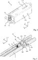
- FIG. 2 a perspective view of a pair of rails of a longitudinal adjuster formed by means of a first seat rail 2 and a second seat rail 4 is shown.
- a function basically provided by the longitudinal adjuster for setting a longitudinal position of the vehicle seat 1 can be actuated by means of a handle 200 which, as shown, is arranged on a transmission rod 204.
- an actuating lever 202 is arranged on the transmission rod 204, which is set up to act on a locking device of the respective pair of rails of the longitudinal adjuster in order to unlock it and to be able to adjust the vehicle seat 1 accordingly in the longitudinal direction x.
- a memory device which serves an easy-entry function and, when the same is actuated, records a longitudinal displacement of the first seat rail 2 relative to the second seat rail 4 and, if the memory position is repeated, blocks a further longitudinal displacement, in particular by means of a blocking element 14 blocked.
- Fig. 3 shows a perspective view of a first possible embodiment of a memory device 22 for actuation from below.
- a housing 26 is designed to be open in the direction of the locking element 14, so that an actuating arm 24 can engage a locking element 14 from below and control it in an upward movement.
- the actuation from below corresponds to the configuration of a return spring 18 as a compression spring, which drives the locking element 14 into the release position in a spring-loaded manner.
- the blocking element 14 can be brought into the blocking position by actuation by means of the actuating arm 24 against the force of the return spring 18.
- a second axle 31b and third axle 31c mounted in the housing 26 are shown in this illustration, which are shown below on the basis of FIG Figures 5a and 5b are described in more detail.
- Fig. 4 is the memory device 22 according to Fig. 3 shown in a second seat rail 4.
- the representation of Fig. 4 further shows that the memory device 22 is connected to a spindle-nut arrangement.
- the spindle-nut arrangement comprises a threaded spindle 214 including a spur gear 212 arranged on the end face, a nut 216 and a toothed segment 220 (see FIG Fig. 9 ).
- the spindle-nut arrangement is arranged in such a way that a spur gear 212 arranged at the end of the threaded spindle 214 reaches through the passage opening 210 of the housing 26 of the memory device 22 and is in operative connection with a gear 30 located inside the housing 26.
- FIG. 13 shows a schematic illustration of a transmission of the memory device 22 of FIG Fig. 4 as well as a spindle-nut arrangement in two different angles.
- a first gear wheel 32a is shown, which is in engagement with a toothed rack 28 to detect a longitudinal displacement of the memory device 22 arranged in the first seat rail 2 relative to a second seat rail 4.
- the schematically illustrated rack 28 is preferably arranged in a floor area of the second seat rail 4 and is firmly connected to the second seat rail 4.
- the first gear 32a, together with a second gear 32b, is arranged non-rotatably on a first axis 31a.
- the second gear 32b meshes with the third gear 32c.
- the third gear 32c, together with the fourth gear 32d is arranged non-rotatably on a second axis 31b.
- the fourth gear 32d meshes with the fifth gear 32e, which is mounted on the third axle 31c.
- the directions of rotation of the gears 32a to 32e are shown in FIG Figure 5a indicated accordingly by arrows.
- the radii of the first gear 32a, the second gear 32b, the third gear 32c, the fourth gear 32d, and the fifth gear 32e are selected in such a way that the rotational movement of the first gear wheel 32a is stepped down so that the fifth gear wheel 32e executes a maximum of one full revolution, preferably slightly less than one full revolution, corresponding to a maximum possible longitudinal displacement.
- memory devices 22 based on a transmission 30 are also conceivable, the gears 32a to 32e of which are adapted in such a way that a rotation of more than 360 ° of the fifth gear 32e, which generally corresponds to the last gear, is provided.
- the first gear wheel 32a has a larger radius than the second gear wheel 32b.
- the second gear 32b also has a smaller radius than the third gear 32c.
- the third gear 32c has a larger radius than the fourth gear 32d.
- the fourth gear 32d has a smaller radius than the fifth gear 32e.
- the third axis 31c serves to support a driver plate (not shown) and the actuating arm 24.
- the second axis 31b and the third axis 31c are - as in FIG Fig. 3 shown - stored in bearings provided in the housing 26 of the memory device 22.
- the first axle 31a is mounted on one end of the rocker 36, which in turn is mounted on the second axle 31b.
- a lever connected to the rocker 36 is also arranged on the second axis 31b.
- the rocker 36 is further connected to a tie rod 38, which serves to enable a longitudinal adjustment of the vehicle seat 1 in a new longitudinal seat position to be stored. This takes place in that the pull rod 38 pivots the rocker 36 about the second axis 31b and the first gear wheel 32a is lifted off the rack 28. Because of the lost contact between the first gear 32a and the rack 28, the memory device 22 can no longer detect any longitudinal displacement. This is only the case again when the pull rod 38 and, accordingly, the first gear wheel 32a are lowered.
- a reset spring not shown, is provided to provide a so-called reset function, by means of which the transmission 30 can be brought back into the initial state.
- the reset spring engages for this purpose, for example, on one of the gears 32a to 32e, preferably on one of the gears 32a, 32c, 32e, and rotates the gear 30 and the drive plate connected to the gear 30 back into the position which the gear 30 and the drive plate in the Have stored longitudinal seat position.
- the reset spring can be designed, for example, in the form of a spiral spring.
- the reset spring is preferably supported between an aforementioned gear wheel 32a to 32e and on a section fixed to the housing.
- the reset spring is preferably pretensioned when the first seat rail 2 is displaced by the rotation of the corresponding gear wheel 32a to 32e. If the gear 30 is then brought into freewheeling mode by lifting the first gear 32a by means of the tie rod 38 out of engagement with the rack 28, releasing the pretensioned reset spring causes the gear 30 to be reset; in other words, it causes the gear 30 to be reset An actuation of the pull rod 28 is preferably implemented by means of a reset lever 242 of a seat length adjustment mechanism described below.
- the face gear 212 arranged on the front side of the threaded spindle is in engagement with the third gear 32c of the transmission 30, so that a rotational movement corresponding to the displacement of the first seat rail 2 is picked up.
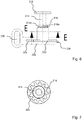
- the Figures 6 to 9 essentially show the spindle-nut arrangement with and without multifunctional part 222. Due to the high degree of correspondence between the parts shown and the common functional relationship, the Figures 6 to 9 jointly described below.
- the cross-sectional representation shown corresponds to a section plane EE from Fig. 6 .
- the threaded spindle 214 has a spur gear 212 arranged on the end face, which takes over a rotation of a corresponding counter gear of a transmission, in this case the third gear 32c of the transmission 30, of the memory device 22 and the threaded spindle 214 in one of the Longitudinal displacement of the first seat rail 2 relative to the second seat rail 4 offset corresponding rotation. Furthermore, the threaded spindle 214 has a stop 214a which, in the memory position, is in abutment with an edge 216a of a nut 216 mounted on an external thread of the threaded spindle 214. The nut 216 is in engagement with the external thread of the threaded spindle 214 via an internal thread.
- the nut also has 216 the outside has an external toothing oriented coaxially to an axis of the threaded spindle 214.
- This external toothing of the nut 216 is guided in an internal toothing of a section of a tooth segment 220, which is likewise oriented coaxially to the axis of the threaded spindle 214, in a corresponding coaxial direction.
- the sectional illustration shown along the axis of the threaded spindle 214 shows the radial sequence of the threaded spindle 214, nut 216 and section of tooth segment 220, which are mounted and / or guided one inside the other.
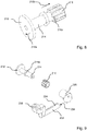
- Fig. 8 13 shows, in particular, an illustration of the threaded spindle 214 and the nut 216 in a state in which the nut 216 is removed from a stop 214a in the axial direction of the threaded spindle 214.
- the nut 216 On its end face facing the stop 214a of the threaded spindle 214, the nut 216 has an edge 216a that can be brought into contact with the stop 214a of the threaded spindle 214.
- the nut 216 is essentially inhibited from rotating about the axis of the threaded spindle 214 through the connection of its external toothing with the internal toothing of the section of the toothed segment 220 and is guided essentially axially displaceably in the toothed segment 220.
- the nut 216 is moved away from the stop 214a in the direction of the arrow 218b or towards the stop 214a in the opposite direction of rotation, depending on its connection with a thread of the threaded spindle 214.
- the toothed segment 220 is in operative connection with a toothing 224 of the multifunctional part 222.
- the toothing 224 is designed in the form of a toothed rack.
- the multifunctional part 222 has a first connection section 234 and a second connection section 236 opposite the first connection section 234.
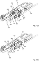
- Figures 10a and 10b each show a perspective view of the spindle-nut arrangement Fig. 9 .
- Figure 10a the spindle-nut arrangement is shown in a state in the memory position
- Figure 10b shows the spindle-nut arrangement outside of the memory position.
- FIG 10a the state in the memory position is shown in which the stop 214a of the threaded spindle 214 is in contact with the edge 216a of the nut 216 and the multifunctional part 222 is also held in the position shown.
- the threaded spindle 214 is in contact with the edge 216a of the nut 216 via its stop 214a and holds it in the position shown against a prestressing force acting on the multifunctional part 222.
- This pretensioning force can be generated, for example, by a spring (not shown) acting on the multifunctional part 222 and drives the multifunctional part 222 in the direction indicated by the arrow 225.
- a corresponding rotation of the threaded spindle 214 causes the toothed segment 220 to rotate via the stop 214a in contact with the edge 216a of the nut 216, so that the toothed segment 220 holds the multifunctional part 222 in the position shown against the pretensioning force.
- Figure 10b shows a state outside of the memory position, in which the first seat rail 2 has been displaced relative to the second seat rail 4 and the spur gear 212 has been correspondingly driven by the transmission 30 of the memory device 22.
- a displacement of the vehicle seat 1 away from the memory position causes a rotation of the threaded spindle 214 driven by a drive of the spur gear 212, so that, for example, during the first 60 ° to 90 ° rotation of the threaded spindle 214, the edge 216a of the nut 216 turns away Stop 214a follows. This is due to the prestressing force acting on the multifunctional part 222, which drives the nut 216 via the toothed segment 220 and thus rotates the edge 216a behind the stop 214a.
- the spur gear 212 rotates in the opposite direction driven and the nut 216 screws again in the direction of the stop 214a of the threaded spindle 214. If the nut 216 with the edge 216a arrives again shortly before reaching the memory position, corresponding to the last 60 ° to 90 ° rotation of the threaded spindle 214, in Contact with the stop 214a, the nut 216 and the toothed segment 220 are forced into a rotational movement in the same direction by the threaded spindle 214, which moves the multifunctional part 222 against the pretensioning force in the in Figure 10a position shown moved.
- Fig. 11 shows a perspective view of a memory device 22 for providing an easy-entry convenience function, as one of at least two possible functions that can be actuated by means of the multifunctional part 222.
- a first Bowden cable 230 is shown schematically, which is held in a first receptacle 231.
- the first Bowden cable 230 has a core which is enclosed by a sleeve (not designated in more detail), also not designated in more detail and which is guided via a deflection roller 266 and connected to a locking lever 258.
- the other end of the first Bowden cable 230 is operatively connected to the backrest 3 and is used to unlock the longitudinal adjustment, in particular the longitudinal adjuster, in that the locking of the longitudinal adjuster is triggered by folding the backrest 3 forwards using the first Bowden cable 230.
- the locking lever 258 is initially pivoted by the first Bowden cable 230 about a first pivot point 260 with its free end against a first stop 248.
- the actuating lever 202 is then moved along by the locking lever 258 supported on the stop 248 and acts in a manner known per se on a locking of the longitudinal adjuster (not shown in detail) and unlocks this locking of the longitudinal adjuster.
- a second Bowden cable 232 is also provided, the casing of which is held in a second receptacle 233 and the core of which is connected to the first connecting section 234 of the multifunctional part 222. If, after the backrest 3 has been folded forward and the longitudinal adjuster is unlocked as a result, the vehicle seat 1 is moved from a use position to an easy-entry position, the multifunctional part 222 of the transmission 30 of the memory device 22 is via the spindle nut -Arrangement and the tooth segment 220 powered. The multi-function part 222 actuates a lock for locking the folded backrest 3 by means of the second Bowden cable 232 connected to the first connecting section 234 unlocked. In this state, the vehicle seat 1 is freely displaceable forwards in the longitudinal direction.
- the multifunctional part 222 is driven again by the transmission 30 of the memory device 22 via the spindle-nut arrangement and the toothed segment 220, starting shortly before reaching the memory position, but in the opposite direction Direction than before.
- the second Bowden cable 232 releases the lock for locking the folded backrest 3, and the backrest 3 can be straightened up again when the memory position is reached, so that the vehicle seat 1 again assumes the position of use.
- the Figures 12a and 12b show a perspective illustration of a second embodiment of the device according to the invention, in particular a device for providing an easy-entry hold-open function, as one of at least two possible functions that can be actuated by means of the multifunctional part 222.
- This embodiment is used according to the invention when the longitudinal adjuster with easy-entry function does not have a lock for locking the folded backrest 3, for example in order to save material in the area of the backrest 3 and / or a backrest inclination adjustment to save costs and weight accordingly with fewer components and / or to be able to manufacture lighter material. If, accordingly, no lock is provided for locking the folded backrest 3, the backrest 3 can be erected again so that it can pivot freely in any longitudinal position of the displaced vehicle seat 1.
- the vehicle seat 1 can be moved out of the memory position in the direction of the easy-entry position become.
- the multifunctional part 222 is driven by the transmission 30 of the memory device 22 via the spindle-nut arrangement and the toothed segment 220.
- the multifunctional part 222 actuates the easy-entry hold-open function by means of a blocking lever 238 connected to the second connecting section 236, in particular a lug 240 formed on the blocking lever 238. If, as previously described, the actuating lever 202 is pivoted into a position that opens the locking of the longitudinal adjuster, moving the vehicle seat 1 causes the blocking lever 238 to be pivoted by the movement of the multifunctional part 222 into the radius of movement of the actuating lever 202 and the actuating lever 202 into the opening position, as shown in Fig.12b is shown.
- the backrest 3 can then be raised again in an advanced position of the vehicle seat 1 without the locking of the longitudinal adjuster being locked again by the yielding of the first Bowden cable 230, since the actuating lever 202 is secured in the unlocking position.
- the vehicle seat 1 can be freely displaced in the longitudinal direction up to the easy-entry position and back into the memory position.
- the longitudinal adjustment is only automatically locked again when the memory position is reached.
- the lug 240 is pivoted back together with the blocking lever 238 by a corresponding movement of the multifunctional part 222 and releases the actuating lever 202, whereby the locking of the longitudinal adjuster is locked again.
- the representation of Figure 12b a housing 226 for the spindle-nut assembly and the multifunctional part 222 can be found.
- the multifunctional part 222 is mounted in corresponding recesses and guides in the housing 226.
Landscapes
- Engineering & Computer Science (AREA)
- Aviation & Aerospace Engineering (AREA)
- Transportation (AREA)
- Mechanical Engineering (AREA)
- Seats For Vehicles (AREA)
Description
- Die Erfindung betrifft eine Vorrichtung für einen Fahrzeugsitz mit den Merkmalen des Oberbegriffs des Anspruchs 1, sowie einen Fahrzeugsitz.
- Im Stand der Technik sind verschiedene Easy-Entry-Systeme bekannt, welche einen erleichterten Einstieg in eine zweite Sitzreihe eines Fahrzeuges ermöglichen. Das Easy-Entry-System ist durch einen Entriegelungshebel, welcher üblicherweise an einer Rückenlehne des Fahrzeugsitzes angeordnet ist, betätigbar, wodurch die Rückenlehne des Fahrzeugsitzes aus einem Einstiegsbereich schwenkt. Ist der Fahrzeugsitz auf Schienen angeordnet, kann der Fahrzeugsitz bei Betätigung des Entriegelungshebels zusätzlich oder alternativ in Fahrtrichtung aus dem Einstiegsbereich heraus verschiebbar sein.
- In an sich bekannter Weise ermöglicht eine Easy-Entry-Verstellvorrichtung für einen Fahrzeugsitz eine Verstellbarkeit des Fahrzeugsitzes zwischen einer Gebrauchsposition und einer Easy-Entry-Position. Eine solche Verstellbarkeit ist insbesondere für solche Fahrzeuge besonders vorteilhaft, die lediglich eine Türe pro Fahrzeugseite haben. Beim Überführen des Fahrzeugsitzes von der Gebrauchsposition in die Easy-Entry-Position wird sowohl ein Lehnenbeschlag der Verstellvorrichtung, als auch eine Sitzlängsverriegelung der Verstellvorrichtung gelöst. Das Lösen des Lehnenbeschlags ermöglicht ein Verschwenken der Sitzlehne des Fahrzeugsitzes nach vorn in Richtung eines Sitzteils des Fahrzeugsitzes, während das Lösen der Sitzlängsverriegelung ein Vorschieben des gesamten Fahrzeugsitzes in Fahrtrichtung ermöglicht. Ein Fahrzeuginsasse erlangt somit Zugang zu den Rücksitzen des Fahrzeugs.
- Aus der
DE 10 2011 011 766 A1 sind ein gattungsgemäßer Längseinsteller sowie ein gattungsgemäßer Fahrzeugsitz bekannt. Der Längseinsteller umfasst zwei Schienenpaare mit jeweils zwei relativ zueinander verschiebbaren Sitzschienen, nämlich einer Oberschiene und einer Unterschiene, welche einander wechselseitig umgreifen. Die Oberschiene ist relativ zu der Unterschiene innerhalb eines Komforteinstellbereichs und darüber hinaus in eine Easy-Entry-Stellung verschiebbar. - Aus der
DE 10 2004 057 901 B3 ist ein Längseinsteller für einen Fahrzeugsitz bekannt, mit frei schwenkbarer Lehne, mit einer ersten Sitzschiene, einer zweiten Sitzschiene, relativ zu welcher die erste Sitzschiene in Längsrichtung verschiebbar ist, einer Verriegelungsvorrichtung zum Verriegeln des Längseinstellers, einer der ersten Sitzschiene zugeordneten und mit der zweiten Sitzschiene zusammenwirkenden Memoryvorrichtung, welche eine eingestellte Sitzlängsposition speichert, die durch eine beim Freischwenken der Lehne vorgenommene Längsverschiebung des Fahrzeugsitzes verlassen und beim Zurückschieben wieder eingenommen wird, und einer der ersten Sitzschiene zugeordneten Ansteuervorrichtung, welche die Memoryvorrichtung zum Zurücksetzen und die Verriegelungsvorrichtung zum Entriegeln ansteuert, wobei die Ansteuervorrichtung relativ zur ersten Sitzschiene in Längsrichtung eingeschränkt beweglich angeordnet ist. - Aus der
WO 2014/055083 A1 ist eine Führungsbahn-Anordnung bekannt, enthaltend eine Memory-Anordnung, die in einen Eingriffszustand versetzt werden kann, um eine von einem Benutzer gewählte Position einzustellen. Wenn sich die Memory-Anordnung in einem Eingriffszustand und an der von einem Benutzer gewählten Position befindet, setzt die Memory-Anordnung Bewegung einer ersten Schiene relativ zu einer zweiten Schiene in einer Rückwärts-Richtung Widerstand entgegen. Wenn sich die Memory-Anordnung in dem Eingriffszustand und an der von einem Benutzer gewählten Position befindet und sich die zweite Schiene relativ zu der ersten Schiene in einer Vorwärts-Richtung bewegt, wird die Memory-Anordnung in der Rückwärts-Richtung relativ zu der zweiten Schiene an eine erste Position verschoben. - Der Erfindung liegt die Aufgabe zu Grunde, eine Vorrichtung für einen Fahrzeugsitz der eingangs genannten Art zu verbessern, insbesondere eine modulare bedarfsweise Bereitstellung einer Easy-Entry-Komfort-Funktion sowie einer Easy-Entry-Offenhaltefunktion zu ermöglichen sowie einen entsprechenden Fahrzeugsitz bereitzustellen.
- Diese Aufgabe wird erfindungsgemäß gelöst durch eine Vorrichtung für einen Fahrzeugsitz, welcher einen Sitzteil und eine Lehne aufweist, und dessen Sitzteil mit einer ersten Sitzschiene eines Längseinstellers verbunden ist. Die erste Sitzschiene des Längseinstellers ist in einer strukturfesten zweiten Sitzschiene des Längseinstellers in Längsrichtung verschiebbar geführt. Der Fahrzeugsitz ist für einen vereinfachten Zugang zu den rückwärtigen Sitzen aus der Gebrauchsstellung in eine Easy-Entry-Stellung überführbar, wenn eine Verriegelung des Längseinstellers des Fahrzeugsitzes durch ein Vorklappen der Lehne entriegelt ist. Ferner ist eine Memory-Vorrichtung vorgesehen, welche eine Verschiebung der ersten Sitzschiene relativ zur zweiten Sitzschiene erfasst. Ebenso weist die Vorrichtung ein mit der Memory-Vorrichtung in Verbindung stehendes Mehrfunktionsteil auf, welches mittels einem zusätzlichen Bauteil eingerichtet ist, eine Easy-Entry-Komfort-Funktion oder eine Easy-Entry-Offenhaltefunktion bereitzustellen.
- Unter einer Easy-Entry-Funktion ist allgemein zu verstehen, dass ein Fahrzeugsitz zum erleichterten Einsteigen in eine hintere Sitzreihe aus einer Gebrauchsstellung, durch Vorklappen der Lehne sowie ein Verschieben in Längsrichtung, in eine sogenannte Easy-Entry-Stellung überführbar ist, um dem einsteigenden Fahrgast möglichst viel Platz zwischen dem Fahrzeugsitz und der hinteren Sitzreihe bereitzustellen. Zum Aktivieren der Easy-Entry-Funktion wird ein Entriegeln der Längsverstellung in an sich bekannter Weise durch entsprechendes Vorklappen der Lehne ausgelöst. Wird die Lehne beim Zurückverschieben des Fahrzeugsitzes jedoch vor Erreichen der Memory-Position wieder aufgerichtet, so verriegelt die Längsverstellung vorzeitig. Zur Verhinderung eines vorzeitigen Aufrichtens der Lehne kann beispielsweise eine Verriegelung vorgesehen sein, welche die Lehne in der vorgeklappten Stellung arretiert. Diese Verriegelung muss jedoch in bekannter Weise beim Erreichen der Memory-Position durch ein manuelles Betätigen eines Handgriffs oder Hebels von Benutzer gelöst werden, um die Lehne wieder in eine Gebrauchsstellung aufrichten zu können. Die
DE 10 2008 008 935 B3 , deren diesbezüglicher Offenbarungsgehalt ausdrücklich einbezogen wird, bezeichnet eine derartige Verriegelung zur Arretierung der vorgeklappten Lehne als Feststellklinke und beschreibt diese detailliert in ihrer Funktion. - Unter einer Easy-Entry-Komfort-Funktion im Sinne der Erfindung ist allgemein zu verstehen, dass, im Falle eines Längseinstellers mit Easy-Entry-Funktion und einer vorgesehenen Verriegelung zur Arretierung der vorgeklappten Lehne, beim Erreichen der Memory-Position selbstständig eine Entriegelung der Lehne ausgelöst wird. Dies erspart dem Benutzer ein erneutes manuelles Betätigen eines Handgriffs oder Hebels zum manuellen Lösen der zuvor beschriebenen Verriegelung zur Arretierung der vorgeklappten Lehne.
- Unter einer als Easy-Entry-Offenhaltefunktion bezeichneten Funktion im Sinne der Erfindung ist allgemein zu verstehen, dass im Falle eines Längseinstellers mit Easy-Entry-Funktion ohne Verriegelung zur Arretierung der vorgeklappten Lehne, nach einem Verlassen der Memory-Position die Verriegelung der Längsverstellung permanent in dem geöffneten entriegelten Zustand gehalten. Selbst dann, wenn die Lehne beim Zurückverschieben des Fahrzeugsitzes, jedoch vor Erreichen der Memory-Position, wieder aufgerichtet wird, bleibt die Verriegelung der Längsverstellung geöffnet und der Fahrzeugsitz ist trotz vorzeitig aufgerichteter Lehne weiter zurück schiebbar, bis in die Memory-Position. Beim Erreichen der Memory-Position wird die Längsverstellung wieder automatisch verriegelt.
- Allgemein weist der Längseinsteller zusätzlich wenigstens ein von dem Sperrelement der Memory-Vorrichtung zu unterscheidendes weiteres Verriegelungselement einer Verriegelung des Längseinstellers auf, welches dazu eingerichtet ist, die sitzfeste erste Sitzschiene in Bezug auf die strukturfeste zweite Sitzschiene zu verriegeln. Zur genaueren Unterscheidung sei darauf hingewiesen, dass das Sperrelement lediglich zur Blockierung einer Bewegung der ersten Sitzschiene relativ zur zweiten Sitzschiene beim Erreichen der gespeicherten Memory-Position eingerichtet ist, während das Verriegelungselement in an sich bekannter Weiser einer Einstellung einer Sitzlängsposition dient und zur Aufnahme von bei einem Frontalaufprall auftretenden Kräften eingerichtet ist.
- Beim Erreichen der gespeicherten Memory-Position erfolgt eine Blockierung der ersten Sitzschiene in der zweiten Sitzschiene mittels des Sperrelements. Zum Betätigen des Sperrelements weist die Memory-Vorrichtung einen mit dem Getriebe wirkverbundenen und relativ zu dem Getriebe beweglichen Betätigungsarm auf. Spätestens bei Erreichen der gespeicherten Sitzlängsposition übt das Getriebe ein Steuermoment auf den Betätigungsarm aus, aufgrund dessen der Betätigungsarm das Sperrelement ansteuert. Unter "ansteuern" kann hierbei allgemein verstanden werden, dass mittels einer Bewegung des Betätigungsarmes eine Veränderung der resultierenden auf das Sperrelement wirkenden Kraft erzielt wird, in Folge dessen das Sperrelement in eine Blockierstellung bewegt wird.
- Hierbei wird in vorteilhafter Weise die Anzahl an Gleichteilen in der modularen Vorrichtung erhöht und die Easy-Entry-Komfort-Funktion und eine Easy-Entry-Offenhaltefunktion mit jeweils einem optionalen, zusätzlichen Bauteil ermöglicht. Eine zeitgleiche Bereitstellung beider Funktionen ist nicht beabsichtigt, jedoch ausdrücklich auch nicht ausgeschlossen. Hierdurch ergeben sich weiter fertigungstechnische Synergieeffekte, welche weiter vorteilhaft die Wirtschaftlichkeit in der Herstellung der Vorrichtung weiter verbessert.
- Vorteilhafte Ausgestaltungen, welche einzeln oder in Kombination miteinander eingesetzt werden können, sind Gegenstand der Unteransprüche.
- Gemäß einer möglichen Ausgestaltung der Vorrichtung weist die Memory-Vorrichtung ein Getriebe auf, welches eine Verschiebung der ersten Sitzschiene relativ zur zweiten Sitzschiene erfasst.
- Das Mehrfunktionsteil kann an den in Längsrichtung betrachteten Enden einen ersten Verbindungabschnitt und einen dem ersten Verbindungsabschnitt gegenüberliegenden zweiten Verbindungsabschnitt aufweisen.
- Das zusätzliche Bauteil kann beispielsweise ein Bowdenzug sein, welcher mit einer Verriegelung zur Arretierung der vorgeklappten Lehne in Wirkverbindung steht. Der Bowdenzug kann mit dem ersten Verbindungsabschnitt des Mehrfunktionsteils verbunden sein.
- Das zusätzliche Bauteil kann beispielsweise ein Blockierhebel sein, welcher eingerichtet ist, die Verriegelung des Längseinstellers im entriegelten Zustand zu sichern. Das Mehrfunktionsteil kann bevorzugt über dem zweiten Verbindungsabschnitt mit dem Blockierhebel verbundenen sein. Der Blockierhebel kann von der Bewegung des Mehrfunktionsteils in den Bewegungsradius des Betätigungshebels verschwenkbar sein. Ferner kann der Blockierhebel eine angeformte Nase aufweisen.
- Die Memory-Vorrichtung kann mit einer Spindel-Mutter-Anordnung in Verbindung stehen. Die Spindel-Mutter-Anordnung kann eine Gewindespindel samt stirnseitig angeordnetem Stirnzahnrad, eine Mutter sowie ein Zahnsegment umfassen. Das Zahnsegment der Spindel-Mutter-Anordnung kann mit einer Verzahnung des Mehrfunktionsteils in Wirkverbindung stehen, um dieses anzutreiben. Ferner kann es vorgesehen sein, dass die Verzahnung in Form einer Zahnstange ausgebildet ist.
- Ferner wird die Aufgabe erfindungsgemäß gelöst, durch einen Fahrzeugsitz mit wenigstens einer Vorrichtung gemäß der vorherigen Beschreibung.
- Im Folgenden ist die Erfindung anhand von in den Figuren dargestellten vorteilhaften Ausführungsbeispielen näher erläutert. Die Erfindung ist jedoch nicht auf diese Ausführungsbeispiele beschränkt. Es zeigen:
- Fig. 1:
- eine schematische Darstellung eines Fahrzeugsitzes,
- Fig. 2:
- eine perspektivische Darstellung eines Schienenpaares eines Längseinstellers mit einer Memory-Vorrichtung,
- Fig. 3:
- eine perspektivische Darstellung einer möglichen Ausgestaltung einer Memory-Vorrichtung,
- Fig. 4:
- eine ausschnittsweise Darstellung einer Memory-Vorrichtung in einer zweiten Sitzschiene,
- Fig. 5a:
- eine schematische Darstellung eines Getriebes der Memory-Vorrichtung von
Fig. 4 sowie einer Spindel-Mutter-Anordnung, - Fig. 5b:
- eine schematische Darstellung des Getriebes der Memory-Vorrichtung von
Fig. 5a aus einem unterschiedlichen Blickwinkel, - Fig. 6:
- eine Draufsicht auf eine Spindel-Mutter-Anordnung,
- Fig. 7:
- eine Querschnittsdarstellung durch die Spindel-Mutter-Anordnung von
Fig. 6 entlang der Schnittebene E-E, - Fig. 8:
- eine perspektivische Darstellung eines Teils der Spindel-Mutter-Anordnung aus
Fig. 6 , - Fig. 9:
- eine Ansicht einer Explosionsdarstellung der Spindel-Mutter-Anordnung aus
Fig. 6 mit einem Funktionselement, - Fig. 10a:
- eine perspektivische Darstellung der zusammengesetzten Spindel-Mutter-Anordnung aus
Fig. 9 in einem Zustand in der Memory-Position, - Fig. 10b:
- eine perspektivische Darstellung der Spindel-Mutter-Anordnung aus
Fig. 10a in einem Zustand außerhalb der Memory-Position, - Fig. 11:
- eine perspektivische Darstellung einer Memory-Vorrichtung zur Bereitstellung einer Komfort-Funktion,
- Fig. 12a:
- eine perspektivische Darstellung einer Memory-Vorrichtung zur Bereitstellung einer Offenhaltefunktion in der Memory-Position, und
- Fig. 12b:
- eine perspektivische Darstellung einer Memory-Vorrichtung zur Bereitstellung einer Offenhaltefunktion außerhalb der Memory-Position.
- Die Zeichnungen werden nachfolgend unter Verwendung von drei senkrecht zueinander verlaufenden Raumrichtungen beschrieben. Eine Längsrichtung x verläuft bei einem im Fahrzeug eingebauten Fahrzeugsitz 1 weitgehend horizontal und vorzugsweise parallel zu einer Fahrzeuglängsrichtung, die der gewöhnlichen Fahrtrichtung des Fahrzeuges entspricht. Eine zu der Längsrichtung x senkrecht verlaufende Querrichtung y ist im Fahrzeug ebenfalls horizontal ausgerichtet und verläuft parallel zu einer Fahrzeugquerrichtung. Eine Vertikalrichtung z verläuft senkrecht zu der Längsrichtung x und senkrecht zu der Querrichtung y. Bei einem im Fahrzeug eingebauten Fahrzeugsitz 1 verläuft die Vertikalrichtung z parallel zu der Fahrzeughochachse.
- Die verwendeten Positionsangaben und Richtungsangaben, wie beispielsweise vorne, hinten, oben und unten beziehen sich auf eine Blickrichtung eines im Fahrzeugsitz 1 sitzenden Insassen in normaler Sitzposition, wobei der Fahrzeugsitz 1 im Fahrzeug eingebaut, in einer zur Personenbeförderung geeigneten Gebrauchsposition mit aufrecht stehender Lehne 3 und wie üblich in Fahrtrichtung ausgerichtet ist. Der Fahrzeugsitz 1 kann jedoch auch in abweichender Ausrichtung, beispielsweise quer zur Fahrtrichtung verbaut werden.
- Der in
Fig. 1 gezeigte Fahrzeugsitz 1 ist in einer Gebrauchsstellung mit aufgerichteter Lehne 3 auf einem Längseinsteller montiert. Der Längseinsteller weist eine erste Sitzschiene 2 und eine zweite Sitzschiene 4 auf, relativ zu welcher die erste Sitzschiene 2 in Längsrichtung verschiebbar ist. Der Fahrzeugsitz 1 ist hierbei mit der ersten Sitzschiene 2 fest verbunden. Die zweite Sitzschiene 4 ist üblicher Weise mit einem nicht dargestellten Fahrzeugboden und/oder einer Fahrzeugstruktur verbunden. Der Fahrzeugsitz 1 ist zusammen mit der sitzfesten, ersten Sitzschiene 2 relativ zu der strukturfesten, zweiten Sitzschiene 4 in Längsrichtung x verschiebbar. Vorzugsweise weist der Fahrzeugsitz 1 zwei im Wesentlichen symmetrisch zu einer Mittelebene, die senkrecht zur Querrichtung y verläuft, angeordnete Längseinsteller auf. - In
Fig. 2 ist eine perspektivische Darstellung eines mittels einer ersten Sitzschiene 2 und einer zweiten Sitzschiene 4 gebildeten Schienenpaares eines Längseinstellers gezeigt. Eine von dem Längseinsteller grundsätzlich bereitgestellte Funktion zum Einstellen einer Sitzlängsposition des Fahrzeugsitzes 1 ist mittels eines Handgriffs 200, welcher wie dargestellt an einer Übertragungsstange 204 angeordnet ist, betätigbar. Ferner ist ein Betätigungshebel 202 an der Übertragungsstange 204 angeordnet, welcher dazu eingerichtet ist, auf eine Verriegelungsvorrichtung des jeweiligen Schienenpaares des Längseinstellers zu wirken, um dieses zu entriegeln und den Fahrzeugsitz 1 entsprechend in Längsrichtung x verstellen zu können. Ferner ist eine Memory-Vorrichtung vorgesehen, welche einer Easy-Entry-Funktion dient und beim Betätigen derselben eine Längsverschiebung der ersten Sitzschiene 2 relativ zur zweiten Sitzschiene 4 längenmäßig erfasst und im Falle eines wiederholten Einnehmens der Memory-Position eine weitere Längsverschiebung blockiert, insbesondere mittels eines Sperrelements 14 blockiert. -
Fig. 3 zeigt eine perspektivische Darstellung einer ersten möglichen Ausgestaltung einer Memory-Vorrichtung 22 zur Betätigung von unten.Fig. 3 zeigt, dass ein Gehäuse 26 in Richtung des Sperrelements 14 offen ausgestaltet ist, so dass ein Betätigungsarm 24 von unten her an einem Sperrelement 14 angreifen und dieses in einer nach oben gerichteten Bewegung ansteuern kann. Die Betätigung von unten entspricht der Ausgestaltung einer Rückstellfeder 18 als Druckfeder, welche das Sperrelement 14 federbelastet in die Freigabestellung treibt. Das Sperrelement 14 ist durch die Betätigung mittels des Betätigungsarms 24 entgegen der Kraft der Rückstellfeder 18 in die Blockierstellung bringbar. Ferner sind in dieser Darstellung eine im Gehäuse 26 gelagerte zweite Achse 31b und dritte Achse 31c gezeigt, welche nachfolgend anhand derFiguren 5a und 5b näher beschrieben werden. - In
Fig. 4 ist die Memory-Vorrichtung 22 gemäßFig. 3 in einer zweiten Sitzschiene 4 gezeigt. Die Darstellung vonFig. 4 zeigt weiter, dass die Memory-Vorrichtung 22 mit einer Spindel-Mutter-Anordnung in Verbindung steht. Die Spindel-Mutter-Anordnung umfasst, eine Gewindespindel 214 samt stirnseitig angeordnetem Stirnzahnrad 212, eine Mutter 216 sowie ein Zahnsegment 220 (sieheFig. 9 ). Die Spindel-Mutter-Anordnung ist hierbei derart angeordnet, dass ein stirnseitig an der Gewindespindel 214 angeordnetes Stirnzahnrad 212 durch die Durchtrittsöffnung 210 des Gehäuses 26 der Memory-Vorrichtung 22 hindurchgreift und mit einem innerhalb des Gehäuses 26 befindlichen Getriebe 30 in Wirkverbindung steht. - Die
Figuren 5a und 5b zeigen eine schematische Darstellung eines Getriebes der Memory-Vorrichtung 22 vonFig. 4 sowie einer Spindel-Mutter-Anordnung in zwei unterschiedlichen Blickwinkeln. - Anhand der
Figuren 5a und 5b wird nachfolgend der Aufbau und die allgemeine Funktionsweise einer auf einem Getriebe 30 basierenden beispielhaften Memory-Vorrichtung 22 beschrieben. Hierbei ist ein erstes Zahnrad 32a gezeigt, welches zur Erfassung einer Längsverschiebung der in der ersten Sitzschiene 2 angeordneten Memory-Vorrichtung 22 relativ zu einer zweiten Sitzschiene 4, mit einer Zahnstange 28 in Eingriff steht. Die schematisch dargestellte Zahnstange 28 ist bevorzugt in einem Bodenbereich der zweiten Sitzschiene 4 angeordnet und fest mit der zweiten Sitzschiene 4 verbunden. - Eine Rotationsbewegung des ersten Zahnrades 32a entspricht demnach der Längsverschiebung. Das erste Zahnrad 32a ist zusammen mit einem zweiten Zahnrad 32b drehfest auf einer ersten Achse 31a angeordnet. Das zweite Zahnrad 32b steht in Eingriff mit dem dritten Zahnrad 32c. In gleicher Weise ist das dritte Zahnrad 32c zusammen mit dem vierten Zahnrad 32d drehfest auf einer zweiten Achse 31b angeordnet. Das vierte Zahnrad 32d steht in Eingriff mit dem fünften Zahnrad 32e, welches auf der dritten Achse 31c gelagert ist. Die Rotationsrichtungen der Zahnräder 32a bis 32e sind in
Fig. 5a entsprechend durch Pfeile angedeutet. - Die Radien des ersten Zahnrades 32a, des zweiten Zahnrades 32b, des dritten Zahnrades 32c, des vierten Zahnrades 32d und des fünften Zahnrades 32e sind derart gewählt, dass eine stufenweise Untersetzung der Rotationsbewegung des ersten Zahnrades 32a erfolgt, so dass entsprechend einer maximal möglichen Längsverschiebung das fünfte Zahnrad 32e maximal eine volle Umdrehung, bevorzugt etwas weniger als eine volle Umdrehung, ausführt. Es sind jedoch ebenso auf einem Getriebe 30 basierende Memory-Vorrichtungen 22 denkbar, deren Zahnräder 32a bis 32e derart angepasst sind, dass eine Drehung von mehr als 360° des fünften Zahnrades 32e, welches allgemein dem letzten Zahnrad entspricht, vorgesehen sind. Vorliegend weist das erste Zahnrad 32a einen größeren Radius als das zweite Zahnrad 32b auf. Das zweite Zahnrad 32b weist ferner einen kleineren Radius als das dritte Zahnrad 32c auf. Das dritte Zahnrad 32c weist einen größeren Radius als das vierte Zahnrad 32d auf. Das vierte Zahnrad 32d weist einen kleineren Radius als das fünfte Zahnrad 32e auf. Ferner dient die dritte Achse 31c zu Lagerung einer nicht dargestellten Mitnehmerscheibe sowie des Betätigungsarms 24.
- Die zweite Achse 31b und die dritte Achse 31c sind - wie in
Fig. 3 gezeigt - in vorgesehenen Lagerungen im Gehäuse 26 der Memory-Vorrichtung 22 gelagert. Die erste Achse 31a ist an einem Ende der Schwinge 36 gelagert, welche wiederum auf der zweiten Achse 31b gelagert ist. Auf der zweiten Achse 31b ist ferner ein mit der Schwinge 36 in Verbindung stehender Hebel angeordnet. Die Schwinge 36 ist weiter mit einer Zugstange 38 verbunden, welche dazu dient, eine Längseinstellung des Fahrzeugsitzes 1 in eine neue zu speichernde Sitzlängsposition zu ermöglichen. Dies erfolgt dadurch, dass die Zugstange 38 die Schwinge 36 um die zweite Achse 31b verschwenkt und hierbei das erste Zahnrad 32a von der Zahnstange 28 abgehoben wird. Aufgrund des verlorenen Kontakts zwischen erstem Zahnrad 32a und Zahnstange 28 kann die Memory-Vorrichtung 22 keine Längsverschiebung mehr erfassen. Dies ist erst wieder der Fall, wenn die Zugstange 38 und dementsprechend das erste Zahnrad 32a abgesenkt werden. - Ferner ist zur Bereitstellung einer sogenannten Reset-Funktion, mittels welcher das Getriebe 30 wieder in den Ausgangszustand bringbar ist, eine nicht dargestellte Reset-Feder vorgesehen. Die Reset-Feder greift hierzu beispielsweise an einem der Zahnräder 32a bis 32e, vorzugsweise an einem der Zahnräder 32a, 32c, 32e, an und dreht das Getriebe 30 sowie die mit dem Getriebe 30 verbundene Mitnehmerscheibe in die Stellung zurück, welche das Getriebe 30 und die Mitnehmerscheibe in der gespeicherten Sitzlängsposition aufweisen. Die Reset-Feder kann beispielsweise in Form einer Spiralfeder ausgestaltet sein. Die Reset-Feder stützt sich bevorzugt zwischen einem zuvor genannten Zahnrad 32a bis 32e und an einem gehäusefesten Abschnitt ab. Die Reset-Feder wird bevorzugt bei einem Verschieben der ersten Sitzschiene 2 von der Drehung des entsprechenden Zahnrades 32a bis 32e vorgespannt. Wenn anschließend das Getriebe 30 durch Anheben des ersten Zahnrades 32a mittels der Zugstange 38 außer Eingriff mit der Zahnstange 28 in den Freilauf gebracht wird, bewirkt ein Entspannen der vorgespannten Reset-Feder ein Rückstellen des Getriebes 30, anders ausgedrückt bewirkt es einen Reset des Getriebes 30. Eine Betätigung der Zugstange 28 ist bevorzugt mittels eines Reset-Hebels 242 eines nachfolgend beschriebenen Sitzlängsverstell-Mechanismus realisiert.
- Wie ferner in
Fig. 5a gezeigt ist, steht das stirnseitig an der Gewindespindel angeordnete Stirnzahnrad 212 mit dem dritten Zahnrad 32c des Getriebes 30 in Eingriff, so dass eine der Verschiebung der ersten Sitzschiene 2 entsprechende Rotationsbewegung abgegriffen wird. - Die
Figuren 6 bis 9 zeigen im Wesentlichen die Spindel-Mutter-Anordnung mit und ohne Mehrfunktionsteil 222. Aufgrund der hohen Übereinstimmung der gezeigten Teile sowie dem gemeinsamen funktionalen Zusammenhang werden dieFiguren 6 bis 9 nachfolgend gemeinsam beschrieben. Die inFig. 7 dargestellte Querschnittsdarstellung entspricht einer Schnittebene E-E ausFig. 6 . - Die Gewindespindel 214 weist ein stirnseitig angeordnetes Stirnzahnrad 212 auf, welches eine durch eine Längsverschiebung der ersten Sitzschiene 2 erzeugte Drehung eines entsprechenden Gegenzahnrades eines Getriebes, vorliegend des dritten Zahnrads 32c des Getriebes 30, der Memory-Vorrichtung 22 übernimmt und die Gewindespindel 214 in eine der Längsverschiebung der ersten Sitzschiene 2 relativ zur zweiten Sitzschiene 4 entsprechende Drehung versetzt. Ferner weist die Gewindespindel 214 einen Anschlag 214a auf, welche in der Memory-Position in Anschlag mit einer Kante 216a einer auf einem Außengewinde der Gewindespindel 214 gelagerten Mutter 216 ist. Die Mutter 216 ist über ein Innengewinde mit dem Außengewinde der Gewindespindel 214 in Eingriff. Ferner weist die Mutter 216 auf der Außenseite eine koaxial zu einer Achse der Gewindespindel 214 orientierte Außenverzahnung auf. Diese Außenverzahnung der Mutter 216 ist in einer entsprechend ebenfalls koaxial zur Achse der Gewindespindel 214 orientierten Innenverzahnung eines Abschnitts eines Zahnsegments 220 in entsprechend dieser koaxialen Richtung geführt. Die in
Fig. 7 gezeigte Schnittdarstellung entlang der Achse der Gewindespindel 214 zeigt die radiale Folge der ineinander gelagerten und/oder geführten Gewindespindel 214, Mutter 216 und Abschnitt des Zahnsegments 220. -
Fig. 8 zeigt insbesondere eine Darstellung der Gewindespindel 214 und der Mutter 216 in einem Zustand, in welchem die Mutter 216 in axialer Richtung der Gewindespindel 214 von einen Anschlag 214a entfernt ist. Die Mutter 216 weist an ihrer dem Anschlag 214a der Gewindespindel 214 zugewandten Stirnseite eine mit dem Anschlag 214a der Gewindespindel 214 in Anlage bringbare Kante 216a auf. Die Mutter 216 ist durch die Verbindung ihrer Außenverzahnung mit der Innenverzahnung des Abschnitts des Zahnsegments 220 in einer Rotation um die Achse der Gewindespindel 214 im Wesentlichen gehemmt und im Wesentlichen axial verschieblich in dem Zahnsegment 220 geführt. Dreht sich die Gewindespindel 214 in dem gezeigten Zustand entsprechend dem Pfeil 218a um ihre Drehachse, wird die Mutter 216 entsprechend ihrer Verbindung mit einem Gewinde der Gewindespindel 214 in Richtung des Pfeils 218b von dem Anschlag 214a weg oder bei entgegengesetzter Drehrichtung auf diesen zu bewegt. - Das Zahnsegment 220 steht mit einer Verzahnung 224 des Mehrfunktionsteils 222 in Wirkverbindung. Die Verzahnung 224 ist in Form einer Zahnstange ausgebildet. Das Mehrfunktionsteil 222 weist an den in Längsrichtung der Verzahnung 224 betrachteten Enden einen ersten Verbindungabschnitt 234 und einen dem ersten Verbindungsabschnitt 234 gegenüberliegenden zweiten Verbindungsabschnitt 236 auf.
-
Fig. 10a und Fig. 10b zeigen je eine perspektivische Darstellung der Spindel-Mutter-Anordnung ausFig. 9 . InFig. 10a ist die Spindel-Mutter-Anordnung in einem Zustand in der Memory-Position gezeigt, wohingegenFig. 10b die Spindel-Mutter-Anordnung außerhalb der Memory-Position zeigt. - In
Fig. 10a ist der Zustand in der Memory-Position dargestellt, in welchem der Anschlag 214a der Gewindespindel 214 in Kontakt mit der Kante 216a der Mutter 216 ist und das Mehrfunktionsteil 222 ebenso in der dargestellten Position gehalten ist. In diesem Zustand steht die Gewindespindel 214 über ihren Anschlag 214a mit der Kante 216a der Mutter 216 in Kontakt und hält diese entgegen einer auf das Mehrfunktionsteil 222 wirkende Vorspannkraft in der dargestellten Stellung. Diese Vorspannkraft kann beispielsweise durch eine nicht dargestellte, auf das Mehrfunktionsteil 222 wirkende Feder erzeugt sein und treibt das Mehrfunktionsteil 222 in die mit dem Pfeil 225 angezeigte Richtung. Eine entsprechende Rotation der Gewindespindel 214 bewirkt in diesem Zustand über den in Kontakt mit der Kante 216a der Mutter 216 befindlichen Anschlag 214a eine Drehung des Zahnsegments 220, so dass das Zahnsegment 220 das Mehrfunktionsteil 222 entgegen der Vorspannkraft in der gezeigte Stellung hält. -
Fig. 10b zeigt hingegen einen Zustand außerhalb der Memory-Position, in welchem die erste Sitzschiene 2 relativ zur zweiten Sitzschiene 4 verschoben wurde und das Stirnzahnrad 212 durch das Getriebe 30 der Memory-Vorrichtung 22 entsprechend angetrieben worden ist. Eine Verschiebung des Fahrzeugsitzes 1 von der Memory-Position weg bewirkt eine durch einen Antrieb des Stirnzahnrades 212 angetriebene Rotation der Gewindespindel 214, so dass beispielsweise während der ersten 60° bis 90°-Drehung der Gewindespindel 214 die Kante 216a der Mutter 216 dem sich wegdrehenden Anschlag 214a folgt. Dies ist der auf das Mehrfunktionsteil 222 wirkenden Vorspannkraft geschuldet, welche die Mutter 216 über das Zahnsegment 220 antriebt und somit die Kante 216a dem Anschlag 214a hinterherdreht. Erst wenn das Mehrfunktionsteil 222 sowie auch das Zahnsegment 220 in die dargestellte Stellung gelangt sind, erfolgt eine Drehung der weiterhin angetriebenen Gewindespindel 214 relativ zur Mutter 216, so dass die Kante 216a der Mutter 216 den Kontakt zum Anschlag 214a verliert. Hierbei bewegt sich die Mutter 216 über ein Gewinde der Gewindespindel 214 in Richtung des Pfeils 218b von dem Anschlag 214a weg und weiter in das Zahnsegment 220 hinein. - Erfolgt anschließend eine Verschiebung des Fahrzeugsitzes 1 zurück in Richtung der Memory-Position, wird das Stirnzahnrad 212 in umgekehrter Drehrichtung angetrieben und die Mutter 216 schraubt sich wieder in Richtung des Anschlags 214a der Gewindespindel 214. Gelangt die Mutter 216 mit der Kante 216a entsprechend wieder kurz vor Erreichen der Memory-Position, entsprechend der letzten 60° bis 90°-Drehung der Gewindespindel 214, in Kontakt mit dem Anschlag 214a, wird die Mutter 216 sowie das Zahnsegment 220 von der Gewindespindel 214 in eine gleichgerichtete Rotationsbewegung gezwungen, welche das Mehrfunktionsteil 222 entgegen der Vorspannkraft in die in
Fig. 10a gezeigte Stellung bewegt. -
Fig. 11 zeigt eine perspektivische Darstellung einer Memory-Vorrichtung 22 zur Bereitstellung einer Easy-Entry-Komfort-Funktion, als einer von wenigstens zwei möglichen Funktionen, die mittels dem Mehrfunktionsteil 222 betätigbar sind. Zunächst ist schematisch ein erster Bowdenzug 230 gezeigt, welcher in einer ersten Aufnahme 231 gehalten ist. Der ersten Bowdenzug 230 weist eine von einer nicht näher bezeichneten Hülle umschlossene, ebenfalls nicht näher bezeichnete, Seele auf, welche über eine Umlenkrolle 266 geführt mit einem Sperrhebel 258 verbunden ist. Das andere Ende des ersten Bowdenzugs 230 ist mit der Lehne 3 wirkverbunden und dient der Entriegelung der Längsverstellung, insbesondere des Längseinstellers, indem die Verriegelung des Längseinstellers durch ein entsprechendes Vorklappen der Lehne 3 mittels des ersten Bowdenzugs 230 ausgelöst wird. Hierbei wird der Sperrhebel 258 durch den ersten Bowdenzug 230 zunächst um einen ersten Drehpunkt 260 mit seinem freien Ende an einen ersten Anschlag 248 verschwenkt. Anschließend wird der Betätigungshebel 202 von dem sich am Anschlag 248 abstützenden Sperrhebel 258 mitbewegt und wirkt in an sich bekannter Weise auf eine nicht im Detail dargestellte Verriegelung des Längseinstellers und entriegelt diese Verriegelung des Längseinstellers. - Ferner ist ein zweiter Bowdenzug 232 vorgesehen, dessen Ummantelung in einer zweiten Aufnahme 233 gehalten ist und dessen Seele mit dem ersten Verbindungsabschnitt 234 des Mehrfunktionsteils 222 verbunden ist. Wird, nach dem Vorklappen der Lehne 3 und einem hierdurch bewirkten Entriegeln des Längseinstellers, der Fahrzeugsitz 1 aus einer Gebrauchsstellung in eine Easy-Entry-Stellung verfahren, so wird das Mehrfunktionsteil 222 von dem Getriebe 30 der Memory-Vorrichtung 22 über die Spindel-Mutter-Anordnung und das Zahnsegment 220 angetrieben. Das Mehrfunktionsteil 222 betätigt hierbei mittels des mit dem ersten Verbindungsabschnitt 234 verbundenen zweiten Bowdenzugs 232 eine Verriegelung zur Arretierung der vorgeklappten Lehne 3. Folglich ist die Lehne 3 hierdurch in der Vorgeklappten Stellung arretiert und der Längseinsteller bleibt ebenfalls weiter über die Betätigung durch den ersten Bowdenzug 230 entriegelt. Der Fahrzeugsitz 1 ist in diesem Zustand in Längsrichtung nach vorne frei verschiebbar.
- Nimmt der Fahrzeugsitz 1 anschließend wieder die Memory-Position ein, wird das Mehrfunktionsteil 222 kurz vor Erreichen der Memory-Position beginnend abermals von dem Getriebe 30 der Memory-Vorrichtung 22 über die Spindel-Mutter-Anordnung und das Zahnsegment 220 angetrieben, jedoch in entgegengesetzter Richtung als zuvor. Dieser Bewegung des Mehrfunktionsteils 222 folgend gibt der zweite Bowdenzug 232 die Verriegelung zur Arretierung der vorgeklappten Lehne 3 wieder frei, und die Lehne 3 kann beim Erreichen der Memory-Position wieder aufgerichtet werden, so dass der Fahrzeugsitz 1 wieder die Gebrauchsstellung einnimmt.
- Die
Figuren 12a und 12b zeigen eine perspektivische Darstellung einer zweiten Ausführungsform der erfindungsgemäßen Vorrichtung, insbesondere eine Vorrichtung zur Bereitstellung einer Easy-Entry-Offenhaltefunktion, als einer von wenigstens zwei möglichen Funktionen, die mittels dem Mehrfunktionsteil 222 betätigbar sind. Im Einzelnen zeigtFig. 12a die Vorrichtung beim Vorklappen der Lehne 3 in der Memory-Position undFig. 12b die Vorrichtung während der Verschiebens des Fahrzeugsitzes 1 außerhalb der Memory-Position. Diese Ausführungsform kommt erfindungsgemäß zum Einsatz, wenn der Längseinsteller mit Easy-Entry-Funktion keine Verriegelung zur Arretierung der vorgeklappten Lehne 3 aufweist, beispielsweise um im Bereich der Lehne 3 Material einzusparen und/oder eine Lehnenneigungseinstellung zur Kostenersparnis und Gewichtsersparnis entsprechend mit weniger Bauteilen und/oder leichterem Material fertigen zu können. Wenn demnach keine Verriegelung zur Arretierung der vorgeklappten Lehne 3 vorgesehen ist, kann die Lehne 3 frei schwenkbar in jeder Längsposition des verschobenen Fahrzeugsitzes 1 wieder aufgerichtet werden. - Wird der Sperrhebel 258 durch den ersten Bowdenzug 230 zunächst um den ersten Drehpunkt 260 mit seinem freien Ende an den ersten Anschlag 248 verschwenkt, wie in
Fig. 12a gezeigt, und wird anschließend der Betätigungshebel 202 von dem sich am Anschlag 248 abstützenden Sperrhebel 258 mitbewegt, bis die Verriegelung des Längseinstellers entriegelt, bzw. geöffnet ist, kann der Fahrzeugsitz 1 aus der Memory-Position heraus in Richtung der Easy-Entry-Stellung verschoben werden. Bei einem Verschieben des Fahrzeugsitzes 1 wird das Mehrfunktionsteil 222 von dem Getriebe 30 der Memory-Vorrichtung 22 über die Spindel-Mutter-Anordnung und das Zahnsegment 220 angetrieben. Das Mehrfunktionsteil 222 betätigt hierbei mittels eines mit dem zweiten Verbindungsabschnitt 236 verbundenen Blockierhebels 238, insbesondere einer an dem Blockierhebel 238 angeformten Nase 240, die Easy-Entry-Offenhaltefunktion. Ist zunächst, wie zuvor beschrieben, der Betätigungshebel 202 in eine die Verriegelung des Längseinstellers öffnende Stellung verschwenkt, bewirkt ein Verschieben des Fahrzeugsitzes 1, dass der Blockierhebel 238 von der Bewegung des Mehrfunktionsteils 222 in den Bewegungsradius des Betätigungshebels 202 verschwenkt wird und den Betätigungshebel 202 in der öffnenden Stellung sichert, wie dies inFig.12b dargestellt ist. Anschließend kann die Lehne 3 in einer vorgeschobenen Stellung des Fahrzeugsitzes 1 wieder aufgerichtet werden, ohne dass sich die Verriegelung des Längseinstellers durch das Nachgeben des ersten Bowdenzugs 230 wieder verriegelt, da der Betätigungshebel 202 in der entriegelnden Stellung gesichert ist. Der Fahrzeugsitz 1 ist in diesem Zustand in Längsrichtung bis in die Easy-Entry-Stellung und zurück in die Memory-Position frei verschiebbar. - Erst beim Erreichen der Memory-Position wird die Längsverstellung wieder automatisch verriegelt. Erreicht der Fahrzeugsitz 1 wieder die Memory-Position, wird die Nase 240 zusammen mit dem Blockierhebel 238 durch eine entsprechende Bewegung des Mehrfunktionsteils 222 wieder zurück verschwenkt und gibt den Betätigungshebel 202 frei, wodurch die Verriegelung des Längseinstellers wieder verriegelt. Ferner ist der Darstellung von
Fig. 12b ein Gehäuse 226 für die Spindel-Mutter-Anordnung und das Mehrfunktionsteil 222 zu entnehmen. Das Mehrfunktionsteil 222 ist vorliegend in entsprechenden Ausnehmungen und Führungen des Gehäuses 226 gelagert. - Obwohl die Erfindung in den Zeichnungen und der vorausgegangenen Darstellung im Detail beschrieben wurde, sind die Darstellungen illustrativ und beispielhaft und nicht einschränkend zu verstehen. Insbesondere ist die Wahl der zeichnerisch dargestellten Proportionen der einzelnen Elemente nicht als erforderlich oder beschränkend auszulegen.
- In den Schutzansprüchen verwendete Begriffe wie "umfassen", "aufweisen", "beinhalten", "enthalten" und dergleichen schließen weitere Elemente oder Schritte nicht aus. Die Verwendung des unbestimmten Artikels schließt eine Mehrzahl nicht aus.
-
- 1
- Fahrzeugsitz
- 2
- erste Sitzschiene
- 3
- Lehne
- 4
- zweite Sitzschiene
- 14
- Sperrelement
- 18
- Rückstellfeder
- 22
- Memory-Vorrichtung
- 24
- Betätigungsarm
- 26
- Gehäuse
- 28
- Zahnstange
- 30
- Getriebe
- 31a
- erste Achse
- 31b
- zweite Achse
- 31c
- dritte Achse
- 32a
- erstes Zahnrad
- 32b
- zweites Zahnrad
- 32c
- drittes Zahnrad
- 32d
- viertes Zahnrad
- 32e
- fünftes Zahnrad
- 36
- Schwinge
- 38
- Zugstange
- 200
- Handgriff
- 202
- Betätigungshebel
- 204
- Übertragungsrohr
- 210
- Durchtrittsöffnung
- 212
- Stirnzahnrad
- 214
- Gewindespindel
- 214a
- Anschlag
- 216
- Mutter
- 216a
- Kante
- 218a
- Pfeil (Rotationsbewegung)
- 218b
- Pfeil (Verschiebung der Mutter)
- 220
- Zahnsegment
- 222
- Mehrfunktionsteil
- 224
- Verzahnung
- 225
- Pfeil
- 226
- Gehäuse
- 230
- erster Bowdenzug
- 231
- erste Aufnahme
- 232
- zweiter Bowdenzug
- 233
- zweite Aufnahme
- 234
- erster Verbindungsabschnitt
- 236
- zweiter Verbindungsabschnitt
- 238
- Blockierhebel
- 240
- Nase
- 242
- Reset-Hebel
- 248
- erster Anschlag
- 258
- Sperrhebel
- 260
- erster Drehpunkt
- 266
- Umlenkrolle
- x
- Längsrichtung
- y
- Querrichtung
- z
- Vertikalrichtung
Claims (14)
- Vorrichtung mit einem Fahrzeugsitz (1), welcher einen Sitzteil und eine Lehne (3) aufweist, dessen Sitzteil mit einer ersten Sitzschiene (2) eines Längseinstellers der Vorrichtung verbunden ist, wobei die erste Sitzschiene (2) des Längseinstellers in einer strukturfesten zweiten Sitzschiene (4) des Längseinstellers in Längsrichtung (x) verschiebbar geführt ist, wobei der Fahrzeugsitz (1) für einen vereinfachten Zugang zu den rückwärtigen Sitzen aus der Gebrauchsstellung in eine Easy-Entry-Stellung überführbar ist, wenn eine Verriegelung des Längseinstellers des Fahrzeugsitzes (1) durch ein Vorklappen der Lehne (3) entriegelt ist, wobei die Vorrichtung eine Memory-Vorrichtung (22) aufweist, welche eine Verschiebung der ersten Sitzschiene (2) relativ zur zweiten Sitzschiene (4) erfasst,
dadurch gekennzeichnet, dass
die Vorrichtung ein mit der Memory-Vorrichtung (22) in Verbindung stehendes Mehrfunktionsteil (222) aufweist, welches mittels wenigstens einem zusätzlichen Bauteil (232, 238) der Vorrichtung eingerichtet ist, eine Easy-Entry-Komfort-Funktion, welche im Falle eines Längseinstellers mit Easy-Entry-Funktion und einer vorgesehenen Verriegelung zur Arretierung der vorgeklappten Lehne (3), beim Erreichen der Memory-Position selbstständig eine Entriegelung der Lehne (3) auslöst, oder eine Easy-Entry-Offenhaltefunktion, welche im Falle eines Längseinstellers mit Easy-Entry-Funktion ohne Verriegelung zur Arretierung der vorgeklappten Lehne (3), nach einem Verlassen der Memory-Position die Verriegelung der Längsverstellung permanent in einem geöffneten entriegelten Zustand hält und beim Erreichen der Memory-Position die Längsverstellung wieder automatisch verriegelt, bereitzustellen. - Vorrichtung nach Anspruch 1, wobei eine Memory-Vorrichtung (22) vorgesehen ist, welche mittels eines Getriebes (30) eine Verschiebung der ersten Sitzschiene (2) relativ zur zweiten Sitzschiene (4) erfasst.
- Vorrichtung nach einem der Ansprüche 1 bis 2, wobei das Mehrfunktionsteil (222) an den in Längsrichtung betrachteten Enden einen ersten Verbindungabschnitt (234) und einen dem ersten Verbindungsabschnitt (234) gegenüberliegenden zweiten Verbindungsabschnitt (236) aufweist.
- Vorrichtung nach Anspruch 3, wobei das zusätzliche Bauteil ein Bowdenzug (232) ist, welcher mit einer Verriegelung zur Arretierung der vorgeklappten Lehne (3) in Wirkverbindung steht.
- Vorrichtung nach Anspruch 4, wobei der Bowdenzug (232) mit dem ersten Verbindungsabschnitt (234) des Mehrfunktionsteils (222) verbunden ist.
- Vorrichtung nach einem der Ansprüche 3 bis 5, wobei das zusätzliche Bauteil ein Blockierhebel (238) ist, welcher eingerichtet ist, die Verriegelung des Längseinstellers im entriegelten Zustand zu sichern.
- Vorrichtung nach Anspruch 6, wobei das Mehrfunktionsteil (222) über dem zweiten Verbindungsabschnitt (236) mit dem Blockierhebel (238) verbundenen ist.
- Vorrichtung nach Anspruch 7, wobei der Blockierhebel (238) von der Bewegung des Mehrfunktionsteils (222) in den Bewegungsradius des Betätigungshebels (202) verschwenkbar ist.
- Vorrichtung nach einem der Ansprüche 7 bis 8, wobei der Blockierhebel (238) eine angeformte Nase (240) aufweist.
- Vorrichtung nach einem der Ansprüche 1 bis 9, wobei die Memory-Vorrichtung (22) mit einer Spindel-Mutter-Anordnung in Verbindung steht.
- Vorrichtung nach Anspruch 10, wobei die Spindel-Mutter-Anordnung eine Gewindespindel (214) samt stirnseitig angeordnetem Stirnzahnrad (212), eine Mutter (216) sowie ein Zahnsegment (220) umfasst.
- Vorrichtung nach Anspruch 11, wobei das Zahnsegment (220) der Spindel-Mutter-Anordnung mit einer Verzahnung (224) des Mehrfunktionsteils (222) in Wirkverbindung steht.
- Vorrichtung nach Anspruch 12, wobei die Verzahnung (224) in Form einer Zahnstange ausgebildet ist.
- Fahrzeugsitz (1) aufweisend wenigstens eine Vorrichtung gemäß einem der vorhergehenden Ansprüche.
Applications Claiming Priority (2)
| Application Number | Priority Date | Filing Date | Title |
|---|---|---|---|
| DE102015206166 | 2015-04-07 | ||
| PCT/EP2016/057210 WO2016162280A1 (de) | 2015-04-07 | 2016-04-01 | Vorrichtung für einen fahrzeugsitz und fahrzeugsitz |
Publications (2)
| Publication Number | Publication Date |
|---|---|
| EP3280610A1 EP3280610A1 (de) | 2018-02-14 |
| EP3280610B1 true EP3280610B1 (de) | 2021-08-11 |
Family
ID=55642511
Family Applications (1)
| Application Number | Title | Priority Date | Filing Date |
|---|---|---|---|
| EP16712937.8A Active EP3280610B1 (de) | 2015-04-07 | 2016-04-01 | Vorrichtung für einen fahrzeugsitz und fahrzeugsitz |
Country Status (2)
| Country | Link |
|---|---|
| EP (1) | EP3280610B1 (de) |
| WO (1) | WO2016162280A1 (de) |
Families Citing this family (3)
| Publication number | Priority date | Publication date | Assignee | Title |
|---|---|---|---|---|
| DE102016210905B4 (de) * | 2016-06-17 | 2024-06-13 | Keiper Seating Mechanisms Co., Ltd. | Längseinsteller für einen Fahrzeugsitz und Fahrzeugsitz |
| DE102016210904B4 (de) * | 2016-06-17 | 2022-03-17 | Adient Yanfeng Seating Mechanisms Co., Ltd. | Längseinsteller für einen Fahrzeugsitz und Fahrzeugsitz |
| DE102019128400A1 (de) * | 2019-10-21 | 2021-04-22 | Faurecia Autositze Gmbh | Längsverstellung für einen kraftfahrzeugsitz |
Family Cites Families (4)
| Publication number | Priority date | Publication date | Assignee | Title |
|---|---|---|---|---|
| DE102004057901B3 (de) * | 2004-12-01 | 2006-01-26 | Keiper Gmbh & Co.Kg | Längseinsteller für einen Fahrzeugsitz |
| DE102008008935B3 (de) | 2008-02-08 | 2009-09-03 | Keiper Gmbh & Co. Kg | Beschlag für einen Fahrzeugsitz |
| DE102011011766B4 (de) | 2011-02-18 | 2019-12-12 | Adient Luxembourg Holding S.À R.L. | Längseinstellbarer Fahrzeugsitz |
| WO2014055083A1 (en) * | 2012-10-05 | 2014-04-10 | Lear Corporation | Seat track memory with sled lock |
-
2016
- 2016-04-01 WO PCT/EP2016/057210 patent/WO2016162280A1/de not_active Ceased
- 2016-04-01 EP EP16712937.8A patent/EP3280610B1/de active Active
Also Published As
| Publication number | Publication date |
|---|---|
| WO2016162280A1 (de) | 2016-10-13 |
| EP3280610A1 (de) | 2018-02-14 |
Similar Documents
| Publication | Publication Date | Title |
|---|---|---|
| EP2714461B1 (de) | Fahrzeugsitz | |
| DE102009029858A1 (de) | Baugruppe mit Rastbeschlag und Freischwenkmechanik | |
| EP3162620B1 (de) | Längseinsteller für einen fahrzeugsitz, fahrzeugsitz | |
| DE102015221563A1 (de) | Höheneinstellbarer fahrzeugsitz mit crashsperreneinheit | |
| WO2016162280A1 (de) | Vorrichtung für einen fahrzeugsitz und fahrzeugsitz | |
| DE102015221073B4 (de) | Längseinsteller für einen fahrzeugsitz, fahrzeugsitz | |
| DE102010045418A1 (de) | Schwenksitz | |
| EP3290261A1 (de) | Längseinsteller für einen fahrzeugsitz und fahrzeugsitz | |
| EP3280612B1 (de) | Memory-vorrichtung für einen fahrzeugsitz und fahrzeugsitz | |
| DE102016210905B4 (de) | Längseinsteller für einen Fahrzeugsitz und Fahrzeugsitz | |
| EP3280609B1 (de) | Längseinsteller für einen fahrzeugsitz | |
| EP3162618B1 (de) | Längseinsteller für einen fahrzeugsitz, fahrzeugsitz | |
| EP3280614B1 (de) | Längseinsteller für einen fahrzeugsitz und fahrzeugsitz | |
| DE102015221075B4 (de) | Längseinsteller für einen fahrzeugsitz, fahrzeugsitz | |
| DE102006018280B3 (de) | Kopfstütze für Fahrzeugsitze | |
| EP3280613B1 (de) | Längseinsteller, fahrzeugsitz | |
| DE102015221070B4 (de) | Längseinsteller für einen fahrzeugsitz, fahrzeugsitz | |
| DE102015221079A1 (de) | Längseinsteller für einen fahrzeugsitz, fahrzeugsitz | |
| EP3290260B1 (de) | Längseinsteller für einen fahrzeugsitz und fahrzeugsitz | |
| EP3290259B1 (de) | Längseinsteller für einen fahrzeugsitz und fahrzeugsitz | |
| WO2017216052A1 (de) | Längseinsteller für einen fahrzeugsitz und fahrzeugsitz |
Legal Events
| Date | Code | Title | Description |
|---|---|---|---|
| STAA | Information on the status of an ep patent application or granted ep patent |
Free format text: STATUS: THE INTERNATIONAL PUBLICATION HAS BEEN MADE |
|
| PUAI | Public reference made under article 153(3) epc to a published international application that has entered the european phase |
Free format text: ORIGINAL CODE: 0009012 |
|
| STAA | Information on the status of an ep patent application or granted ep patent |
Free format text: STATUS: REQUEST FOR EXAMINATION WAS MADE |
|
| 17P | Request for examination filed |
Effective date: 20171107 |
|
| AK | Designated contracting states |
Kind code of ref document: A1 Designated state(s): AL AT BE BG CH CY CZ DE DK EE ES FI FR GB GR HR HU IE IS IT LI LT LU LV MC MK MT NL NO PL PT RO RS SE SI SK SM TR |
|
| AX | Request for extension of the european patent |
Extension state: BA ME |
|
| RAP1 | Party data changed (applicant data changed or rights of an application transferred) |
Owner name: ADIENT LUXEMBOURG HOLDING S.A R.L. |
|
| DAV | Request for validation of the european patent (deleted) | ||
| DAX | Request for extension of the european patent (deleted) | ||
| GRAP | Despatch of communication of intention to grant a patent |
Free format text: ORIGINAL CODE: EPIDOSNIGR1 |
|
| STAA | Information on the status of an ep patent application or granted ep patent |
Free format text: STATUS: GRANT OF PATENT IS INTENDED |
|
| INTG | Intention to grant announced |
Effective date: 20210407 |
|
| GRAS | Grant fee paid |
Free format text: ORIGINAL CODE: EPIDOSNIGR3 |
|
| GRAA | (expected) grant |
Free format text: ORIGINAL CODE: 0009210 |
|
| STAA | Information on the status of an ep patent application or granted ep patent |
Free format text: STATUS: THE PATENT HAS BEEN GRANTED |
|
| AK | Designated contracting states |
Kind code of ref document: B1 Designated state(s): AL AT BE BG CH CY CZ DE DK EE ES FI FR GB GR HR HU IE IS IT LI LT LU LV MC MK MT NL NO PL PT RO RS SE SI SK SM TR |
|
| REG | Reference to a national code |
Ref country code: CH Ref legal event code: EP |
|
| REG | Reference to a national code |
Ref country code: DE Ref legal event code: R096 Ref document number: 502016013602 Country of ref document: DE |
|
| REG | Reference to a national code |
Ref country code: IE Ref legal event code: FG4D Free format text: LANGUAGE OF EP DOCUMENT: GERMAN Ref country code: AT Ref legal event code: REF Ref document number: 1419063 Country of ref document: AT Kind code of ref document: T Effective date: 20210915 |
|
| RAP2 | Party data changed (patent owner data changed or rights of a patent transferred) |
Owner name: KEIPER SEATING MECHANISMS CO., LTD. |
|
| REG | Reference to a national code |
Ref country code: LT Ref legal event code: MG9D |
|
| REG | Reference to a national code |
Ref country code: NL Ref legal event code: MP Effective date: 20210811 |
|
| PG25 | Lapsed in a contracting state [announced via postgrant information from national office to epo] |
Ref country code: RS Free format text: LAPSE BECAUSE OF FAILURE TO SUBMIT A TRANSLATION OF THE DESCRIPTION OR TO PAY THE FEE WITHIN THE PRESCRIBED TIME-LIMIT Effective date: 20210811 Ref country code: SE Free format text: LAPSE BECAUSE OF FAILURE TO SUBMIT A TRANSLATION OF THE DESCRIPTION OR TO PAY THE FEE WITHIN THE PRESCRIBED TIME-LIMIT Effective date: 20210811 Ref country code: LT Free format text: LAPSE BECAUSE OF FAILURE TO SUBMIT A TRANSLATION OF THE DESCRIPTION OR TO PAY THE FEE WITHIN THE PRESCRIBED TIME-LIMIT Effective date: 20210811 Ref country code: BG Free format text: LAPSE BECAUSE OF FAILURE TO SUBMIT A TRANSLATION OF THE DESCRIPTION OR TO PAY THE FEE WITHIN THE PRESCRIBED TIME-LIMIT Effective date: 20211111 Ref country code: PT Free format text: LAPSE BECAUSE OF FAILURE TO SUBMIT A TRANSLATION OF THE DESCRIPTION OR TO PAY THE FEE WITHIN THE PRESCRIBED TIME-LIMIT Effective date: 20211213 Ref country code: NO Free format text: LAPSE BECAUSE OF FAILURE TO SUBMIT A TRANSLATION OF THE DESCRIPTION OR TO PAY THE FEE WITHIN THE PRESCRIBED TIME-LIMIT Effective date: 20211111 Ref country code: FI Free format text: LAPSE BECAUSE OF FAILURE TO SUBMIT A TRANSLATION OF THE DESCRIPTION OR TO PAY THE FEE WITHIN THE PRESCRIBED TIME-LIMIT Effective date: 20210811 Ref country code: ES Free format text: LAPSE BECAUSE OF FAILURE TO SUBMIT A TRANSLATION OF THE DESCRIPTION OR TO PAY THE FEE WITHIN THE PRESCRIBED TIME-LIMIT Effective date: 20210811 Ref country code: HR Free format text: LAPSE BECAUSE OF FAILURE TO SUBMIT A TRANSLATION OF THE DESCRIPTION OR TO PAY THE FEE WITHIN THE PRESCRIBED TIME-LIMIT Effective date: 20210811 |
|
| PG25 | Lapsed in a contracting state [announced via postgrant information from national office to epo] |
Ref country code: PL Free format text: LAPSE BECAUSE OF FAILURE TO SUBMIT A TRANSLATION OF THE DESCRIPTION OR TO PAY THE FEE WITHIN THE PRESCRIBED TIME-LIMIT Effective date: 20210811 Ref country code: LV Free format text: LAPSE BECAUSE OF FAILURE TO SUBMIT A TRANSLATION OF THE DESCRIPTION OR TO PAY THE FEE WITHIN THE PRESCRIBED TIME-LIMIT Effective date: 20210811 Ref country code: GR Free format text: LAPSE BECAUSE OF FAILURE TO SUBMIT A TRANSLATION OF THE DESCRIPTION OR TO PAY THE FEE WITHIN THE PRESCRIBED TIME-LIMIT Effective date: 20211112 |
|
| PG25 | Lapsed in a contracting state [announced via postgrant information from national office to epo] |
Ref country code: NL Free format text: LAPSE BECAUSE OF FAILURE TO SUBMIT A TRANSLATION OF THE DESCRIPTION OR TO PAY THE FEE WITHIN THE PRESCRIBED TIME-LIMIT Effective date: 20210811 |
|
| PG25 | Lapsed in a contracting state [announced via postgrant information from national office to epo] |
Ref country code: DK Free format text: LAPSE BECAUSE OF FAILURE TO SUBMIT A TRANSLATION OF THE DESCRIPTION OR TO PAY THE FEE WITHIN THE PRESCRIBED TIME-LIMIT Effective date: 20210811 |
|
| REG | Reference to a national code |
Ref country code: DE Ref legal event code: R097 Ref document number: 502016013602 Country of ref document: DE |
|
| PG25 | Lapsed in a contracting state [announced via postgrant information from national office to epo] |
Ref country code: SM Free format text: LAPSE BECAUSE OF FAILURE TO SUBMIT A TRANSLATION OF THE DESCRIPTION OR TO PAY THE FEE WITHIN THE PRESCRIBED TIME-LIMIT Effective date: 20210811 Ref country code: SK Free format text: LAPSE BECAUSE OF FAILURE TO SUBMIT A TRANSLATION OF THE DESCRIPTION OR TO PAY THE FEE WITHIN THE PRESCRIBED TIME-LIMIT Effective date: 20210811 Ref country code: RO Free format text: LAPSE BECAUSE OF FAILURE TO SUBMIT A TRANSLATION OF THE DESCRIPTION OR TO PAY THE FEE WITHIN THE PRESCRIBED TIME-LIMIT Effective date: 20210811 Ref country code: EE Free format text: LAPSE BECAUSE OF FAILURE TO SUBMIT A TRANSLATION OF THE DESCRIPTION OR TO PAY THE FEE WITHIN THE PRESCRIBED TIME-LIMIT Effective date: 20210811 Ref country code: CZ Free format text: LAPSE BECAUSE OF FAILURE TO SUBMIT A TRANSLATION OF THE DESCRIPTION OR TO PAY THE FEE WITHIN THE PRESCRIBED TIME-LIMIT Effective date: 20210811 Ref country code: AL Free format text: LAPSE BECAUSE OF FAILURE TO SUBMIT A TRANSLATION OF THE DESCRIPTION OR TO PAY THE FEE WITHIN THE PRESCRIBED TIME-LIMIT Effective date: 20210811 |
|
| PLBE | No opposition filed within time limit |
Free format text: ORIGINAL CODE: 0009261 |
|
| STAA | Information on the status of an ep patent application or granted ep patent |
Free format text: STATUS: NO OPPOSITION FILED WITHIN TIME LIMIT |
|
| 26N | No opposition filed |
Effective date: 20220512 |
|
| PG25 | Lapsed in a contracting state [announced via postgrant information from national office to epo] |
Ref country code: IT Free format text: LAPSE BECAUSE OF FAILURE TO SUBMIT A TRANSLATION OF THE DESCRIPTION OR TO PAY THE FEE WITHIN THE PRESCRIBED TIME-LIMIT Effective date: 20210811 |
|
| PG25 | Lapsed in a contracting state [announced via postgrant information from national office to epo] |
Ref country code: SI Free format text: LAPSE BECAUSE OF FAILURE TO SUBMIT A TRANSLATION OF THE DESCRIPTION OR TO PAY THE FEE WITHIN THE PRESCRIBED TIME-LIMIT Effective date: 20210811 |
|
| REG | Reference to a national code |
Ref country code: CH Ref legal event code: PL |
|
| GBPC | Gb: european patent ceased through non-payment of renewal fee |
Effective date: 20220401 |
|
| REG | Reference to a national code |
Ref country code: BE Ref legal event code: MM Effective date: 20220430 |
|
| PG25 | Lapsed in a contracting state [announced via postgrant information from national office to epo] |
Ref country code: MC Free format text: LAPSE BECAUSE OF FAILURE TO SUBMIT A TRANSLATION OF THE DESCRIPTION OR TO PAY THE FEE WITHIN THE PRESCRIBED TIME-LIMIT Effective date: 20210811 Ref country code: LU Free format text: LAPSE BECAUSE OF NON-PAYMENT OF DUE FEES Effective date: 20220401 Ref country code: LI Free format text: LAPSE BECAUSE OF NON-PAYMENT OF DUE FEES Effective date: 20220430 Ref country code: GB Free format text: LAPSE BECAUSE OF NON-PAYMENT OF DUE FEES Effective date: 20220401 Ref country code: CH Free format text: LAPSE BECAUSE OF NON-PAYMENT OF DUE FEES Effective date: 20220430 |
|
| PG25 | Lapsed in a contracting state [announced via postgrant information from national office to epo] |
Ref country code: BE Free format text: LAPSE BECAUSE OF NON-PAYMENT OF DUE FEES Effective date: 20220430 |
|
| PG25 | Lapsed in a contracting state [announced via postgrant information from national office to epo] |
Ref country code: IE Free format text: LAPSE BECAUSE OF NON-PAYMENT OF DUE FEES Effective date: 20220401 |
|
| REG | Reference to a national code |
Ref country code: AT Ref legal event code: MM01 Ref document number: 1419063 Country of ref document: AT Kind code of ref document: T Effective date: 20220401 |
|
| PG25 | Lapsed in a contracting state [announced via postgrant information from national office to epo] |
Ref country code: AT Free format text: LAPSE BECAUSE OF NON-PAYMENT OF DUE FEES Effective date: 20220401 |
|
| PG25 | Lapsed in a contracting state [announced via postgrant information from national office to epo] |
Ref country code: HU Free format text: LAPSE BECAUSE OF FAILURE TO SUBMIT A TRANSLATION OF THE DESCRIPTION OR TO PAY THE FEE WITHIN THE PRESCRIBED TIME-LIMIT; INVALID AB INITIO Effective date: 20160401 |
|
| PG25 | Lapsed in a contracting state [announced via postgrant information from national office to epo] |
Ref country code: MK Free format text: LAPSE BECAUSE OF FAILURE TO SUBMIT A TRANSLATION OF THE DESCRIPTION OR TO PAY THE FEE WITHIN THE PRESCRIBED TIME-LIMIT Effective date: 20210811 Ref country code: CY Free format text: LAPSE BECAUSE OF FAILURE TO SUBMIT A TRANSLATION OF THE DESCRIPTION OR TO PAY THE FEE WITHIN THE PRESCRIBED TIME-LIMIT Effective date: 20210811 |
|
| PG25 | Lapsed in a contracting state [announced via postgrant information from national office to epo] |
Ref country code: TR Free format text: LAPSE BECAUSE OF FAILURE TO SUBMIT A TRANSLATION OF THE DESCRIPTION OR TO PAY THE FEE WITHIN THE PRESCRIBED TIME-LIMIT Effective date: 20210811 |
|
| PG25 | Lapsed in a contracting state [announced via postgrant information from national office to epo] |
Ref country code: MT Free format text: LAPSE BECAUSE OF FAILURE TO SUBMIT A TRANSLATION OF THE DESCRIPTION OR TO PAY THE FEE WITHIN THE PRESCRIBED TIME-LIMIT Effective date: 20210811 |
|
| PGFP | Annual fee paid to national office [announced via postgrant information from national office to epo] |
Ref country code: FR Payment date: 20250224 Year of fee payment: 10 |
|
| PGFP | Annual fee paid to national office [announced via postgrant information from national office to epo] |
Ref country code: DE Payment date: 20250218 Year of fee payment: 10 |