EP3280653B1 - Capsule de sécurité pour un contenant - Google Patents
Capsule de sécurité pour un contenant Download PDFInfo
- Publication number
- EP3280653B1 EP3280653B1 EP16719137.8A EP16719137A EP3280653B1 EP 3280653 B1 EP3280653 B1 EP 3280653B1 EP 16719137 A EP16719137 A EP 16719137A EP 3280653 B1 EP3280653 B1 EP 3280653B1
- Authority
- EP
- European Patent Office
- Prior art keywords
- cap
- cover
- tab
- lateral wall
- capsule
- Prior art date
- Legal status (The legal status is an assumption and is not a legal conclusion. Google has not performed a legal analysis and makes no representation as to the accuracy of the status listed.)
- Active
Links
Images

Classifications
-
- B—PERFORMING OPERATIONS; TRANSPORTING
- B65—CONVEYING; PACKING; STORING; HANDLING THIN OR FILAMENTARY MATERIAL
- B65D—CONTAINERS FOR STORAGE OR TRANSPORT OF ARTICLES OR MATERIALS, e.g. BAGS, BARRELS, BOTTLES, BOXES, CANS, CARTONS, CRATES, DRUMS, JARS, TANKS, HOPPERS, FORWARDING CONTAINERS; ACCESSORIES, CLOSURES, OR FITTINGS THEREFOR; PACKAGING ELEMENTS; PACKAGES
- B65D50/00—Closures with means for discouraging unauthorised opening or removal thereof, with or without indicating means, e.g. child-proof closures
- B65D50/02—Closures with means for discouraging unauthorised opening or removal thereof, with or without indicating means, e.g. child-proof closures openable or removable by the combination of plural actions
- B65D50/04—Closures with means for discouraging unauthorised opening or removal thereof, with or without indicating means, e.g. child-proof closures openable or removable by the combination of plural actions requiring the combination of simultaneous actions, e.g. depressing and turning, lifting and turning, maintaining a part and turning another one
- B65D50/041—Closures with means for discouraging unauthorised opening or removal thereof, with or without indicating means, e.g. child-proof closures openable or removable by the combination of plural actions requiring the combination of simultaneous actions, e.g. depressing and turning, lifting and turning, maintaining a part and turning another one the closure comprising nested inner and outer caps or an inner cap and an outer coaxial annular member, which can be brought into engagement to enable removal by rotation
-
- B—PERFORMING OPERATIONS; TRANSPORTING
- B65—CONVEYING; PACKING; STORING; HANDLING THIN OR FILAMENTARY MATERIAL
- B65D—CONTAINERS FOR STORAGE OR TRANSPORT OF ARTICLES OR MATERIALS, e.g. BAGS, BARRELS, BOTTLES, BOXES, CANS, CARTONS, CRATES, DRUMS, JARS, TANKS, HOPPERS, FORWARDING CONTAINERS; ACCESSORIES, CLOSURES, OR FITTINGS THEREFOR; PACKAGING ELEMENTS; PACKAGES
- B65D41/00—Caps, e.g. crown caps or crown seals, i.e. members having parts arranged for engagement with the external periphery of a neck or wall defining a pouring opening or discharge aperture; Protective cap-like covers for closure members, e.g. decorative covers of metal foil or paper
- B65D41/32—Caps or cap-like covers with lines of weakness, tearing-strips, tags, or like opening or removal devices, e.g. to facilitate formation of pouring openings
- B65D41/34—Threaded or like caps or cap-like covers provided with tamper elements formed in, or attached to, the closure skirt
- B65D41/3423—Threaded or like caps or cap-like covers provided with tamper elements formed in, or attached to, the closure skirt with flexible tabs, or elements rotated from a non-engaging to an engaging position, formed on the tamper element or in the closure skirt
- B65D41/3428—Threaded or like caps or cap-like covers provided with tamper elements formed in, or attached to, the closure skirt with flexible tabs, or elements rotated from a non-engaging to an engaging position, formed on the tamper element or in the closure skirt the tamper element being integrally connected to the closure by means of bridges
Definitions
- the object of the present invention is a safety (childproof) capsule for a container.
- an axial direction identified by the direction of extension of the neck of the container is defined.
- the cover For the purpose of enabling the capsule to be opened, the cover must be pushed along this axial direction (so as to mesh said cover and said cap), while also turning the cover in a first direction at the same time (in fact, it has been demonstrated that the coordinated combination of these two movements proves to be particularly difficult for children under the age of 6 years). This prevents children from accidentally gaining access to the contents of the container. Similar applications are typically used for containers designed to contain pharmaceutical products.
- the cover serves the function of preventing an outside user from gaining direct access to the cap. This cover further comprises an annular projection that projects towards the cap and engages below an annular abutment afforded in the cap.
- the outer cover comprises a projection that projects inwardly and that can interact with a protrusion that projects outwardly from the cap.
- a section of this protrusion is shaped in the form of a right-angled triangle.
- the technical task underlying the present invention is to offer a safety capsule that overcomes the above-mentioned drawbacks of the prior art.
- an aim of the present invention is to make available a safety capsule that makes it possible to minimize the risk of the capsule malfunctioning.
- the defined technical task and the specified aims are substantially achieved by a safety capsule comprising the technical characteristics set forth in one or more of the appended claims.
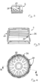
- a safety capsule (also known in the art as a childproof capsule) for a container is indicated by the reference number "1" in the attached figures.
- This safety capsule 1 is utilized to enable the opening and closing of a mouth of a container, but also to prevent accidental access to the contents of the container (for example on the part of a child).
- This capsule 1 is typically applied to the neck of a container. In particular, it is used for pharmaceutical applications.
- This capsule 1 comprises a cap 2 for closing the container.
- the cap 2 comprises a thread 20 for connection to the container. This thread 20 enables the cap 2 to be screwed onto the container so as to enable the closure thereof and to be unscrewed from the container so as to enable extraction of the product contained therein.
- the capsule 1 conveniently comprises a cover 3 for said cap 2.
- the cover 3 comprises a base 30 and a lateral wall 31 that extends from said base 30.
- the cover 3 consists of a single body.
- the base 30 and the lateral wall 31 overlie the cap 2.
- the base 30 is at the opposite end with respect to a zone 4 of the capsule that comprises an intactness band 8 designed to be connected with the container (this intactness band 8 makes the capsule 1 tamper-evident).
- the intactness band 8 is connected to remaining parts of the cap 2 by means of flexible bridges. Prior to breakage, the bridges connect the band 8 to remaining parts of the cap 2.
- the intactness band 8 comprises a strip 29 and a plurality of projections 82, which:
- the cap 2 is preferably made of a plastic material, for example polypropylene or HDPE.
- the cover 3 is preferably made of a plastic material, for example polypropylene or HDPE.
- the capsule 1 comprises a press-fit engagement means 5 that sets said cap 2 and said cover 3 into operative communication, enabling transmission of motion from the cover 3 to the cap 2 for the purpose of making it possible to unscrew said cap 2. If the press-fit engagement means 5 is not activated and a user attempts to unscrew the capsule 1 from the container, the cover 3 turns freely without meshing with the cap 2.
- the press-fit engagement means 5 is at least partly incorporated in said cap 2 and in said cover 3.
- the press-fit engagement means 5 can comprise tabs 34 fashioned as a single piece with the remaining parts of the cover 3 that are inserted in specific seats 25 afforded in the cap 2.
- the tabs 34 are afforded in the base 30 of the cover and they are advantageously arranged radially.
- the capsule 1 further comprises means 6 for preventing extraction of the cover 3 from the cap 2.
- the extraction prevention means 6 performs an action that prevents separation of the cover 3 from the cap 2 following application of a force directed perpendicularly to the base 30.
- This extraction prevention means 6 comprises a first connecting means 61 for connecting the cover 3 to the cap 2 and that extends along a first imaginary annular line.
- the first connecting means 61 is at least partly incorporated in said cap 2 and cover 3.
- the first connecting means 61 comprises a protrusion that interacts with a corresponding abutment, said protrusion and said abutment being afforded one on the cap 2 and the other on the cover 3 (and advantageously being looped annular elements). More specifically, the first connecting means 61 comprises:
- the first abutment 21 is an annular (loop) protrusion that projects towards the cover 3, particularly towards the lateral wall 31 of the cover 3.
- the first connecting ring 610 is inserted under the first abutment 21.
- the first ring 610 extends parallel to a support plane of the container to which the capsule 1 is constrained.
- the first connecting means 61 does not comprise threaded connecting means. More generally, the cover 3 and the cap 2 cannot be separated.
- the cap 2 comprises a flank 26 that faces the lateral wall 31 of the cover 3.
- the flank 26 and the lateral wall 31 are without additional extraction prevention means (with respect to the connecting means 61) that keep the cover connected to the cap (therefore, there are no other means additional to the means 61 that oppose a cap-cover extraction force applied axially along a direction perpendicular to the base 30).
- the cover 3 comprises teeth 7 located in the zone connecting said base 30 and said lateral wall 31.
- the teeth 7 face, and particularly abut, the cap 2.
- the teeth 7 contribute to keeping the cap 2 in position with respect to the cover 3.
- the teeth 7 contribute to keeping the cap 2 coaxial with the cover 3, particularly with the base 30.
- the capsule 1 also comprises means 27 for re-closing the cap on the container after it has been opened and this means is partly incorporated in the cap 2 and partly incorporated in the cover 3.
- the means 27 comprises a first tab 23 projecting towards the lateral wall 31 of the cover 3.
- the first tab 23 is flexible. It is incorporated in the cap 2.
- the first tab 23 surmounts a part of the cap 2, a first concavity 23 being wedged between the first tab 23 and said part of the cap 2 (the first concavity 24 is a recess, an empty space that gives the first tab 23 flexibility).
- the first tab 23 forms an angle of less than 50° with the surface of the cap 2 from which it extends.
- the cap 2 comprises a ridge 91.
- This ridge 91 extends towards the cover 3.
- the ridge 91 serves an important function, given that it counteracts the bending of the second tab 32 as it is being pushed by the first tab 23. In fact, the ridge 91 abuts the upper part of the second tab 32, increasing the stiffness thereof.
- the ridge 91 extends alongside the first tab 23. In particular, the ridge 91 can extend parallel to a zone for connecting the first tab 23 with remaining parts of the cap 2.
- the thickness of the first tab 23 is less than 1 millimetre. It has a tapered shape starting from a zone connecting with remaining parts of the cap 2 and directed towards its own projecting end.
- the means 27 comprises a second tab 32 that projects from the lateral wall 31 of the cover 3 towards the cap 2.
- the second tab 32 is flexible.
- the second tab 32 surmounts one zone of the lateral wall 31 of the cover, a second concavity 33 being wedged between said second tab 32 and said zone of the lateral wall 31 (this second cavity 33 is a recess, an empty space that gives the second tab 32 flexibility).
- this second tab 32 defines an angle of less than 50° with the lateral wall 31 of the cover 3.
- the thickness of the second tab 32 is less than 1 millimetre. It has a tapered shape starting from a zone connecting with remaining parts of the cover 3 and directed towards its own projecting end.
- the first and the second tabs 23, 32 form an angle different from 0 with respect to a radial direction (in other words, they are not oriented radially with respect to an axis oriented perpendicular to said base 30 and passing through the geometric centroid of the capsule 1).
- the inclination of the first and the second tabs 23, 32 allows for a secure connection between the cap 2 and container 3, in spite of the fact that the presence of the first connecting means 61 brings about a reduction in the extension of the first and the second tabs 23, 32 along said axial direction.
- first and the second tabs 23, 32 are located above the first connecting means 61.
- a first direction of rotation of the cover 3 determines the simultaneous insertion of the first tab 23 in the second concavity 33 and the insertion of the second tab 32 in the first concavity 24.
- the first direction of rotation is such as to determine closure of the capsule 1.
- the first direction of rotation enables the transmission of motion from the cover 3 to the cap 2, and the cap 2 to be screwed onto the container.
- a second direction of rotation of the cover 3 determines the sliding of the first tab 23 over the second tab 32 (without insertion in the second concavity; in this case, the upper parts of the first and the second tabs 23, 32 slide one over the other).
- This second direction of rotation is opposite the first direction of rotation.
- the second direction of rotation is the same direction of rotation that determines the unscrewing of the cap 2 from the container in the case in which the press-fit engagement means 5 is activated.
- first and the second tabs 23, 32 extend predominantly along a direction perpendicular to said base 30 of the cover 3.
- the first and the second tabs 23, 32 predominantly extend in a vertical direction with respect to a capsule screwed onto a container that is resting with its support base on a surface.
- the second tab 32 involves more than half of the height of the lateral wall 31 of the cover 3.
- the first tab 23 involves more than half of the height of the cap 2.
- the cap 2 comprises a plurality of convex elements 28 that project towards said lateral wall 31 and that function as lateral cover-cap spacers. These convex elements 28 are distributed circumferentially.
- the cap 2 comprises a plurality of first tabs 23.
- the description provided with reference to the first tab 23 can be repeated for said plurality of first tabs 23.
- the first tabs 23 are flexible, incorporated in the cap 2, project towards the lateral wall 31 of the cover 3 and, with the surface of the cap 2 from which they extend, they form first concavities 24.
- the cover 3 comprises a plurality of second tabs 32.
- the description provided with reference to the second tab 32 can be repeated for said plurality of second tabs 32.
- the second tabs 32 are flexible, project from the lateral wall 31 of the cover 3 towards the cap 2 and, with the lateral wall 31 of the cover 3, they define second concavities 33.
- a first direction of rotation of the cover 3 determines the simultaneous insertion of the first tabs 23 in the corresponding second concavities 33 and the insertion of the second tabs 32 in the corresponding first concavities 24, so as to enable transmission of motion from the cover 3 to the cap 2, and the cap 2 to be screwed onto the container.
- a second direction of rotation of the cover 3 determines the sliding of the first tabs 23 over the second tabs 32.
- the first and the second tabs 23, 32 conveniently define at least three pairs of mutually cooperating tabs.
- said cap 2 is a single monolithic body.
- the band 8, the first tab(s) 23 and a portion of the cap 2 that faces said base 30 are thus part of the monolithic body.
- the object of the present invention is also a method for producing a capsule 1 having one or more of the characteristics described hereinabove.
- the method conveniently comprises the steps of:
- the step of realizing said cap 2 comprises:
- the invention makes it possible to make available a particularly reliable capsule that makes it possible to minimize undesired breakage of the first tabs 23 which could be detrimental to proper functioning of the capsule.
Landscapes
- Engineering & Computer Science (AREA)
- Mechanical Engineering (AREA)
- Closures For Containers (AREA)
Claims (9)
- Capsule de sécurité pour un contenant, comprenant :i) un bouchon (2) pour fermer le contenant, ledit bouchon (2) étant fait d'une matière plastique et comprenant un filetage (20) pour le raccordement au contenant et comprenant également une bande d'intégrité (8) conçue pour être raccordée au contenant ; dans une configuration dans laquelle la bande (8) est intacte, ledit bouchon (2) étant un corps monolithique unique ;ii) un couvercle (3) pour ledit bouchon (2), ledit couvercle (3) comprenant une base (30) et une paroi latérale (31) qui s'étend à partir de ladite base (30) ; ladite base (30) et ladite paroi latérale (31) recouvrant ledit bouchon (2), ladite base (30) étant à l'extrémité opposée par rapport à une zone (4) de la capsule dans laquelle la bande d'intégrité (8) est située ;iii) des moyens de mise en prise inséré à force (5) mettant ledit bouchon (2) et ledit couvercle (3) en communication fonctionnelle, permettant la transmission du mouvement du couvercle (3) au bouchon (2) dans le but de rendre possible le dévissage dudit bouchon (2) ;iv) des moyens (6) pour empêcher l'extraction du couvercle (3) du bouchon (2), comprenant des premiers moyens de raccordement (61) pour raccorder le couvercle (3) au bouchon (2) ; lesdits moyens de mise en prise (5) et lesdits premiers moyens de raccordement (61) étant au moins partiellement incorporés dans lesdits bouchon (2) et couvercle (3) ;v) des moyens pour refermer le bouchon sur le contenant après qu'il a été ouvert, comprenant :- au moins une première languette flexible (23) incorporée dans le bouchon (2) et faisant saillie vers la paroi latérale (31) du couvercle (3) ; ladite première languette (23) surmontant une première partie du bouchon (2), une première concavité (24) étant coincée entre la première languette (23) et ladite première partie du bouchon (2) ;- une deuxième languette flexible (32) faisant saillie de la paroi latérale (31) du couvercle (3) vers le bouchon (2) ; la deuxième languette (32) surmontant une zone de la paroi latérale (31) du couvercle, une deuxième concavité (33) étant coincée entre ladite deuxième languette (32) et ladite zone de la paroi latérale (31) ;un premier sens de rotation du couvercle (3) déterminant l'insertion simultanée de la première languette (23) dans la deuxième concavité (33) et l'insertion de la deuxième languette (32) dans la première concavité (24) de manière à permettre la transmission du mouvement du couvercle (3) au bouchon (2), et le bouchon (2) à visser sur le récipient en conséquence ;une seconde direction de rotation du couvercle (3) déterminant le coulissement des premières languettes (23) sur les secondes languettes (32) ;ladite bande d'intégrité (8) étant raccordée aux parties restantes du bouchon (2) au moyen de ponts flexibles, ladite bande d'intégrité (8) comprenant un ruban (29) et une pluralité de saillies (82) ; ladite pluralité de saillies (82) étant séparées les unes des autres et s'étendant à partir du ruban (29) successivement côte à côte le long d'une ligne circonférentielle ;dans laquelle ladite pluralité de saillies (82) font saillie vers l'intérieur de la capsule (1) et définissent avec le ruban (29) une marche (290) qui identifie un siège (291) pour loger une partie du contenant.
- Capsule selon la revendication 1, caractérisée en ce que ledit bouchon (2) comprend un flanc (26) qui fait face à la paroi latérale (31) du couvercle (3), ledit flanc (26) et ladite paroi latérale (31) étant dépourvus de moyens supplémentaires empêchant l'extraction qui maintiennent le couvercle raccordé au bouchon.
- Capsule selon la revendication 1 ou 2, caractérisée en ce que ledit couvercle (3) est en polypropylène.
- Capsule selon l'une quelconque des revendications précédentes, caractérisée en ce que :- la première languette (23) forme un angle inférieur à 50° avec la surface du bouchon (2) à partir de laquelle elle s'étend, de manière à définir la première concavité (24) ;- la deuxième languette (32) définit un angle inférieur à 50° avec la paroi latérale (31) du couvercle (3), de manière à définir la deuxième concavité (33).
- Capsule selon l'une quelconque des revendications précédentes, caractérisée en ce que l'extension prédominante des première et deuxième languettes (23, 32) est le long d'une direction perpendiculaire à ladite base (30) du couvercle (3) ;
la deuxième languette (32) impliquant plus de la moitié de la hauteur de la paroi latérale (31) du couvercle (3) ; ladite première languette (23) impliquant plus de la moitié de la hauteur du bouchon (2). - Capsule selon l'une quelconque des revendications précédentes, caractérisée en ce que le bouchon (2), à l'ouverture de la première concavité (24), comprend une arête (91) qui s'étend vers le couvercle (3) de manière à contrecarrer une éventuelle flexion de la deuxième languette (32) lorsqu'elle est poussée par la première languette (23).
- Capsule selon l'une quelconque des revendications précédentes, caractérisée en ce que ledit bouchon (2) comprend une pluralité d'éléments convexes (28) qui font saillie vers ladite paroi latérale (31) et qui fonctionnent comme des entretoises latérales de bouchon-couvercle.
- Capsule selon l'une quelconque des revendications précédentes, caractérisée en ce que lesdits premiers moyens de raccordement (61) comprennent :- une première protubérance (611) qui fait saillie de la paroi latérale (31) du couvercle (3) vers ledit capuchon (2), ladite première protubérance (611) comprenant un premier anneau (610) qui est sans soudure ;- une première butée (21) de ladite première protubérance (611), ladite première butée étant incorporée dans le bouchon (2) et interposée entre ladite première protubérance (611) et la base (30).
- Procédé de réalisation d'une capsule selon l'une quelconque des revendications précédentes, caractérisé en ce qu'il comprend :i) réaliser ledit bouchon (2) ;ii) réaliser ledit couvercle (3) ;iii) insérer le bouchon (2) dans le couvercle (3) ;l'étape de réaliser ledit bouchon (2) comprend :- obtenir une pièce brute par moulage ;- faire des coupes à travers ladite pièce brute de manière à réaliser lesdits ponts de raccordement, lesdits ponts étant aptes à se rompre lors de l'ouverture de la capsule (1) ;- plier vers l'intérieur de la capsule (1), une partie du ruban (29) et les saillies (82) faisant saillie à partir dudit ruban (29).
Applications Claiming Priority (2)
| Application Number | Priority Date | Filing Date | Title |
|---|---|---|---|
| ITPR20150023 | 2015-04-10 | ||
| PCT/IB2016/051797 WO2016162777A1 (fr) | 2015-04-10 | 2016-03-30 | Capsule de sécurité pour un contenant |
Publications (2)
| Publication Number | Publication Date |
|---|---|
| EP3280653A1 EP3280653A1 (fr) | 2018-02-14 |
| EP3280653B1 true EP3280653B1 (fr) | 2023-11-29 |
Family
ID=53442871
Family Applications (1)
| Application Number | Title | Priority Date | Filing Date |
|---|---|---|---|
| EP16719137.8A Active EP3280653B1 (fr) | 2015-04-10 | 2016-03-30 | Capsule de sécurité pour un contenant |
Country Status (8)
| Country | Link |
|---|---|
| US (1) | US10457452B2 (fr) |
| EP (1) | EP3280653B1 (fr) |
| CN (1) | CN107548374B (fr) |
| AU (1) | AU2016246120B2 (fr) |
| CA (1) | CA2981209C (fr) |
| ES (1) | ES2970408T3 (fr) |
| SA (1) | SA517390100B1 (fr) |
| WO (1) | WO2016162777A1 (fr) |
Families Citing this family (9)
| Publication number | Priority date | Publication date | Assignee | Title |
|---|---|---|---|---|
| ITUB20153398A1 (it) * | 2015-09-03 | 2017-03-03 | Guala Closures Spa | Contenitore per chiusura riciclabile e assieme contenitore chiusura. |
| CN206603249U (zh) * | 2017-01-23 | 2017-11-03 | 深圳市艾维普思科技股份有限公司 | 压旋式电子烟 |
| US10759554B2 (en) * | 2017-02-02 | 2020-09-01 | Rai Strategic Holdings, Inc. | Dispenser unit for aerosol precursor |
| IT201700046734A1 (it) * | 2017-04-28 | 2018-10-28 | Bormioli Pharma S R L | Capsula di sicurezza con bandella |
| CA3136150A1 (fr) | 2019-04-12 | 2020-10-15 | Ball Corporation | Ensemble de fermeture inviolable a l'epreuve des enfants |
| USD1014251S1 (en) | 2019-06-03 | 2024-02-13 | Berlin Packaging, Llc | Tamper evident closure assembly |
| USD1023755S1 (en) | 2019-06-03 | 2024-04-23 | Berlin Packaging, Llc | Tamper evident closure assembly |
| US11267624B2 (en) * | 2019-11-06 | 2022-03-08 | Silgan White Cap LLC | Two-piece cap |
| US20250242367A1 (en) * | 2022-01-18 | 2025-07-31 | Aptar Radolfzell Gmbh | Liquid dispenser |
Citations (1)
| Publication number | Priority date | Publication date | Assignee | Title |
|---|---|---|---|---|
| EP1953091A1 (fr) * | 2007-01-31 | 2008-08-06 | Obrist Closures Switzerland GmbH | Capuchon de fermeture anti-sabotage, conteneur et combinaison correspondante |
Family Cites Families (16)
| Publication number | Priority date | Publication date | Assignee | Title |
|---|---|---|---|---|
| DE2543453A1 (de) | 1974-10-02 | 1976-04-15 | Ernst Herrmann | Flaschen-sicherheitsverschluss |
| CH580014A5 (fr) * | 1974-10-02 | 1976-09-30 | Herrmann Ernst | |
| US4365722A (en) * | 1981-06-26 | 1982-12-28 | Kramer Steven G | Reminder closure |
| US4598833A (en) * | 1985-08-29 | 1986-07-08 | Kerr Glass Manufacturing Corporation | Tamper-evident child-resistant closure |
| US4832218A (en) * | 1988-07-08 | 1989-05-23 | Merck & Co., Inc. | Child-resistant closure device |
| ATE134581T1 (de) * | 1991-07-30 | 1996-03-15 | Wellcome Found | Behälterverschluss |
| US5188251A (en) * | 1992-05-05 | 1993-02-23 | Owens-Illinois Closure Inc. | Child resistant reminder closure |
| US5316161A (en) * | 1993-04-20 | 1994-05-31 | Comar, Inc. | Child resistant closure |
| CN2207351Y (zh) | 1994-09-30 | 1995-09-13 | 孙小末 | 一种安全瓶盖 |
| US5678712A (en) * | 1995-05-26 | 1997-10-21 | Owens-Illnois Closure Inc. | Child resistant reminder closure |
| CN2388143Y (zh) | 1999-08-04 | 2000-07-19 | 上海海昌医用塑胶厂 | 安全瓶盖 |
| FR2814724B1 (fr) | 2000-10-04 | 2003-04-04 | Airsec Sa | Dispositif de fermeture de securite a l'epreuve d'enfants par vissage d'un conteneur muni d'une embouchure a filet de vis |
| US7815061B1 (en) * | 2006-03-31 | 2010-10-19 | Rexam Closures And Containers | Friction surface for push and turn child resistant closure |
| US20100237072A1 (en) | 2007-10-24 | 2010-09-23 | Jin-Hee Ahn | Closure of vessel |
| US8186526B2 (en) * | 2009-07-08 | 2012-05-29 | Rexam Healthcare Packaging Inc. | Child resistant closure with a stacking position |
| US8857638B2 (en) * | 2010-12-03 | 2014-10-14 | Bprex Healthcare Packaging Inc. | Push-and-turn child-resistant closure, shells, and package |
-
2016
- 2016-03-30 US US15/563,256 patent/US10457452B2/en active Active
- 2016-03-30 ES ES16719137T patent/ES2970408T3/es active Active
- 2016-03-30 AU AU2016246120A patent/AU2016246120B2/en active Active
- 2016-03-30 CA CA2981209A patent/CA2981209C/fr active Active
- 2016-03-30 CN CN201680020299.4A patent/CN107548374B/zh active Active
- 2016-03-30 WO PCT/IB2016/051797 patent/WO2016162777A1/fr not_active Ceased
- 2016-03-30 EP EP16719137.8A patent/EP3280653B1/fr active Active
-
2017
- 2017-10-04 SA SA517390100A patent/SA517390100B1/ar unknown
Patent Citations (1)
| Publication number | Priority date | Publication date | Assignee | Title |
|---|---|---|---|---|
| EP1953091A1 (fr) * | 2007-01-31 | 2008-08-06 | Obrist Closures Switzerland GmbH | Capuchon de fermeture anti-sabotage, conteneur et combinaison correspondante |
Also Published As
| Publication number | Publication date |
|---|---|
| AU2016246120A1 (en) | 2017-10-26 |
| CA2981209A1 (fr) | 2016-10-13 |
| CA2981209C (fr) | 2020-12-22 |
| EP3280653A1 (fr) | 2018-02-14 |
| US20180093802A1 (en) | 2018-04-05 |
| CN107548374B (zh) | 2020-07-17 |
| CN107548374A (zh) | 2018-01-05 |
| ES2970408T3 (es) | 2024-05-28 |
| WO2016162777A1 (fr) | 2016-10-13 |
| AU2016246120B2 (en) | 2019-02-21 |
| US10457452B2 (en) | 2019-10-29 |
| BR112017021786A2 (pt) | 2018-07-10 |
| SA517390100B1 (ar) | 2021-03-31 |
Similar Documents
| Publication | Publication Date | Title |
|---|---|---|
| EP3280653B1 (fr) | Capsule de sécurité pour un contenant | |
| US3955696A (en) | Bottle and safety closure | |
| US20210039840A1 (en) | Closure | |
| US4330067A (en) | Container closure with childproof lock and original package seal | |
| EP3303165B1 (fr) | Fermeture inviolable | |
| US20150014269A1 (en) | Senior friendly child resistant closure | |
| CN113226940A (zh) | 安全盖瓶组件 | |
| US11104494B2 (en) | Non-cocking convertible child resistant closure | |
| US11345527B2 (en) | Safety capsule with strip for preventing extraction | |
| EP2451719B1 (fr) | Fermeture résistant aux enfants avec une position d'empilement | |
| KR102815651B1 (ko) | 합성 수지제 용기 뚜껑 | |
| US10343826B2 (en) | Container lid composed of inside plug and lid body | |
| US10046347B2 (en) | Trigger dispensing device with an unremovable threaded ring-nut | |
| EP3055222B1 (fr) | Capsule de sécurité de contenant | |
| JP6539011B1 (ja) | 合成樹脂製キャップ及び容器 | |
| US20160159533A1 (en) | Child-Resistant Closure | |
| RU2258647C2 (ru) | Предохранительная крышка для бутылок и тому подобного | |
| WO2016026796A1 (fr) | Fermeture à capuchon | |
| JP6180687B1 (ja) | 合成樹脂製キャップ及び容器 | |
| JP2023020386A (ja) | キャップ付き容器 | |
| US3895731A (en) | Closure for receptacles | |
| BR112017021786B1 (pt) | Cápsula de segurança para um recipiente e método para fazer uma cápsula |
Legal Events
| Date | Code | Title | Description |
|---|---|---|---|
| STAA | Information on the status of an ep patent application or granted ep patent |
Free format text: STATUS: THE INTERNATIONAL PUBLICATION HAS BEEN MADE |
|
| PUAI | Public reference made under article 153(3) epc to a published international application that has entered the european phase |
Free format text: ORIGINAL CODE: 0009012 |
|
| STAA | Information on the status of an ep patent application or granted ep patent |
Free format text: STATUS: REQUEST FOR EXAMINATION WAS MADE |
|
| 17P | Request for examination filed |
Effective date: 20170925 |
|
| AK | Designated contracting states |
Kind code of ref document: A1 Designated state(s): AL AT BE BG CH CY CZ DE DK EE ES FI FR GB GR HR HU IE IS IT LI LT LU LV MC MK MT NL NO PL PT RO RS SE SI SK SM TR |
|
| AX | Request for extension of the european patent |
Extension state: BA ME |
|
| RAP1 | Party data changed (applicant data changed or rights of an application transferred) |
Owner name: BORMIOLI PHARMA S.R.L. |
|
| DAV | Request for validation of the european patent (deleted) | ||
| DAX | Request for extension of the european patent (deleted) | ||
| RAP1 | Party data changed (applicant data changed or rights of an application transferred) |
Owner name: BORMIOLI PHARMA S.P.A. |
|
| STAA | Information on the status of an ep patent application or granted ep patent |
Free format text: STATUS: EXAMINATION IS IN PROGRESS |
|
| 17Q | First examination report despatched |
Effective date: 20211108 |
|
| P01 | Opt-out of the competence of the unified patent court (upc) registered |
Effective date: 20230526 |
|
| GRAP | Despatch of communication of intention to grant a patent |
Free format text: ORIGINAL CODE: EPIDOSNIGR1 |
|
| STAA | Information on the status of an ep patent application or granted ep patent |
Free format text: STATUS: GRANT OF PATENT IS INTENDED |
|
| INTG | Intention to grant announced |
Effective date: 20230717 |
|
| GRAS | Grant fee paid |
Free format text: ORIGINAL CODE: EPIDOSNIGR3 |
|
| GRAA | (expected) grant |
Free format text: ORIGINAL CODE: 0009210 |
|
| STAA | Information on the status of an ep patent application or granted ep patent |
Free format text: STATUS: THE PATENT HAS BEEN GRANTED |
|
| AK | Designated contracting states |
Kind code of ref document: B1 Designated state(s): AL AT BE BG CH CY CZ DE DK EE ES FI FR GB GR HR HU IE IS IT LI LT LU LV MC MK MT NL NO PL PT RO RS SE SI SK SM TR |
|
| REG | Reference to a national code |
Ref country code: GB Ref legal event code: FG4D |
|
| REG | Reference to a national code |
Ref country code: CH Ref legal event code: EP |
|
| REG | Reference to a national code |
Ref country code: DE Ref legal event code: R096 Ref document number: 602016084375 Country of ref document: DE |
|
| REG | Reference to a national code |
Ref country code: IE Ref legal event code: FG4D |
|
| REG | Reference to a national code |
Ref country code: LT Ref legal event code: MG9D |
|
| REG | Reference to a national code |
Ref country code: NL Ref legal event code: MP Effective date: 20231129 |
|
| PG25 | Lapsed in a contracting state [announced via postgrant information from national office to epo] |
Ref country code: GR Free format text: LAPSE BECAUSE OF FAILURE TO SUBMIT A TRANSLATION OF THE DESCRIPTION OR TO PAY THE FEE WITHIN THE PRESCRIBED TIME-LIMIT Effective date: 20240301 |
|
| PG25 | Lapsed in a contracting state [announced via postgrant information from national office to epo] |
Ref country code: IS Free format text: LAPSE BECAUSE OF FAILURE TO SUBMIT A TRANSLATION OF THE DESCRIPTION OR TO PAY THE FEE WITHIN THE PRESCRIBED TIME-LIMIT Effective date: 20240329 |
|
| PG25 | Lapsed in a contracting state [announced via postgrant information from national office to epo] |
Ref country code: LT Free format text: LAPSE BECAUSE OF FAILURE TO SUBMIT A TRANSLATION OF THE DESCRIPTION OR TO PAY THE FEE WITHIN THE PRESCRIBED TIME-LIMIT Effective date: 20231129 |
|
| PG25 | Lapsed in a contracting state [announced via postgrant information from national office to epo] |
Ref country code: LT Free format text: LAPSE BECAUSE OF FAILURE TO SUBMIT A TRANSLATION OF THE DESCRIPTION OR TO PAY THE FEE WITHIN THE PRESCRIBED TIME-LIMIT Effective date: 20231129 Ref country code: IS Free format text: LAPSE BECAUSE OF FAILURE TO SUBMIT A TRANSLATION OF THE DESCRIPTION OR TO PAY THE FEE WITHIN THE PRESCRIBED TIME-LIMIT Effective date: 20240329 Ref country code: GR Free format text: LAPSE BECAUSE OF FAILURE TO SUBMIT A TRANSLATION OF THE DESCRIPTION OR TO PAY THE FEE WITHIN THE PRESCRIBED TIME-LIMIT Effective date: 20240301 Ref country code: BG Free format text: LAPSE BECAUSE OF FAILURE TO SUBMIT A TRANSLATION OF THE DESCRIPTION OR TO PAY THE FEE WITHIN THE PRESCRIBED TIME-LIMIT Effective date: 20240229 |
|
| PG25 | Lapsed in a contracting state [announced via postgrant information from national office to epo] |
Ref country code: NL Free format text: LAPSE BECAUSE OF FAILURE TO SUBMIT A TRANSLATION OF THE DESCRIPTION OR TO PAY THE FEE WITHIN THE PRESCRIBED TIME-LIMIT Effective date: 20231129 |
|
| REG | Reference to a national code |
Ref country code: ES Ref legal event code: FG2A Ref document number: 2970408 Country of ref document: ES Kind code of ref document: T3 Effective date: 20240528 |
|
| PG25 | Lapsed in a contracting state [announced via postgrant information from national office to epo] |
Ref country code: SE Free format text: LAPSE BECAUSE OF FAILURE TO SUBMIT A TRANSLATION OF THE DESCRIPTION OR TO PAY THE FEE WITHIN THE PRESCRIBED TIME-LIMIT Effective date: 20231129 Ref country code: RS Free format text: LAPSE BECAUSE OF FAILURE TO SUBMIT A TRANSLATION OF THE DESCRIPTION OR TO PAY THE FEE WITHIN THE PRESCRIBED TIME-LIMIT Effective date: 20231129 Ref country code: PL Free format text: LAPSE BECAUSE OF FAILURE TO SUBMIT A TRANSLATION OF THE DESCRIPTION OR TO PAY THE FEE WITHIN THE PRESCRIBED TIME-LIMIT Effective date: 20231129 Ref country code: NO Free format text: LAPSE BECAUSE OF FAILURE TO SUBMIT A TRANSLATION OF THE DESCRIPTION OR TO PAY THE FEE WITHIN THE PRESCRIBED TIME-LIMIT Effective date: 20240229 Ref country code: NL Free format text: LAPSE BECAUSE OF FAILURE TO SUBMIT A TRANSLATION OF THE DESCRIPTION OR TO PAY THE FEE WITHIN THE PRESCRIBED TIME-LIMIT Effective date: 20231129 Ref country code: LV Free format text: LAPSE BECAUSE OF FAILURE TO SUBMIT A TRANSLATION OF THE DESCRIPTION OR TO PAY THE FEE WITHIN THE PRESCRIBED TIME-LIMIT Effective date: 20231129 Ref country code: HR Free format text: LAPSE BECAUSE OF FAILURE TO SUBMIT A TRANSLATION OF THE DESCRIPTION OR TO PAY THE FEE WITHIN THE PRESCRIBED TIME-LIMIT Effective date: 20231129 |
|
| REG | Reference to a national code |
Ref country code: AT Ref legal event code: UEP Ref document number: 1635911 Country of ref document: AT Kind code of ref document: T Effective date: 20231129 |
|
| PG25 | Lapsed in a contracting state [announced via postgrant information from national office to epo] |
Ref country code: DK Free format text: LAPSE BECAUSE OF FAILURE TO SUBMIT A TRANSLATION OF THE DESCRIPTION OR TO PAY THE FEE WITHIN THE PRESCRIBED TIME-LIMIT Effective date: 20231129 |
|
| PG25 | Lapsed in a contracting state [announced via postgrant information from national office to epo] |
Ref country code: CZ Free format text: LAPSE BECAUSE OF FAILURE TO SUBMIT A TRANSLATION OF THE DESCRIPTION OR TO PAY THE FEE WITHIN THE PRESCRIBED TIME-LIMIT Effective date: 20231129 |
|
| PG25 | Lapsed in a contracting state [announced via postgrant information from national office to epo] |
Ref country code: SK Free format text: LAPSE BECAUSE OF FAILURE TO SUBMIT A TRANSLATION OF THE DESCRIPTION OR TO PAY THE FEE WITHIN THE PRESCRIBED TIME-LIMIT Effective date: 20231129 |
|
| PG25 | Lapsed in a contracting state [announced via postgrant information from national office to epo] |
Ref country code: SM Free format text: LAPSE BECAUSE OF FAILURE TO SUBMIT A TRANSLATION OF THE DESCRIPTION OR TO PAY THE FEE WITHIN THE PRESCRIBED TIME-LIMIT Effective date: 20231129 Ref country code: SK Free format text: LAPSE BECAUSE OF FAILURE TO SUBMIT A TRANSLATION OF THE DESCRIPTION OR TO PAY THE FEE WITHIN THE PRESCRIBED TIME-LIMIT Effective date: 20231129 Ref country code: RO Free format text: LAPSE BECAUSE OF FAILURE TO SUBMIT A TRANSLATION OF THE DESCRIPTION OR TO PAY THE FEE WITHIN THE PRESCRIBED TIME-LIMIT Effective date: 20231129 Ref country code: EE Free format text: LAPSE BECAUSE OF FAILURE TO SUBMIT A TRANSLATION OF THE DESCRIPTION OR TO PAY THE FEE WITHIN THE PRESCRIBED TIME-LIMIT Effective date: 20231129 Ref country code: DK Free format text: LAPSE BECAUSE OF FAILURE TO SUBMIT A TRANSLATION OF THE DESCRIPTION OR TO PAY THE FEE WITHIN THE PRESCRIBED TIME-LIMIT Effective date: 20231129 Ref country code: CZ Free format text: LAPSE BECAUSE OF FAILURE TO SUBMIT A TRANSLATION OF THE DESCRIPTION OR TO PAY THE FEE WITHIN THE PRESCRIBED TIME-LIMIT Effective date: 20231129 |
|
| PG25 | Lapsed in a contracting state [announced via postgrant information from national office to epo] |
Ref country code: PT Free format text: LAPSE BECAUSE OF FAILURE TO SUBMIT A TRANSLATION OF THE DESCRIPTION OR TO PAY THE FEE WITHIN THE PRESCRIBED TIME-LIMIT Effective date: 20240401 |
|
| PG25 | Lapsed in a contracting state [announced via postgrant information from national office to epo] |
Ref country code: PT Free format text: LAPSE BECAUSE OF FAILURE TO SUBMIT A TRANSLATION OF THE DESCRIPTION OR TO PAY THE FEE WITHIN THE PRESCRIBED TIME-LIMIT Effective date: 20240401 |
|
| REG | Reference to a national code |
Ref country code: DE Ref legal event code: R097 Ref document number: 602016084375 Country of ref document: DE |
|
| PLBE | No opposition filed within time limit |
Free format text: ORIGINAL CODE: 0009261 |
|
| STAA | Information on the status of an ep patent application or granted ep patent |
Free format text: STATUS: NO OPPOSITION FILED WITHIN TIME LIMIT |
|
| PG25 | Lapsed in a contracting state [announced via postgrant information from national office to epo] |
Ref country code: SI Free format text: LAPSE BECAUSE OF FAILURE TO SUBMIT A TRANSLATION OF THE DESCRIPTION OR TO PAY THE FEE WITHIN THE PRESCRIBED TIME-LIMIT Effective date: 20231129 |
|
| PG25 | Lapsed in a contracting state [announced via postgrant information from national office to epo] |
Ref country code: SI Free format text: LAPSE BECAUSE OF FAILURE TO SUBMIT A TRANSLATION OF THE DESCRIPTION OR TO PAY THE FEE WITHIN THE PRESCRIBED TIME-LIMIT Effective date: 20231129 |
|
| 26N | No opposition filed |
Effective date: 20240830 |
|
| PG25 | Lapsed in a contracting state [announced via postgrant information from national office to epo] |
Ref country code: LU Free format text: LAPSE BECAUSE OF NON-PAYMENT OF DUE FEES Effective date: 20240330 |
|
| PG25 | Lapsed in a contracting state [announced via postgrant information from national office to epo] |
Ref country code: MC Free format text: LAPSE BECAUSE OF FAILURE TO SUBMIT A TRANSLATION OF THE DESCRIPTION OR TO PAY THE FEE WITHIN THE PRESCRIBED TIME-LIMIT Effective date: 20231129 |
|
| PG25 | Lapsed in a contracting state [announced via postgrant information from national office to epo] |
Ref country code: MC Free format text: LAPSE BECAUSE OF FAILURE TO SUBMIT A TRANSLATION OF THE DESCRIPTION OR TO PAY THE FEE WITHIN THE PRESCRIBED TIME-LIMIT Effective date: 20231129 Ref country code: LU Free format text: LAPSE BECAUSE OF NON-PAYMENT OF DUE FEES Effective date: 20240330 |
|
| PG25 | Lapsed in a contracting state [announced via postgrant information from national office to epo] |
Ref country code: IE Free format text: LAPSE BECAUSE OF NON-PAYMENT OF DUE FEES Effective date: 20240330 |
|
| PG25 | Lapsed in a contracting state [announced via postgrant information from national office to epo] |
Ref country code: IE Free format text: LAPSE BECAUSE OF NON-PAYMENT OF DUE FEES Effective date: 20240330 |
|
| PGFP | Annual fee paid to national office [announced via postgrant information from national office to epo] |
Ref country code: ES Payment date: 20250417 Year of fee payment: 10 |
|
| PGFP | Annual fee paid to national office [announced via postgrant information from national office to epo] |
Ref country code: IT Payment date: 20250327 Year of fee payment: 10 |
|
| PGFP | Annual fee paid to national office [announced via postgrant information from national office to epo] |
Ref country code: CH Payment date: 20250401 Year of fee payment: 10 |
|
| PG25 | Lapsed in a contracting state [announced via postgrant information from national office to epo] |
Ref country code: CY Free format text: LAPSE BECAUSE OF FAILURE TO SUBMIT A TRANSLATION OF THE DESCRIPTION OR TO PAY THE FEE WITHIN THE PRESCRIBED TIME-LIMIT; INVALID AB INITIO Effective date: 20160330 |
|
| PG25 | Lapsed in a contracting state [announced via postgrant information from national office to epo] |
Ref country code: HU Free format text: LAPSE BECAUSE OF FAILURE TO SUBMIT A TRANSLATION OF THE DESCRIPTION OR TO PAY THE FEE WITHIN THE PRESCRIBED TIME-LIMIT; INVALID AB INITIO Effective date: 20160330 |
|
| PG25 | Lapsed in a contracting state [announced via postgrant information from national office to epo] |
Ref country code: FI Free format text: LAPSE BECAUSE OF FAILURE TO SUBMIT A TRANSLATION OF THE DESCRIPTION OR TO PAY THE FEE WITHIN THE PRESCRIBED TIME-LIMIT Effective date: 20231129 |
|
| PG25 | Lapsed in a contracting state [announced via postgrant information from national office to epo] |
Ref country code: TR Free format text: LAPSE BECAUSE OF FAILURE TO SUBMIT A TRANSLATION OF THE DESCRIPTION OR TO PAY THE FEE WITHIN THE PRESCRIBED TIME-LIMIT Effective date: 20231129 |
|
| REG | Reference to a national code |
Ref country code: CH Ref legal event code: U11 Free format text: ST27 STATUS EVENT CODE: U-0-0-U10-U11 (AS PROVIDED BY THE NATIONAL OFFICE) Effective date: 20260401 |
|
| PGFP | Annual fee paid to national office [announced via postgrant information from national office to epo] |
Ref country code: GB Payment date: 20260324 Year of fee payment: 11 |
|
| PGFP | Annual fee paid to national office [announced via postgrant information from national office to epo] |
Ref country code: DE Payment date: 20260320 Year of fee payment: 11 |
|
| PGFP | Annual fee paid to national office [announced via postgrant information from national office to epo] |
Ref country code: AT Payment date: 20260319 Year of fee payment: 11 |
|
| PGFP | Annual fee paid to national office [announced via postgrant information from national office to epo] |
Ref country code: BE Payment date: 20260323 Year of fee payment: 11 |
|
| PGFP | Annual fee paid to national office [announced via postgrant information from national office to epo] |
Ref country code: FR Payment date: 20260325 Year of fee payment: 11 |