EP3280687B1 - Fibre optique monomode à faible atténuation dotée d'une couche de relâchement des contraintes, sa préforme et un procédé pour sa fabrication - Google Patents
Fibre optique monomode à faible atténuation dotée d'une couche de relâchement des contraintes, sa préforme et un procédé pour sa fabrication Download PDFInfo
- Publication number
- EP3280687B1 EP3280687B1 EP16717757.5A EP16717757A EP3280687B1 EP 3280687 B1 EP3280687 B1 EP 3280687B1 EP 16717757 A EP16717757 A EP 16717757A EP 3280687 B1 EP3280687 B1 EP 3280687B1
- Authority
- EP
- European Patent Office
- Prior art keywords
- outer cladding
- optical fiber
- core
- preform
- equal
- Prior art date
- Legal status (The legal status is an assumption and is not a legal conclusion. Google has not performed a legal analysis and makes no representation as to the accuracy of the status listed.)
- Active
Links
Images


Classifications
-
- G—PHYSICS
- G02—OPTICS
- G02B—OPTICAL ELEMENTS, SYSTEMS OR APPARATUS
- G02B6/00—Light guides; Structural details of arrangements comprising light guides and other optical elements, e.g. couplings
- G02B6/02—Optical fibres with cladding with or without a coating
- G02B6/036—Optical fibres with cladding with or without a coating core or cladding comprising multiple layers
- G02B6/03694—Multiple layers differing in properties other than the refractive index, e.g. attenuation, diffusion, stress properties
-
- C—CHEMISTRY; METALLURGY
- C03—GLASS; MINERAL OR SLAG WOOL
- C03B—MANUFACTURE, SHAPING, OR SUPPLEMENTARY PROCESSES
- C03B37/00—Manufacture or treatment of flakes, fibres, or filaments from softened glass, minerals, or slags
- C03B37/01—Manufacture of glass fibres or filaments
- C03B37/02—Manufacture of glass fibres or filaments by drawing or extruding, e.g. direct drawing of molten glass from nozzles; Cooling fins therefor
- C03B37/025—Manufacture of glass fibres or filaments by drawing or extruding, e.g. direct drawing of molten glass from nozzles; Cooling fins therefor from reheated softened tubes, rods, fibres or filaments, e.g. drawing fibres from preforms
- C03B37/027—Fibres composed of different sorts of glass, e.g. glass optical fibres
-
- C—CHEMISTRY; METALLURGY
- C03—GLASS; MINERAL OR SLAG WOOL
- C03C—CHEMICAL COMPOSITION OF GLASSES, GLAZES OR VITREOUS ENAMELS; SURFACE TREATMENT OF GLASS; SURFACE TREATMENT OF FIBRES OR FILAMENTS MADE FROM GLASS, MINERALS OR SLAGS; JOINING GLASS TO GLASS OR OTHER MATERIALS
- C03C3/00—Glass compositions
- C03C3/04—Glass compositions containing silica
- C03C3/06—Glass compositions containing silica with more than 90% silica by weight, e.g. quartz
-
- G—PHYSICS
- G02—OPTICS
- G02B—OPTICAL ELEMENTS, SYSTEMS OR APPARATUS
- G02B6/00—Light guides; Structural details of arrangements comprising light guides and other optical elements, e.g. couplings
- G02B6/02—Optical fibres with cladding with or without a coating
- G02B6/02395—Glass optical fibre with a protective coating, e.g. two layer polymer coating deposited directly on a silica cladding surface during fibre manufacture
-
- G—PHYSICS
- G02—OPTICS
- G02B—OPTICAL ELEMENTS, SYSTEMS OR APPARATUS
- G02B6/00—Light guides; Structural details of arrangements comprising light guides and other optical elements, e.g. couplings
- G02B6/02—Optical fibres with cladding with or without a coating
- G02B6/036—Optical fibres with cladding with or without a coating core or cladding comprising multiple layers
- G02B6/03616—Optical fibres characterised both by the number of different refractive index layers around the central core segment, i.e. around the innermost high index core layer, and their relative refractive index difference
- G02B6/03638—Optical fibres characterised both by the number of different refractive index layers around the central core segment, i.e. around the innermost high index core layer, and their relative refractive index difference having 3 layers only
- G02B6/03644—Optical fibres characterised both by the number of different refractive index layers around the central core segment, i.e. around the innermost high index core layer, and their relative refractive index difference having 3 layers only arranged - + -
-
- C—CHEMISTRY; METALLURGY
- C03—GLASS; MINERAL OR SLAG WOOL
- C03B—MANUFACTURE, SHAPING, OR SUPPLEMENTARY PROCESSES
- C03B2201/00—Type of glass produced
- C03B2201/06—Doped silica-based glasses
- C03B2201/20—Doped silica-based glasses doped with non-metals other than boron or fluorine
-
- C—CHEMISTRY; METALLURGY
- C03—GLASS; MINERAL OR SLAG WOOL
- C03B—MANUFACTURE, SHAPING, OR SUPPLEMENTARY PROCESSES
- C03B2201/00—Type of glass produced
- C03B2201/06—Doped silica-based glasses
- C03B2201/20—Doped silica-based glasses doped with non-metals other than boron or fluorine
- C03B2201/24—Doped silica-based glasses doped with non-metals other than boron or fluorine doped with nitrogen, e.g. silicon oxy-nitride glasses
-
- C—CHEMISTRY; METALLURGY
- C03—GLASS; MINERAL OR SLAG WOOL
- C03B—MANUFACTURE, SHAPING, OR SUPPLEMENTARY PROCESSES
- C03B2201/00—Type of glass produced
- C03B2201/06—Doped silica-based glasses
- C03B2201/30—Doped silica-based glasses doped with metals, e.g. Ga, Sn, Sb, Pb or Bi
- C03B2201/31—Doped silica-based glasses doped with metals, e.g. Ga, Sn, Sb, Pb or Bi doped with germanium
-
- C—CHEMISTRY; METALLURGY
- C03—GLASS; MINERAL OR SLAG WOOL
- C03B—MANUFACTURE, SHAPING, OR SUPPLEMENTARY PROCESSES
- C03B2203/00—Fibre product details, e.g. structure, shape
- C03B2203/10—Internal structure or shape details
- C03B2203/22—Radial profile of refractive index, composition or softening point
- C03B2203/222—Mismatching viscosities or softening points of glass layers
-
- C—CHEMISTRY; METALLURGY
- C03—GLASS; MINERAL OR SLAG WOOL
- C03B—MANUFACTURE, SHAPING, OR SUPPLEMENTARY PROCESSES
- C03B2203/00—Fibre product details, e.g. structure, shape
- C03B2203/10—Internal structure or shape details
- C03B2203/22—Radial profile of refractive index, composition or softening point
- C03B2203/23—Double or multiple optical cladding profiles
-
- C—CHEMISTRY; METALLURGY
- C03—GLASS; MINERAL OR SLAG WOOL
- C03B—MANUFACTURE, SHAPING, OR SUPPLEMENTARY PROCESSES
- C03B2203/00—Fibre product details, e.g. structure, shape
- C03B2203/10—Internal structure or shape details
- C03B2203/22—Radial profile of refractive index, composition or softening point
- C03B2203/24—Single mode [SM or monomode]
-
- C—CHEMISTRY; METALLURGY
- C03—GLASS; MINERAL OR SLAG WOOL
- C03B—MANUFACTURE, SHAPING, OR SUPPLEMENTARY PROCESSES
- C03B37/00—Manufacture or treatment of flakes, fibres, or filaments from softened glass, minerals, or slags
- C03B37/01—Manufacture of glass fibres or filaments
- C03B37/012—Manufacture of preforms for drawing fibres or filaments
- C03B37/014—Manufacture of preforms for drawing fibres or filaments made entirely or partially by chemical means, e.g. vapour phase deposition of bulk porous glass either by outside vapour deposition [OVD], or by outside vapour phase oxidation [OVPO] or by vapour axial deposition [VAD]
- C03B37/018—Manufacture of preforms for drawing fibres or filaments made entirely or partially by chemical means, e.g. vapour phase deposition of bulk porous glass either by outside vapour deposition [OVD], or by outside vapour phase oxidation [OVPO] or by vapour axial deposition [VAD] by glass deposition on a glass substrate, e.g. by inside-, modified-, plasma- or plasma modified- chemical vapour deposition [ICVD, MCVD, PCVD, PMCVD], i.e. by thin layer coating on the inside or outside of a glass tube or on a glass rod
-
- C—CHEMISTRY; METALLURGY
- C03—GLASS; MINERAL OR SLAG WOOL
- C03C—CHEMICAL COMPOSITION OF GLASSES, GLAZES OR VITREOUS ENAMELS; SURFACE TREATMENT OF GLASS; SURFACE TREATMENT OF FIBRES OR FILAMENTS MADE FROM GLASS, MINERALS OR SLAGS; JOINING GLASS TO GLASS OR OTHER MATERIALS
- C03C13/00—Fibre or filament compositions
- C03C13/04—Fibre optics, e.g. core and clad fibre compositions
- C03C13/045—Silica-containing oxide glass compositions
-
- C—CHEMISTRY; METALLURGY
- C03—GLASS; MINERAL OR SLAG WOOL
- C03C—CHEMICAL COMPOSITION OF GLASSES, GLAZES OR VITREOUS ENAMELS; SURFACE TREATMENT OF GLASS; SURFACE TREATMENT OF FIBRES OR FILAMENTS MADE FROM GLASS, MINERALS OR SLAGS; JOINING GLASS TO GLASS OR OTHER MATERIALS
- C03C2201/00—Glass compositions
- C03C2201/06—Doped silica-based glasses
- C03C2201/08—Doped silica-based glasses containing boron or halide
- C03C2201/11—Doped silica-based glasses containing boron or halide containing chlorine
-
- C—CHEMISTRY; METALLURGY
- C03—GLASS; MINERAL OR SLAG WOOL
- C03C—CHEMICAL COMPOSITION OF GLASSES, GLAZES OR VITREOUS ENAMELS; SURFACE TREATMENT OF GLASS; SURFACE TREATMENT OF FIBRES OR FILAMENTS MADE FROM GLASS, MINERALS OR SLAGS; JOINING GLASS TO GLASS OR OTHER MATERIALS
- C03C2201/00—Glass compositions
- C03C2201/06—Doped silica-based glasses
- C03C2201/20—Doped silica-based glasses containing non-metals other than boron or halide
- C03C2201/24—Doped silica-based glasses containing non-metals other than boron or halide containing nitrogen, e.g. silicon oxy-nitride glasses
-
- C—CHEMISTRY; METALLURGY
- C03—GLASS; MINERAL OR SLAG WOOL
- C03C—CHEMICAL COMPOSITION OF GLASSES, GLAZES OR VITREOUS ENAMELS; SURFACE TREATMENT OF GLASS; SURFACE TREATMENT OF FIBRES OR FILAMENTS MADE FROM GLASS, MINERALS OR SLAGS; JOINING GLASS TO GLASS OR OTHER MATERIALS
- C03C2201/00—Glass compositions
- C03C2201/06—Doped silica-based glasses
- C03C2201/30—Doped silica-based glasses containing metals
- C03C2201/31—Doped silica-based glasses containing metals containing germanium
-
- C—CHEMISTRY; METALLURGY
- C03—GLASS; MINERAL OR SLAG WOOL
- C03C—CHEMICAL COMPOSITION OF GLASSES, GLAZES OR VITREOUS ENAMELS; SURFACE TREATMENT OF GLASS; SURFACE TREATMENT OF FIBRES OR FILAMENTS MADE FROM GLASS, MINERALS OR SLAGS; JOINING GLASS TO GLASS OR OTHER MATERIALS
- C03C3/00—Glass compositions
- C03C3/04—Glass compositions containing silica
- C03C3/076—Glass compositions containing silica with 40% to 90% silica, by weight
-
- G—PHYSICS
- G02—OPTICS
- G02B—OPTICAL ELEMENTS, SYSTEMS OR APPARATUS
- G02B6/00—Light guides; Structural details of arrangements comprising light guides and other optical elements, e.g. couplings
- G02B6/02—Optical fibres with cladding with or without a coating
- G02B6/028—Optical fibres with cladding with or without a coating with core or cladding having graded refractive index
- G02B6/0281—Graded index region forming part of the central core segment, e.g. alpha profile, triangular, trapezoidal core
-
- G—PHYSICS
- G02—OPTICS
- G02B—OPTICAL ELEMENTS, SYSTEMS OR APPARATUS
- G02B6/00—Light guides; Structural details of arrangements comprising light guides and other optical elements, e.g. couplings
- G02B6/02—Optical fibres with cladding with or without a coating
- G02B6/036—Optical fibres with cladding with or without a coating core or cladding comprising multiple layers
- G02B6/03616—Optical fibres characterised both by the number of different refractive index layers around the central core segment, i.e. around the innermost high index core layer, and their relative refractive index difference
- G02B6/03622—Optical fibres characterised both by the number of different refractive index layers around the central core segment, i.e. around the innermost high index core layer, and their relative refractive index difference having 2 layers only
- G02B6/03627—Optical fibres characterised both by the number of different refractive index layers around the central core segment, i.e. around the innermost high index core layer, and their relative refractive index difference having 2 layers only arranged - +
Definitions
- the present disclosure relates generally to optical fibers, and particularly to low attenuation optical fibers.
- Glass optical fibers with low attenuation have recently been of significant interest in the telecommunications field.
- Techniques for improving attenuation properties can play important roles in many types of fibers, including transmission fibers used in long distance applications, multimode fibers used in the emerging area of fiber to the home applications, and dispersion compensation fibers where bending loss has limited many designs from practical use.
- low attenuation is desired to deliver data accurately via light signals.
- Many of the proposed solutions for this problem involve significant modification of the fiber and its refractive index profile.
- US 2011/058780 discloses a single mode optical fiber comprising a silica core doped with germania and fluorine.
- WO 2012/084050 discloses a low macro-bending loss single mode optical fiber with a central core region made of silica doped with germanium.
- a single mode optical fiber according to claim 1.
- the viscosity at 1650°C of the second outer cladding portion minus the viscosity at 1650°C of the first outer cladding portion is ⁇ 5 x 10 6 Poise.
- the viscosity at 1650°C of the second outer cladding portion minus the viscosity at 1650°C of the first outer cladding portion is ⁇ 0.1e 7 Poise and ⁇ 1.6e 8 Poise.
- the difference between the glass softening point of the second outer cladding portion and the glass softening point of the first outer cladding portion is greater than or equal to 2°C. In some embodiments the difference between the glass softening point of the second outer cladding portion and the glass softening point of the first outer cladding portion is greater than or equal to 3°C. (e.g., 3 °C to 100°C, for example 3 °C to 25°C). In some embodiments the difference between the glass softening point of the second outer cladding portion and the glass softening point of the first outer cladding portion is greater than or equal to 7°C, e.g., 7 to 100°C.
- the difference between the glass softening point of the second outer cladding portion and the glass softening point of the first outer cladding portion is 7°C, e.g., 7 to 20°C.
- the second portion of the outer cladding is made from silica or SiON.
- the first outer cladding portion has a maximum relative refractive index ⁇ 3MAX , and ⁇ 3MAX > ⁇ 2
- the first outer cladding portion comprises chlorine doped silica, and has a relative refractive index ⁇ 3A , and ⁇ 3A > ⁇ 2 .
- the core has an outer radius of 3 microns to 10 microns, and the inner cladding has a radial thickness that is at least 5 microns.
- the first outer cladding portion comprises chlorine doped silica and has a relative refractive index ⁇ 3A
- the second outer cladding portion comprises chlorine doped silica, silica or SiON.
- the second outer cladding portion comprises less chlorine than the first outer cladding portion.
- a method of drawing an optical fiber is provided according to claim 14.
- FIG. 1A schematically depicts a cross section of an optical fiber 100 according to one or more embodiments shown and described herein.
- Embodiments of optical fibers 100 described herein generally comprise a single mode optical fiber having a core 102 made from silica (SiO 2 ) and germania (GeO 2 ), with less than or equal to about 11 weight % germania.
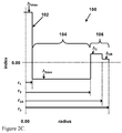
- FIGs. 2A-2C graphically depict exemplary index profiles versus radius of several embodiments of the optical fiber 100 depicted in FIG. 1A .
- the fiber core 102 also referred to herein as core layer and core portion
- the optical fiber 100 also has an inner cladding 104 (also referred to herein as an inner cladding layer) surrounding the core 102 that has a relative refractive index ⁇ 2 , and ⁇ 1MAX > ⁇ 2 .
- An outer cladding 106 surrounds the inner cladding 104.
- the outer cladding 106 (also referred to herein as outer clad) comprises two portions, a first outer cladding portion 106A (also referred to herein as first outer cladding layer) and a second outer cladding portion 106B (also referred to herein as second outer cladding layer or the second outer clad layer).
- the portion 106A of the outer cladding 106 is directly adjacent to the inner cladding 104 and has a relative refractive index ⁇ 3A where ⁇ 1MAX > ⁇ 3A > ⁇ 2 .
- the portion 106B of the outer cladding 106 surrounds the outer cladding portion 106A and is directly adjacent to the first outer cladding portion 106A.
- the second outer cladding portion 106B has an average relative refractive index ⁇ 3B , and ⁇ 3A > ⁇ 3B .
- ( ⁇ 3A - ⁇ 3B ) ⁇ 0.02%.
- ( ⁇ 3A - ⁇ 3B ) ⁇ 0.08%.
- ( ⁇ 3A - ⁇ 3B ) ⁇ 0.14%. According to some embodiments, 0.2% ⁇ ( ⁇ 3A - ⁇ 3B ) ⁇ 0.02%. According to some embodiments, 02% ⁇ ( ⁇ 3A - ⁇ 3B ) ⁇ 0.05%. According to some other embodiments, 0.14% ⁇ ( ⁇ 3A - ⁇ 3B ) ⁇ 0.05%. According to some other embodiments, 0.14% ⁇ ( ⁇ 3A - ⁇ 3B ) ⁇ 0.08%.
- the relative refractive index of inner cladding 104 is equal to the average relative index of second outer cladding layer (second outer cladding portion) 106B, and both layers 104 and 106B are comprised essentially of silica.
- composition of the glass layers ( 106A, 106B ) determines the refractive index (index delta) of each layer.
- the outer most portion (or the second outer cladding portion 106B ) of the cladding 106 is a stress relieving layer, and 1) reduces tensile stress placed on the inner cladding 104 and on the core 102, which results in lower fiber attenuation, while 2) enabling the fiber to have excellent bend performance (low macro-bend loss).
- the second outer cladding portion 106B of the cladding 106 has a higher softening point than the softening point of the first outer cladding portion 106A of the cladding 106.
- the softening point of the second outer cladding portion 106B of the cladding 106 is higher than the softening point of the first outer cladding portion 106A of the cladding 106.
- the difference between the glass softening point of the second outer cladding portion 106B and the glass softening point of the first outer cladding portion 106A is greater than or equal to about 3°C (i.e., T S106B -T S106A ⁇ 3°C (for example, in some embodiments 100°C >T S106B -T S106A ⁇ 3°C)).
- the softening points of these two layers 106A and 106B relate to the glass viscosity of these layers.
- the softening point of the outer cladding portions 106A and 106B is the temperature T soft where the glass composition has a viscosity of 10 7.6 Poise.
- FIG. 2D A typical profile of a long haul transmission commercial fiber is shown in Fig. 2D (comparative fiber example).
- This comparative example fiber comprises a germania (GeO 2 ) doped core, surrounded by an inner cladding layer that is comprised essentially of pure silica, and a silica based single layer outer cladding that is uniformly updoped to increase the refractive index of the outer cladding relative to the inner cladding.
- the updoped outer cladding in such a commercial optical fiber is typically achieved by doping the outer cladding with updopants such as chlorine (using dopant precursors such as chlorine, SiCl 4 , etc.), germania, or alumina.
- the dopants used in the outer cladding layer of commercial optical fibers result in lowering the viscosity of the outer cladding layer compared to that of the inner cladding layer, making the stiff inner cladding carry the maximum stress induced during drawing of such comparative optical fibers.
- the increased tensile load in the inner cladding of such commercial fibers results in a negative impact on the structural relaxation the glass undergoes during the fiber draw, and thereby increases the resultant optical fiber attenuation.
- the outer cladding 106 with a stiff stress relieving layer (second outer cladding portion 106B ) as the outermost portion of the outer cladding 106 of the optical fiber 100.
- the first outer cladding portion 106A has a lower viscosity than that of the inner cladding 104, but the second outer cladding portion 106B (the stress relieving layer) has a higher viscosity than that of the first outer cladding portion 106A.
- the viscosity of second outer cladding portion 106B is also equal or higher than the viscosity of the inner cladding 104.
- the outer cladding portion 106B of the outer cladding is not doped (i.e., it is pure silica or essentially pure silica) and is a stress relieving layer of the fiber.
- the second outer cladding portion 106B has a lower average updopant(s) amount than the first outer portion 106A.
- the portion of 106B is preferably stiffer than the core 102 or inner cladding 104 of the optical fibers 100.
- an updopant is a material or dopant that increases the refractive index of the glass relative to pure silica.
- Such updopants may be, for example, chlorine, germania, N, phosphorous, titania or alumina.
- a downdopant is a material or dopant that decreases the refractive index of the glass relative to pure silica.
- Such downdopants may be F (fluorine), or B 2 O 3 .
- the "refractive index profile,” as used herein, is the relationship between refractive index or relative refractive index and fiber radius of a radial cross section of the optical fiber.
- delta, delta index, delta index percent, ⁇ , ⁇ % are used interchangeably herein.
- ⁇ 1MAX refers to the maximum relative refractive index of a core of the optical fiber
- ⁇ 2MIN refers to the minimum relative refractive index of the inner cladding of the optical fiber
- ⁇ 3MAX refers to the maximum relative refractive index of the first outer cladding portion 106A of the optical fiber.
- the relative refractive indices are given in percentages based from the refractive index of pure silica glass.
- pure silica glass means that the region or layer of the optical fiber comprising "pure silica glass” does not contain material, such as dopants and/or other trace materials, in an amount which would significantly alter the refractive index of the silica glass region or portion.
- dopants e.g., chlorine and/or fluorine in an amount less than 1500 ppm of each
- siliconca or “pure silica.”
- Chromatic dispersion (which may be referred to herein as “dispersion” unless otherwise noted) of a waveguide fiber is the sum of the material dispersion and the waveguide dispersion.
- a zero dispersion wavelength is a wavelength at which the dispersion has a value of zero and also referred to herein as Lambda 0 or ⁇ 0 .
- Dispersion slope is the rate of change of dispersion with respect to wavelength.
- effective area or “A eff " refers to optical effective area at a wavelength of 1550 nm unless otherwise noted.
- ⁇ -profile refers to a relative refractive index profile of the core region expressed in terms of ⁇ (r) which is in units of "%", where r is radius.
- the bend resistance of a waveguide fiber can be gauged by induced attenuation under prescribed test conditions, such as by deploying or wrapping the fiber around a mandrel having a prescribed diameter, e.g., by wrapping 1 turn around either a 6 mm, 10 mm, 20 mm, 30 mm or similar diameter mandrel (e.g. "1x10 mm diameter macrobend loss" or the "1x30 mm diameter macrobend loss”) and measuring the increase in attenuation per turn.
- a mandrel having a prescribed diameter e.g., by wrapping 1 turn around either a 6 mm, 10 mm, 20 mm, 30 mm or similar diameter mandrel (e.g. "1x10 mm diameter macrobend loss" or the "1x30 mm diameter macrobend loss"
- lateral load microbend test One type of bend test is the lateral load microbend test.
- LLWM lateral load wire mesh
- a prescribed length of waveguide fiber is placed between two flat plates.
- a #70 wire mesh is attached to one of the plates.
- a known length of waveguide fiber is sandwiched between the plates, and a reference attenuation is measured while the plates are pressed together with a force of 30 Newtons.
- a 70 Newton force is then applied to the plates and the increase in attenuation in dB/m is measured.
- the increase in attenuation is the lateral load attenuation of the waveguide in dB/m at a specified wavelength (typically within the range of 1200-1700 nm, e.g., 1310 nm or 1550 nm or 1625 nm).
- the "pin array” bend test is used to compare relative resistance of waveguide fiber to bending. To perform this test, attenuation loss is measured for a waveguide fiber with essentially no induced bending loss. The waveguide fiber is then woven about the pin array and attenuation again measured. The loss induced by bending is the difference between the two measured attenuations.
- the pin array is a set of ten cylindrical pins arranged in a single row and held in a fixed vertical position on a flat surface. The pin spacing is 5 mm, center to center, and the pin diameter is 0.67 mm. During testing, sufficient tension is applied to make the waveguide fiber conform to a portion of the pin surface.
- the increase in attenuation is the pin array attenuation in dB of the waveguide at a specified wavelength (typically within the range of 1200-1700 nm, e.g., 1310 nm or 1550 nm or 1625 nm).
- the theoretical fiber cutoff wavelength, "theoretical fiber cutoff', or “theoretical cutoff” for a given mode is the wavelength above which guided light cannot propagate in that mode.
- a mathematical definition can be found in " Single Mode Fiber Optics,” Jeun Subscribe, pp. 39-44, Marcel Dekker, New York, 1990 wherein the theoretical fiber cutoff is described as the wavelength at which the mode propagation constant becomes equal to the plane wave propagation constant in the outer cladding. This theoretical wavelength is appropriate for an infinitely long, perfectly straight fiber that has no diameter variations.
- Fiber cutoff is measured by the standard 2m fiber cutoff test, FOTP-80 (EIA-TIA-455-80), to yield the "fiber cutoff wavelength,” also known as the "2m fiber cutoff” or “measured cutoff.”
- FOTP-80 standard test is performed to either strip out the higher order modes using a controlled amount of bending, or to normalize the spectral response of the fiber to that of a multimode fiber.
- cabled cutoff wavelength or “cabled cutoff” as used herein, we mean the 22 m cabled cutoff test described in the EIA-445 Fiber Optic Test Procedures, which are part of the EIA-TIA Fiber Optics Standards, that is, the Electronics Industry Alliance - Telecommunications Industry Association Fiber Optics Standards.
- optical properties (such as dispersion, dispersion slope, etc.) are reported for the LP01 mode.
- parameters r 0 , r 1 , r 2 , r 3A and r 3 are the radial locations of the center of the fiber, the outer radius of the core 102, the outer radius of the inner cladding 104, the outer radius of the first outer cladding portion 106A and the outer radius of the second outer cladding portion 106B, respectively.
- T soft C 60604.7 ln 10 ⁇ 7.6 + 0.0319 Ge O 2 + 0.058 Cl + 0.4424 F ⁇ 3.02 N + 13.738 ⁇ 273
- In is the natural logarithm.
- the viscosity and softening point of each layer in an optical fiber is calculated using these equations. Examples are shown below.
- the optical fiber 100 generally comprises a glass core 102 with an inner cladding 104 surrounding the core 102.
- the outer cladding 106 surrounds the inner cladding 104.
- the core 102, the inner cladding 104, and the outer cladding 106 may comprise silica, specifically silica-based glass.
- the core 102 and the inner cladding 104 may comprise dopants, as described in more detail herein.
- the cross section of the optical fiber 100 may be generally circular-symmetric with respect to the center of the core 102 and the core 102 may have a radius r 1 .
- the optical fiber 100 e.g., the core 102, inner cladding 104 and outer cladding 106
- the first outer cladding portion 106A is directly adjacent to the inner cladding 104 and extends from the radius r 2 to the radius r 3A .
- the second outer cladding portion 106B surrounds the first outer cladding portion 106A and extends from the radius r 3A to the outer radius r 3 .
- the optical fiber 100 is a single-mode optical fiber.
- the core 102 may have a radial thickness of greater than or equal to about 3.0 microns, such as greater than or equal to about 4.0 microns.
- the core may have a radial thickness less than or equal to about 10 microns, such as less than or equal to about 7.0 microns.
- the radial thickness T 1 may be from greater than or equal to about 3.0 microns to less than or equal to about 8.0 microns, such as from greater than or equal to about 4.0 microns to less than or equal to about 7.0 microns (e.g. 4.5-6 microns). In other embodiments, the radial thickness T 1 may be about 5.0 microns. However, it should be understood that the core 102 may have different dimensions to facilitate various other single-mode embodiments.
- the core 102 comprises silica glass (SiO 2 ) and one or more index of refraction raising dopants (referred to herein as "updopants”) such as, for example, GeO 2 , Cl, Al 2 O 3 , P 2 O 5 , TiO 2 , ZrO 2 , Nb 2 O 5 and/or Ta 2 O 5 .
- updopants such as, for example, GeO 2 , Cl, Al 2 O 3 , P 2 O 5 , TiO 2 , ZrO 2 , Nb 2 O 5 and/or Ta 2 O 5 .
- the core 102 is updoped with GeO 2 .
- the core 102 may be updoped with less than or equal to about 11 weight% GeO 2 , such as less than or equal to about 9.0 weight% GeO 2 .
- the core 102 may be updoped with less than or equal to about 8.5 weight% GeO 2 .
- the core 102 may be up-doped with greater than or equal to about 2.0 weight% GeO 2 , such as greater than or equal to about 2.5 weight% GeO 2 .
- the core 102 may be up-doped with greater than or equal to about 3.0 weight% GeO 2 , such as greater than or equal to about 3.5 weight% GeO 2 .
- the core 102 may comprise from greater than or equal to about 2.0 weight% to less than or equal to about 9.5 weight% GeO 2 , or from greater than or equal to about 2.5 weight % to less than or equal to about 8.0 weight % GeO 2 .
- the maximum relative refractive index ⁇ 1MAX of the core 102 may be greater than or equal to about 0.2%, such as greater than or equal to about 0.23% or 0.25%. In some embodiments, the maximum relative refractive index ⁇ 1MAX may be greater than or equal to about 0.30%, such as greater than or equal to about 0.35%. In some embodiments, the maximum relative refractive index ⁇ 1MAX may be less than or equal to about 0.5%, such as less than or equal to about 0.45%. Accordingly, in some embodiments, the maximum relative refractive index ⁇ 1MAX may be from greater than or equal to about 0.23% to less than or equal to about 0.45%.
- the maximum relative refractive index ⁇ 1MAX may be less than or equal to about 0.4%.
- the core 102 has a relative refractive index profile with profile parameter ⁇ having values larger than 5. In some other embodiments, the core 102 has a relative refractive index profile with profile parameter ⁇ ranging between 1.5 and 5.
- the optical fiber 100 may further comprise an inner cladding 104.
- the radial thickness T 2 of the inner cladding 104 may depend on the desired dimensions of the core 102 and the desired dimensions and properties of the other glass portion(s) of the optical fiber 100.
- the inner cladding may have a radial thickness of greater than or equal to about 5 microns, such as greater than or equal to about 7 or 10 microns.
- the inner cladding 104 may have a radial thickness from greater than or equal to about 5 microns to less than or equal to about 25 microns, such as from greater than or equal to about 6 microns to less than or equal to about 20 microns.
- the inner cladding 104 of fiber 100 is comprises essentially of silica. That is, in these embodiments, the inner cladding 104 is comprised primarily of silica, with trace dopant levels (e.g., chlorine, fluorine, etc.) having concentrations less than 1500 ppm.
- trace dopant levels e.g., chlorine, fluorine, etc.
- the inner cladding's relative refractive index ⁇ 2 is between 0.02% and 0.04 % ⁇ .
- the inner cladding 104 may have a minimum relative reflective index ⁇ 2 of between 0 and 0.02 % ⁇ (relative to pure silica), such as between 0% and 0.015 % ⁇ .
- the optical fiber 100 also comprises an outer cladding 106.
- the radial thickness T 3 of the outer cladding 106 may be less than or equal to about 55 microns, such as less than or equal to about 50 microns.
- the radial thickness T 3 of the outer cladding 106 may be less than or equal to about 45 microns, for example, less than or equal to about 40 microns.
- the inner portion of the outer cladding (i.e., the first outer cladding portion 106A ) is updoped with chlorine, having chlorine weight % ranging between 2000 ppm and 20000 ppm.
- the relative refractive index of the first outer cladding portion 106A is between 0.02% and 0.2% ⁇ .
- the second (or the outermost) outer cladding portion 106B of the cladding 106 comprises pure silica glass. Therefore, in these embodiments the average relative refractive index ⁇ 3B of the outer cladding is about 0.0% because, as stated herein, the relative refractive index is measured relative to the refractive index of pure silica glass. Additionally, according to some embodiments the second outer cladding portion 106B will be stiff i.e., will have higher viscosity (compared to the core 102, inner cladding 104, and the first portion 106A of the outer cladding 106 ), because it is not updoped, or is up doped less than the first outer cladding portion 106A.
- FIG. 2A illustrates three different fiber profiles where the first outer cladding portion 106A is updoped with chlorine (chlorine doped silica) starting at 14 microns and ending at three different radial positions (40 microns, 50 microns and 55 microns), followed by a silica based layer (corresponding to the second outer cladding portion 106B ) that is either lower in dopant concentration (as compared to the updoped first outer cladding portion 106A ) or is free of dopants.
- the second outer cladding portion 106B in these fibers is higher in viscosity than the updoped first outer cladding portion 106A.
- the outermost or the second outer cladding portion 106B of the outer cladding 106 is stiffer than the first outer cladding portion 106A. As the thickness of the outer tension bearing stiff second outer cladding portion 106B increases, the stress in the inner cladding 104 is reduced (See FIG. 4A ).
- the second outer cladding portion 106B of the cladding 106 comprises SiON. Therefore, in these embodiments the maximum relative refractive index ⁇ 3B of the second outer cladding portion 106B is higher than that of pure silica because, N (nitrogen) raises the refractive index of silica. Additionally, the second outer cladding portion 106B of these embodiments will be stiff (higher viscosity) compared to the core 102, the inner cladding 104, and the first outer cladding portion 106A, because SiON doped glass has viscosity that is higher than that of pure silica.
- the concentration of updopants in the outer cladding portions 106A and 106B may be adjusted relative to one another to have the glass viscosity of the first outer cladding portion 106A lower than that of second outer cladding portion 106B.
- FIG. 1B graphically depicts viscosity at 1650°C verses radius for an optical fiber according to one or more embodiments shown and described herein (thick line) and that of comparative example optical fiber (thin line).
- the viscosity curves of both fibers oF FIG. 1B are similar up to the radial distance of about 40 microns.
- the conventional fiber does not have a raised region 106B shown in the embodiments of the fibers disclosed herein.
- the viscosity of outer cladding 106 in conventional long haul fibers is generally uniform, because the typical outer cladding in a conventional long haul fiber is made of the same material (i.e., it has uniform composition).
- the softening point T soft of the first and second outer cladding portions 106A and 106B is the temperature where the glass composition has a viscosity of 10 7.6 Poise.
- a difference between the softening points of the cladding portions 106A and 106B may be greater than or equal to about 2°C.
- a difference between the softening points of the outer cladding portions 106A and 106B may be greater than or equal to about 3°C and less than 100 °C.
- a difference between the softening points of the outer cladding portions 106A and 106B may be greater than or equal to about 7°C and less than 100 °C..
- the viscosity (at 1650°C) of the second outer cladding portion 106B minus the viscosity (at 1650°C) of the first outer cladding portion 106A is ⁇ 0.1e 7 Poise. In some embodiments, the viscosity (at 1650°C) of the second outer cladding portion 106B minus the viscosity (at 1650°C) of the first outer cladding portion 106A is ⁇ 0.2e 7 Poise. In some embodiments, the viscosity (at 1650°C) of the second outer cladding portion 106B minus the viscosity (at 1650°C) of the first outer cladding portion 106A is ⁇ 0.5e 7 Poise.
- the viscosity (at 1650°C) of the second outer cladding portion 106B minus the viscosity (at 1650°C) of the first outer cladding portion 106A is ⁇ 1e 7 Poise. In some embodiments, the viscosity (at 1650°C) of the second outer cladding portion 106B minus the viscosity (at 1650°C) of the first outer cladding portion 106A is ⁇ 1e 8 Poise.
- the viscosity (at 1650°C) of the second outer cladding portion 106B minus the viscosity (at 1650°C) of the first outer cladding portion 106A is ⁇ 0.1e 7 Poise and ⁇ 1.6e 8 Poise. In some embodiments, the viscosity (at 1650°C) of the second outer cladding portion 106B minus the viscosity (at 1650°C) of the first outer cladding portion 106A is ⁇ 0.1e 7 Poise and ⁇ 1e 7 Poise. Note, scientific notation is used herein, for example, 1e 7 corresponds to 1 x 10 7 (i.e., 10,000,000).
- the second portion or layer of the outer cladding 106 comprises less chlorine than the first outer cladding portion 106A.
- the chlorine concentration in the first outer cladding portion 106A is at least 1000 ppm by weight higher than the chlorine concentration in the second outer cladding portion 106B.
- the chlorine concentration in the first outer cladding portion 106A is at least 2000 ppm by weight higher than the chlorine concentration in the second outer cladding portion 106B.
- the chlorine concentration in the first outer cladding portion 106A is at least 4000 ppm by weight higher than the chlorine concentration in the second outer cladding portion 106B.
- the chlorine concentration in the first outer cladding portion 106A is at least 10,000 ppm by weight higher than the chlorine concentration in the second outer cladding portion 106B.
- the first outer cladding portion 106A of the cladding 106 has an average chlorine concentration in the range of 2000-20000 ppm by weight.
- the second outer cladding portion 106B of the outer cladding 106 has a chlorine concentration in the range of 0 to 6000 ppm by weight.
- the second outer cladding portion 106B of the outer cladding has a radial thickness (r 3 -r 3A ) of greater than or equal to about 2 microns and less than or equal to about 25 microns.
- the optical fiber 100 has normalized stress relieving parameter ⁇ , where ⁇ ⁇ 5. In some embodiments 100 ⁇ ⁇ ⁇ 5. In some embodiments ⁇ ⁇ 12. In some embodiments ⁇ ⁇ 20. In some embodiments 100 > ⁇ ⁇ 12.
- the single mode optical fiber 100 has an attenuation of less than or equal to about 0.185 dB/km at a wavelength of 1550 nm, for example 0.17 to 0.173dB/km at 1550 nm.
- the second outer cladding portion (stress relieving potion) 106B of the outer cladding is in tension, and this second outer cladding portion 106B has an axial stress AS that is greater than 0.3 MPa. In some embodiments the axial stress is greater than 1 MPa. In some embodiments the second outer cladding portion 106B is in tension and has an axial stress of greater than 2 MPa (e.g., 2 MPa to 10 MPa).
- the relative refractive indices of the core 102, the inner cladding 104, and the outer cladding 106 satisfy the following relationship: ⁇ 1MAX > ⁇ 3A ⁇ ⁇ 2 .
- the optical fiber 100 may have an attenuation of less than or equal to about 0.185 dB/km at a wavelength of 1550 nm.
- the optical fiber may have an attenuation of less than or equal to about 0.18 dB/km at a wavelength of 1550 nm, such as less than or equal to about 0.175 dB/km at a wavelength of 1550 nm.
- the optical fiber 100 may have an attenuation of less than or equal to about 0.325 dB/km at a wavelength of 1310 nm, such as less than or equal to about 0.32 dB/km at a wavelength of 1310 nm.
- the fiber embodiments of optical fiber designs disclosed herein result in fibers having optical properties that are G.652 compliant (ITU-T standards), MFD from greater than or equal to about 8.2 microns to less than or equal to about 9.5 microns at 1310 nm, such as from greater than or equal to about 9.0 to less than or equal to about 9.4 microns at 1310 nm, zero dispersion wavelength, ⁇ 0 , of 1300 ⁇ ⁇ 0 ⁇ 1324 nm, and cable cutoff less than or equal to about 1260 nm.
- G.652 compliant ITU-T standards
- MFD from greater than or equal to about 8.2 microns to less than or equal to about 9.5 microns at 1310 nm, such as from greater than or equal to about 9.0 to less than or equal to about 9.4 microns at 1310 nm
- zero dispersion wavelength, ⁇ 0 of 1300 ⁇ ⁇ 0 ⁇ 1324 nm
- cable cutoff less than or
- the exemplary embodiments of fiber designs disclosed herein result in fibers having optical properties that are G.654 compliant (ITU-T standards), and for example may exhibit a cable cutoff less than 1530 nm, such as less than 1500 nm.
- the G.654 applications the fibers may be configured to have dispersion at 1550 nm, which is less than or equal to 22 ps/nm/km
- the optical fiber 100 may be a large effective area optical fiber.
- the optical fiber 100 may have an effective area greater than or equal to about 70 microns 2 at a wavelength of 1550 nm, such as greater than or equal to about 80 microns 2 at a wavelength of 1550 nm.
- the optical fiber 100 may have an effective area greater than or equal to about 90 microns 2 at a wavelength of 1550 nm, such as greater than or equal to about 100 microns 2 at a wavelength of 1550 nm.
- the optical fiber 100 may have an effective area less than or equal to about 145 microns 2 at a wavelength of 1550 nm, such as less than or equal to about 135 microns 2 at a wavelength of 1550 nm.
- the optical fiber 100 may have an effective area less than or equal to about 125 microns 2 at a wavelength of 1550 nm, such as less than or equal to about 155 microns 2 at a wavelength of 1550 nm. Accordingly, in embodiments, the optical fiber 100 may have an effective area of from greater than or equal to about 70 microns 2 to less than or equal to about 145 microns 2 , such as from greater than or equal to about 80 microns 2 to less than or equal to about 135 microns2. The optical fiber 100 may have an effective area of from greater than or equal to about 90 microns 2 to less than or equal to about 125 microns 2 , for example from at least 100 microns 2 to no more than about 115 microns2.
- the core 102, inner cladding 104, and outer cladding 106 of the optical fiber 100 may be formed by an outside-vapor-deposition (OVD) process.
- OTD outside-vapor-deposition
- the OVD process is a way of making optical fiber through reactions from the desired vapor ingredients (including silica and the other desired up dopant precursors) via a hydrolysis process in a CH 4 + O 2 flame to form SiO 2 or doped-SiO 2 soot particles (such as in the range of about 2 nm to 5 microns in diameter, and in some embodiments in the range of about 50 to 500 nm in diameter).
- soot particles are then collected by thermopheretic process onto either a bait rod (for making a core soot-preform) or a glass core cane or rod (for making the soot preform).
- the soot preform is subsequently dried and densified into solid transparent glass in a high temperature furnace (after the bait rod is removed from the core preform), a process commonly referred to as consolidation, forming the final fiber preform 204.
- the desired core and cladding compositions are achieved by utilizing different amounts of various vapor-phase ingredients for each of the layers in the soot preform fabrication process, for example via the following method(s).
- the fiber core 102 may be updoped silica glass (e.g.GeO 2 doped silica glass).
- the vapor-precursor-materials that may be used to make the portion of the soot preform associated with the fiber core 102 of embodiments disclosed herein are, for example, SiCl 4 , GeCl 4 , AlCl 3 , TiCl 4 , or POCl 3 .
- This updoped portion of the soot preform (up-doped SiO 2 soot) is placed into a furnace, dried (e.g., in an atmosphere comprising chlorine gas) and then the up-doped SiO 2 soot is consolidated into a core preform 102' (also referred to herein as a core glass preform or void-free glass core preform).
- a core preform 102' also referred to herein as a core glass preform or void-free glass core preform.
- the consolidated core preform 102' is then optionally placed and heated in an air-, nitrogen-, or argon-purged furnace at about 800-1200 °C to outgas helium dissolved in the glass, and then optionally placed into another furnace and redrawn into one core cane 102" or multiple canes (also referred to as core canes 102.1", 102.2", 102.3", etc .).
- Core/inner clad cane Soot of pure SiO 2 is deposited on the core preform 102' or cone cane 102" to form a soot/core cane preform assembly having an internal solid glass core cane. (Thus the core cane 102" forms the core 102 P of the final preform 204 .) This soot/core cane assembly is then placed in a furnace, dried, and then consolidated to fully densified glass preform 104'.
- the consolidated preform 104' is then optionally placed and heated in an air-, nitrogen-, or argon-purged furnace at about 800-1200 °C to outgas the helium dissolved in the glass, and then optionally placed into another furnace and redrawn into one or multiple canes 104" having a GeO 2 doped core 102 P surrounded by silica inner clad 104 P (also referred to herein as layer 104 P ).
- Core/inner clad/first outer clad portion cane Soot of pure SiO 2 is deposited on the core-inner clad preform or on the core-inner clad cane 104' to form a soot preform having an internal solid glass core-inner clad cane - i.e., forming another soot/cane assembly.
- This soot/cane assembly is then placed in a furnace, dried, doped with chlorine (using dopant precursors such as SiCl 4 , or Cl 2 , for example) and then consolidated to fully densified glass so that the densified Cl doped soot forms the first portion of the outer clad of the resultant consolidated core/inner clad/first outer clad portion assembly 106A' with the first outer clad portion of the preform 106A P .
- dopant precursors such as SiCl 4 , or Cl 2 , for example
- Core- inner clad- second outer clad cane Soot of pure SiO 2 or SiO 2 plus SiON is then deposited on the glass preform (i.e., on the consolidated core/inner clad/first outer clad portion assembly_ 106A' ) to form a soot/cane assembly having a soot layer on a glass cane comprising core-inner clad-first portion of outer clad assembly. This soot/cane assembly is then placed in a furnace, dried, optionally doped with SiON and then consolidated to fully densified glass to form the final optical fiber preform with the outer clad portion 106B P .
- the final preform 204 comprises silica with a GeO 2 doped core 102 P , silica inner clad 104 P , a first outer clad portion 106A P (of the outer clad layer) comprised of silica updoped with chlorine (this portion of the final preform corresponds to the first outer cladding portion 106A of the fiber), and a second outer clad portion 106Bp that is comprised of undoped SiO 2 , or SiON doped silica (this portion of the final preform corresponds to the second outer cladding portion 106B of the fiber).
- the consolidated final preform 204 with the consolidated outer layer 106B P is then optionally placed and heated in an air-, nitrogen-, or argon-purged furnace at about 800-1200 °C to outgas helium dissolved in the glass.
- Optical fiber is then drawn from the final preform 204 and the drawn fiber is coated, for example with standard primary and secondary urethane acrylate coatings.
- the system 200 may comprise a draw furnace 202 for heating an optical fiber preform 204 such that an optical fiber 100 may be drawn from the optical fiber preform 204.
- the preform 204 may be produced by the OVD method and have the composition and structure as set forth above.
- the draw furnace 202 may be oriented such that an optical fiber 100 drawn from the optical fiber preform 204 exits the furnace along a substantially vertical pathway.
- the diameter of the optical fiber 100 and the draw tension applied to the optical fiber 100 may be measured using non-contact sensors 206a, 206b. Tension may be applied to the optical fiber by any suitable tension-applying mechanism 210. As shown in FIG. 3 , after the diameter and tension of the optical fiber 100 are measured, the optical fiber 100 may be passed through a cooling mechanism 208 which provides slow cooling of the optical fiber 100.
- the cooling mechanism 208 may be any mechanism for cooling an optical fiber as may be presently known in the art or subsequently developed. In one embodiment, the cooling mechanism 208 is filled with a gas that facilitates cooling of the optical fiber 100 at a rate slower than cooling the optical fiber 100 in air at ambient temperatures.
- the cooling mechanism 208 may cool the drawn optical fiber from a temperature of about 1600°C to a temperature of about 1250°C at a cooling rate of less than or equal to about 5000°C/s, such as less than or equal to about 4750°C/s. In some embodiments, the cooling mechanism 208 may cool the drawn optical fiber from a temperature of about 1600°C to a temperature of about 1250°C at a cooling rate of less than or equal to about 4500°C/s, such as less than or equal to about 4250°C/s.
- the cooling mechanism 208 may cool the drawn optical fiber from a temperature of about 1250°C to a temperature of about 1050°C at a cooling rate of less than or equal to about 12000°C/s, such as less than or equal to about 11500°C/s.
- the cooling mechanism 208 may cool the drawn optical fiber from a temperature of about 1250 °C to a temperature of about 1050 °C at a cooling rate of less than or equal to about 11000°C/s, such as less than or equal to about 10500°C/s.
- the cooling mechanism 208 cools the drawn optical fiber from a temperature of about 1400°C to a temperature of about 1050 °C at a cooling rate of less than or equal to about 4500°C/s, such as less than or equal to about 4250°C/s. In some embodiments, the cooling mechanism 208 may cool the drawn optical fiber from a temperature of about 1050°C to a temperature of about 850°C at a cooling rate of less than or equal to about 12000°C/s, such as less than or equal to about 11500°C/s.
- the cooling mechanism 208 may cool the drawn optical fiber from a temperature of about 1050 °C to a temperature of about 850°C at a cooling rate of less than or equal to about 11000°C/s, such as less than or equal to about 10500°C/s.
- the tension-applying mechanism 210 may apply a tension to the optical fiber 100 of 20 g f to 400 g f (g f refers to grams force), for example 200g f or less, or 150g f or less (e.g., 30 g f to 150 g f ).
- a method of drawing an optical fiber 100 includes the steps of: (i) providing an optical fiber preform 204 comprising: (a) a core 102 P comprising silica and less than or equal to about 11 weight % germania and having a maximum relative refractive index ⁇ 1MAX ; (b) an inner clad 104 P surrounding the core 102 P and having a minimum relative refractive index ⁇ 2 where ⁇ 1MAX > ⁇ 2 ; (c) an outer clad 106p surrounding the inner clad and comprising a first outer clad portion 106Ap and a second outer clad portion 106B P surrounding the first outer clad portion 106A P ; and the difference between the glass softening point of the second outer clad portion and the glass softening point of the first outer cladding portion is at least 2°C; and (ii) drawing the optical fiber 100 from this preform 204.
- the tension of the optical fiber during the draw is
- a method of drawing an optical fiber comprises: (i) providing an optical fiber preform 204 having: (a) a core 102 P comprising silica and less than or equal to about 11 weight % germania and having a maximum relative refractive index ⁇ 1MAX ; (b) an inner clad 102 P surrounding the core 102 P and having a minimum relative refractive index ⁇ 2 and ⁇ 1MAX > ⁇ 2 ; (c) an outer clad 106 p surrounding the inner clad and comprising a first outer clad portion 106A p and a second outer clad portion 106B P surrounding the first outer clad portion; and wherein the viscosity (at 1650°C) of the second outer clad portion minus the viscosity (at 1650°C) of the first outer clad portion is ⁇ 0.1e 7 Poise C (for example, ⁇ 0.5e 7 Poise, or between about 0.1e 7 Poise and about 1.6e
- a method of making the optical fiber preform 204 for making the optical fibers 100 described herein comprises the steps of: (i) providing a glass core cane 102" ; (ii) vapor depositing a first soot layer on the core cane wherein the first soot layer comprises silica soot of at least 1 cm in radial thickness and having a first soot surface area; (iii) vapor depositing a second soot layer on the first soot layer wherein the second soot layer comprises silica soot of at least 1 cm in radial thickness and having a second surface area wherein the second soot surface area is less than that the first soot surface area; (iv) doping the deposited first and second soot layers with a chlorine containing compound; (v) sintering the doped first and second soot layers thereby forming a doped preform having a core 102 P and at least two layers of glass surrounding the core 102 P with higher chlorine dop
- the first soot surface area is > 12 m 2 /g, in some embodiments > 15 m 2 /g, and in some embodiments > 20 m 2 /g.
- the second soot surface area ⁇ 10 m 2 /g, in some embodiments ⁇ 5 m 2 /g, in some embodiments ⁇ 2 m 2 /g, and in some embodiments ⁇ 0.5 m 2 /g.
- first layer has chlorine concentration: 2000-20000 ppm by weight; and the second layer has chlorine concentration of 0-6000 ppm by weight.
- this preform 204 is utilized to draw the optical fibers 100 described herein, and the tension of the optical fiber during the draw is greater 20 g f and less than 400 g f , and for example greater than 30 g f and not greater than about 300 g f .
- the second layer corresponds to the second outer cladding portion 106B of the optical fiber 100
- the first layer of the preform corresponds to the first outer cladding portion 106A.
- a method of making the optical fiber preform 204 comprises the steps of:
- the optical fiber preform 204 comprises the steps of:
- Tables 1A through 1 F disclose modeled examples (fiber Examples 1-14) for the embodiments of optical fibers 100 comprising a germanium doped silica core 102, an undoped or doped silica inner cladding 104, a doped silica first outer cladding portion 106A and an undoped or doped silica second outer cladding portion 106B.
- Dopants in each of these layers i.e., in core 102, inner cladding 104, first and second outer cladding portions 106A, 106B
- Fiber Examples 1-14 of optical fiber 100 have an outer cladding 106 with the stress relieving layer. That is, the second outer cladding layer 106B of these fibers is the stress relieving layer.
- Tables 1A-1F also provide data for the comparative fiber examples 1-3 which do not have the stress relieving second outer cladding layer.
- Tables 1A through IF show: (a) the dopants in weight percent (the remainder being silica) present in the core 102, inner cladding 104, first outer cladding portion 106A and second outer cladding portion 106B of the optical fibers 100, (b) the relative refractive index % ⁇ of each layer, (c) the outer radius of each layer in microns, (d) the softening point in °C, the viscosity of each fiber layer at 1650 °C, (e) the viscosity (at 1650 °C) of each fiber layer times the area of that layer in Poise • microns 2 ; and (f) the normalized stress relieving parameter, ⁇ . More specifically, Table 1A discloses the core parameters.
- Table 1B discloses the parameters associated with the inner cladding 104.
- Table 1C discloses the parameters associated with the first cladding portion 106A.
- Table 1D discloses the parameters associated with the second cladding portion 106B.
- Table IE provides data for the viscosity of the second outer cladding layer 106B at 1650 °C times the area of second outer cladding layer (this layer is also described herein as a stress relieving layer), normalized viscosity of this layer times the area, and the normalized stress relieving parameter, ⁇ .
- Table IF discloses modeled axial stresses in the core 102, inner cladding 104, and in first and second outer cladding layers (i.e. in portions 106A and 106B of the outer cladding 106 ) of the optical fiber 100 embodiments drawn respectively at 50 g and 150 g draw tensions.
- fiber Examples 1-14 are exemplary embodiments of optical fibers 100 which have the stress relieving second outer cladding layer 106B. Also shown in Tables 1A-1F are comparative examples fibers 1-3 which do not have the stress relieving second outer cladding layer 106B.
- Some of the fiber embodiments disclosed herein may comprise 5-10 weight percent germania (e.g., 7-10 weight percent germania in Table 1A ) and 0 to 0.1 weight percent Cl in the core 102 (0.1 weight % in embodiments shown Table 1A), a core radius of 3.5 to 8 microns (see, for example, in Table 1A ), a core delta of 0.25 to 0.55 % (0.26 to 0.51% in embodiments shown Table 1A ), an inner cladding radius r 1 of 13 to 20 microns (e.g., 13 microns in Table 1B ), a first outer cladding radius r 3A of 40 to 55 microns (e.g., 40 to 50 or 55 microns in embodiments shown Table 1C ) and a second outer cladding layer radius r 3 of 60-65 microns (e.g., 62.5 microns in embodiments shown in Table 1D ).
- 5-10 weight percent germania e.g., 7-10 weight percent germania in
- the first outer cladding layer 106A comprises 0.2 to 1.5 weight percent chlorine (e.g., 0.4 to 1.5% in embodiments shown Table 1C ).
- the second outer cladding layer 106B comprises Cl and/or N from 0 to 0.2 weight percent (for example, see embodiments shown Table 1D ).
- the comparative examples 1-3 depicted in Tables 1A-1F have only one outer cladding layer with an outer radius of 62.5 microns, and no second outer cladding layer (thus for convenience, in these tables the first outer cladding layer- i.e., the first outer cladding layer extends to the outer most edge of the comparative optical fiber).
- These comparative example fibers 1-3 have constant (uniform) dopant concentration in the outer cladding layer.
- the softening points of the core 102, inner cladding 104, first outer cladding layer 106A and second outer cladding layer 106B are 1600°C to 1650°C, 1650°C to 1700°C, 1650°C to 1700°C, and 1650°C to 1770°C, respectively.
- the viscosity (at 1650°C, in Poise) of the second outer cladding portion 106B minus the viscosity of the first outer cladding portion 106A is 0.1e 7 to 1.6e 8 .
- the viscosity (at 1650°C) in Poise of the core, inner cladding, first outer cladding and second outer cladding is between 2x10 1 to 4x10 7 , 5x10 1 to 6x10 7 , 4x10 7 to 5.5x10 7 , and 5x10 7 to 3x10 8 , respectively.
- the viscosity of each layer (at 1650°C) times the area of that layer (in Poise • microns 2 ) is: 1x10 9 to 8x10 9 (core), 2x10 10 to 3x10 10 (inner cladding), 1x10 11 to 8x10 11 (first outer cladding), and 1x10 11 to 8x10 12 (second outer cladding), respectively.
- the normalized stress relieving parameter, ⁇ , for the fiber embodiments of examples 1-14 is between 5 and 300.
- the normalized stress relieving parameter, ⁇ for the fibers of comparative examples 1-3 is 0.
- the optical fibers 100 according to the embodiments of the present invention have lower fiber attenuation than the comparative example fibers because they have the outer stress relieving layer 106B, and thus show significant stress relief to the core and inner cladding of these optical fibers.
- the comparative fibers examples do not have stress relieving layer 106B, nor do they show this benefit.
- Tables 1A-1F disclose the following parameters for the fiber embodiments of examples 1-14: dopants (GeO2, Cl, F, and SiON) in weight % for the core, inner cladding, first outer cladding portion and second outer cladding portion (or layer); outer radii of the core, inner cladding, first outer cladding layer, and second outer cladding layer; relative refractive indices (relative to pure undoped silica); the softening point of the core, inner cladding, first outer cladding layer and second outer cladding layer; viscosity at 1650°C, viscosity times area of each layer; normalized viscosity times area ⁇ ; normalized area of stress relieving area ⁇ ; and the normalized stress relieving parameter ⁇ .
- dopants GaO2, Cl, F, and SiON
- the three comparative fiber examples (Comp. 1, 2 and 3) in Tables 1A-1F are also shown. These comparative example fibers have a uniform outer cladding, i.e., they only have a first outer cladding layer which goes to the outer edge of the fiber (they do not have a second outer cladding layer and thus for the comparative example fibers the parameters associated with the second outer cladding portion are designated in the tables as "na" which refers to not applicable).
- the axial compression shown in these tables is that of the first outer cladding layer.
- the first outer cladding layer constitutes the entire outer cladding).
- the analysis results show the fiber of the exemplary fiber embodiments (examples 1-14 fibers) disclosed herein have a stress relieving parameter ⁇ ⁇ 5, that corresponds to the second outer cladding layer (second outer cladding portion 106B ) in axial tension having an axial stress of ⁇ 0.3 MPa when the fiber is drawn at 50 g draw tension and ⁇ 1 MPa when the fiber is drawn at 150 g draw tension (i.e., 50 g f and 150 g f , respectively).
- the second outer cladding portion 106B with ⁇ ⁇ 5 enables lower optical fiber attenuation as described above.
- the optical fiber embodiments having a stress relieving outer layer have a softening point difference (T soft of second outer cladding layer minus the T soft of first outer cladding layer) of ⁇ 2°C (in some embodiments ⁇ 3°C and in some embodiments ⁇ 7°C).
- the comparative optical fibers do not have a stress relieving outer cladding layer nor have a glass with a lower softening point in the outer portion of the outer cladding as compared to the glass in the inner portion of the outer cladding.
- Table 1A Example Core GeO 2 , wt.% Core Chlorine, wt.% Core Fluorine, wt.% Index of Core, % ⁇ Core Radius R1, microns Softening Point of Core, °C Viscosity (at 1650°C) of Core, Poise Viscosity (at 1650°C) ⁇ Area of Core, Poise ⁇ microns 2 1 7 0.1 0 0.36 4 1634.9 3.1E+07 1.6E+09 2 7 0.1 0 0.36 4 1634.9 3.1E+07 1.6E+09 3 7 0.1 0 0.36 4 1634.9 3.1E+07 1.6E+09 4 8 0.1 0 0.41 6 1630.5 2.9E+07 3.3E+09 5 5 0.1 0 0.26 8 1643.8 3.6E+07 7.2E+09 6 7 0.1 0 0.36 4 1634.9 3.1E+07 1.6E+09 7 7 0.1 0 0.36 4 1634.9 3.1E+07
- the Example 1 fiber embodiment of Tables 1A-1F comprises a stress relieving second outer cladding portion 106B.
- This optical fiber 100 was manufactured as follows: A 1 meter long 11 mm diameter cane 104' having a germania doped silica core 102 P (0.36% delta vs. silica, containing 7.8 weight % GeO 2 and 0.1 weight % Cl) and a silica based cladding layer 104p (containing silica and 0.1 weight % Cl, and corresponding to the inner cladding layer 104 in the fiber 100 ) and a core -cladding diameter ratio of 0.35 was placed on a lathe. 1780 grams of silica soot (0.5 g/cc) was flame deposited on this cane.
- the core cane-soot assembly was placed into a furnace, dried at about 1100°C in an atmosphere comprising He and Cl 2 , then doped in an atmosphere comprising He and SiCl 4 , and in an atmosphere comprising He and SiCl 4 was sintered to dense glass preform by ramping the preform to about 1500°C (thus obtaining a void-free glass preform 106A' ).
- This resultant preform 106A' was removed from the furnace, cooled to room temperature, placed back on the lathe where an additional 2860 grams of soot was deposited thereon.
- This preform with the outer soot layer was placed into a furnace, dried at about 1100°C in an atmosphere comprising He and CO then sintered in an atmosphere comprising He to a dense glass preform by ramping the preform to about 1500°C (thus obtaining an essentially void-free glass preform 204 with a GeO 2 -doped silica core 102 P , silica based inner clad 104 P , Cl-doped silica first outer clad 106Ap and silica second outer clad 106Bp.
- the second over clad layer of the preform corresponds to the stress relieving layer/second outer cladding portion 106B of the drawn fibers 100.
- the preform's silica based core 102 P contained 7.8 weight % GeO2 and 0.1 weight % Cl
- the silica based inner clad 104p contained 0.1 weight % Cl
- the first outer clad layer 106Ap contained 0.8 weight % Cl
- a stress relieving second outer clad layer 106B P comprised silica and contained no Cl.
- the preform 204 was placed in an argon purged holding oven at 1000°C for 24 hours to outgas helium from the preform.
- the preform 204 was then placed in a draw furnace and 125 micron diameter optical fibers 100 were drawn at three different tensions (5 km each at 50, 100 and 150 grams tension (i.e., 50g f , 100 g f , and 150g f )) and coated. More specifically the coated optical fibers 100 include a two layer urethane acrylate coating situated over the stress relieving outer cladding layer 106B.
- Comparative Example 1 (the fiber which does not comprise a stress relieving cladding layer) was made as follows: A 1 meter long 11 mm diameter core cane having a germania doped silica core (0.36% delta vs. silica, containing 7.8 weight % GeO 2 and 0.1 weight % Cl) and a silica clad (containing 0.1 weight % Cl) and a core clad diameter ratio of 0.35 was placed on a lathe. 4640 grams of silica soot (0.5 g/cc) was flame deposited on this cane.
- the core cane-soot assembly was placed into a furnace, dried at about 1100°C in an atmosphere comprising He and Cl 2 , then doped in an atmosphere comprising He and SiCl 4 , and in an atmosphere comprising He and SiCl 4 was sintered to dense glass preform by ramping the preform to about 1500°C (thus obtaining a core cane overclad void-free glass preform), thus obtaining a GeO 2 -doped silica core cane, Cl-doped silica overclad void-free glass preform.
- This preform comprised a silica core containing 7.8 weight % GeO2 and 0.1 weight % Cl, a silica inner clad containing 0.1 weight % Cl, a silica overclad containing 0.8 weight % Cl (there was no stress relieving second outer cladding layer).
- the preform was placed in an argon purged holding oven at 1000°C for 24 hours to outgas helium from the preform.
- the preform was then placed in a draw furnace and 125 micron diameter optical fibers were drawn at three different tensions (5 km each at 50, 100 and 150 grams tension) and the optical fibers were coated with a two layer urethane acrylate coating.
- Table 2 illustrates the fiber embodiments having a stress relieving parameter ⁇ of 0.36 (and ⁇ of 25.5) that corresponds to the second outer cladding 106B being in axial tension having an axial stress of 4 MPa (for fibers drawn 50 g draw tension) and 12.6 MPa (for fibers drawn at 150 g draw tension), which enabled lower attenuation in these optical fibers by relieving stress in the core and inner cladding as compared to comparative optical fibers without such stress relieving outer cladding layer.
- example optical fibers 100 of Table 2 with the stress relieving outer layers 106B have a softening point difference (second outer cladding layer minus the first outer cladding layer) of 6.6°C, whereas comparative optical fibers without stress relieving outer cladding layer do not have this feature and have a lower softening point in the entire outer cladding. Table 2.
- FIG. 4A illustrates modelled axial stress for different fiber profile designs (similar to that shown in FIG. 2A ) of the optical fibers 100 with stress relieving layer (second outer cladding portion 106B) starting at different radial locations r 3A (40 ⁇ m, 50 ⁇ m, and 55 ⁇ m respectively) in the outer cladding layer 106.
- the first outer cladding portion 106A was updoped to 0.03% delta (relative to pure silica) via Cl-doped silica, the second outer cladding portion 106B comprised pure silica, and the fibers were drawn at a tension of 150 g.
- FIG. 4A axial stress parameter vs.
- FIG. 4A demonstrates three examples of optical fibers 100 where the stress relieving layer (second outer cladding portion 106B ) is in axial tension having an axial stress of ⁇ 0.3 MPa (for the fiber(s) drawn at 50 g draw tension) and ⁇ 1 MPa (for the fibers drawn at 150 g draw tension).
- optical fibers 100 having a stress relieving layer (second outer cladding portion 106B ) the first portion of the outer cladding is under significantly less axial stress than the second portion of the outer cladding, and also under significantly less axial stress than the outer cladding of the fiber with no stress relieving layer.
- This outer cladding 106 that comprises a stress relieving layer in fibers 100 enables lower optical fiber attenuation.
- Control of doping level of a silica soot preform can be achieved by controlling the initial surface area of the soot.
- the vapor-phase doping level is proportional to the initial soot surface area.
- soot (glass) density can be used because it is inversely proportional to soot surface area.
- the desired doping concentration profile can be achieved by controlling the radial soot surface area profile of a preform.
- a silica soot preform having a lower density (e.g., 0.3 to 0.8 g/cm 3 ) on the inner radial portion of the soot layer and a higher density (e.g., 1.0 to 1.9 g/cm 3 ) on the outer radial portion of the soot layer when vapor phase doped from either outside or inside (with, for example, chlorine) will have higher concentration of dopant on the inside portion than the outer portion of the perform.
- the doped soot preform is heated to > 1400°C to fully densify the preform, resulting in a preform that comprises a doping profile which shows higher dopant on the inner portion of the preform than the outer portion of the preform (e.g., the dopant concentration would be higher on the portion of the preform corresponding to the first outer cladding portion 106A than the dopant concentration in the part of the preform corresponding to the fiber's second outer cladding portion 106B ).
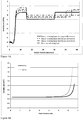
- a second example fiber preform embodiment was manufactured by densification of the outer portion of a 6500 g silica soot preform after two traverse passes of the soot preform (having an initial density of 0.45 g/cm 3 ) through a hot zone having peak temperature of 1500°C, with the heating rate of 25°C/min from 1000°C. More specifically, results for this example are shown in FIG.
- the surface area in this region ( 106B P ) was significantly lower than that of the inner portion of the perform (e.g., lower than that of the layer 106A p ).
- the preform (and thus the outer cladding region) was exposed to chlorine precursor (e.g., Cl 2 in He) and was subsequently consolidated.
- chlorine precursor e.g., Cl 2 in He
- the outer part of the outer clad layer 106B p was therefore doped with lower amount of chlorine due to the lower surface area in this region during the doping step than the inner part of the preform (layers 104 P and 106A P ).
- An optical fiber was drawn from this preform and the fiber profile obtained by such a process is shown in FIG. 2B .
- FIG 4C illustrates axial stress in the second outer cladding layer 106B as a function of stress relieving parameter ⁇ of optical fiber embodiments drawn at two different tensions.
- the three comparative examples (Comp. 1, 2 and 3) in Tables 1A-1F are also plotted. These comparative examples only have a first outer cladding layer which goes to the outer edge of the fiber (i.e., they do not have a second outer cladding layer) and the axial compression shown in these plots and tables is the first outer cladding layer.
- the optical fiber embodiments 100 having a stress relieving parameter ⁇ ⁇ 5 correspond to the second outer cladding 106B in axial tension having an axial stress of ⁇ 0.3 MPa at 50 g draw tension and ⁇ 1 at 150 g draw tension, thus the second cladding layer with ⁇ ⁇ 5 enables lower optical fiber attenuation as described above.
- the fiber 100 can be drawn at a tension of 20-400gf (i.e., at a 20-400 g draw tension).
- a number of examples of fiber embodiments 100 disclosed in Tables 1 and 2 are ITU G.652 and G.654 standards compliant.
- the fibers in Tables 1 and 2 have low attenuation at 1550 nm of ⁇ 0.19 dB/km, in some embodiments fiber attenuation is ⁇ 0.185 dB/km, in some other embodiments ⁇ 0.18 dB/km, in still some other embodiments ⁇ 0.17 dB/km.
Landscapes
- Physics & Mathematics (AREA)
- Chemical & Material Sciences (AREA)
- Engineering & Computer Science (AREA)
- Optics & Photonics (AREA)
- General Physics & Mathematics (AREA)
- Materials Engineering (AREA)
- Life Sciences & Earth Sciences (AREA)
- Organic Chemistry (AREA)
- Geochemistry & Mineralogy (AREA)
- General Chemical & Material Sciences (AREA)
- Chemical Kinetics & Catalysis (AREA)
- General Life Sciences & Earth Sciences (AREA)
- Manufacturing & Machinery (AREA)
- Glass Compositions (AREA)
Claims (14)
- Fibre optique monomode (100) comprenant :un coeur (102) comprenant du silice dopé au germanium, la quantité de germanium étant inférieure ou égale à 11% en poids et présentant un indice de réfraction relatif maximum Δ1MAX;un revêtement interne (104) entourant le coeur (102), et possédant un indice de réfraction relatif maximum Δ2 de sorte que Δ1MAX> Δ2;un revêtement externe (106) entourant le revêtement interne (104), et comprenant une première partie de revêtement externe (106A) et une deuxième partie de revêtement externe (106B) entourant la première partie de revêtement externe (106A),caractérisée en ce que la viscosité à 1 650°C de la deuxième partie de revêtement externe (106B) moins la viscosité à 1 650°C de la première partie de revêtement externe (106A) est ≥ 1 x 10⁵ kg m-1s-1 (1 x 10⁶ Poise).
- Fibre optique monomode (100) selon la revendication 1, la viscosité à 1 650°C de la deuxième partie de revêtement externe (106B) moins la viscosité à 1 650°C de la première partie de revêtement externe (106A) étant ≥ 5 x 10⁵ kg m-1s-1 (5 x 10⁶ Poise), et, de préférence, ≥ 1 x 10⁵ kg m-1s-1 (1 x 10⁶ Poise) et ≤ 1,6 x 10⁷ kg m-1s-1 (1,6 x 10⁸) Poise).
- Fibre optique monomode (100) selon une quelconque des revendications 1 - 2, la première partie de revêtement externe (106A) présentant un point de ramollissement, Tsoft-1, et la deuxième partie de revêtement externe (106B) présentant un point de ramollissement, Tsoft-2 ; et la différence entre le point de ramollissement du verre de la deuxième partie de revêtement externe (106B), Tsoft-2, et le point de ramollissement du verre de la première partie de revêtement externe (106A), Tsoft-1, est supérieure à 2°C, de préférence supérieure à 3°C, mieux encore supérieure à 7°C.
- Fibre optique monomode (100) selon une quelconque des revendications précédentes, le coeur (102) comprenant un pourcentage en poids de germanium supérieur ou égal à 2,0%.
- Fibre optique monomode (100) selon une quelconque des revendications précédentes, au moins une des conditions suivantes étant remplie :(i) l'indice de réfraction relatif maximum du coeur (102), Δ1MAX, est compris entre une valeur supérieure ou égale à 0,13% et une valeur inférieure ou égale à 0,52% ;(ii) -0,02% ≤ Δ2 ≤ 0,02%;(iii) l'épaisseur radiale du coeur (102) est comprise entre 3 microns ou plus et 10 microns ou moins ;(iv) l'épaisseur radiale du revêtement interne (104) est supérieure ou égale à 5 microns.
- Fibre optique monomode (100) selon la revendication 4, dans laquelle(i) la deuxième partie de revêtement externe (106B) comprend au moins 1 000 ppm en poids moins de chlore que la première partie de revêtement externe (106A) ; ou(ii) la concentration moyenne de chlore de la première partie de revêtement externe (106A) est comprise entre 2 000 et 20 000 ppm en poids ; ou(iii) la concentration en chlore de la deuxième partie de revêtement externe (106B) est comprise entre 0 et 6 000 ppm en poids, et la deuxième partie de revêtement externe (106B) comprend au moins 1 000 ppm en poids moins de chlore que la première partie de revêtement externe (106A).
- Fibre optique monomode (100) selon une quelconque des revendications précédentes, l'atténuation de la fibre optique monomode (100) est inférieure ou égale à 0,185 dB/km avec une longueur d'onde de 1 550 nm.
- Fibre optique monomode (100) selon une quelconque des revendications précédentes, présentant un paramètre normalisé de relaxation des contraintes Φ, Φ étant ≥ 5, et de préférence 100 ≥ Φ ≥ 5.
- Fibre optique monomode (100) selon une quelconque des revendications précédentes, la deuxième partie de revêtement externe (106B) étant sous tension, la tension produisant une contrainte axiale supérieure à 0,3 MPa, et, de préférence, supérieure à 2 MPa.
- Préforme de fibre optique (204) comprenant :(i) un coeur (102P) comprenant du silice dopé au germanium, la quantité de germanium étant inférieure ou égale à 11% en poids et présentant un indice de réfraction relatif maximum Δ1MAX;(ii) un revêtement interne (104P) entourant le coeur (102P), et possédant un indice de réfraction relatif maximum Δ2 de sorte que Δ1MAX > Δ2 ; et(iii) un revêtement externe (106P) entourant le revêtement interne, et comprenant une première partie de revêtement externe (106AP) et une deuxième partie de revêtement externe (106BP) entourant la première partie de revêtement externe (106Ap),caractérisée en ce que la viscosité à 1 650°C de la deuxième partie de revêtement externe (106BP) moins la viscosité à 1 650°C de la première partie de revêtement externe (106AP) étant ≥ 1 x 10⁵ kg m-1s-1 (1 x 10⁶ Poise).
- Préforme de fibre optique (204) selon la revendication 10, la viscosité à 1 650°C de la deuxième partie de revêtement externe (106Bp) moins la viscosité à 1 650°C de la première partie de revêtement externe (106AP) étant ≥ 5 x 10⁵ kg m-1s-1 (5 x 10⁶ Poise), et, de préférence, ≥ 1 x 10⁵ kg m-1s-1 (1 x 10⁶ Poise) et ≤ 1,6 x 10⁷ kg m-1s-1 (1,6 x 10⁸) Poise).
- Préforme de fibre optique (204) selon la revendication 10 ou 11, la première partie de revêtement externe (106AP) présentant un point de ramollissement, Tsoft-1, et la deuxième partie de revêtement externe (106Bp) présentant un point de ramollissement, Tsoft-2 ; et la différence entre le point de ramollissement du verre de la deuxième partie de revêtement externe (106BP), Tsoft-2, et le point de ramollissement du verre de la première partie de revêtement externe (106AP), Tsoft-1, est supérieure à 2°C, de préférence supérieure à 3°C, mieux encore supérieure à 7°C.
- Préforme de fibre optique (204) selon une quelconque des revendications 10-12, dans laquelle :(i) la deuxième partie de revêtement externe (106Bp) comprend au moins 1 000 ppm en poids moins de chlore que la première partie de revêtement externe (106AP) ; ou(ii) la concentration moyenne de chlore de la première partie de revêtement externe (106AP) est comprise entre 2 000 et 20 000 ppm en poids ; ou(iii) la concentration en chlore de la deuxième partie de revêtement externe (106Bp) est comprise entre 0 et 6 000 ppm en poids, et la deuxième partie de revêtement externe (106BP) comprend au moins 1 000 ppm en poids moins de chlore que la première partie de revêtement externe (106AP).
- Méthode d'étirage d'une fibre optique (100) comprenant :
l'étirage d'une fibre optique d'après la préforme (204) selon une quelconque des revendications 10-13.
Applications Claiming Priority (2)
| Application Number | Priority Date | Filing Date | Title |
|---|---|---|---|
| US201562143929P | 2015-04-07 | 2015-04-07 | |
| PCT/US2016/026325 WO2016164513A1 (fr) | 2015-04-07 | 2016-04-07 | Fibre optique monomode à faible atténuation dotée d'une couche de relâchement des contraintes, sa préforme et un procédé pour sa fabrication |
Publications (2)
| Publication Number | Publication Date |
|---|---|
| EP3280687A1 EP3280687A1 (fr) | 2018-02-14 |
| EP3280687B1 true EP3280687B1 (fr) | 2019-05-29 |
Family
ID=55802481
Family Applications (1)
| Application Number | Title | Priority Date | Filing Date |
|---|---|---|---|
| EP16717757.5A Active EP3280687B1 (fr) | 2015-04-07 | 2016-04-07 | Fibre optique monomode à faible atténuation dotée d'une couche de relâchement des contraintes, sa préforme et un procédé pour sa fabrication |
Country Status (6)
| Country | Link |
|---|---|
| US (2) | US9772445B2 (fr) |
| EP (1) | EP3280687B1 (fr) |
| JP (1) | JP6742335B2 (fr) |
| CN (1) | CN107710041B (fr) |
| DK (1) | DK3280687T3 (fr) |
| WO (1) | WO2016164513A1 (fr) |
Families Citing this family (17)
| Publication number | Priority date | Publication date | Assignee | Title |
|---|---|---|---|---|
| CN113009619B (zh) | 2015-04-15 | 2024-01-16 | 康宁股份有限公司 | 具有氟和氯共掺杂芯区域的低损耗光纤 |
| US20170097465A1 (en) * | 2015-06-30 | 2017-04-06 | Corning Incorporated | Optical fiber with large effective area and low bending loss |
| US9851501B2 (en) * | 2016-03-29 | 2017-12-26 | Corning Incorporated | Low bend loss optical fiber |
| JP7049327B2 (ja) * | 2016-09-21 | 2022-04-06 | コーニング インコーポレイテッド | 変化するクラッド屈折率を有する光ファイバ、およびそれを形成する方法 |
| CN111801609B (zh) | 2018-03-06 | 2022-09-13 | 住友电气工业株式会社 | 光纤 |
| CN108562970B (zh) * | 2018-03-21 | 2023-08-29 | 江苏亨通光纤科技有限公司 | 激光光纤及其制造方法 |
| WO2020033199A1 (fr) * | 2018-08-08 | 2020-02-13 | Corning Incorporated | Procédés de fabrication de préformes en silice dopées par halogènes, pour fibres optiques |
| US11243348B2 (en) | 2018-12-12 | 2022-02-08 | Corning Incorporated | High-density optical fiber ribbon with cladding-strengthened glass optical fibers in a common protective coating and fiber ribbon interconnects employing same |
| CN109683232A (zh) * | 2019-02-22 | 2019-04-26 | 长飞光纤光缆股份有限公司 | 具有超低衰减大有效面积的单模光纤 |
| EP3766850B1 (fr) * | 2019-07-17 | 2026-02-11 | Heraeus Quarzglas GmbH & Co. KG | Procédé de fabrication d'une fibre à coeur creux et de fabrication d'une préforme pour fibre à coeur creux |
| EP3766848B1 (fr) * | 2019-07-17 | 2022-03-02 | Heraeus Quarzglas GmbH & Co. KG | Procédé de fabrication d'une fibre à coeur creux et de fabrication d'une préforme pour une fibre à coeur creux |
| CN115515909B (zh) * | 2020-05-08 | 2024-09-24 | 康宁股份有限公司 | 具有卤素掺杂纤芯的光纤的缓慢冷却 |
| CN112230331A (zh) * | 2020-11-11 | 2021-01-15 | 江苏亨通光导新材料有限公司 | 一种全合成低损耗单模光纤 |
| CN113568092B (zh) * | 2021-07-27 | 2022-10-25 | 中国建筑材料科学研究总院有限公司 | 一种多层石英光纤及其制备方法和应用 |
| US12298553B2 (en) * | 2022-03-31 | 2025-05-13 | Microsoft Technology Licensing, Llc | Graded-index polymer optical fibre and the fabrication thereof |
| US20230314695A1 (en) * | 2022-03-31 | 2023-10-05 | Microsoft Technology Licensing, Llc | Multi-core optical fibre and fabrication thereof |
| US11931977B2 (en) | 2022-03-31 | 2024-03-19 | Microsoft Technology Licensing, Llc | Multi-core polymer optical fibre and the fabrication thereof |
Family Cites Families (20)
| Publication number | Priority date | Publication date | Assignee | Title |
|---|---|---|---|---|
| FR2650584B1 (fr) | 1989-08-02 | 1993-12-17 | Cie Generale D Electricite | Procede de fabrication d'une fibre optique a gaine dopee |
| JP2002053344A (ja) | 2000-08-07 | 2002-02-19 | Shin Etsu Chem Co Ltd | 光ファイバ用ガラス母材及び光ファイバ |
| AU773229B2 (en) | 2000-08-28 | 2004-05-20 | Sumitomo Electric Industries, Ltd. | Optical fiber and method of making the same |
| JP4093553B2 (ja) * | 2002-08-07 | 2008-06-04 | 信越化学工業株式会社 | 光ファイバプリフォームとその製造方法、及びこれを線引きして得られる光ファイバ |
| US6917740B2 (en) | 2003-05-30 | 2005-07-12 | Corning Incorporated | Optical fiber having reduced viscosity mismatch |
| CN1252498C (zh) * | 2003-07-15 | 2006-04-19 | 长飞光纤光缆有限公司 | 与正色散和正色散斜率单模光纤匹配使用的色散补偿传输光纤及用途 |
| US7715675B2 (en) * | 2003-07-18 | 2010-05-11 | Corning Incorporated | Optical fiber coating system and coated optical fiber |
| JP4999063B2 (ja) | 2006-10-19 | 2012-08-15 | 古河電気工業株式会社 | 光ファイバ |
| CN101236273B (zh) | 2008-02-29 | 2010-09-22 | 上海大学 | 单模和多模包层模干涉特种光纤及其制备方法 |
| CN101598834B (zh) * | 2009-06-26 | 2011-01-19 | 长飞光纤光缆有限公司 | 一种单模光纤及其制造方法 |
| CN101634728B (zh) * | 2009-08-18 | 2011-10-19 | 长飞光纤光缆有限公司 | 一种抗弯曲多模光纤及其制造方法 |
| US8488932B2 (en) * | 2010-02-26 | 2013-07-16 | Corning Incorporated | Optical fiber with increased mechanical strength |
| ES2727331T3 (es) * | 2010-12-23 | 2019-10-15 | Prysmian Spa | Fibra óptica monomodo de baja pérdida de macrocurvatura |
| RU2614033C2 (ru) | 2011-08-19 | 2017-03-22 | Корнинг Инкорпорейтед | Оптическое волокно с низкими изгибными потерями |
| JP6035780B2 (ja) | 2011-08-25 | 2016-11-30 | 住友電気工業株式会社 | 光ファイバ |
| US8849082B2 (en) | 2011-11-29 | 2014-09-30 | Corning Incorporated | Low bend loss optical fiber |
| US9020316B2 (en) | 2013-02-28 | 2015-04-28 | Corning Incorporated | Low attenuation optical fibers with an F-graded index core |
| CN103323908B (zh) | 2013-06-19 | 2015-07-01 | 长飞光纤光缆股份有限公司 | 一种单模光纤及其制造方法 |
| CN103399376B (zh) | 2013-08-16 | 2016-04-13 | 长飞光纤光缆股份有限公司 | 一种弯曲不敏感单模光纤及其制造方法 |
| US9658394B2 (en) | 2014-06-24 | 2017-05-23 | Corning Incorporated | Low attenuation fiber with viscosity matched core and inner clad |
-
2016
- 2016-04-06 US US15/091,852 patent/US9772445B2/en active Active
- 2016-04-07 WO PCT/US2016/026325 patent/WO2016164513A1/fr not_active Ceased
- 2016-04-07 CN CN201680032993.8A patent/CN107710041B/zh active Active
- 2016-04-07 JP JP2017552857A patent/JP6742335B2/ja not_active Expired - Fee Related
- 2016-04-07 EP EP16717757.5A patent/EP3280687B1/fr active Active
- 2016-04-07 DK DK16717757.5T patent/DK3280687T3/da active
-
2017
- 2017-05-04 US US15/586,434 patent/US9778413B2/en active Active
Non-Patent Citations (1)
| Title |
|---|
| None * |
Also Published As
| Publication number | Publication date |
|---|---|
| US9772445B2 (en) | 2017-09-26 |
| JP6742335B2 (ja) | 2020-08-19 |
| DK3280687T3 (da) | 2019-06-24 |
| US9778413B2 (en) | 2017-10-03 |
| US20170235045A1 (en) | 2017-08-17 |
| US20160299289A1 (en) | 2016-10-13 |
| WO2016164513A1 (fr) | 2016-10-13 |
| CN107710041A (zh) | 2018-02-16 |
| JP2018516217A (ja) | 2018-06-21 |
| CN107710041B (zh) | 2020-04-10 |
| EP3280687A1 (fr) | 2018-02-14 |
Similar Documents
| Publication | Publication Date | Title |
|---|---|---|
| EP3280687B1 (fr) | Fibre optique monomode à faible atténuation dotée d'une couche de relâchement des contraintes, sa préforme et un procédé pour sa fabrication | |
| US11237321B2 (en) | High chlorine content low attenuation optical fiber | |
| EP2220524B1 (fr) | Fibre optique multimode résistant à la flexion | |
| EP2786186B1 (fr) | Fibre optique à faible perte par courbure | |
| US7787731B2 (en) | Bend resistant multimode optical fiber | |
| US7680381B1 (en) | Bend insensitive optical fibers | |
| US9874686B2 (en) | Optical fiber with macrobend loss mitigating layer | |
| US20180002221A1 (en) | Low loss optical fibers with fluorine and chlorine codoped core regions | |
| US10571628B2 (en) | Low loss optical fiber with core codoped with two or more halogens | |
| US20100178504A1 (en) | Bend Insensitive Optical Fibers with Low Refractive Index Glass Rings | |
| US10228509B2 (en) | Low attenuation fiber with viscosity matched core and inner clad | |
| US11125937B2 (en) | Optical fibers having a varying clad index and methods of forming same | |
| US20150378092A1 (en) | Moatless bend-optimized multimode fiber |
Legal Events
| Date | Code | Title | Description |
|---|---|---|---|
| STAA | Information on the status of an ep patent application or granted ep patent |
Free format text: STATUS: THE INTERNATIONAL PUBLICATION HAS BEEN MADE |
|
| PUAI | Public reference made under article 153(3) epc to a published international application that has entered the european phase |
Free format text: ORIGINAL CODE: 0009012 |
|
| STAA | Information on the status of an ep patent application or granted ep patent |
Free format text: STATUS: REQUEST FOR EXAMINATION WAS MADE |
|
| 17P | Request for examination filed |
Effective date: 20171102 |
|
| AK | Designated contracting states |
Kind code of ref document: A1 Designated state(s): AL AT BE BG CH CY CZ DE DK EE ES FI FR GB GR HR HU IE IS IT LI LT LU LV MC MK MT NL NO PL PT RO RS SE SI SK SM TR |
|
| AX | Request for extension of the european patent |
Extension state: BA ME |
|
| DAV | Request for validation of the european patent (deleted) | ||
| DAX | Request for extension of the european patent (deleted) | ||
| STAA | Information on the status of an ep patent application or granted ep patent |
Free format text: STATUS: EXAMINATION IS IN PROGRESS |
|
| 17Q | First examination report despatched |
Effective date: 20180717 |
|
| REG | Reference to a national code |
Ref country code: DE Ref legal event code: R079 Ref document number: 602016014575 Country of ref document: DE Free format text: PREVIOUS MAIN CLASS: C03C0003060000 Ipc: C03B0037018000 |
|
| GRAP | Despatch of communication of intention to grant a patent |
Free format text: ORIGINAL CODE: EPIDOSNIGR1 |
|
| RIC1 | Information provided on ipc code assigned before grant |
Ipc: C03C 13/04 20060101ALI20181023BHEP Ipc: C03C 3/076 20060101ALI20181023BHEP Ipc: C03B 37/027 20060101ALI20181023BHEP Ipc: G02B 6/036 20060101ALI20181023BHEP Ipc: C03B 37/018 20060101AFI20181023BHEP Ipc: C03C 3/06 20060101ALI20181023BHEP Ipc: G02B 6/02 20060101ALI20181023BHEP Ipc: G02B 6/028 20060101ALI20181023BHEP |
|
| STAA | Information on the status of an ep patent application or granted ep patent |
Free format text: STATUS: GRANT OF PATENT IS INTENDED |
|
| INTG | Intention to grant announced |
Effective date: 20181206 |
|
| GRAS | Grant fee paid |
Free format text: ORIGINAL CODE: EPIDOSNIGR3 |
|
| GRAA | (expected) grant |
Free format text: ORIGINAL CODE: 0009210 |
|
| STAA | Information on the status of an ep patent application or granted ep patent |
Free format text: STATUS: THE PATENT HAS BEEN GRANTED |
|
| AK | Designated contracting states |
Kind code of ref document: B1 Designated state(s): AL AT BE BG CH CY CZ DE DK EE ES FI FR GB GR HR HU IE IS IT LI LT LU LV MC MK MT NL NO PL PT RO RS SE SI SK SM TR |
|
| REG | Reference to a national code |
Ref country code: GB Ref legal event code: FG4D |
|
| REG | Reference to a national code |
Ref country code: CH Ref legal event code: EP |
|
| REG | Reference to a national code |
Ref country code: AT Ref legal event code: REF Ref document number: 1138160 Country of ref document: AT Kind code of ref document: T Effective date: 20190615 |
|
| REG | Reference to a national code |
Ref country code: DE Ref legal event code: R096 Ref document number: 602016014575 Country of ref document: DE |
|
| REG | Reference to a national code |
Ref country code: DK Ref legal event code: T3 Effective date: 20190617 |
|
| REG | Reference to a national code |
Ref country code: IE Ref legal event code: FG4D |
|
| REG | Reference to a national code |
Ref country code: NL Ref legal event code: FP |
|
| REG | Reference to a national code |
Ref country code: LT Ref legal event code: MG4D |
|
| PG25 | Lapsed in a contracting state [announced via postgrant information from national office to epo] |
Ref country code: NO Free format text: LAPSE BECAUSE OF FAILURE TO SUBMIT A TRANSLATION OF THE DESCRIPTION OR TO PAY THE FEE WITHIN THE PRESCRIBED TIME-LIMIT Effective date: 20190829 Ref country code: AL Free format text: LAPSE BECAUSE OF FAILURE TO SUBMIT A TRANSLATION OF THE DESCRIPTION OR TO PAY THE FEE WITHIN THE PRESCRIBED TIME-LIMIT Effective date: 20190529 Ref country code: FI Free format text: LAPSE BECAUSE OF FAILURE TO SUBMIT A TRANSLATION OF THE DESCRIPTION OR TO PAY THE FEE WITHIN THE PRESCRIBED TIME-LIMIT Effective date: 20190529 Ref country code: PT Free format text: LAPSE BECAUSE OF FAILURE TO SUBMIT A TRANSLATION OF THE DESCRIPTION OR TO PAY THE FEE WITHIN THE PRESCRIBED TIME-LIMIT Effective date: 20190930 Ref country code: SE Free format text: LAPSE BECAUSE OF FAILURE TO SUBMIT A TRANSLATION OF THE DESCRIPTION OR TO PAY THE FEE WITHIN THE PRESCRIBED TIME-LIMIT Effective date: 20190529 Ref country code: HR Free format text: LAPSE BECAUSE OF FAILURE TO SUBMIT A TRANSLATION OF THE DESCRIPTION OR TO PAY THE FEE WITHIN THE PRESCRIBED TIME-LIMIT Effective date: 20190529 Ref country code: ES Free format text: LAPSE BECAUSE OF FAILURE TO SUBMIT A TRANSLATION OF THE DESCRIPTION OR TO PAY THE FEE WITHIN THE PRESCRIBED TIME-LIMIT Effective date: 20190529 Ref country code: LT Free format text: LAPSE BECAUSE OF FAILURE TO SUBMIT A TRANSLATION OF THE DESCRIPTION OR TO PAY THE FEE WITHIN THE PRESCRIBED TIME-LIMIT Effective date: 20190529 |
|
| PG25 | Lapsed in a contracting state [announced via postgrant information from national office to epo] |
Ref country code: GR Free format text: LAPSE BECAUSE OF FAILURE TO SUBMIT A TRANSLATION OF THE DESCRIPTION OR TO PAY THE FEE WITHIN THE PRESCRIBED TIME-LIMIT Effective date: 20190830 Ref country code: BG Free format text: LAPSE BECAUSE OF FAILURE TO SUBMIT A TRANSLATION OF THE DESCRIPTION OR TO PAY THE FEE WITHIN THE PRESCRIBED TIME-LIMIT Effective date: 20190829 Ref country code: RS Free format text: LAPSE BECAUSE OF FAILURE TO SUBMIT A TRANSLATION OF THE DESCRIPTION OR TO PAY THE FEE WITHIN THE PRESCRIBED TIME-LIMIT Effective date: 20190529 Ref country code: LV Free format text: LAPSE BECAUSE OF FAILURE TO SUBMIT A TRANSLATION OF THE DESCRIPTION OR TO PAY THE FEE WITHIN THE PRESCRIBED TIME-LIMIT Effective date: 20190529 |
|
| REG | Reference to a national code |
Ref country code: AT Ref legal event code: MK05 Ref document number: 1138160 Country of ref document: AT Kind code of ref document: T Effective date: 20190529 |
|
| PG25 | Lapsed in a contracting state [announced via postgrant information from national office to epo] |
Ref country code: CZ Free format text: LAPSE BECAUSE OF FAILURE TO SUBMIT A TRANSLATION OF THE DESCRIPTION OR TO PAY THE FEE WITHIN THE PRESCRIBED TIME-LIMIT Effective date: 20190529 Ref country code: SK Free format text: LAPSE BECAUSE OF FAILURE TO SUBMIT A TRANSLATION OF THE DESCRIPTION OR TO PAY THE FEE WITHIN THE PRESCRIBED TIME-LIMIT Effective date: 20190529 Ref country code: RO Free format text: LAPSE BECAUSE OF FAILURE TO SUBMIT A TRANSLATION OF THE DESCRIPTION OR TO PAY THE FEE WITHIN THE PRESCRIBED TIME-LIMIT Effective date: 20190529 Ref country code: EE Free format text: LAPSE BECAUSE OF FAILURE TO SUBMIT A TRANSLATION OF THE DESCRIPTION OR TO PAY THE FEE WITHIN THE PRESCRIBED TIME-LIMIT Effective date: 20190529 Ref country code: AT Free format text: LAPSE BECAUSE OF FAILURE TO SUBMIT A TRANSLATION OF THE DESCRIPTION OR TO PAY THE FEE WITHIN THE PRESCRIBED TIME-LIMIT Effective date: 20190529 |
|
| PG25 | Lapsed in a contracting state [announced via postgrant information from national office to epo] |
Ref country code: SM Free format text: LAPSE BECAUSE OF FAILURE TO SUBMIT A TRANSLATION OF THE DESCRIPTION OR TO PAY THE FEE WITHIN THE PRESCRIBED TIME-LIMIT Effective date: 20190529 |
|
| REG | Reference to a national code |
Ref country code: DE Ref legal event code: R097 Ref document number: 602016014575 Country of ref document: DE |
|
| PG25 | Lapsed in a contracting state [announced via postgrant information from national office to epo] |
Ref country code: TR Free format text: LAPSE BECAUSE OF FAILURE TO SUBMIT A TRANSLATION OF THE DESCRIPTION OR TO PAY THE FEE WITHIN THE PRESCRIBED TIME-LIMIT Effective date: 20190529 |
|
| PLBE | No opposition filed within time limit |
Free format text: ORIGINAL CODE: 0009261 |
|
| STAA | Information on the status of an ep patent application or granted ep patent |
Free format text: STATUS: NO OPPOSITION FILED WITHIN TIME LIMIT |
|
| PG25 | Lapsed in a contracting state [announced via postgrant information from national office to epo] |
Ref country code: PL Free format text: LAPSE BECAUSE OF FAILURE TO SUBMIT A TRANSLATION OF THE DESCRIPTION OR TO PAY THE FEE WITHIN THE PRESCRIBED TIME-LIMIT Effective date: 20190529 |
|
| 26N | No opposition filed |
Effective date: 20200303 |
|
| PG25 | Lapsed in a contracting state [announced via postgrant information from national office to epo] |
Ref country code: SI Free format text: LAPSE BECAUSE OF FAILURE TO SUBMIT A TRANSLATION OF THE DESCRIPTION OR TO PAY THE FEE WITHIN THE PRESCRIBED TIME-LIMIT Effective date: 20190529 |
|
| PG25 | Lapsed in a contracting state [announced via postgrant information from national office to epo] |
Ref country code: MC Free format text: LAPSE BECAUSE OF FAILURE TO SUBMIT A TRANSLATION OF THE DESCRIPTION OR TO PAY THE FEE WITHIN THE PRESCRIBED TIME-LIMIT Effective date: 20190529 |
|
| REG | Reference to a national code |
Ref country code: CH Ref legal event code: PL |
|
| PG25 | Lapsed in a contracting state [announced via postgrant information from national office to epo] |
Ref country code: LI Free format text: LAPSE BECAUSE OF NON-PAYMENT OF DUE FEES Effective date: 20200430 Ref country code: CH Free format text: LAPSE BECAUSE OF NON-PAYMENT OF DUE FEES Effective date: 20200430 Ref country code: LU Free format text: LAPSE BECAUSE OF NON-PAYMENT OF DUE FEES Effective date: 20200407 |
|
| REG | Reference to a national code |
Ref country code: BE Ref legal event code: MM Effective date: 20200430 |
|
| PG25 | Lapsed in a contracting state [announced via postgrant information from national office to epo] |
Ref country code: BE Free format text: LAPSE BECAUSE OF NON-PAYMENT OF DUE FEES Effective date: 20200430 |
|
| PG25 | Lapsed in a contracting state [announced via postgrant information from national office to epo] |
Ref country code: IE Free format text: LAPSE BECAUSE OF NON-PAYMENT OF DUE FEES Effective date: 20200407 |
|
| PG25 | Lapsed in a contracting state [announced via postgrant information from national office to epo] |
Ref country code: MT Free format text: LAPSE BECAUSE OF FAILURE TO SUBMIT A TRANSLATION OF THE DESCRIPTION OR TO PAY THE FEE WITHIN THE PRESCRIBED TIME-LIMIT Effective date: 20190529 Ref country code: CY Free format text: LAPSE BECAUSE OF FAILURE TO SUBMIT A TRANSLATION OF THE DESCRIPTION OR TO PAY THE FEE WITHIN THE PRESCRIBED TIME-LIMIT Effective date: 20190529 |
|
| PG25 | Lapsed in a contracting state [announced via postgrant information from national office to epo] |
Ref country code: MK Free format text: LAPSE BECAUSE OF FAILURE TO SUBMIT A TRANSLATION OF THE DESCRIPTION OR TO PAY THE FEE WITHIN THE PRESCRIBED TIME-LIMIT Effective date: 20190529 Ref country code: IS Free format text: LAPSE BECAUSE OF FAILURE TO SUBMIT A TRANSLATION OF THE DESCRIPTION OR TO PAY THE FEE WITHIN THE PRESCRIBED TIME-LIMIT Effective date: 20190929 |
|
| P01 | Opt-out of the competence of the unified patent court (upc) registered |
Effective date: 20230527 |
|
| PGFP | Annual fee paid to national office [announced via postgrant information from national office to epo] |
Ref country code: DE Payment date: 20250317 Year of fee payment: 10 |
|
| PGFP | Annual fee paid to national office [announced via postgrant information from national office to epo] |
Ref country code: IT Payment date: 20250414 Year of fee payment: 10 |
|
| PGFP | Annual fee paid to national office [announced via postgrant information from national office to epo] |
Ref country code: GB Payment date: 20260320 Year of fee payment: 11 |
|
| PGFP | Annual fee paid to national office [announced via postgrant information from national office to epo] |
Ref country code: DK Payment date: 20260330 Year of fee payment: 11 |
|
| PGFP | Annual fee paid to national office [announced via postgrant information from national office to epo] |
Ref country code: NL Payment date: 20260323 Year of fee payment: 11 |
|
| PGFP | Annual fee paid to national office [announced via postgrant information from national office to epo] |
Ref country code: FR Payment date: 20260317 Year of fee payment: 11 |