EP3280949B1 - Lineare beleuchtungsvorrichtung - Google Patents
Lineare beleuchtungsvorrichtung Download PDFInfo
- Publication number
- EP3280949B1 EP3280949B1 EP16723160.4A EP16723160A EP3280949B1 EP 3280949 B1 EP3280949 B1 EP 3280949B1 EP 16723160 A EP16723160 A EP 16723160A EP 3280949 B1 EP3280949 B1 EP 3280949B1
- Authority
- EP
- European Patent Office
- Prior art keywords
- cylindrical lens
- reflector
- sources
- lens
- plane
- Prior art date
- Legal status (The legal status is an assumption and is not a legal conclusion. Google has not performed a legal analysis and makes no representation as to the accuracy of the status listed.)
- Not-in-force
Links
- 230000003287 optical effect Effects 0.000 claims description 21
- 238000010168 coupling process Methods 0.000 claims description 5
- 238000005859 coupling reaction Methods 0.000 claims description 5
- CERQOIWHTDAKMF-UHFFFAOYSA-M Methacrylate Chemical compound CC(=C)C([O-])=O CERQOIWHTDAKMF-UHFFFAOYSA-M 0.000 claims description 3
- XAGFODPZIPBFFR-UHFFFAOYSA-N aluminium Chemical compound [Al] XAGFODPZIPBFFR-UHFFFAOYSA-N 0.000 description 6
- 229910052782 aluminium Inorganic materials 0.000 description 6
- 239000004411 aluminium Substances 0.000 description 6
- 230000000694 effects Effects 0.000 description 6
- 238000010586 diagram Methods 0.000 description 4
- 238000009792 diffusion process Methods 0.000 description 2
- 239000011521 glass Substances 0.000 description 2
- 239000000758 substrate Substances 0.000 description 2
- 230000006978 adaptation Effects 0.000 description 1
- 239000003086 colorant Substances 0.000 description 1
- 230000008878 coupling Effects 0.000 description 1
- 230000001419 dependent effect Effects 0.000 description 1
- 238000005286 illumination Methods 0.000 description 1
- 238000003754 machining Methods 0.000 description 1
- 239000000463 material Substances 0.000 description 1
- 238000012986 modification Methods 0.000 description 1
- 230000004048 modification Effects 0.000 description 1
- 238000005375 photometry Methods 0.000 description 1
- 229920003023 plastic Polymers 0.000 description 1
- 229920003229 poly(methyl methacrylate) Polymers 0.000 description 1
- 239000004926 polymethyl methacrylate Substances 0.000 description 1
- 238000000926 separation method Methods 0.000 description 1
- 239000000725 suspension Substances 0.000 description 1
Images


Classifications
-
- F—MECHANICAL ENGINEERING; LIGHTING; HEATING; WEAPONS; BLASTING
- F21—LIGHTING
- F21V—FUNCTIONAL FEATURES OR DETAILS OF LIGHTING DEVICES OR SYSTEMS THEREOF; STRUCTURAL COMBINATIONS OF LIGHTING DEVICES WITH OTHER ARTICLES, NOT OTHERWISE PROVIDED FOR
- F21V5/00—Refractors for light sources
- F21V5/04—Refractors for light sources of lens shape
- F21V5/043—Refractors for light sources of lens shape the lens having cylindrical faces, e.g. rod lenses, toric lenses
-
- F—MECHANICAL ENGINEERING; LIGHTING; HEATING; WEAPONS; BLASTING
- F21—LIGHTING
- F21S—NON-PORTABLE LIGHTING DEVICES; SYSTEMS THEREOF; VEHICLE LIGHTING DEVICES SPECIALLY ADAPTED FOR VEHICLE EXTERIORS
- F21S4/00—Lighting devices or systems using a string or strip of light sources
- F21S4/20—Lighting devices or systems using a string or strip of light sources with light sources held by or within elongate supports
-
- F—MECHANICAL ENGINEERING; LIGHTING; HEATING; WEAPONS; BLASTING
- F21—LIGHTING
- F21V—FUNCTIONAL FEATURES OR DETAILS OF LIGHTING DEVICES OR SYSTEMS THEREOF; STRUCTURAL COMBINATIONS OF LIGHTING DEVICES WITH OTHER ARTICLES, NOT OTHERWISE PROVIDED FOR
- F21V13/00—Producing particular characteristics or distribution of the light emitted by means of a combination of elements specified in two or more of main groups F21V1/00 - F21V11/00
- F21V13/02—Combinations of only two kinds of elements
- F21V13/04—Combinations of only two kinds of elements the elements being reflectors and refractors
-
- F—MECHANICAL ENGINEERING; LIGHTING; HEATING; WEAPONS; BLASTING
- F21—LIGHTING
- F21V—FUNCTIONAL FEATURES OR DETAILS OF LIGHTING DEVICES OR SYSTEMS THEREOF; STRUCTURAL COMBINATIONS OF LIGHTING DEVICES WITH OTHER ARTICLES, NOT OTHERWISE PROVIDED FOR
- F21V13/00—Producing particular characteristics or distribution of the light emitted by means of a combination of elements specified in two or more of main groups F21V1/00 - F21V11/00
- F21V13/12—Combinations of only three kinds of elements
- F21V13/14—Combinations of only three kinds of elements the elements being filters or photoluminescent elements, reflectors and refractors
-
- F—MECHANICAL ENGINEERING; LIGHTING; HEATING; WEAPONS; BLASTING
- F21—LIGHTING
- F21V—FUNCTIONAL FEATURES OR DETAILS OF LIGHTING DEVICES OR SYSTEMS THEREOF; STRUCTURAL COMBINATIONS OF LIGHTING DEVICES WITH OTHER ARTICLES, NOT OTHERWISE PROVIDED FOR
- F21V7/00—Reflectors for light sources
- F21V7/005—Reflectors for light sources with an elongated shape to cooperate with linear light sources
-
- G—PHYSICS
- G02—OPTICS
- G02B—OPTICAL ELEMENTS, SYSTEMS OR APPARATUS
- G02B19/00—Condensers, e.g. light collectors or similar non-imaging optics
- G02B19/0004—Condensers, e.g. light collectors or similar non-imaging optics characterised by the optical means employed
- G02B19/0009—Condensers, e.g. light collectors or similar non-imaging optics characterised by the optical means employed having refractive surfaces only
- G02B19/0014—Condensers, e.g. light collectors or similar non-imaging optics characterised by the optical means employed having refractive surfaces only at least one surface having optical power
-
- G—PHYSICS
- G02—OPTICS
- G02B—OPTICAL ELEMENTS, SYSTEMS OR APPARATUS
- G02B19/00—Condensers, e.g. light collectors or similar non-imaging optics
- G02B19/0033—Condensers, e.g. light collectors or similar non-imaging optics characterised by the use
- G02B19/0047—Condensers, e.g. light collectors or similar non-imaging optics characterised by the use for use with a light source
- G02B19/0061—Condensers, e.g. light collectors or similar non-imaging optics characterised by the use for use with a light source the light source comprising a LED
- G02B19/0066—Condensers, e.g. light collectors or similar non-imaging optics characterised by the use for use with a light source the light source comprising a LED in the form of an LED array
-
- G—PHYSICS
- G02—OPTICS
- G02B—OPTICAL ELEMENTS, SYSTEMS OR APPARATUS
- G02B3/00—Simple or compound lenses
- G02B3/02—Simple or compound lenses with non-spherical faces
- G02B3/06—Simple or compound lenses with non-spherical faces with cylindrical or toric faces
-
- F—MECHANICAL ENGINEERING; LIGHTING; HEATING; WEAPONS; BLASTING
- F21—LIGHTING
- F21Y—INDEXING SCHEME ASSOCIATED WITH SUBCLASSES F21K, F21L, F21S and F21V, RELATING TO THE FORM OR THE KIND OF THE LIGHT SOURCES OR OF THE COLOUR OF THE LIGHT EMITTED
- F21Y2103/00—Elongate light sources, e.g. fluorescent tubes
- F21Y2103/10—Elongate light sources, e.g. fluorescent tubes comprising a linear array of point-like light-generating elements
-
- F—MECHANICAL ENGINEERING; LIGHTING; HEATING; WEAPONS; BLASTING
- F21—LIGHTING
- F21Y—INDEXING SCHEME ASSOCIATED WITH SUBCLASSES F21K, F21L, F21S and F21V, RELATING TO THE FORM OR THE KIND OF THE LIGHT SOURCES OR OF THE COLOUR OF THE LIGHT EMITTED
- F21Y2115/00—Light-generating elements of semiconductor light sources
- F21Y2115/10—Light-emitting diodes [LED]
Definitions
- This invention relates to a linear lighting apparatus, i.e., of elongated shape, with a plurality of lighting sources, in particular of the LED type, arranged in line with a certain step of distance from each other.
- the linear boards accommodate and manage LEDs of different colours to implement RGB or CTC (Colour Temperature Change) lighting.
- the LEDs mounted on these cards can be of various types but, to obtain high luminous power, high-power, mono- or multi-chip LEDs are normally used.
- the heat produced is concentrated in discrete points and requires the use of circuit boards printed on an aluminium substrate.
- the high cost of these boards is mainly due to the large aluminium surfaces of the printed circuit board.
- a major problem is that of uniformity of emission near the apparatus. For example, in the oblique illumination of a wall, excessive distances between the LEDs are to be avoided because they produce unwanted bright strips or visibly separated beams. More densely populated mid-power boards are advantageous for this aspect as well.
- the short-step mounting of the LEDs can create significant problems in the case of collimating optics, i.e., to produce narrow beams.
- the light distribution should be fundamentally blade of light, narrow only in the direction transverse to the apparatus, as wide and uniform as possible longitudinally to it.
- LEDs which are almost always Lambertian sources
- An embodiment provides for the use of single and lined filter optics: for each LED, a lens or a reflector closes the beam in all directions, then this is expanded in the longitudinal direction with a filter with grooves or with a machining of the lens itself with lines.
- the optical dimensions are linked to the step of the LEDs; furthermore, there is the limit of about 60° on the longitudinal opening effect of the beam.
- Another embodiment provides the use of collimating optics of the linear type, wherein there is a single optics for all LEDs simultaneously, with an effect independent on the distance between the LEDs.
- the longitudinal uniformity of the beam is here the best because it does not intervene on the rays in that direction.
- this technical solution can be achieved with a parabolic reflector having two long reflective elements profiled at the sides of the row of LEDs.
- This embodiment has the disadvantage that part of the luminous flow (in particular the direct light) remains ingested and "dirties" the beam.
- a lens with a suitable profile such as a TIR lens
- the realisation of a lens of this type is complex and expensive.
- the purpose of this invention is to provide a linear lighting apparatus capable of obviating the drawbacks mentioned above with reference to known art, in particular having an optics independent of the distance between the lighting sources, therefore able to operate indifferently with boards of different light power, having a high collimating power, and that is still simple and inexpensive to produce and assemble.
- the linear lighting apparatus includes a plurality of lighting sources, for example of the LED type, aligned along a main axis of the apparatus.
- a cylindrical lens with its axis parallel to the main axis of the apparatus is suitable to receive the majority of the light emission generated by the lighting sources and to emit a substantially collimated light beam. At least the light emission that does not undergo refraction by the cylindrical lens is reflected by a reflector.
- the lighting sources are placed also in the focus of the reflector.
- the reflector is a parabolic reflector.
- the parabolic reflector has a pair of longitudinal walls that extend parallel to the axis of the apparatus at the sides of the row of lighting sources.
- the cylindrical lens is positioned at least partially in the cavity delimited by the reflector.
- the lighting apparatus is thus particularly compact.
- the sources plane as a plane on which the lighting sources lie, for example, a plane defined by an electronic board on which the sources are mounted, in an embodiment, the axis of the apparatus and the axis of the cylindrical lens belong to a transversal plane perpendicular to said sources plane.
- the axis of the apparatus is external to a transversal plane on which the axis of the cylindrical lens lies and perpendicular to said sources plane.
- the reflector is shaped so as to reflect the rays in the same direction as the collimated beam exiting from the cylindrical lens.
- the lighting apparatus comprises a holographic filter suitable to act on the collimated light beam emitted by the cylindrical lens.
- the holographic filter is supported by the reflector itself.
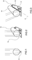
- the idea underlying the invention originates from the principle of the full spherical lens ( Figure 1 ).
- a linear apparatus 10 i.e., having a plurality of lighting sources 12 arranged side by side along a main development axis X of the apparatus
- the cylindrical lens is obtained by "extruding" the same circular section of the spherical lens ( Figures 2 and 3 ). By placing the row of lighting sources 12 in parallel and at the correct focal distance from the cylindrical lens 14, a very narrow blade of light is obtained.
- cylindrical lens 14 you can use a simple rod made of methacrylate (PMMA).
- the rod has a diameter of between 10 mm and 20 mm.
- Transparent methacrylate rods are very common and relatively inexpensive objects, produced and used in various sizes, for example in furnishing for ornamental purposes.
- the lighting apparatus further comprises a reflector 16 suitable for reflecting the light rays not intercepted by the cylindrical lens 14. Preferably, these rays are reflected in the same direction as the collimated beam exiting from the cylindrical lens 14.
- the reflector 16 is a parabolic reflector and the lighting sources 12 are placed in the focus of the parabolic reflector.
- the parabolic reflector has a pair of longitudinal walls 16' that extend parallel to the axis of the apparatus at the sides of the row of lighting sources 12.
- the reflector 16 is made of mirrorlike, high-reflectance anodised aluminium.
- the cylindrical lens 14 is positioned at least partially in the longitudinal 18 cavity delimited by the reflector 16.
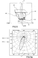
- calibrated-diffusion filter 20 also known as a holographic filter.
- the holographic filter 20 is supported by the reflector itself.
- the filter is fixed to the reflector edges.
- the filter 20 has an aperture of 10°.
- Figure 4a shows, using the C/y reference coordinate system commonly used to describe light emissions, the transverse light distribution (continuous line), i.e., in the plane C0-C180 orthogonal to the main axis of the apparatus, and the longitudinal light distribution (in dashed line), or in the plane C90-C270 parallel to the main axis of the apparatus.
- the optical system described offers the possibility of further implementations. For example, by laterally moving the cylindrical lens 14 with respect to the row of lighting sources 12 (or vice versa), even by a few millimetres, one obtains an inclination effect of the blade of light with respect to the plane perpendicular to the plane on which lie the lighting sources 12, i.e., an inclination with respect to the optical axis Y of the system ( Figures 3 , 5 and 5a ). Such an asymmetric beam is particularly suitable for the lighting effect of vertical planes.
- the LED board is a high-power monochromatic or multi-chromatic board (with RGB colour-change, RGBW or CTC function).
- FIGS 6, 6a and 7 show a practical embodiment example of the lighting apparatus according to the invention.
- the lighting apparatus comprises an inner profile 30, for example made of aluminium, suitable to support the optical elements of the apparatus.
- the inner profile 30 is housed in a longitudinal chamber 32 of an outer profile 34, for example, also it made of aluminium, which forms the housing of the lighting apparatus and which supports a closing glass 36 placed to close the emission window of the light flow.
- the inner profile 30 forms a support surface 302 for the electronic board 12' on which a row of LEDs 12 is mounted.
- the inner profile 30 forms at least two channels 304,304' which extend parallel to the development axis X of the lighting apparatus.
- the electronic board 12' are formed at least two rows of fixing holes 124,124' for the fixing screws 122.
- the row of LEDs 12 is positioned between the two rows of fixing holes 124,124'.
- only one of these rows of fixing holes 124,124', and of the corresponding channels, is engaged by the fixing screws 122 at a time.
- the channels 304,304' are positioned at a different distance from the optical axis Y.
- the two rows of fixing holes 124,124' are preferably equidistant from the optical axis Y.
- the row of fixing screws 122 is screwed into the other channel 304, as illustrated for example in Figure 6a , the row of LEDs 12 is offset, i.e., translated laterally with respect to the optical axis Y, so as to realise, together with the reflector for asymmetric beam 16", the configuration corresponding to Figure 5 .
- the channels 304,304' may be made equidistant from the optical axis Y, differentiating instead the distance of the fixing holes 124,124' with respect to this optical axis Y.
- the inner profile 30 forms two side walls 306 which delimit, jointly with the support surface 302, a longitudinal chamber 305 in which are housed the reflector 16,16" and the cylindrical lens 14.
- the side walls 306 support, longitudinally spaced between them, at least two lens-holder plates 38, for example made of a transparent plastic material.
- Each lens-holder plate 38 is shaped so as to realise a shape-coupling with the cylindrical lens 14 to support such a cylindrical lens 14.
- each lens-holder plate 38 is formed of a C-shaped seat, suitable to snap-couple with the cylindrical lens 14.
- each lens-holder plate 38 is supported only at its lateral ends 38' by the side walls 306 of the inner profile 30, so as to be suspended on the support plane 302 of the electronic board 12'.
- slots 162 that allow the passage of the lens-holder plates 38 through these walls 16'.
- each side wall 306 is formed a longitudinal seat 308 on which is slidingly received and with shape-coupling a respective lateral end 38' of the lens-holder plate 38.
- each longitudinal seat 308 has a shape of a C shape open towards the longitudinal chamber 305, and the lateral ends 38' of the lens-holder plates 38 have a cylindrical shape.
- each lens-holder plate 38 can be inserted from one end of the inner profile 30 and made to slide along the longitudinal seats 308 so as to be placed in the desired position.
Landscapes
- Physics & Mathematics (AREA)
- Engineering & Computer Science (AREA)
- General Engineering & Computer Science (AREA)
- General Physics & Mathematics (AREA)
- Optics & Photonics (AREA)
- Non-Portable Lighting Devices Or Systems Thereof (AREA)
- Securing Globes, Refractors, Reflectors Or The Like (AREA)
Claims (15)
- Lineare Beleuchtungsvorrichtung, umfassend eine Mehrzahl von Beleuchtungsquellen (12), die entlang einer Hauptachse der Vorrichtung (X) ausgerichtet sind, eine Zylinderlinse (14) mit ihrer Achse parallel zu der Hauptachse der Vorrichtung, wobei die Zylinderlinse geeignet ist, den größten Teil der von den Lichtquellen erzeugten Lichtemission aufzunehmen und einen im Wesentlichen kollimierten Lichtstrahl zu emittieren, einen Reflektor (16;16"), der geeignet ist, zumindest einen Teil der Lichtemission zu reflektieren, der nicht durch die Zylinderlinse gebrochen wird, und ein Innenprofil (30), das eine Stützt- bzw. Trägerfläche (302) für die Lichtquellen (12) bildet, und zwei Seitenwände (306), die zusammen mit der Stützfläche (302) eine Längskammer (305) begrenzen, in der der Reflektor (16;16") und die Zylinderlinse (14) untergebracht sind, wobei die Seitenwände (306) longitudinal zwischen diesen beabstandet zumindest zwei Linsenhalterplatten (38) stützen bzw. tragen, die so geformt sind, dass sie eine Formkopplung mit der Zylinderlinse (14) realisieren, um die Zylinderlinse (14) zu stützen bzw. zu tragen.
- Vorrichtung nach dem vorhergehenden Anspruch, wobei die Lichtquellen (12) im Fokus der Zylinderlinse (14) platziert sind.
- Vorrichtung nach Anspruch 1 oder 2, wobei die Lichtquellen (12) im Fokus des Reflektors (16; 16") platziert sind.
- Vorrichtung nach einem der vorhergehenden Ansprüche, wobei der Reflektor (16) ein Parabolreflektor ist.
- Vorrichtung nach einem der vorhergehenden Ansprüche, wobei die Zylinderlinse in dem durch den Reflektor begrenzten Hohlraum positioniert ist.
- Vorrichtung nach einem der vorhergehenden Ansprüche, wobei die Zylinderlinse aus einem Methacrylatstab erhalten wird, wobei der Stab einen Durchmesser zwischen 10 mm und 20 mm aufweist.
- Vorrichtung nach einem der vorhergehenden Ansprüche, wobei die Beleuchtungsquellen auf einer Quellenebene liegen und wobei die Achse der Vorrichtung und die Achse der Zylinderlinse zu einer Querebene gehören, die senkrecht zu der Quellenebene ist.
- Vorrichtung nach einem der Ansprüche 1-6, wobei die Lichtquellen auf einer Quellenebene liegen und wobei die Achse der Vorrichtung außerhalb einer Querebene ist, auf der die Achse der Zylinderlinse liegt, und senkrecht zu der Quellenebene ist.
- Vorrichtung nach dem vorhergehenden Anspruch, wobei der Reflektor so geformt ist, dass er die Strahlen in der gleichen Richtung wie der bzw. den kolli-mierte(n) Strahl reflektiert, der aus der Zylinderlinse austritt.
- Vorrichtung nach einem der vorhergehenden Ansprüche, ferner umfassend einen holographischen Filter (20), das geeignet ist, auf den von der Zylinderlinse emittierten kollimierten Lichtstrahl einzuwirken, wobei der holographische Filter (20) durch den Reflektor (16) gestützt bzw. getragen ist.
- Vorrichtung nach einem der vorhergehenden Ansprüche, wobei die Lichtquellen LED-Lichtquellen sind, die in einer linearen Konfiguration auf einer elektronischen Platine (12') montiert sind.
- Vorrichtung nach einem der vorhergehenden Ansprüche, wobei das Innenprofil (30) eine Stütz- bzw. Trägerfläche (302) bildet, auf der eine elektronische Platine (12') aufliegt, auf der eine Reihe von Lichtquellen (12) montiert ist, und wobei sich unter der elektronischen Platine (12') zumindest zwei Kanäle (304, 304') befinden, die sich parallel zu der Hauptachse der Vorrichtung (X) erstrecken und die geeignet sind, eine Reihe von Befestigungsschrauben (122) aufzunehmen, die die elektronische Platine (12') an der Stützfläche (302) verriegeln, wobei in der elektronischen Platine (12') zumindest zwei Reihen von Befestigungslöchern (124, 124') für die Befestigungsschrauben (122) ausgebildet sind, wobei die Kanäle (304, 304') oder die Befestigungslochreihen (124, 124') in einem unterschiedlichen Abstand von der optischen Achse (Y) positioniert sind, die durch die Mitte der Zylinderlinse (14) verläuft und die senkrecht zu der Stützebene (302) der Vorrichtung ist, die durch die Mitte verläuft, und wobei nur ein Kanal und eine jeweilige Reihe von Befestigungslöchern von den Befestigungsschrauben in Eingriff genommen werden, um zumindest zwei unterschiedlichen Positionen der Reihe von Lichtquellen (12) in Bezug auf die optische Achse (Y) in Abhängigkeit von dem Kanal-Loch-Paar zu identifizieren, das von den Befestigungsschrauben in Eingriff genommen wird.
- Vorrichtung nach einem der vorhergehenden Ansprüche, wobei jede Linsenhalterplatte (38) nur an ihren seitlichen Enden (38') durch die Seitenwänden (306) des Innenprofils (30) gestützt ist, um auf der Stützebene (302) aufgehängt zu sein.
- Vorrichtung nach einem der vorhergehenden Ansprüche, wobei in den Wänden (16') des Reflektors (16;16") Schlitze (162) ausgebildet sind, die den Durchtritt der Linsenhalterplatten (38) diese Wände (16') erlauben.
- Vorrichtung nach einem der vorhergehenden Ansprüche, wobei in jeder Seitenwand (306) ein Längssitz (308) ausgebildet ist, auf dem ein jeweiliges seitliches Ende (38') der Linsenhalterplatte (38) gleitend und formschlüssig aufgenommen ist.
Applications Claiming Priority (2)
| Application Number | Priority Date | Filing Date | Title |
|---|---|---|---|
| ITBS20150059 | 2015-04-10 | ||
| PCT/IB2016/052013 WO2016162849A1 (en) | 2015-04-10 | 2016-04-08 | Linear lighting apparatus |
Publications (2)
| Publication Number | Publication Date |
|---|---|
| EP3280949A1 EP3280949A1 (de) | 2018-02-14 |
| EP3280949B1 true EP3280949B1 (de) | 2020-07-01 |
Family
ID=53673145
Family Applications (1)
| Application Number | Title | Priority Date | Filing Date |
|---|---|---|---|
| EP16723160.4A Not-in-force EP3280949B1 (de) | 2015-04-10 | 2016-04-08 | Lineare beleuchtungsvorrichtung |
Country Status (3)
| Country | Link |
|---|---|
| US (1) | US10145534B2 (de) |
| EP (1) | EP3280949B1 (de) |
| WO (1) | WO2016162849A1 (de) |
Families Citing this family (2)
| Publication number | Priority date | Publication date | Assignee | Title |
|---|---|---|---|---|
| CN114901990B (zh) | 2020-01-02 | 2025-09-26 | 昕诺飞控股有限公司 | 照明设备、灯具及冰箱 |
| FR3125863B1 (fr) | 2021-07-30 | 2026-02-06 | Obsta | Balise de signalisation à réflecteurs |
Family Cites Families (6)
| Publication number | Priority date | Publication date | Assignee | Title |
|---|---|---|---|---|
| DE102005035720A1 (de) * | 2005-07-29 | 2007-02-08 | Zumtobel Staff Gmbh | Leuchte mit einer langgestreckten Lichtquelle und mit einem ebenfalls langgestreckten Lichtleitelement |
| DE202009008684U1 (de) * | 2008-08-14 | 2010-02-25 | h.e.l - Lichttechnik GbR (vertretungsberechtigte Gesellschafterin: Stefanie Zenz, 49393 Lohne) | LED-Beleuchtung mit optischem Verstärker in Stabform, lichtstreuend |
| WO2010026279A1 (en) * | 2008-09-03 | 2010-03-11 | Artequa Oy | Illuminating device |
| JP2011054373A (ja) * | 2009-09-01 | 2011-03-17 | Sony Corp | 可変照明装置 |
| EP2402648A1 (de) * | 2010-07-01 | 2012-01-04 | Koninklijke Philips Electronics N.V. | TL-LED-Nachrüstmodul mit außen abgedichteter Glasröhre |
| JP6250660B2 (ja) * | 2012-06-28 | 2017-12-20 | インテマティックス・コーポレーションIntematix Corporation | ランプ及び光学部品の製造方法 |
-
2016
- 2016-04-08 EP EP16723160.4A patent/EP3280949B1/de not_active Not-in-force
- 2016-04-08 WO PCT/IB2016/052013 patent/WO2016162849A1/en not_active Ceased
- 2016-04-08 US US15/565,455 patent/US10145534B2/en not_active Expired - Fee Related
Non-Patent Citations (1)
| Title |
|---|
| None * |
Also Published As
| Publication number | Publication date |
|---|---|
| WO2016162849A1 (en) | 2016-10-13 |
| EP3280949A1 (de) | 2018-02-14 |
| US20180119921A1 (en) | 2018-05-03 |
| US10145534B2 (en) | 2018-12-04 |
Similar Documents
| Publication | Publication Date | Title |
|---|---|---|
| US9046225B2 (en) | Lighting system with improved illumination distribution | |
| US9335462B2 (en) | Luminaire module with multiple light guide elements | |
| US10215911B2 (en) | Lighting assembly | |
| US8678605B2 (en) | Two-component direct-indirect lighting system | |
| EP2998638B1 (de) | Verfahren und system für led-lampe mit interner optik zur spezifischen lichtverteilung | |
| EP3260768A1 (de) | Led-stab-beleuchtung und ausstellungsschrank damit | |
| US9395478B2 (en) | Blade of light luminaire | |
| EP1970620A1 (de) | Beleuchtungsvorrichtung | |
| TW200916692A (en) | LED-based luminaire with adjustable beam shape | |
| RU2013115918A (ru) | Устройство для местного освещения | |
| US9360172B2 (en) | Arrangement for emitting light | |
| US9200782B1 (en) | Multi-directional lighting with single orientation light source | |
| EP3280949B1 (de) | Lineare beleuchtungsvorrichtung | |
| JP6709345B1 (ja) | 照明器具 | |
| US20160223164A1 (en) | Wall washer lighting system with light emitter, optical lens and reflector | |
| EP3963253B1 (de) | Lichtemittierende vorrichtung | |
| RU187621U1 (ru) | Оптическая система с мультилинзой светодиодного светильника | |
| RU2657466C2 (ru) | Осветительная полоса, осветительная система, опорный панельный элемент и модульная панельная система | |
| US20240302026A1 (en) | A light fixture | |
| CN104566212A (zh) | 透镜 | |
| ITBS20150008U1 (it) | Apparecchio di illuminazione lineare |
Legal Events
| Date | Code | Title | Description |
|---|---|---|---|
| STAA | Information on the status of an ep patent application or granted ep patent |
Free format text: STATUS: THE INTERNATIONAL PUBLICATION HAS BEEN MADE |
|
| PUAI | Public reference made under article 153(3) epc to a published international application that has entered the european phase |
Free format text: ORIGINAL CODE: 0009012 |
|
| STAA | Information on the status of an ep patent application or granted ep patent |
Free format text: STATUS: REQUEST FOR EXAMINATION WAS MADE |
|
| 17P | Request for examination filed |
Effective date: 20171006 |
|
| AK | Designated contracting states |
Kind code of ref document: A1 Designated state(s): AL AT BE BG CH CY CZ DE DK EE ES FI FR GB GR HR HU IE IS IT LI LT LU LV MC MK MT NL NO PL PT RO RS SE SI SK SM TR |
|
| AX | Request for extension of the european patent |
Extension state: BA ME |
|
| DAV | Request for validation of the european patent (deleted) | ||
| DAX | Request for extension of the european patent (deleted) | ||
| GRAP | Despatch of communication of intention to grant a patent |
Free format text: ORIGINAL CODE: EPIDOSNIGR1 |
|
| STAA | Information on the status of an ep patent application or granted ep patent |
Free format text: STATUS: GRANT OF PATENT IS INTENDED |
|
| INTG | Intention to grant announced |
Effective date: 20190823 |
|
| GRAS | Grant fee paid |
Free format text: ORIGINAL CODE: EPIDOSNIGR3 |
|
| GRAA | (expected) grant |
Free format text: ORIGINAL CODE: 0009210 |
|
| STAA | Information on the status of an ep patent application or granted ep patent |
Free format text: STATUS: THE PATENT HAS BEEN GRANTED |
|
| AK | Designated contracting states |
Kind code of ref document: B1 Designated state(s): AL AT BE BG CH CY CZ DE DK EE ES FI FR GB GR HR HU IE IS IT LI LT LU LV MC MK MT NL NO PL PT RO RS SE SI SK SM TR |
|
| REG | Reference to a national code |
Ref country code: CH Ref legal event code: EP Ref country code: AT Ref legal event code: REF Ref document number: 1286524 Country of ref document: AT Kind code of ref document: T Effective date: 20200715 |
|
| REG | Reference to a national code |
Ref country code: IE Ref legal event code: FG4D |
|
| REG | Reference to a national code |
Ref country code: DE Ref legal event code: R096 Ref document number: 602016039092 Country of ref document: DE |
|
| REG | Reference to a national code |
Ref country code: LT Ref legal event code: MG4D |
|
| PG25 | Lapsed in a contracting state [announced via postgrant information from national office to epo] |
Ref country code: BG Free format text: LAPSE BECAUSE OF FAILURE TO SUBMIT A TRANSLATION OF THE DESCRIPTION OR TO PAY THE FEE WITHIN THE PRESCRIBED TIME-LIMIT Effective date: 20201001 |
|
| REG | Reference to a national code |
Ref country code: NL Ref legal event code: MP Effective date: 20200701 |
|
| REG | Reference to a national code |
Ref country code: AT Ref legal event code: MK05 Ref document number: 1286524 Country of ref document: AT Kind code of ref document: T Effective date: 20200701 |
|
| PG25 | Lapsed in a contracting state [announced via postgrant information from national office to epo] |
Ref country code: CZ Free format text: LAPSE BECAUSE OF FAILURE TO SUBMIT A TRANSLATION OF THE DESCRIPTION OR TO PAY THE FEE WITHIN THE PRESCRIBED TIME-LIMIT Effective date: 20200701 Ref country code: FI Free format text: LAPSE BECAUSE OF FAILURE TO SUBMIT A TRANSLATION OF THE DESCRIPTION OR TO PAY THE FEE WITHIN THE PRESCRIBED TIME-LIMIT Effective date: 20200701 Ref country code: SE Free format text: LAPSE BECAUSE OF FAILURE TO SUBMIT A TRANSLATION OF THE DESCRIPTION OR TO PAY THE FEE WITHIN THE PRESCRIBED TIME-LIMIT Effective date: 20200701 Ref country code: HR Free format text: LAPSE BECAUSE OF FAILURE TO SUBMIT A TRANSLATION OF THE DESCRIPTION OR TO PAY THE FEE WITHIN THE PRESCRIBED TIME-LIMIT Effective date: 20200701 Ref country code: PT Free format text: LAPSE BECAUSE OF FAILURE TO SUBMIT A TRANSLATION OF THE DESCRIPTION OR TO PAY THE FEE WITHIN THE PRESCRIBED TIME-LIMIT Effective date: 20201102 Ref country code: LT Free format text: LAPSE BECAUSE OF FAILURE TO SUBMIT A TRANSLATION OF THE DESCRIPTION OR TO PAY THE FEE WITHIN THE PRESCRIBED TIME-LIMIT Effective date: 20200701 Ref country code: GR Free format text: LAPSE BECAUSE OF FAILURE TO SUBMIT A TRANSLATION OF THE DESCRIPTION OR TO PAY THE FEE WITHIN THE PRESCRIBED TIME-LIMIT Effective date: 20201002 Ref country code: ES Free format text: LAPSE BECAUSE OF FAILURE TO SUBMIT A TRANSLATION OF THE DESCRIPTION OR TO PAY THE FEE WITHIN THE PRESCRIBED TIME-LIMIT Effective date: 20200701 Ref country code: NO Free format text: LAPSE BECAUSE OF FAILURE TO SUBMIT A TRANSLATION OF THE DESCRIPTION OR TO PAY THE FEE WITHIN THE PRESCRIBED TIME-LIMIT Effective date: 20201001 Ref country code: AT Free format text: LAPSE BECAUSE OF FAILURE TO SUBMIT A TRANSLATION OF THE DESCRIPTION OR TO PAY THE FEE WITHIN THE PRESCRIBED TIME-LIMIT Effective date: 20200701 |
|
| PG25 | Lapsed in a contracting state [announced via postgrant information from national office to epo] |
Ref country code: LV Free format text: LAPSE BECAUSE OF FAILURE TO SUBMIT A TRANSLATION OF THE DESCRIPTION OR TO PAY THE FEE WITHIN THE PRESCRIBED TIME-LIMIT Effective date: 20200701 Ref country code: RS Free format text: LAPSE BECAUSE OF FAILURE TO SUBMIT A TRANSLATION OF THE DESCRIPTION OR TO PAY THE FEE WITHIN THE PRESCRIBED TIME-LIMIT Effective date: 20200701 Ref country code: PL Free format text: LAPSE BECAUSE OF FAILURE TO SUBMIT A TRANSLATION OF THE DESCRIPTION OR TO PAY THE FEE WITHIN THE PRESCRIBED TIME-LIMIT Effective date: 20200701 Ref country code: IS Free format text: LAPSE BECAUSE OF FAILURE TO SUBMIT A TRANSLATION OF THE DESCRIPTION OR TO PAY THE FEE WITHIN THE PRESCRIBED TIME-LIMIT Effective date: 20201101 |
|
| PG25 | Lapsed in a contracting state [announced via postgrant information from national office to epo] |
Ref country code: NL Free format text: LAPSE BECAUSE OF FAILURE TO SUBMIT A TRANSLATION OF THE DESCRIPTION OR TO PAY THE FEE WITHIN THE PRESCRIBED TIME-LIMIT Effective date: 20200701 |
|
| REG | Reference to a national code |
Ref country code: DE Ref legal event code: R097 Ref document number: 602016039092 Country of ref document: DE |
|
| PG25 | Lapsed in a contracting state [announced via postgrant information from national office to epo] |
Ref country code: EE Free format text: LAPSE BECAUSE OF FAILURE TO SUBMIT A TRANSLATION OF THE DESCRIPTION OR TO PAY THE FEE WITHIN THE PRESCRIBED TIME-LIMIT Effective date: 20200701 Ref country code: RO Free format text: LAPSE BECAUSE OF FAILURE TO SUBMIT A TRANSLATION OF THE DESCRIPTION OR TO PAY THE FEE WITHIN THE PRESCRIBED TIME-LIMIT Effective date: 20200701 Ref country code: SM Free format text: LAPSE BECAUSE OF FAILURE TO SUBMIT A TRANSLATION OF THE DESCRIPTION OR TO PAY THE FEE WITHIN THE PRESCRIBED TIME-LIMIT Effective date: 20200701 Ref country code: DK Free format text: LAPSE BECAUSE OF FAILURE TO SUBMIT A TRANSLATION OF THE DESCRIPTION OR TO PAY THE FEE WITHIN THE PRESCRIBED TIME-LIMIT Effective date: 20200701 |
|
| PLBE | No opposition filed within time limit |
Free format text: ORIGINAL CODE: 0009261 |
|
| STAA | Information on the status of an ep patent application or granted ep patent |
Free format text: STATUS: NO OPPOSITION FILED WITHIN TIME LIMIT |
|
| PG25 | Lapsed in a contracting state [announced via postgrant information from national office to epo] |
Ref country code: AL Free format text: LAPSE BECAUSE OF FAILURE TO SUBMIT A TRANSLATION OF THE DESCRIPTION OR TO PAY THE FEE WITHIN THE PRESCRIBED TIME-LIMIT Effective date: 20200701 |
|
| 26N | No opposition filed |
Effective date: 20210406 |
|
| PG25 | Lapsed in a contracting state [announced via postgrant information from national office to epo] |
Ref country code: SK Free format text: LAPSE BECAUSE OF FAILURE TO SUBMIT A TRANSLATION OF THE DESCRIPTION OR TO PAY THE FEE WITHIN THE PRESCRIBED TIME-LIMIT Effective date: 20200701 |
|
| PGFP | Annual fee paid to national office [announced via postgrant information from national office to epo] |
Ref country code: IT Payment date: 20210409 Year of fee payment: 6 |
|
| PG25 | Lapsed in a contracting state [announced via postgrant information from national office to epo] |
Ref country code: SI Free format text: LAPSE BECAUSE OF FAILURE TO SUBMIT A TRANSLATION OF THE DESCRIPTION OR TO PAY THE FEE WITHIN THE PRESCRIBED TIME-LIMIT Effective date: 20200701 |
|
| REG | Reference to a national code |
Ref country code: DE Ref legal event code: R119 Ref document number: 602016039092 Country of ref document: DE |
|
| PG25 | Lapsed in a contracting state [announced via postgrant information from national office to epo] |
Ref country code: MC Free format text: LAPSE BECAUSE OF FAILURE TO SUBMIT A TRANSLATION OF THE DESCRIPTION OR TO PAY THE FEE WITHIN THE PRESCRIBED TIME-LIMIT Effective date: 20200701 |
|
| GBPC | Gb: european patent ceased through non-payment of renewal fee |
Effective date: 20210408 |
|
| PG25 | Lapsed in a contracting state [announced via postgrant information from national office to epo] |
Ref country code: LU Free format text: LAPSE BECAUSE OF NON-PAYMENT OF DUE FEES Effective date: 20210408 |
|
| REG | Reference to a national code |
Ref country code: BE Ref legal event code: MM Effective date: 20210430 |
|
| PG25 | Lapsed in a contracting state [announced via postgrant information from national office to epo] |
Ref country code: DE Free format text: LAPSE BECAUSE OF NON-PAYMENT OF DUE FEES Effective date: 20211103 Ref country code: GB Free format text: LAPSE BECAUSE OF NON-PAYMENT OF DUE FEES Effective date: 20210408 Ref country code: FR Free format text: LAPSE BECAUSE OF NON-PAYMENT OF DUE FEES Effective date: 20210430 Ref country code: LI Free format text: LAPSE BECAUSE OF NON-PAYMENT OF DUE FEES Effective date: 20210430 Ref country code: CH Free format text: LAPSE BECAUSE OF NON-PAYMENT OF DUE FEES Effective date: 20210430 |
|
| PG25 | Lapsed in a contracting state [announced via postgrant information from national office to epo] |
Ref country code: IE Free format text: LAPSE BECAUSE OF NON-PAYMENT OF DUE FEES Effective date: 20210408 |
|
| PG25 | Lapsed in a contracting state [announced via postgrant information from national office to epo] |
Ref country code: IS Free format text: LAPSE BECAUSE OF FAILURE TO SUBMIT A TRANSLATION OF THE DESCRIPTION OR TO PAY THE FEE WITHIN THE PRESCRIBED TIME-LIMIT Effective date: 20201101 |
|
| PG25 | Lapsed in a contracting state [announced via postgrant information from national office to epo] |
Ref country code: BE Free format text: LAPSE BECAUSE OF NON-PAYMENT OF DUE FEES Effective date: 20210430 |
|
| PG25 | Lapsed in a contracting state [announced via postgrant information from national office to epo] |
Ref country code: IT Free format text: LAPSE BECAUSE OF NON-PAYMENT OF DUE FEES Effective date: 20220408 Ref country code: HU Free format text: LAPSE BECAUSE OF FAILURE TO SUBMIT A TRANSLATION OF THE DESCRIPTION OR TO PAY THE FEE WITHIN THE PRESCRIBED TIME-LIMIT; INVALID AB INITIO Effective date: 20160408 |
|
| PG25 | Lapsed in a contracting state [announced via postgrant information from national office to epo] |
Ref country code: CY Free format text: LAPSE BECAUSE OF FAILURE TO SUBMIT A TRANSLATION OF THE DESCRIPTION OR TO PAY THE FEE WITHIN THE PRESCRIBED TIME-LIMIT Effective date: 20200701 |
|
| PG25 | Lapsed in a contracting state [announced via postgrant information from national office to epo] |
Ref country code: MK Free format text: LAPSE BECAUSE OF FAILURE TO SUBMIT A TRANSLATION OF THE DESCRIPTION OR TO PAY THE FEE WITHIN THE PRESCRIBED TIME-LIMIT Effective date: 20200701 |
|
| PG25 | Lapsed in a contracting state [announced via postgrant information from national office to epo] |
Ref country code: TR Free format text: LAPSE BECAUSE OF FAILURE TO SUBMIT A TRANSLATION OF THE DESCRIPTION OR TO PAY THE FEE WITHIN THE PRESCRIBED TIME-LIMIT Effective date: 20200701 |
|
| PG25 | Lapsed in a contracting state [announced via postgrant information from national office to epo] |
Ref country code: MT Free format text: LAPSE BECAUSE OF FAILURE TO SUBMIT A TRANSLATION OF THE DESCRIPTION OR TO PAY THE FEE WITHIN THE PRESCRIBED TIME-LIMIT Effective date: 20200701 |