EP3280955B1 - Sicherheitsventil angepasst an einer gasverbrennungsanlage - Google Patents
Sicherheitsventil angepasst an einer gasverbrennungsanlage Download PDFInfo
- Publication number
- EP3280955B1 EP3280955B1 EP16711186.3A EP16711186A EP3280955B1 EP 3280955 B1 EP3280955 B1 EP 3280955B1 EP 16711186 A EP16711186 A EP 16711186A EP 3280955 B1 EP3280955 B1 EP 3280955B1
- Authority
- EP
- European Patent Office
- Prior art keywords
- safety valve
- bushing
- fixing element
- valve according
- magnetic group
- Prior art date
- Legal status (The legal status is an assumption and is not a legal conclusion. Google has not performed a legal analysis and makes no representation as to the accuracy of the status listed.)
- Active
Links
Images


Classifications
-
- F—MECHANICAL ENGINEERING; LIGHTING; HEATING; WEAPONS; BLASTING
- F23—COMBUSTION APPARATUS; COMBUSTION PROCESSES
- F23N—REGULATING OR CONTROLLING COMBUSTION
- F23N5/00—Systems for controlling combustion
- F23N5/02—Systems for controlling combustion using devices responsive to thermal changes or to thermal expansion of a medium
- F23N5/10—Systems for controlling combustion using devices responsive to thermal changes or to thermal expansion of a medium using thermocouples
- F23N5/107—Systems for controlling combustion using devices responsive to thermal changes or to thermal expansion of a medium using thermocouples using mechanical means, e.g. safety valves
-
- F—MECHANICAL ENGINEERING; LIGHTING; HEATING; WEAPONS; BLASTING
- F16—ENGINEERING ELEMENTS AND UNITS; GENERAL MEASURES FOR PRODUCING AND MAINTAINING EFFECTIVE FUNCTIONING OF MACHINES OR INSTALLATIONS; THERMAL INSULATION IN GENERAL
- F16K—VALVES; TAPS; COCKS; ACTUATING-FLOATS; DEVICES FOR VENTING OR AERATING
- F16K17/00—Safety valves; Equalising valves, e.g. pressure relief valves
- F16K17/02—Safety valves; Equalising valves, e.g. pressure relief valves opening on surplus pressure on one side; closing on insufficient pressure on one side
-
- F—MECHANICAL ENGINEERING; LIGHTING; HEATING; WEAPONS; BLASTING
- F16—ENGINEERING ELEMENTS AND UNITS; GENERAL MEASURES FOR PRODUCING AND MAINTAINING EFFECTIVE FUNCTIONING OF MACHINES OR INSTALLATIONS; THERMAL INSULATION IN GENERAL
- F16K—VALVES; TAPS; COCKS; ACTUATING-FLOATS; DEVICES FOR VENTING OR AERATING
- F16K31/00—Actuating devices; Operating means; Releasing devices
- F16K31/02—Actuating devices; Operating means; Releasing devices electric; magnetic
- F16K31/06—Actuating devices; Operating means; Releasing devices electric; magnetic using a magnet, e.g. diaphragm valves, cutting off by means of a liquid
- F16K31/0675—Electromagnet aspects, e.g. electric supply therefor
-
- F—MECHANICAL ENGINEERING; LIGHTING; HEATING; WEAPONS; BLASTING
- F23—COMBUSTION APPARATUS; COMBUSTION PROCESSES
- F23N—REGULATING OR CONTROLLING COMBUSTION
- F23N2900/00—Special features of, or arrangements for controlling combustion
- F23N2900/05101—Connections between thermocouple and magnetic valves, e.g. by plug and socket connectors
Definitions
- the present invention relates to a safety valve adapted to a gas combustion appliance.
- the invention particularly relates to a safety valve having fixing means optimized for fixing a magnetic group comprised in said safety valve to a body of said safety valve.
- Safety valves adapted to a gas combustion appliance comprising a magnetic group opening or closing gas passage towards the burner are known in the state of the art.
- the magnetic group is connected to an external power supply source and/or to a thermocouple keeping the magnetic group energized as long as flame is detected in the burner, such that it is assured that the safety valve closes the gas passage towards the burner in the absence of flame.
- Documents ES1024395U and ES1023978U both disclose a safety valve comprising a magnetic group and the connection thereof to a thermocouple.
- the magnetic group is housed in the body of the safety valve and fixed to said body through a threaded element.
- Said threaded element has two functions, on one hand, to assure sealing for which the tightening torque that must be applied by the operator is very high, and on the other hand, to be electrically conductive in order to act as a grounding terminal of the electromagnet.
- the object of the invention is to provide a safety valve adapted to a gas combustion appliance, according to claim 1.
- a safety valve with quick and optimized fixing means is thus obtained.
- the fixing element is a simple element which is much lighter in terms of material requirement and easier to manufacture compared to the conventional threaded element.
- Figures 1 and 2 show a first embodiment of a safety valve 1 adapted to a gas combustion appliance allowing or blocking gas passage towards a burner of the gas combustion appliance (not depicted).
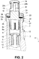
- Figure 3 shows a second embodiment of the safety valve 1 of the invention.
- the safety valve 1 comprises a body 2 which in turn comprises an inlet conduit 3 for the gas, an outlet conduit 4 for the gas communicated with the burner and a magnetic group 7 which is at least partially housed in a housing 5 of the body 2.
- the housing 5 communicates the inlet conduit 3 with the outlet conduit 4 of the body 2. Furthermore, said housing 5 communicates with the outside.
- the magnetic group 7 is known in the state of the art so it will not be described in detail.
- the magnetic group 7, shown in detail in Figures 2 and 3 comprises an electromagnet 8, a shutter 9 adapted for sealing against the body 2 the gas passage towards the outlet conduit 4, a moving frame 10 coupled to the shutter 9 and movable together with the shutter 9 between a safety valve opening position allowing gas passage towards the outlet conduit 4 (and therefore, towards the burner) and a safety valve closing position wherein the shutter 9 closes the gas passage towards the outlet conduit 4 (and therefore, towards the burner), and a spring 11 forcing the shutter 9 together with the moving frame 10 to return to the safety valve closing position when the electromagnet 8 is not energized.
- the shutter 9 is coupled to the moving frame 10 through a rod 12.
- the electromagnet 8 is energized either manually or through a specific power supply source, it is kept energized through a thermocouple (not depicted) as long as said thermocouple detects the presence of flame in the burner.
- a thermocouple not depicted
- the moving frame 10 In said position, the moving frame 10 is in contact with the electromagnet 8 (safety valve opening position) and the shutter 9 does not close the gas passage towards the outlet conduit 4.
- the spring 11 acts on the shutter 9, moving it together with the moving frame 10 to the safety valve closing position, closing gas passage towards the outlet conduit 4.
- the magnetic group 7 comprises a support 15 of the electromagnet 8.
- the support 15 is made of an electrically conductive material, preferably a metallic material.
- the support 15 comprises a housing 16 in which the electromagnet 8 is partially housed and supported.
- the electromagnet 8 comprises a core 8a made of a ferromagnetic material and a winding 8b comprising a first end connected to a grounding terminal and a second end connected to a phase terminal 14 of the magnetic group 7.
- the magnetic group 7 further comprises a casing 13 enclosing therein the electromagnet 8, the moving frame 10 and the support 15 partially.
- the support 15 acts as a grounding terminal, the first end of the winding 8b being fixed to the support 15.
- the second end of the winding 8b in turn at least partially goes through the support 15, being fixed to the phase terminal 14
- the body 2 of the safety valve 1 includes a recess 5b in the housing 5 such that the support 15 is supported on said recess 5b when the magnetic group 7 is housed in the housing 5 of the body 2.
- the safety valve 1 further comprises a bushing 19 electrically connected to the grounding terminal 15 and arranged substantially concentric to the terminal phase 14 of the magnetic group 7.
- the bushing 19, shown in detail in Figure 1 has a cylindrical part 20 and an annular base 21 extending from an end of the cylindrical part 20.
- the bushing 19 is a metallic bushing, preferably a steel bushing. Said bushing 19 is coupled to the support 15.
- said bushing 19 includes protrusions 20b in the cylindrical part 20 extending radially towards the inside of the bushing 19, said protrusions 20b being adapted for guiding the insertion as well as assuring a good connection of the thermocouple (not depicted) with the bushing 19.
- the protrusions 20b are distributed radially equidistant from one another along the perimeter of the bushing 19.
- the bushing 19 is adapted for electrically connecting the grounding terminal of the magnetic group 7 with a grounding terminal of the thermocouple.
- the safety valve 1 further comprises fixing means 22 for fixing the bushing 19 and the magnetic group 7 to the body 2.
- the fixing means 22 comprise a fixing element 23 comprising a cylindrical central part 23a, and an annular flange 24 extending radially towards the inside.
- the base 21 of the bushing 19 is held between the flange 24 of the fixing element 23 and the body 2.
- a free end 25 of the central part 23a is adapted to the outer geometry of the body 2 of the safety valve 1 retaining the fixing element 23 on the body.
- the fixing element 23 is made of a malleable and ductile metal material allowing it to easily adapt to the body 2. Said material is preferably aluminum.
- the fixing element 23 is placed on the bushing 19 such that the annular flange 24 of the fixing element 23 presses on the base 21 of the bushing 19 against the body 2 of the valve 1 and the magnetic group 7, and by means of a suitable tool (such as that shown in Figure 4 ) the free end 25 of the fixing element 23 is crimped to the body 2 of the valve 1 such that the fixing element 23 remains fixed to the body 2 of the valve 1.
- the tool 30 shown in Figure 4 is introduced axially, outside the fixing element 23 such that the geometry thereof forces the free end 25 of the fixing element 23 to fit to the body 2 of the valve 1.
- the safety valve 1 further comprises release means 26 for releasing the magnetic group 7 with respect to the body 2.
- the release means 26 are integrated in the fixing element 23.
- the release means 26 comprise an annular projection between the central part 23a and the annular flange 24 of the fixing element 23. Said annular projection extends orthogonal to the annular flange 24, continuous to said annular flange 24 and to the central part 23a.
- the release means 26 allow the operator to release the magnetic group 7 and/or the bushing 19 from the body 2 easily.
- the operator when the operator has to carry out maintenance actions, such as changing the magnetic group 7 and/or the bushing 19, they press on the release means 26 radially with a suitable tool (such as, for example, suitable pliers) until releasing the free end 25 of the fixing element 23 from the body 2. They then remove the fixing element 23, it being possible to remove the magnetic group 7 and/or the bushing 19 from the body 2.
- a suitable tool such as, for example, suitable pliers
- the fixing element 23 and the bushing 19 are independent parts in the embodiments that have been shown, in other embodiments that are not shown in the drawings, the fixing element 23 and the bushing 19 can form a single part, i.e., both elements can be made of a single part. Taking into account that the bushing 19 is made of a hard metal and the fixing element 23 is made of a ductile and malleable metal, the single part can be made of two different materials to obtain the same effect.
- the safety valve 1 further comprises sealing means 27 and 28 preventing the gas from coming out from the housing 5 of the body 2 towards the outside.
- the sealing means 27 are arranged between a transverse surface 6 of the body 2 and the bushing 19. Said transverse surface demarcates the recess 5b in the housing 5 of the body 2.
- Said sealing means 27 comprise a gasket held between the transverse surface 6 of the body 2 and the base 21 of the bushing 19. The gasket is supported on the transverse surface 6 of the body 2 and on a transverse surface 15b of the support 15. Both transverse surfaces 6 and 15b are aligned with one another when the magnetic group 7 is housed in the housing 5 of the body 2.
- the sealing means 28 comprise an O-ring gasket which is housed in the support 15 and closes against the recess 5b in the housing 5 of the body 2.
- the base 21 of the bushing 19 is supported directly on the respective transverse surfaces 6 and 15b of the body 2 and of the support 15. The rest of the technical features of this second embodiment are the same as those of the first embodiment.
Landscapes
- Engineering & Computer Science (AREA)
- General Engineering & Computer Science (AREA)
- Mechanical Engineering (AREA)
- Chemical & Material Sciences (AREA)
- Combustion & Propulsion (AREA)
- Physics & Mathematics (AREA)
- Electromagnetism (AREA)
- Magnetically Actuated Valves (AREA)
- Feeding And Controlling Fuel (AREA)
Claims (10)
- Sicherheitsventil angepasst an einer Gasverbrennungsanlage, umfassend einen Körper (2), welcher eine Einlassleitung (3) und eine Auslassleitung (4) für das Gas umfasst, eine magnetische Gruppe (7), welche mindestens teilweise in einer Aufnahme (5) des Körpers (2) aufgenommen ist, welche den Gasdurchgang von der Einlassleitung (3) zur Auslassleitung (4) öffnet oder schließt und welche einen Elektromagnet (8) und eine Stütze (15) des genannten Elektromagneten (8) umfasst, eine Buchse (19), welche in der magnetischen Gruppe (7) eingesetzt ist und mit der Stütze (15) gekoppelt ist, und Fixiermittel (22) zum Fixieren der Buchse (19) und der magnetischen Gruppe (7) am Körper (2), wobei die Fixiermittel (22) ein Fixierelement (23) umfassen, welches ein zylindrisches Mittelteil (23a) umfasst, wobei das freie Ende (25) des genannten zylindrischen Mittelteils (23a) an die Geometrie des Körpers (2) angepasst ist, sodass das Fixierelement (23) gegen den Körper (2) gehalten wird, und einen ringförmigen Flansch (24), welcher sich radial nach Innen erstreckt und die Buchse (19) gegen die Stütze (15) hält, wobei das Fixierelement (23) derart auf der Buchse (19) platziert wird, dass der ringförmige Flansch (24) auf eine Basis (21) der Buchse (19) gegen den Körper (2) und die magnetische Gruppe (7) drückt, dadurch gekennzeichnet, dass das freie Ende (25) des Mittelteils (23a) derart am Körper (2) des Ventils (1) gecrimpt ist, dass das Fixierelement (23) am Körper (2) fixiert bleibt.
- Sicherheitsventil nach dem vorhergehenden Anspruch, wobei die Buchse (19) ein zylindrisches Teil (20), welches in Bezug auf den Körper (2) hervorsteht, und eine Basis (21), welche sich von einem Ende des zylindrischen Teils (20) erstreckt und zwischen dem Flansch (24) des Fixierelements (23) und dem Körper (2) gehalten wird, aufweist.
- Sicherheitsventil nach dem vorhergehenden Anspruch, wobei die Buchse (19) Vorsprünge (20b) im zylindrischen Teil (20) beinhaltet, welche sich radial zum Inneren der Buchse (19) erstrecken.
- Sicherheitsventil nach einem der vorhergehenden Ansprüche, umfassend Freigabemittel (26) zum Freigeben der magnetischen Gruppe (7) in Bezug auf den Körper (2), welche im Fixierelement (23) integriert sind.
- Sicherheitsventil nach dem vorhergehenden Anspruch, wobei die Freigabemittel (26) zum Freigeben der magnetischen Gruppe (7) einen ringförmigen Vorsprung zwischen dem Mittelteil (23a) und dem Flansch (24) des Fixierelements (23) umfassen, welcher sich orthogonal zum Flansch (24) erstreckt.
- Sicherheitsventil nach dem vorhergehenden Anspruch, wobei sich der ringförmige Vorsprung durchgängig zum Flansch (24) und zum Mittelteil (23a) erstreckt.
- Sicherheitsventil nach einem der vorhergehenden Ansprüche, umfassend Dichtungsmittel (27), welche zwischen einer Querfläche (6) des Körpers (2) und der Buchse (19) angeordnet sind.
- Sicherheitsventil nach einem der Ansprüche 1 bis 6, umfassend Dichtungsmittel (28), welche in der Stütze (15) aufgenommen sind und gegen eine Aussparung (5b) der Aufnahme (5) des Körpers (2) schließen.
- Sicherheitsventil nach einem der vorhergehenden Ansprüche, wobei das Fixierelement (23) aus einem verformbaren und duktilen metallischen Material hergestellt ist.
- Sicherheitsventil nach einem der Ansprüche 1 bis 8, wobei das Fixierelement (23) und die Buchse (19) in einem einzigen Teil integriert sind.
Applications Claiming Priority (2)
| Application Number | Priority Date | Filing Date | Title |
|---|---|---|---|
| ES201530394U ES1138869Y (es) | 2015-04-08 | 2015-04-08 | Válvula de seguridad adaptada a un aparato de combustión a gas |
| PCT/EP2016/055419 WO2016162173A1 (en) | 2015-04-08 | 2016-03-14 | Safety valve adapted to a gas combustion appliance |
Publications (2)
| Publication Number | Publication Date |
|---|---|
| EP3280955A1 EP3280955A1 (de) | 2018-02-14 |
| EP3280955B1 true EP3280955B1 (de) | 2020-05-06 |
Family
ID=53002871
Family Applications (1)
| Application Number | Title | Priority Date | Filing Date |
|---|---|---|---|
| EP16711186.3A Active EP3280955B1 (de) | 2015-04-08 | 2016-03-14 | Sicherheitsventil angepasst an einer gasverbrennungsanlage |
Country Status (8)
| Country | Link |
|---|---|
| US (1) | US10495308B2 (de) |
| EP (1) | EP3280955B1 (de) |
| CN (1) | CN107429854B (de) |
| AR (1) | AR104187A1 (de) |
| BR (1) | BR112017020600B1 (de) |
| ES (2) | ES1138869Y (de) |
| RU (1) | RU2710638C2 (de) |
| WO (1) | WO2016162173A1 (de) |
Families Citing this family (2)
| Publication number | Priority date | Publication date | Assignee | Title |
|---|---|---|---|---|
| EP3521702B1 (de) * | 2018-02-06 | 2020-07-08 | Orkli, S. Coop. | An ein haushaltsgerät angepasstes gassicherheitsventil |
| CN110260365B (zh) * | 2019-07-11 | 2024-06-07 | 奥可利电子(昆山)有限公司 | 一种双线热电偶和双线圈电磁阀的组装结构 |
Family Cites Families (17)
| Publication number | Priority date | Publication date | Assignee | Title |
|---|---|---|---|---|
| US2503459A (en) * | 1947-03-31 | 1950-04-11 | Milwaukee Gas Specialty Co | Lead connector and cap |
| US2886050A (en) * | 1955-12-21 | 1959-05-12 | Harper Wyman Co | Combined shutoff and safety control valve for burners |
| US2991792A (en) * | 1959-04-21 | 1961-07-11 | Gen Controls Co | Safety reset valve |
| GB8512971D0 (en) * | 1985-05-22 | 1985-06-26 | Concentric Controls Ltd | Thermostatic gas valve |
| DE4201448C2 (de) * | 1992-01-21 | 1995-03-16 | Danfoss As | Tauchanker-Magnetanordnung und Verfahren zu dessen Herstellung |
| ES1023978Y (es) | 1993-03-05 | 1994-06-01 | Orkli S Coop Ltda | Acoplamiento rapido para termopar. |
| ES1024395Y (es) | 1993-03-31 | 1994-05-01 | Orkli S Coop Ltda | Acoplamiento coaxial de termopar al grupo magnetico que controla el paso de gas en quemadores. |
| ES1030940Y (es) * | 1995-04-27 | 1996-08-01 | Vicent Manuel Valls | Conector para el termopar de un quemador de gas. |
| US5785511A (en) * | 1996-07-05 | 1998-07-28 | Shah; Reza H. | Control device for gas supply to main burner and pilot burner of a gas equipment |
| US6609698B1 (en) * | 2000-10-25 | 2003-08-26 | Arichell Technologies, Inc. | Ferromagnetic/fluid valve actuator |
| JP2001349279A (ja) * | 2000-06-07 | 2001-12-21 | Tgk Co Ltd | 可変容量圧縮機用制御弁 |
| ITSV20030013A1 (it) * | 2003-03-31 | 2004-10-01 | Cast Srl | Spinotto di collegamento di una termocoppia ad un gruppo |
| BRPI0414923A (pt) * | 2003-09-30 | 2006-11-07 | Mikuni Kogyo Kk | dispositivo de segurança de queimador a gás |
| US8127791B2 (en) * | 2005-12-21 | 2012-03-06 | Saturn Electronics & Engineering, Inc. | Solenoid operated fluid control valve |
| RU2461757C1 (ru) * | 2011-01-12 | 2012-09-20 | Федеральное Государственное Унитарное Предприятие "Государственный научно-производственный ракетно-космический центр "ЦСКБ-Прогресс" (ФГУП "ГНПРКЦ "ЦСКБ-Прогресс") | Клапан управляемый |
| ES2395536B1 (es) * | 2011-06-15 | 2014-08-08 | Orkli, S.Coop. | Quemador de gas para un aparato doméstico |
| JP5946756B2 (ja) * | 2012-12-11 | 2016-07-06 | 太平洋工業株式会社 | バルブ及びその製造方法 |
-
2015
- 2015-04-08 ES ES201530394U patent/ES1138869Y/es not_active Expired - Fee Related
-
2016
- 2016-03-14 EP EP16711186.3A patent/EP3280955B1/de active Active
- 2016-03-14 BR BR112017020600-5A patent/BR112017020600B1/pt not_active IP Right Cessation
- 2016-03-14 RU RU2017134860A patent/RU2710638C2/ru active
- 2016-03-14 CN CN201680018896.3A patent/CN107429854B/zh not_active Expired - Fee Related
- 2016-03-14 WO PCT/EP2016/055419 patent/WO2016162173A1/en not_active Ceased
- 2016-03-14 ES ES16711186T patent/ES2805238T3/es active Active
- 2016-04-05 AR ARP160100920A patent/AR104187A1/es active IP Right Grant
-
2017
- 2017-10-09 US US15/728,194 patent/US10495308B2/en not_active Expired - Fee Related
Non-Patent Citations (1)
| Title |
|---|
| None * |
Also Published As
| Publication number | Publication date |
|---|---|
| US10495308B2 (en) | 2019-12-03 |
| RU2710638C2 (ru) | 2019-12-30 |
| ES2805238T3 (es) | 2021-02-11 |
| US20180045410A1 (en) | 2018-02-15 |
| ES1138869U (es) | 2015-05-06 |
| AR104187A1 (es) | 2017-07-05 |
| RU2017134860A3 (de) | 2019-07-17 |
| BR112017020600B1 (pt) | 2022-04-12 |
| CN107429854A (zh) | 2017-12-01 |
| RU2017134860A (ru) | 2019-04-04 |
| EP3280955A1 (de) | 2018-02-14 |
| WO2016162173A1 (en) | 2016-10-13 |
| CN107429854B (zh) | 2020-04-10 |
| ES1138869Y (es) | 2015-07-28 |
| BR112017020600A2 (pt) | 2018-07-03 |
Similar Documents
| Publication | Publication Date | Title |
|---|---|---|
| US8851443B2 (en) | Memory alloy-actuated apparatus and methods for making and using the same | |
| US6318703B1 (en) | Electromagnetic valve and process for setting the stroke of an electromagnetic valve | |
| CN105276199B (zh) | 电动阀 | |
| CA2908256C (en) | Valve device | |
| EP3280955B1 (de) | Sicherheitsventil angepasst an einer gasverbrennungsanlage | |
| JP2019060488A (ja) | ダイヤフラムバルブ | |
| JP6308685B2 (ja) | 通電閉型電磁弁の製造方法及び通電閉型電磁弁 | |
| KR20190065313A (ko) | 전자기 액추에이터 | |
| KR20160034805A (ko) | 전자밸브 | |
| US20160009266A1 (en) | Braking fluid control apparatus | |
| EP2040271B1 (de) | Elektromagnetisches Sicherheitsgasventil | |
| EP1988322A2 (de) | Brenner oder andere gasbetriebene Anwendung und speziell eine Kopplungsvorrichtung zur Verbindung eines Brennstoffkanisters mit einem Brennerkopf oder einer anderen Anwendung | |
| KR102244779B1 (ko) | 가스밸브장치 | |
| JP5354387B2 (ja) | 電磁弁 | |
| JP2007092859A (ja) | パイロット型電磁弁 | |
| US7073526B2 (en) | Connecting an electrical cut-off switch in a gas appliance | |
| US4272747A (en) | Solenoid housing | |
| US2458014A (en) | Thermocouple safety pilot switch | |
| JP2014075962A (ja) | 電磁アクチュエータ | |
| CN204387454U (zh) | 适于被装配在燃气器具的安全阀中的磁性安全组 | |
| EP4733638A1 (de) | Tellerventil | |
| US10598407B2 (en) | Gas powered water heater controller and related methods | |
| DE202015004290U1 (de) | Ventil | |
| JP7523249B2 (ja) | 弁装置 | |
| CN114286907A (zh) | 电磁阀 |
Legal Events
| Date | Code | Title | Description |
|---|---|---|---|
| STAA | Information on the status of an ep patent application or granted ep patent |
Free format text: STATUS: THE INTERNATIONAL PUBLICATION HAS BEEN MADE |
|
| PUAI | Public reference made under article 153(3) epc to a published international application that has entered the european phase |
Free format text: ORIGINAL CODE: 0009012 |
|
| STAA | Information on the status of an ep patent application or granted ep patent |
Free format text: STATUS: REQUEST FOR EXAMINATION WAS MADE |
|
| 17P | Request for examination filed |
Effective date: 20171108 |
|
| AK | Designated contracting states |
Kind code of ref document: A1 Designated state(s): AL AT BE BG CH CY CZ DE DK EE ES FI FR GB GR HR HU IE IS IT LI LT LU LV MC MK MT NL NO PL PT RO RS SE SI SK SM TR |
|
| AX | Request for extension of the european patent |
Extension state: BA ME |
|
| RIN1 | Information on inventor provided before grant (corrected) |
Inventor name: PABLO CURTO, MARCOS Inventor name: UNANUE IMAZ, ANDONI Inventor name: ZURIARRAIN BERASATEGI, MIKEL |
|
| DAV | Request for validation of the european patent (deleted) | ||
| DAX | Request for extension of the european patent (deleted) | ||
| GRAP | Despatch of communication of intention to grant a patent |
Free format text: ORIGINAL CODE: EPIDOSNIGR1 |
|
| STAA | Information on the status of an ep patent application or granted ep patent |
Free format text: STATUS: GRANT OF PATENT IS INTENDED |
|
| INTG | Intention to grant announced |
Effective date: 20191126 |
|
| RIN1 | Information on inventor provided before grant (corrected) |
Inventor name: UNANUE IMAZ, ANDONI Inventor name: PABLO CURTO, MARCOS Inventor name: ZURIARRAIN BERASATEGI, MIKEL |
|
| GRAS | Grant fee paid |
Free format text: ORIGINAL CODE: EPIDOSNIGR3 |
|
| GRAA | (expected) grant |
Free format text: ORIGINAL CODE: 0009210 |
|
| STAA | Information on the status of an ep patent application or granted ep patent |
Free format text: STATUS: THE PATENT HAS BEEN GRANTED |
|
| AK | Designated contracting states |
Kind code of ref document: B1 Designated state(s): AL AT BE BG CH CY CZ DE DK EE ES FI FR GB GR HR HU IE IS IT LI LT LU LV MC MK MT NL NO PL PT RO RS SE SI SK SM TR |
|
| REG | Reference to a national code |
Ref country code: GB Ref legal event code: FG4D |
|
| REG | Reference to a national code |
Ref country code: CH Ref legal event code: EP Ref country code: AT Ref legal event code: REF Ref document number: 1267357 Country of ref document: AT Kind code of ref document: T Effective date: 20200515 |
|
| REG | Reference to a national code |
Ref country code: DE Ref legal event code: R096 Ref document number: 602016035690 Country of ref document: DE |
|
| REG | Reference to a national code |
Ref country code: IE Ref legal event code: FG4D |
|
| REG | Reference to a national code |
Ref country code: LT Ref legal event code: MG4D |
|
| REG | Reference to a national code |
Ref country code: NL Ref legal event code: MP Effective date: 20200506 |
|
| PG25 | Lapsed in a contracting state [announced via postgrant information from national office to epo] |
Ref country code: FI Free format text: LAPSE BECAUSE OF FAILURE TO SUBMIT A TRANSLATION OF THE DESCRIPTION OR TO PAY THE FEE WITHIN THE PRESCRIBED TIME-LIMIT Effective date: 20200506 Ref country code: NO Free format text: LAPSE BECAUSE OF FAILURE TO SUBMIT A TRANSLATION OF THE DESCRIPTION OR TO PAY THE FEE WITHIN THE PRESCRIBED TIME-LIMIT Effective date: 20200806 Ref country code: PT Free format text: LAPSE BECAUSE OF FAILURE TO SUBMIT A TRANSLATION OF THE DESCRIPTION OR TO PAY THE FEE WITHIN THE PRESCRIBED TIME-LIMIT Effective date: 20200907 Ref country code: LT Free format text: LAPSE BECAUSE OF FAILURE TO SUBMIT A TRANSLATION OF THE DESCRIPTION OR TO PAY THE FEE WITHIN THE PRESCRIBED TIME-LIMIT Effective date: 20200506 Ref country code: SE Free format text: LAPSE BECAUSE OF FAILURE TO SUBMIT A TRANSLATION OF THE DESCRIPTION OR TO PAY THE FEE WITHIN THE PRESCRIBED TIME-LIMIT Effective date: 20200506 Ref country code: IS Free format text: LAPSE BECAUSE OF FAILURE TO SUBMIT A TRANSLATION OF THE DESCRIPTION OR TO PAY THE FEE WITHIN THE PRESCRIBED TIME-LIMIT Effective date: 20200906 Ref country code: GR Free format text: LAPSE BECAUSE OF FAILURE TO SUBMIT A TRANSLATION OF THE DESCRIPTION OR TO PAY THE FEE WITHIN THE PRESCRIBED TIME-LIMIT Effective date: 20200807 |
|
| PG25 | Lapsed in a contracting state [announced via postgrant information from national office to epo] |
Ref country code: BG Free format text: LAPSE BECAUSE OF FAILURE TO SUBMIT A TRANSLATION OF THE DESCRIPTION OR TO PAY THE FEE WITHIN THE PRESCRIBED TIME-LIMIT Effective date: 20200806 Ref country code: RS Free format text: LAPSE BECAUSE OF FAILURE TO SUBMIT A TRANSLATION OF THE DESCRIPTION OR TO PAY THE FEE WITHIN THE PRESCRIBED TIME-LIMIT Effective date: 20200506 Ref country code: LV Free format text: LAPSE BECAUSE OF FAILURE TO SUBMIT A TRANSLATION OF THE DESCRIPTION OR TO PAY THE FEE WITHIN THE PRESCRIBED TIME-LIMIT Effective date: 20200506 Ref country code: HR Free format text: LAPSE BECAUSE OF FAILURE TO SUBMIT A TRANSLATION OF THE DESCRIPTION OR TO PAY THE FEE WITHIN THE PRESCRIBED TIME-LIMIT Effective date: 20200506 |
|
| REG | Reference to a national code |
Ref country code: AT Ref legal event code: MK05 Ref document number: 1267357 Country of ref document: AT Kind code of ref document: T Effective date: 20200506 |
|
| PG25 | Lapsed in a contracting state [announced via postgrant information from national office to epo] |
Ref country code: NL Free format text: LAPSE BECAUSE OF FAILURE TO SUBMIT A TRANSLATION OF THE DESCRIPTION OR TO PAY THE FEE WITHIN THE PRESCRIBED TIME-LIMIT Effective date: 20200506 Ref country code: AL Free format text: LAPSE BECAUSE OF FAILURE TO SUBMIT A TRANSLATION OF THE DESCRIPTION OR TO PAY THE FEE WITHIN THE PRESCRIBED TIME-LIMIT Effective date: 20200506 |
|
| PG25 | Lapsed in a contracting state [announced via postgrant information from national office to epo] |
Ref country code: SM Free format text: LAPSE BECAUSE OF FAILURE TO SUBMIT A TRANSLATION OF THE DESCRIPTION OR TO PAY THE FEE WITHIN THE PRESCRIBED TIME-LIMIT Effective date: 20200506 Ref country code: EE Free format text: LAPSE BECAUSE OF FAILURE TO SUBMIT A TRANSLATION OF THE DESCRIPTION OR TO PAY THE FEE WITHIN THE PRESCRIBED TIME-LIMIT Effective date: 20200506 Ref country code: CZ Free format text: LAPSE BECAUSE OF FAILURE TO SUBMIT A TRANSLATION OF THE DESCRIPTION OR TO PAY THE FEE WITHIN THE PRESCRIBED TIME-LIMIT Effective date: 20200506 Ref country code: AT Free format text: LAPSE BECAUSE OF FAILURE TO SUBMIT A TRANSLATION OF THE DESCRIPTION OR TO PAY THE FEE WITHIN THE PRESCRIBED TIME-LIMIT Effective date: 20200506 Ref country code: RO Free format text: LAPSE BECAUSE OF FAILURE TO SUBMIT A TRANSLATION OF THE DESCRIPTION OR TO PAY THE FEE WITHIN THE PRESCRIBED TIME-LIMIT Effective date: 20200506 Ref country code: DK Free format text: LAPSE BECAUSE OF FAILURE TO SUBMIT A TRANSLATION OF THE DESCRIPTION OR TO PAY THE FEE WITHIN THE PRESCRIBED TIME-LIMIT Effective date: 20200506 |
|
| REG | Reference to a national code |
Ref country code: DE Ref legal event code: R097 Ref document number: 602016035690 Country of ref document: DE |
|
| REG | Reference to a national code |
Ref country code: ES Ref legal event code: FG2A Ref document number: 2805238 Country of ref document: ES Kind code of ref document: T3 Effective date: 20210211 |
|
| PG25 | Lapsed in a contracting state [announced via postgrant information from national office to epo] |
Ref country code: PL Free format text: LAPSE BECAUSE OF FAILURE TO SUBMIT A TRANSLATION OF THE DESCRIPTION OR TO PAY THE FEE WITHIN THE PRESCRIBED TIME-LIMIT Effective date: 20200506 Ref country code: SK Free format text: LAPSE BECAUSE OF FAILURE TO SUBMIT A TRANSLATION OF THE DESCRIPTION OR TO PAY THE FEE WITHIN THE PRESCRIBED TIME-LIMIT Effective date: 20200506 |
|
| PLBE | No opposition filed within time limit |
Free format text: ORIGINAL CODE: 0009261 |
|
| STAA | Information on the status of an ep patent application or granted ep patent |
Free format text: STATUS: NO OPPOSITION FILED WITHIN TIME LIMIT |
|
| 26N | No opposition filed |
Effective date: 20210209 |
|
| PG25 | Lapsed in a contracting state [announced via postgrant information from national office to epo] |
Ref country code: SI Free format text: LAPSE BECAUSE OF FAILURE TO SUBMIT A TRANSLATION OF THE DESCRIPTION OR TO PAY THE FEE WITHIN THE PRESCRIBED TIME-LIMIT Effective date: 20200506 |
|
| PG25 | Lapsed in a contracting state [announced via postgrant information from national office to epo] |
Ref country code: MC Free format text: LAPSE BECAUSE OF FAILURE TO SUBMIT A TRANSLATION OF THE DESCRIPTION OR TO PAY THE FEE WITHIN THE PRESCRIBED TIME-LIMIT Effective date: 20200506 |
|
| REG | Reference to a national code |
Ref country code: CH Ref legal event code: PL |
|
| REG | Reference to a national code |
Ref country code: BE Ref legal event code: MM Effective date: 20210331 |
|
| PG25 | Lapsed in a contracting state [announced via postgrant information from national office to epo] |
Ref country code: LU Free format text: LAPSE BECAUSE OF NON-PAYMENT OF DUE FEES Effective date: 20210314 Ref country code: LI Free format text: LAPSE BECAUSE OF NON-PAYMENT OF DUE FEES Effective date: 20210331 Ref country code: CH Free format text: LAPSE BECAUSE OF NON-PAYMENT OF DUE FEES Effective date: 20210331 Ref country code: FR Free format text: LAPSE BECAUSE OF NON-PAYMENT OF DUE FEES Effective date: 20210331 Ref country code: IE Free format text: LAPSE BECAUSE OF NON-PAYMENT OF DUE FEES Effective date: 20210314 |
|
| PGFP | Annual fee paid to national office [announced via postgrant information from national office to epo] |
Ref country code: GB Payment date: 20220328 Year of fee payment: 7 Ref country code: DE Payment date: 20220329 Year of fee payment: 7 |
|
| PGFP | Annual fee paid to national office [announced via postgrant information from national office to epo] |
Ref country code: TR Payment date: 20220301 Year of fee payment: 7 Ref country code: IT Payment date: 20220322 Year of fee payment: 7 |
|
| PG25 | Lapsed in a contracting state [announced via postgrant information from national office to epo] |
Ref country code: BE Free format text: LAPSE BECAUSE OF NON-PAYMENT OF DUE FEES Effective date: 20210331 |
|
| PGFP | Annual fee paid to national office [announced via postgrant information from national office to epo] |
Ref country code: ES Payment date: 20220406 Year of fee payment: 7 |
|
| PG25 | Lapsed in a contracting state [announced via postgrant information from national office to epo] |
Ref country code: CY Free format text: LAPSE BECAUSE OF FAILURE TO SUBMIT A TRANSLATION OF THE DESCRIPTION OR TO PAY THE FEE WITHIN THE PRESCRIBED TIME-LIMIT Effective date: 20200506 |
|
| PG25 | Lapsed in a contracting state [announced via postgrant information from national office to epo] |
Ref country code: HU Free format text: LAPSE BECAUSE OF FAILURE TO SUBMIT A TRANSLATION OF THE DESCRIPTION OR TO PAY THE FEE WITHIN THE PRESCRIBED TIME-LIMIT; INVALID AB INITIO Effective date: 20160314 |
|
| REG | Reference to a national code |
Ref country code: DE Ref legal event code: R119 Ref document number: 602016035690 Country of ref document: DE |
|
| GBPC | Gb: european patent ceased through non-payment of renewal fee |
Effective date: 20230314 |
|
| PG25 | Lapsed in a contracting state [announced via postgrant information from national office to epo] |
Ref country code: GB Free format text: LAPSE BECAUSE OF NON-PAYMENT OF DUE FEES Effective date: 20230314 |
|
| PG25 | Lapsed in a contracting state [announced via postgrant information from national office to epo] |
Ref country code: GB Free format text: LAPSE BECAUSE OF NON-PAYMENT OF DUE FEES Effective date: 20230314 Ref country code: DE Free format text: LAPSE BECAUSE OF NON-PAYMENT OF DUE FEES Effective date: 20231003 |
|
| PG25 | Lapsed in a contracting state [announced via postgrant information from national office to epo] |
Ref country code: MK Free format text: LAPSE BECAUSE OF FAILURE TO SUBMIT A TRANSLATION OF THE DESCRIPTION OR TO PAY THE FEE WITHIN THE PRESCRIBED TIME-LIMIT Effective date: 20200506 Ref country code: IT Free format text: LAPSE BECAUSE OF NON-PAYMENT OF DUE FEES Effective date: 20230314 |
|
| REG | Reference to a national code |
Ref country code: ES Ref legal event code: FD2A Effective date: 20240430 |
|
| PG25 | Lapsed in a contracting state [announced via postgrant information from national office to epo] |
Ref country code: ES Free format text: LAPSE BECAUSE OF NON-PAYMENT OF DUE FEES Effective date: 20230315 |
|
| PG25 | Lapsed in a contracting state [announced via postgrant information from national office to epo] |
Ref country code: ES Free format text: LAPSE BECAUSE OF NON-PAYMENT OF DUE FEES Effective date: 20230315 |
|
| PG25 | Lapsed in a contracting state [announced via postgrant information from national office to epo] |
Ref country code: MT Free format text: LAPSE BECAUSE OF FAILURE TO SUBMIT A TRANSLATION OF THE DESCRIPTION OR TO PAY THE FEE WITHIN THE PRESCRIBED TIME-LIMIT Effective date: 20200506 |