EP3280972B1 - Vermessungssystem und verfahren zur optischen vermessung eines objekts - Google Patents
Vermessungssystem und verfahren zur optischen vermessung eines objekts Download PDFInfo
- Publication number
- EP3280972B1 EP3280972B1 EP16721085.5A EP16721085A EP3280972B1 EP 3280972 B1 EP3280972 B1 EP 3280972B1 EP 16721085 A EP16721085 A EP 16721085A EP 3280972 B1 EP3280972 B1 EP 3280972B1
- Authority
- EP
- European Patent Office
- Prior art keywords
- optical attachment
- dental camera
- dimensional
- measuring
- camera
- Prior art date
- Legal status (The legal status is an assumption and is not a legal conclusion. Google has not performed a legal analysis and makes no representation as to the accuracy of the status listed.)
- Active
Links
Images

Classifications
-
- A—HUMAN NECESSITIES
- A61—MEDICAL OR VETERINARY SCIENCE; HYGIENE
- A61B—DIAGNOSIS; SURGERY; IDENTIFICATION
- A61B1/00—Instruments for performing medical examinations of the interior of cavities or tubes of the body by visual or photographical inspection, e.g. endoscopes; Illuminating arrangements therefor
- A61B1/24—Instruments for performing medical examinations of the interior of cavities or tubes of the body by visual or photographical inspection, e.g. endoscopes; Illuminating arrangements therefor for the mouth, i.e. stomatoscopes, e.g. with tongue depressors; Instruments for opening or keeping open the mouth
-
- A—HUMAN NECESSITIES
- A61—MEDICAL OR VETERINARY SCIENCE; HYGIENE
- A61B—DIAGNOSIS; SURGERY; IDENTIFICATION
- A61B5/00—Measuring for diagnostic purposes; Identification of persons
- A61B5/0059—Measuring for diagnostic purposes; Identification of persons using light, e.g. diagnosis by transillumination, diascopy, fluorescence
- A61B5/0082—Measuring for diagnostic purposes; Identification of persons using light, e.g. diagnosis by transillumination, diascopy, fluorescence adapted for particular medical purposes
- A61B5/0088—Measuring for diagnostic purposes; Identification of persons using light, e.g. diagnosis by transillumination, diascopy, fluorescence adapted for particular medical purposes for oral or dental tissue
-
- A—HUMAN NECESSITIES
- A61—MEDICAL OR VETERINARY SCIENCE; HYGIENE
- A61C—DENTISTRY; APPARATUS OR METHODS FOR ORAL OR DENTAL HYGIENE
- A61C9/00—Impression cups, i.e. impression trays; Impression methods
- A61C9/004—Means or methods for taking digitized impressions
- A61C9/0046—Data acquisition means or methods
- A61C9/0053—Optical means or methods, e.g. scanning the teeth by a laser or light beam
-
- A—HUMAN NECESSITIES
- A61—MEDICAL OR VETERINARY SCIENCE; HYGIENE
- A61C—DENTISTRY; APPARATUS OR METHODS FOR ORAL OR DENTAL HYGIENE
- A61C9/00—Impression cups, i.e. impression trays; Impression methods
- A61C9/004—Means or methods for taking digitized impressions
- A61C9/0046—Data acquisition means or methods
- A61C9/0053—Optical means or methods, e.g. scanning the teeth by a laser or light beam
- A61C9/006—Optical means or methods, e.g. scanning the teeth by a laser or light beam projecting one or more stripes or patterns on the teeth
-
- A—HUMAN NECESSITIES
- A61—MEDICAL OR VETERINARY SCIENCE; HYGIENE
- A61C—DENTISTRY; APPARATUS OR METHODS FOR ORAL OR DENTAL HYGIENE
- A61C9/00—Impression cups, i.e. impression trays; Impression methods
- A61C9/004—Means or methods for taking digitized impressions
- A61C9/0046—Data acquisition means or methods
- A61C9/0053—Optical means or methods, e.g. scanning the teeth by a laser or light beam
- A61C9/0066—Depth determination through adaptive focusing
-
- G—PHYSICS
- G01—MEASURING; TESTING
- G01B—MEASURING LENGTH, THICKNESS OR SIMILAR LINEAR DIMENSIONS; MEASURING ANGLES; MEASURING AREAS; MEASURING IRREGULARITIES OF SURFACES OR CONTOURS
- G01B11/00—Measuring arrangements characterised by the use of optical techniques
- G01B11/02—Measuring arrangements characterised by the use of optical techniques for measuring length, width or thickness
- G01B11/022—Measuring arrangements characterised by the use of optical techniques for measuring length, width or thickness by means of tv-camera scanning
-
- G—PHYSICS
- G01—MEASURING; TESTING
- G01B—MEASURING LENGTH, THICKNESS OR SIMILAR LINEAR DIMENSIONS; MEASURING ANGLES; MEASURING AREAS; MEASURING IRREGULARITIES OF SURFACES OR CONTOURS
- G01B11/00—Measuring arrangements characterised by the use of optical techniques
- G01B11/24—Measuring arrangements characterised by the use of optical techniques for measuring contours or curvatures
-
- G—PHYSICS
- G01—MEASURING; TESTING
- G01B—MEASURING LENGTH, THICKNESS OR SIMILAR LINEAR DIMENSIONS; MEASURING ANGLES; MEASURING AREAS; MEASURING IRREGULARITIES OF SURFACES OR CONTOURS
- G01B9/00—Measuring instruments characterised by the use of optical techniques
- G01B9/02—Interferometers
- G01B9/02015—Interferometers characterised by the beam path configuration
- G01B9/02029—Combination with non-interferometric systems, i.e. for measuring the object
- G01B9/0203—With imaging systems
-
- G—PHYSICS
- G02—OPTICS
- G02B—OPTICAL ELEMENTS, SYSTEMS OR APPARATUS
- G02B7/00—Mountings, adjusting means, or light-tight connections, for optical elements
- G02B7/02—Mountings, adjusting means, or light-tight connections, for optical elements for lenses
-
- G—PHYSICS
- G01—MEASURING; TESTING
- G01B—MEASURING LENGTH, THICKNESS OR SIMILAR LINEAR DIMENSIONS; MEASURING ANGLES; MEASURING AREAS; MEASURING IRREGULARITIES OF SURFACES OR CONTOURS
- G01B2210/00—Aspects not specifically covered by any group under G01B, e.g. of wheel alignment, caliper-like sensors
- G01B2210/52—Combining or merging partially overlapping images to an overall image
Definitions
- the invention relates to a method and a measurement system for the optical measurement of an object, comprising a dental camera and an optical attachment.
- DE 102013223894 B3 discloses a surveying system for optically measuring a dental object comprising a dental camera having a light source, a receiving unit and optical components for projecting a dot pattern onto the object to be examined and for relaying the reflected light beams to the receiving unit.
- EP 0438353 A1 discloses an intraoral camera and a laser having instrument, wherein a photo lens is arranged in front of the receiving unit for receiving the whole mouth.
- DE 100 43 749 A1 discloses a dental handpiece having means for imaging and means for directing excitation radiation to a tooth tissue region to be examined, the camera being constructed in two parts from a probe head and a camera module.
- the camera can be equipped with different imaging properties and thus to the be adapted to the respective field of application.
- a transfer device in the form of a prism is used.
- a disadvantage of this dental camera is that the dental camera can only be used for measuring the teeth.
- the object of the present invention is to provide a surveying system for optical measurement, which can accommodate not only teeth but also larger objects.
- the invention according to independent claim 1 relates to a surveying system for optical measurement of an object, comprising a dental camera and an optical attachment.
- the optical attachment comprises at least one lens which is shaped and arranged such that the optical attachment has a negative focal length, so that a measurement field or a measurement volume of the dental camera is enlarged by the optical attachment.
- the dental camera may be any hand-held dental camera based on a two-dimensional or even a three-dimensional surveying method.
- the object may be the patient's teeth and the patient's face.
- the optical attachment may be provided with attachment means for attachment to a conventional dental camera.
- the fastening means may for example correspond to the fastening means of an already known mirror sleeve.
- the attachment means may for example comprise a latching mechanism and a leaf spring, so that the attachment engages when placed on the dental camera and thus fixed in position relative to the dental camera.
- the optical attachment can therefore comprise a single lens or else a lens system composed of a plurality of optical lenses, which are arranged relative to one another and shaped such that the optical attachment has a negative focal length and widens the measurement volume.
- the optical attachment may for example consist of a plano-convex lens and a convex-plan lens or of a concave-convex lens and a convex-concave lens.
- the measuring field is the area within which the dental camera measures the object. In a three-dimensional optical dental camera, a measurement volume of the object is measured. The optical attachment significantly enlarges this measurement field in a two-dimensional camera or a measurement volume in a three-dimensional camera, so that larger objects can be measured.
- An advantage of the surveying system is that a conventional dental camera can be used not only for measuring the teeth, but also for surveying larger objects, such as the face of a patient or a portion of the face, through the optical attachment.
- the dental camera can be based on a two-dimensional measuring method or on a three-dimensional measuring method.
- the optical attachment can be used both for two-dimensional dental cameras and for three-dimensional dental cameras.
- the dental camera on a two-dimensional video recording method a three-dimensional Triangulation measuring method, a three-dimensional confocal surveying method or a Betterlichtinterferometriever horrungsvon are based.
- the three-dimensional triangulation measurement method may be, for example, the known fringe projection method in which a pattern of light and dark stripes is projected onto the measurement project. The projected fringe pattern is then captured at a known viewing angle for projection by the dental camera. Using a so-called phase shift method, a projection coordinate representing the position of the strip in the pattern is determined. With a known triangulation angle between an illumination beam and an observation beam, the 3D spatial coordinate of the respective measurement point of the object can be determined. In this way, the spatial coordinate is determined for each measuring point of the object and a three-dimensional image of the surface of the object is calculated.
- the surface of the dental object is scanned stepwise, whereby a focal plane is shifted stepwise.
- the light outside the focal plane is suppressed as much as possible by means of a pinhole. From the measured image data of the individual steps of different focal planes, a three-dimensional image of the measured object can then be calculated.
- the two-dimensional video recording method is a known surveying method in which a sequence of two-dimensional images of the object is generated.
- a light of short coherence length is used so that colored interference occurs when the path length in the reference or object beam are almost equal.
- the interference pattern is changed, so that based on the interference pattern, the distance to the surface of the object can be determined.
- the dental camera can also be based on a surveying method which is a combination of a two-dimensional video recording method and a three-dimensional triangulation method, wherein the three-dimensional recording from the triangulation measurement method is superimposed on the two-dimensional color video recording, so that a three-dimensional color photograph is produced.
- a surveying method which is a combination of a two-dimensional video recording method and a three-dimensional triangulation method, wherein the three-dimensional recording from the triangulation measurement method is superimposed on the two-dimensional color video recording, so that a three-dimensional color photograph is produced.
- the optical attachment can be detachably connected to the dental camera by means of a connection means.
- the attachment means of the optical attachment to the camera are designed so that the optical attachment is arranged in a fixed position and orientation relative to the camera.
- the connecting means may be, for example, a screw connection.
- the measurement field or the measurement volume of the dental camera can be increased by a magnification factor that is at least 5.
- a typical measuring volume of a dental camera in the form of a cube having an edge length of between 15 mm and 20 mm can thus be widened to an enlarged measuring volume which, for example, has an edge length of at least 30 mm. That must have volume as well significantly larger edge length, such as have at least 100 mm.
- the edge length of the measurement volume should be selected so that relevant facial areas such as the mouth, nose and / or eyes can be registered.
- the optical attachment may additionally comprise a beam deflector, which deflects an illumination beam and an observation beam of the dental camera to the object.
- the beam deflector can be for example a mirror or a prism, in which way the measuring direction of the recording can run perpendicular to the longitudinal direction of the camera.
- the optical attachment may comprise a plurality of lenses which are shaped and arranged with respect to one another such that the optical attachment has a negative focal length.
- multiple optical lenses are used to generate the negative focal length.
- the measurement volume of the three-dimensional dental camera in the form of a cube with an edge length between 10 mm and 20 mm can be increased to an enlarged measurement volume with an edge length of at least 30 mm by means of the optical attachment.
- a partial area of the face can be measured by means of the camera with the attachment.
- the invention according to independent claim 9 further relates to a method for measuring an object by means of a dental camera with a detachable optical attachment.
- the optical attachment has a negative focal length, so that through the optical Attachment a measuring field or a measuring volume of the dental camera is enlarged.
- the present method therefore makes it possible to measure a larger measuring field by means of a conventional dental camera with the novel optical attachment.
- the dental camera can be based on a two-dimensional measuring method or on a three-dimensional measuring method.
- the present method can also be applied to a two-dimensional or a three-dimensional dental camera.
- the dental camera can be based on a two-dimensional video recording method, a three-dimensional triangulation measuring method, a three-dimensional confocal measuring method or a white-light interferometric measuring method.
- the method can be used for a dental camera based on the aforementioned surveying method.
- the measuring field or the measuring volume of the dental camera can be increased by a magnification factor which is at least 5 by means of the optical attachment.
- the measuring field is significantly increased.
- the teeth of a patient can be measured in a first step by means of the dental camera without the optical attachment and a first image of the teeth is generated, wherein in a second step by means of the dental camera with the optical attachment with the enlarged measurement field or measurement volume at least a part a face of the patient is measured and a second image of the face is generated, wherein subsequently the first image of the teeth and the second image of the face are registered to a total recording.
- the tooth situation can be measured by means of the dental camera without an attachment, and at least a partial area of the face by means of the camera with the attachment.
- the measured partial area of the face can include, for example, characteristic areas such as nostrils, the course of the chin, and at the same time also the teeth, in particular the cusp tips of the canines.
- the recorded teeth can be replaced by the more precise recording of the teeth using the camera without attachment at registration.
- Such a receptacle which comprises both a part of the face and the teeth, allows the dental technician or the dentist to plan the treatment, taking into account the shape of the face, the width of the nostrils or the course of the chin. When planning dental prostheses, this information can be used.
- the tooth replacement parts may be designed so that the distance between the cusp tips of the two canines coincides with the nasal wing width to mimic an aesthetic visual impression of natural teeth.
- the Fig. 1 shows a surveying system 1 for optical measurement of an object 2, which may be a face of the patient 3 and / or the teeth 4 of a patient.
- the surveying system 1 comprises a conventional dental camera 5 and an optical attachment 6, which has a first plano-convex lens 7 and a second convex-lens 8.
- the two lenses 7 and 8 are shaped and arranged relative to the camera 5 so that the optical attachment 6 has a negative focal length.
- a measurement volume 9 of the dental camera 5 is relatively small and, for example, can have an edge length 10 between 10 mm and 20 mm for a cube-shaped form.
- this measurement volume 9 is enlarged to an enlarged measurement volume 11 having an edge length 12 of at least 100 mm.
- the first illumination beams 13 of the dental camera 5 without the optical attachment 6 are indicated by the dashed lines.
- the second illumination beams 14 of the dental Camera 5 with the optical attachment 6 define the limits of the enlarged measurement volume 11.
- the surveying system 1 can thus be used for a method in which the teeth 4 are measured in the first step by means of the camera 5 without the optical attachment 6 and then in the second step by means of the same camera 5 with the optical attachment 6 a portion of the face. 3 of the patient is measured. The two recordings can then be registered to each other.
- the dental camera 5 may be based on a three-dimensional triangulation method or on a confocal survey method.
- the Fig. 2 shows a sketch to illustrate the beam paths of the illumination beams 14 of the dental camera 5 without the optical attachment 6.
- the design of the dental camera 5 can be designed arbitrarily.
- the dental camera 5 may comprise a mirror sleeve, which in Fig. 1 is shown, which deflects the illumination beams 14 perpendicular to the longitudinal axis of the dental camera 5.
- the dental camera 5 can also be used without a mirror sleeve, as in Fig. 2 is shown.
- the illumination beams 14 are emitted in the direction of a longitudinal axis 20 of the dental camera 5.
- a small measurement volume 9 is shown by the dashed line, which only measures a partial area of a tooth.
- the Fig. 3 shows a sketch of the camera 5 Fig. 2 with the optical attachment 6 comprising a first lens 7 and a second lens 8.
- the optical attachment 6 is thus in the beam path of the illumination beams 14 of the widened measuring field 11 in addition to the lens 30 of the dental camera 5 consisting of a first lens 31 and a second lens 32nd arranged.
- the measuring volume 9 of the dental camera 5 is increased to the expanded measuring volume 11, wherein not only the edge length 10 but also a depth measuring range 33 is increased.
- the enlargement of the depth measurement range is based on that the triangulation angle is reduced accordingly due to the longer focus.
- the longer focus also increases the depth range.
- Fig. 3 is shown schematically how the illumination beams 14 are widened and thus the focus points 34 are further apart than in Fig. 1 ,
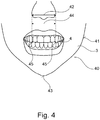
- the Fig. 4 shows a receptacle 40 of a portion of the face 3 and the teeth 4 by means of the camera 5 with the optical attachment 6 from Fig. 1 , To improve the accuracy of the more precise recording of the teeth can be registered by means of the camera 5 without attachment 6 with the recording of the face 3. Because the inclusion of the teeth 4 by means of the camera 5 without attachment 6 has a higher resolution.
- the receptacle 40 of the face 3 allows the dental technician or the dentist to carry out therapy planning taking into account a face shape 41, a nasal wing width 42, a profile of the chin 43 and / or a distance 44 from cusp tips 45 of the canines. In the case shown off Fig. 4 the nostril width 42 coincides with the distance 44. This is natural for most people. So the planning of dental restorations also takes into account the nostril width 42 in order to imitate natural teeth.
Landscapes
- Health & Medical Sciences (AREA)
- Life Sciences & Earth Sciences (AREA)
- Physics & Mathematics (AREA)
- Oral & Maxillofacial Surgery (AREA)
- Dentistry (AREA)
- Animal Behavior & Ethology (AREA)
- General Health & Medical Sciences (AREA)
- Public Health (AREA)
- Veterinary Medicine (AREA)
- Optics & Photonics (AREA)
- Epidemiology (AREA)
- Surgery (AREA)
- General Physics & Mathematics (AREA)
- Biophysics (AREA)
- Engineering & Computer Science (AREA)
- Biomedical Technology (AREA)
- Heart & Thoracic Surgery (AREA)
- Medical Informatics (AREA)
- Molecular Biology (AREA)
- Pathology (AREA)
- Audiology, Speech & Language Pathology (AREA)
- Nuclear Medicine, Radiotherapy & Molecular Imaging (AREA)
- Radiology & Medical Imaging (AREA)
- Dental Tools And Instruments Or Auxiliary Dental Instruments (AREA)
- Length Measuring Devices By Optical Means (AREA)
Description
- Die Erfindung betrifft ein Verfahren und ein Vermessungssystem zur optischen Vermessung eines Objekts, umfassend eine dentale Kamera und einen optischen Aufsatz.
- Aus dem Stand der Technik sind mehrere Verfahren und Vermessungsvorrichtungen zur optischen Vermessung eines dentalen Objekts bekannt.
-
DE 102013223894 B3 offenbart ein Vermessungssystem zur optischen Vermessung eines dentalen Objekts, umfassend eine dentale Kamera, die eine Lichtquelle, eine Aufnahmeeinheit und optische Komponenten zur Projektion eines Punktmusters auf das zu untersuchende Objekt und zur Weiterleitung der reflektierten Lichtstrahlen auf die Aufnahmeeinheit aufweist. -
EP 0438353 A1 offenbart eine intraorale Kamera und ein Laser aufweisendes Instrument, wobei eine Fotolinse vor der Aufnahmeeinheit zur Aufnahme des ganzen Mundes angeordnet wird. -
DE 100 43 749 A1 offenbart ein zahnmedizinisches Handstück mit Mitteln zur Bildaufnahme sowie Mittel, um eine Anregungsstrahlung auf einen zu untersuchenden Zahngewebebereich zu richten, wobei die Kamera zweiteilig aus einem Sondenkopf und einem Kameramodul aufgebaut ist. Durch Verwendung verschiedener Objekthülsen mit unterschiedlichen optischen Eigenschaften kann die Kamera mit unterschiedlichen Abbildungseigenschaften ausgestattet und somit an das jeweilige Anwendungsgebiet angepasst werden. Zur Übertragung des Bildes innerhalb des Aufsatzes wird eine Umlegungsvorrichtung in Form eines Prismas verwendet.
Ein Nachteil dieser dentalen Kamera besteht darin, dass die dentale Kamera lediglich zur Vermessung der Zähne verwendet werden kann.
Die Aufgabe der vorliegenden Erfindung besteht daher darin, ein Vermessungssystem zur optischen Vermessung bereit zu stellen, das nicht nur Zähne sondern auch größere Objekte aufnehmen kann. - Die Erfindung gemäß dem unabhängigen Anspruch 1 betrifft ein Vermessungssystem zur optischen Vermessung eines Objekts, umfassend eine dentale Kamera und einen optischen Aufsatz. Der optische Aufsatz umfasst dabei mindestens eine Linse, die so geformt und angeordnet ist, dass der optische Aufsatz eine negative Brennweite aufweist, so dass durch den optischen Aufsatz ein Messfeld oder ein Messvolumen der dentalen Kamera vergrößert wird. Die dentale Kamera kann eine beliebige handgehaltene dentale Kamera sein, die auf einem zweidimensionalen oder auch auf einem dreidimensionalen Vermessungsverfahren beruht. Das Objekt können die Zähne des Patienten und das Gesicht des Patienten sein. Der optische Aufsatz kann mit Befestigungsmitteln ausgestattet sein, um an einer herkömmlichen dentalen Kamera befestigt zu werden. Die Befestigungsmittel können beispielsweise den Befestigungsmitteln einer bereits bekannten Spiegelhülse entsprechen.
Die Befestigungsmittel können beispielsweise einen Rastmechanismus und eine Blattfeder umfassen, so dass der Aufsatz beim Aufsetzen auf die dentale Kamera einrastet und damit in seiner Position relativ zur dentalen Kamera fixiert wird. - Der optische Aufsatz kann also eine einzelne Linse oder auch ein Linsensystem aus mehreren optischen Linsen umfassen, die zueinander so angeordnet sind und so geformt sind, dass der optische Aufsatz eine negative Brennweite aufweist und das Messvolumen aufweitet. Der optische Aufsatz kann beispielsweise aus einer plankonvexen Linse und einer konvexplanen Linse oder aus einer konkav konvexen Linse und einer konvex konkaven Linse bestehen. Das Messfeld ist der Bereich innerhalb dessen die dentale Kamera das Objekt vermisst. Bei einer dreidimensionalen optischen dentalen Kamera wird ein Messvolumen des Objekts vermessen. Durch den optischen Aufsatz wird dieses Messfeld bei einer zweidimensionalen Kamera oder ein Messvolumen bei einer dreidimensionalen Kamera deutlich vergrößert, sodass größere Objekte vermessen werden können.
- Ein Vorteil des Vermessungssystems besteht darin, dass eine herkömmliche dentale Kamera nicht nur zur Vermessung der Zähne, sondern durch den optischen Aufsatz auch zur Vermessung größerer Objekte, wie des Gesichtes eines Patienten oder ein Teilbereich des Gesichtes verwendet werden kann.
- Vorteilhafterweise kann die dentale Kamera auf einem zweidimensionalen Vermessungsverfahren oder auf einem dreidimensionalen Vermessungsverfahren beruhen.
- Dadurch kann der optische Aufsatz sowohl für zweidimensionale dentale Kameras als auch für dreidimensionale dentale Kameras verwendet werden.
- Vorteilhafterweise kann die dentale Kamera auf einem zweidimensionalen Videoaufnahmeverfahren, einem dreidimensionalen Triangulationsmessverfahren, einem dreidimensionalen konfokalen Vermessungsverfahren oder einem Weißlichtinterferometrievermessungsverfahren beruhen.
- Das dreidimensionale Triangulationsmessverfahren kann beispielsweise das bekannte Streifenprojektionsverfahren sein, bei dem ein Muster aus hellen und dunklen Streifen auf das Messprojekt projiziert wird. Das projizierte Streifenmuster wird dann unter einem bekannten Blickwinkel zur Projektion mittels der dentalen Kamera aufgenommen. Unter Verwendung eines sogenannten Phasenschiebeverfahrens wird eine Projektionskoordinate bestimmt, die die Position des Streifens im Muster wiedergibt. Bei einem bekannten Triangulationswinkel zwischen einem Beleuchtungsstrahl und einem Beobachtungsstrahl kann die 3D-Raumkoordinate des jeweiligen Messpunktes des Objekts ermittelt werden. Auf diese Weise wird für jeden Messpunkt des Objekts die Raumkoordinate ermittelt und ein dreidimensionales Bild der Oberfläche des Objekts berechnet.
- Bei den dreidimensionalen konfokalen Vermessungsverfahren wird die Oberfläche des dentalen Objekts schrittweise abgetastet, wobei eine Fokalebene schrittweise verschoben wird. Das Licht außerhalb der Fokalebene wird mittels einer Lochblende möglichst ausgeblendet. Aus den gemessenen Bilddaten der einzelnen Schritte unterschiedlicher Fokalebenen kann anschließend ein dreidimensionales Bild des vermessenen Objekts berechnet werden.
- Das zweidimensionale Videoaufnahmeverfahren ist ein bekanntes Vermessungsverfahren, bei dem eine Abfolge von zweidimensionalen Bildern des Objekts erzeugt wird.
- Bei der Weißlichtinterferometrie wird ein Licht geringer Kohärenzlänge verwendet, so dass farbige Interferenzen entstehen, wenn die Weglänge im Referenz- oder Objektstrahl nahezu gleich sind. Beim Verändern der Weglänge wird das Interferenzmuster verändert, so dass anhand des Interferenzmusters der Abstand zur Oberfläche des Objekts bestimmt werden kann.
- Die dentale Kamera kann auch auf einem Vermessungsverfahren beruhen, das eine Kombination aus einem zweidimensionalen Videoaufnahmeverfahren und einem dreidimensionalen Triangulationsverfahren darstellt, wobei die dreidimensionale Aufnahme aus dem Triangulationsmessverfahren mit der farbigen zweidimensionalen Videoaufnahme überlagert wird, so dass eine dreidimensionale farbige Aufnahme erzeugt wird.
- Vorteilhafterweise kann der optische Aufsatz mit der dentalen Kamera trennbar mittels eines Verbindungsmittels verbunden sein.
- Dadurch kann der Benutzer kleinere Objekte, wie Zähne, mittels der Kamera ohne Aufsatz und größere Objekte, wie Teilbereiche des Gesichtes, mittels der Kamera mit dem Aufsatz vermessen. Die Befestigungsmittel des optischen Aufsatzes an der Kamera sind so ausgestaltet, dass der optische Aufsatz in einer fest definierten Lage und Ausrichtung relativ zur Kamera angeordnet wird. Die Verbindungsmittel können beispielsweise eine Schraubverbindung sein.
- Vorteilhafterweise kann mittels des optischen Aufsatzes das Messfeld oder das Messvolumen der dentalen Kamera um einen Vergrößerungsfaktor vergrößert sein, der mindestens 5 beträgt.
- Dadurch kann also ein typisches Messvolumen einer dentalen Kamera in der Form eines Würfels mit einer Kantenlänge zwischen 15 mm und 20 mm auf ein vergrößertes Messvolumen aufgeweitet werden, das beispielsweise eine Kantenlänge von mindestens 30 mm aufweist. Das muss Volumen kann auch eine deutlich größere Kantenlänge, wie beispielsweise von mindestens 100 mm aufweisen. Die Kantenlänge des Messvolumens sollte so gewählt werden, dass relevante Gesichtspartien, wie der Mund, die Nase und/oder die Augen registriert werden können.
Vorteilhafterweise kann der optische Aufsatz zusätzlich einen Strahlumlenker umfassen, der einen Beleuchtungsstrahl und einen Beobachtungsstrahl der dentalen Kamera zum Objekt umlenkt.
Der Strahlumlenker kann beispielsweise ein Spiegel oder ein Prisma sein, wobei auf diese Weise die Vermessungsrichtung der Aufnahme senkrecht zur Längsrichtung der Kamera verlaufen kann. Insbesondere bei der Vermessung der Zähne ist dies vorteilhaft.
Vorteilhafterweise kann der optische Aufsatz mehrere Linsen umfassen, die so geformt sind und zueinander so angeordnet sind, dass der optische Aufsatz eine negative Brennweite aufweist.
Dadurch werden also mehrere optische Linsen verwendet, um die negative Brennweite zu erzeugen.
Vorteilhafterweise kann mittels des optischen Aufsatzes das Messvolumen der dreidimensionalen dentalen Kamera in Form eines Würfels mit einer Kantenlänge zwischen 10 mm und 20 mm auf ein vergrößertes Messvolumen mit einer Kantenlänge von mindestens 30 mm vergrößert werden.
Dadurch kann mittels der Kamera mit dem Aufsatz ein Teilbereich des Gesichtes vermessen werden.
Die Erfindung gemäß dem unabhängigen Anspruch 9 betrifft weiterhin ein Verfahren zur Vermessung eines Objekts mittels einer dentalen Kamera mit einem ) abtrennbaren optischen Aufsatz. Der optische Aufsatz weist dabei eine negative Brennweite auf, so dass durch den optischen Aufsatz ein Messfeld oder ein Messvolumen der dentalen Kamera vergrößert wird. - Das vorliegende Verfahren ermöglicht also mittels einer herkömmlichen dentalen Kamera mit dem neuartigen optischen Aufsatz ein größeres Messfeld zu vermessen.
- Vorteilhafterweise kann die dentale Kamera auf einem zweidimensionalen Vermessungsverfahren oder auf einem dreidimensionalen Vermessungsverfahren beruhen.
- Dadurch kann das vorliegende Verfahren auch auf eine zweidimensionale oder eine dreidimensionale dentale Kamera angewendet werden.
- Vorteilhafterweise kann die dentale Kamera auf einem zweidimensionalen Videoaufnahmeverfahren, einem dreidimensionalen Triangulationsmessverfahren, einem dreidimensionalen konfokalen Vermessungsverfahren oder einem Weißlichtinterferometrievermessungsverfahren beruhen.
- Dadurch kann das Verfahren für eine dentale Kamera verwendet werden, die auf den genannten Vermessungsverfahren beruht.
- Vorteilhafterweise kann mittels des optischen Aufsatzes das Messfeld oder das Messvolumen der dentalen Kamera um einen Vergrößerungsfaktor vergrößert werden, der mindestens 5 beträgt.
- Dadurch wird also das Messfeld deutlich vergrößert.
- Vorteilhafterweise können in einem ersten Schritt mittels der dentalen Kamera ohne den optischen Aufsatz die Zähne eines Patienten vermessen werden und eine erste Aufnahme der Zähne erzeugt wird, wobei in einem zweiten Schritt mittels der dentalen Kamera mit dem optischen Aufsatz mit dem vergrößerten Messfeld bzw. Messvolumen zumindest ein Teil eines Gesichtes des Patienten vermessen wird und eine zweite Aufnahme des Gesichtes erzeugt wird, wobei anschließend die erste Aufnahme der Zähne und die zweite Aufnahme des Gesichtes zu einer Gesamtaufnahme registriert werden.
- Dadurch kann mittels der dentalen Kamera ohne Aufsatz die Zahnsituation und mittels der Kamera mit dem Aufsatz zumindest ein Teilbereich des Gesichtes vermessen werden. Der vermessene Teilbereich des Gesichtes kann dabei beispielsweise charakteristische Bereiche, wie Nasenflügel, den Verlauf des Kinns, sowie gleichzeitig auch die Zähne, insbesondere die Höckerspitzen der Eckzähne umfassen. Die aufgenommenen Zähne können durch die präzisere Aufnahme der Zähne mittels der Kamera ohne Aufsatz bei der Registrierung ersetzt werden. Eine solche Aufnahme die sowohl einen Teil des Gesichtes als auch die Zähne umfasst, ermöglicht dem Zahntechniker oder dem Zahnarzt eine Therapieplanung unter Berücksichtigung der Gesichtsform, der Nasenflügelbreite oder dem Verlauf des Kinns. Bei der Planung von Zahnersatzteilen können also diese Informationen verwendet werden. Beispielsweise können die Zahnersatzteile so geplant werden, dass der Abstand zwischen den Höckerspitzen der beiden Eckzähne mit der Nasenflügelbreite übereinstimmt, um einen ästhetischen optischen Eindruck von natürlichen Zähnen nachzuahmen.
- Die Erfindung wird anhand der Zeichnungen erläutert. Es zeigt, die
- Fig. 1
- ein Vermessungssystem umfassend eine dentale Kamera und einen optischen Aufsatz; die
- Fig. 2
- eine Skizze zur Verdeutlichung der Strahlengänge der Beobachtungsstrahlen der dentalen Kamera ohne den optischen Aufsatz; die
- Fig. 3
- eine Skizze zur Verdeutlichung der Strahlengänge der Beobachtungsstrahlen der dentalen Kamera mit dem optischen Aufsatz; die
- Fig. 4
- zeigt eine Aufnahme eines Teilbereichs des Gesichtes und der Zähne mittels der Kamera mit dem optischen Aufsatz.
- Die
Fig. 1 zeigt ein Vermessungssystem 1 zur optischen Vermessung eines Objekts 2, das ein Gesicht des Patienten 3 und/oder die Zähne 4 eines Patienten sein können. Das Vermessungssystem 1 umfasst eine herkömmliche dentale Kamera 5 und einen optischen Aufsatz 6, der eine erste plankonvexe Linse 7 und eine zweite konvexplane Linse 8 aufweist. Die beiden Linsen 7 und 8 sind so geformt und relativ zur Kamera 5 so angeordnet, dass der optische Aufsatz 6 eine negative Brennweite aufweist. Mittels der Kamera 5 ohne den optischen Aufsatz 6 werden kleine Objekte, wie die Zähne 4 vermessen, wobei ein Messvolumen 9 der dentalen Kamera 5 relativ klein ist und bei einer würfelförmigen Form beispielsweise eine Kantenlänge 10 zwischen 10 mm und 20 mm aufweisen kann. Durch den optischen Aufsatz 6 wird dieses Messvolumen 9 auf ein vergrößertes Messvolumen 11 mit einer Kantenlänge 12 von mindestens 100 mm vergrößert. Die ersten Beleuchtungsstrahlen 13 der dentalen Kamera 5 ohne den optischen Aufsatz 6 sind durch die gestrichelten Linien angedeutet. Die zweiten Beleuchtungsstrahlen 14 der dentalen Kamera 5 mit dem optischen Aufsatz 6 definieren die Grenzen des vergrößerten Messvolumens 11. - Das Vermessungssystem 1 kann also für ein Verfahren verwendet werden, bei dem im ersten Schritt mittels der Kamera 5 ohne den optischen Aufsatz 6 die Zähne 4 vermessen werden und anschließend im zweiten Schritt mittels der derselben Kamera 5 mit dem optischen Aufsatz 6 ein Teilbereich des Gesichtes 3 des Patienten vermessen wird. Die beiden Aufnahmen können dann anschließend zueinander registriert werden. Die dentale Kamera 5 kann auf einem dreidimensionalen Triangulationsverfahren oder auf einem konfokalen Vermessungsverfahren beruhen.
- Die
Fig. 2 zeigt eine Skizze zur Verdeutlichung der Strahlengänge der Beleuchtungsstrahlen 14 der dentalen Kamera 5 ohne den optischen Aufsatz 6. Die Bauform der dentalen Kamera 5 kann beliebig gestaltet sein. Dabei kann die dentale Kamera 5 eine Spiegelhülse aufweisen, die inFig. 1 dargestellt ist, die die Beleuchtungsstrahlen 14 senkrecht zur Längsachse der dentalen Kamera 5 umlenkt. Die dentale Kamera 5 kann jedoch auch ohne Spiegelhülse verwendet werden, wie inFig. 2 dargestellt ist. Dabei werden die Beleuchtungsstrahlen 14 in die Richtung einer Längsachse 20 der dentalen Kamera 5 abgestrahlt. InFig. 2 ist ein kleines Messvolumen 9 durch die gestrichelte Linie dargestellt, das lediglich einen Teilbereich eines Zahns vermisst. - Die
Fig. 3 zeigt eine Skizze der Kamera 5 ausFig. 2 mit dem optischen Aufsatz 6 umfassend eine erste Linse 7 und eine zweite Linse 8. Der optische Aufsatz 6 wird also im Strahlengang der Beleuchtungsstrahlen 14 des aufgeweiteten Messfeldes 11 zusätzlich zum Objektiv 30 der dentalen Kamera 5 bestehend aus einer ersten Linse 31 und einer zweiten Linse 32 angeordnet. Dadurch wird also das Messvolumen 9 der dentalen Kamera 5 bis zum aufgeweiteten Messvolumen 11 vergrößert, wobei nicht nur die Kantenlänge 10 sondern auch ein Tiefenmessbereich 33 vergrößert wird. Bei dem Triangulationsmessverfahren beruht die Vergrößerung des Tiefenmessbereichs darauf, dass der Triangulationswinkel aufgrund des längeren Fokus entsprechend verkleinert wird. Beim konfokalen Vermessungsverfahren führt der längere Fokus ebenfalls zur Vergrößerung des Tiefenmessbereichs. InFig. 3 ist schematisch dargestellt, wie die Beleuchtungsstrahlen 14 aufgeweitet werden und dadurch auch die Fokuspunkte 34 weiter auseinander liegen, als inFig. 1 . - Die
Fig. 4 zeigt eine Aufnahme 40 eines Teilbereichs des Gesichtes 3 und der Zähne 4 mittels der Kamera 5 mit dem optischen Aufsatz 6 ausFig. 1 . Zur Verbesserung der Genauigkeit kann die präzisere Aufnahme der Zähne mittels der Kamera 5 ohne Aufsatz 6 mit der Aufnahme des Gesichtes 3 registriert werden. Denn die Aufnahme der Zähne 4 mittels der Kamera 5 ohne Aufsatz 6 weist eine höhere Auflösung auf. Die Aufnahme 40 des Gesichtes 3 ermöglicht es dem Zahntechniker oder dem Zahnarzt eine Therapieplanung unter Berücksichtigung einer Gesichtsform 41, einer Nasenflügelbreite 42, einem Verlauf des Kinns 43 und/ oder einem Abstand 44 von Höckerspitzen 45 der Eckzähne durchzuführen. Im dargestellten Fall ausFig. 4 stimmt die Nasenflügelbreite 42 mit dem Abstand 44 überein. Dies entspricht einer natürlichen Gegebenheit bei den meisten Menschen. Sei der Planung von Zahnrestaurationen wird also auch die Nasenflügelbreite 42 berücksichtigt, um natürliche Zähne nachzuahmen. -
- 1
- Vermessungssystem
- 2
- Objekt
- 3
- Patient / Gesicht des Patienten
- 4
- Zähne
- 5
- dentale Kamera
- 6
- optischer Aufsatz
- 7
- erste Linse
- 8
- zweite Linse
- 9
- Messvolumen
- 10
- Kantenlänge
- 11
- vergrößertes Messvolumen
- 12
- Kantenlänge
- 13
- erste Beleuchtungsstrahlen
- 14
- zweite Beobachtungsstrahlen
- 20
- Längsachse
- 30
- Objektiv
- 31
- erste Linse
- 32
- zweite Linse
- 33
- Tiefenmessbereich
- 34
- Fokuspunkte
- 40
- Aufnahme
- 41
- Gesichtsform
- 42
- Nasenflügelbreite
- 43
- Kinn
- 44
- Abstand
- 45
- Höckerspitzen
Claims (13)
- Vermessungssystem (1) zur optischen Vermessung eines Objekts (2), umfassend eine dentale Kamera (5) und einen optischen Aufsatz (6), dadurch gekennzeichnet, dass der optische Aufsatz (6) mindestens eine Linse (7, 8) umfasst, die so geformt und angeordnet ist, dass der optische Aufsatz (6) eine negative Brennweite aufweist, so dass durch den optischen Aufsatz (6) ein Messfeld oder ein Messvolumen (9) der dentalen Kamera (5) vergrößert wird.
- Vermessungssystem nach Anspruch 1, dadurch gekennzeichnet, dass die dentale Kamera (5) auf einem zweidimensionalen Vermessungsverfahren oder auf einem dreidimensionalen Vermessungsverfahren beruht.
- Vermessungssystem nach Anspruch 2, dadurch gekennzeichnet, dass die dentale Kamera (5) auf einem zweidimensionalen Videoaufnahmeverfahren, einem dreidimensionalen Triangulationsmessverfahren, einem dreidimensionalen konfokalen Vermessungsverfahren oder einem Weißlichtinterferometrievermessungsverfahren beruht.
- Vermessungssystem nach einem der Ansprüche 1 bis 3, dadurch gekennzeichnet, dass der optische Aufsatz (6) mit der dentalen Kamera (5) trennbar mittels eines Verbindungsmittels verbunden ist.
- Vermessungssystem nach einem der Ansprüche 1 bis 4, dadurch gekennzeichnet, dass mittels des optischen Aufsatzes (6) das Messfeld oder das Messvolumen (9) der dentalen Kamera (5) um einen Vergrößerungsfaktor vergrößert wird, der mindestens 5 beträgt.
- Vermessungssystem nach einem der Ansprüche 1 bis 5, dadurch gekennzeichnet, dass der optische Aufsatz (6) zusätzlich einen Strahlumlenker umfasst, der einen Beleuchtungsstrahl (13, 14) und einen Beobachtungsstrahl der dentalen Kamera (5) zum Objekt (3, 4) umlenkt.
- Vermessungssystem nach einem der Ansprüche 1 bis 6, dadurch gekennzeichnet, dass der optische Aufsatz (6) mehrere Linsen (7, 8) umfasst, die so geformt sind und zueinander so angeordnet sind, dass der optische Aufsatz (6) eine negative Brennweite aufweist.
- Vermessungssystem nach einem der Ansprüche 1 bis 7, dadurch gekennzeichnet, dass mittels des optischen Aufsatzes (6) das Messvolumen (9) der dreidimensionalen dentalen Kamera (5) in Form eines Würfels mit einer Kantenlänge zwischen 10 mm und 20 mm auf ein vergrößertes Messvolumen (11) mit einer Kantenlänge von mindestens 30 mm vergrößert wird.
- Verfahren zur Vermessung eines Objekts (3, 4) mittels einer dentalen Kamera (5) mit einem abtrennbaren optischen Aufsatz (6), dadurch gekennzeichnet, dass der optische Aufsatz (6) eine negative Brennweite aufweist, so dass durch den optischen Aufsatz (6) ein Messfeld oder ein Messvolumen (9) der dentalen Kamera vergrößert wird.
- Verfahren nach Anspruch 9, dadurch gekennzeichnet, dass die dentale Kamera (5) auf einem zweidimensionalen Vermessungsverfahren oder auf einem dreidimensionalen Vermessungsverfahren beruht.
- Verfahren nach Anspruch 10, dadurch gekennzeichnet, dass die dentale Kamera (5) auf einem zweidimensionalen Videoaufnahmeverfahren, einem dreidimensionalen Triangulationsmessverfahren, einem dreidimensionalen konfokalen Vermessungsverfahren oder einem Weißlichtinterferometrievermessungsverfahren beruht.
- Verfahren nach einem der Ansprüche 9 bis 11, dadurch gekennzeichnet, dass mittels des optischen Aufsatzes (6) das Messfeld oder das Messvolumen (9) der dentalen Kamera (5) um einen Vergrößerungsfaktor vergrößert wird, der mindestens 5 beträgt.
- Verfahren nach einem der Ansprüche 9 bis 12, dadurch gekennzeichnet, dass mittels der dentalen Kamera (5) ohne den optischen Aufsatz (6) die Zähne (4) eines Patienten vermessen werden und eine erste Aufnahme der Zähne erzeugt wird, wobei mittels der dentalen Kamera (5) mit dem optischen Aufsatz (6) mit dem vergrößerten Messfeld bzw. Messvolumen (11) zumindest ein Teil eines Gesichtes (3) des Patienten vermessen wird und eine zweite Aufnahme des Gesichtes erzeugt wird, wobei anschließend die erste Aufnahme der Zähne (4) und die zweite Aufnahme des Gesichtes (3) zu einer Gesamtaufnahme registriert werden.
Applications Claiming Priority (2)
| Application Number | Priority Date | Filing Date | Title |
|---|---|---|---|
| DE102015206341.0A DE102015206341A1 (de) | 2015-04-09 | 2015-04-09 | Verfahren und ein Vermessungssystem zur optischen Vermessung eines Objekts |
| PCT/EP2016/057870 WO2016162552A1 (de) | 2015-04-09 | 2016-04-11 | Verfahren und ein vermessungssystem zur optischen vermessung eines objekts |
Publications (2)
| Publication Number | Publication Date |
|---|---|
| EP3280972A1 EP3280972A1 (de) | 2018-02-14 |
| EP3280972B1 true EP3280972B1 (de) | 2019-03-13 |
Family
ID=55948784
Family Applications (1)
| Application Number | Title | Priority Date | Filing Date |
|---|---|---|---|
| EP16721085.5A Active EP3280972B1 (de) | 2015-04-09 | 2016-04-11 | Vermessungssystem und verfahren zur optischen vermessung eines objekts |
Country Status (9)
| Country | Link |
|---|---|
| US (2) | US10390693B2 (de) |
| EP (1) | EP3280972B1 (de) |
| JP (1) | JP6856542B2 (de) |
| KR (1) | KR102244532B1 (de) |
| CN (1) | CN107427231B (de) |
| CA (1) | CA2981200C (de) |
| DE (1) | DE102015206341A1 (de) |
| DK (1) | DK3280972T3 (de) |
| WO (1) | WO2016162552A1 (de) |
Families Citing this family (10)
| Publication number | Priority date | Publication date | Assignee | Title |
|---|---|---|---|---|
| DE102016213399A1 (de) * | 2016-07-21 | 2018-01-25 | Sirona Dental Systems Gmbh | Vermessungssystem und Verfahren zur Vermessung einer Implantat-Implantat-Situation |
| EP3788982B1 (de) * | 2018-05-02 | 2023-02-15 | Otawa, Naruto | Scanning-einspannvorrichtung und verfahren und system zur spezifizierung der räumlichen position eines implantats etc. |
| GB2585699A (en) | 2019-07-12 | 2021-01-20 | Tooth Fairy Healthcare Ltd | Remote dentist consultation methods and systems |
| CN110974470B (zh) * | 2019-12-31 | 2020-08-07 | 山东大学齐鲁医院 | 一种牙齿治疗用定位装置 |
| KR102728458B1 (ko) | 2020-01-07 | 2024-11-11 | 주식회사 메디트 | 데이터 정합을 통한 3차원 모델 생성 장치 및 방법 |
| KR102862991B1 (ko) * | 2020-03-26 | 2025-09-23 | 주식회사 유투메드텍 | 부비동 진단 시스템 및 그것을 이용한 최적의 근적외선 사진 획득방법 |
| KR102887999B1 (ko) * | 2020-03-26 | 2025-11-24 | 주식회사 유투메드텍 | 부비동 진단 시스템 및 그것을 이용한 근적외선 사진의 동기화 방법 |
| WO2023012792A1 (en) * | 2021-08-03 | 2023-02-09 | Dentlytec G.P.L. Ltd | Intraoral scanning |
| CN113936095A (zh) * | 2021-09-28 | 2022-01-14 | 先临三维科技股份有限公司 | 扫描仪和扫描方法 |
| KR102847737B1 (ko) | 2025-02-14 | 2025-08-20 | (주)에스코 | 야간에 온도 상승에 따른 수확 손실 예방을 위한 식물의 과잉 호흡 억제제 및 이를 이용한 공급방법 |
Family Cites Families (40)
| Publication number | Priority date | Publication date | Assignee | Title |
|---|---|---|---|---|
| JPS5834813B2 (ja) * | 1976-06-01 | 1983-07-29 | キヤノン株式会社 | アタツチメントレンズ |
| JPH0648327B2 (ja) * | 1984-07-28 | 1994-06-22 | オリンパス光学工業株式会社 | 内視鏡対物レンズ |
| US5115307A (en) * | 1987-03-05 | 1992-05-19 | Fuji Optical Systems | Electronic video dental camera |
| US5051823A (en) | 1988-01-28 | 1991-09-24 | Fuji Optical Systems, Inc. | Dental instrument including laser device and electronic video dental camera |
| WO1992002331A1 (fr) * | 1990-07-31 | 1992-02-20 | Materials And Intelligent Devices Reserch Co., Ltd. | Machine d'usinage a laser yag permettant un usinage precis d'une couche mince |
| JP3099615B2 (ja) | 1993-11-26 | 2000-10-16 | 日産自動車株式会社 | 横孔を有する粉末成形体の成形方法およびその装置 |
| CN1164033A (zh) * | 1996-03-29 | 1997-11-05 | 三星航空产业株式会社 | 广角摄影镜头系统 |
| DE19651667C2 (de) * | 1996-12-12 | 2003-07-03 | Rudolf Groskopf | Vorrichtung zur dreidimensionalen Untersuchung eines Objektes |
| JPH1156774A (ja) * | 1997-06-09 | 1999-03-02 | Matsushita Electric Ind Co Ltd | 撮像装置 |
| DE10043749A1 (de) | 2000-09-05 | 2002-03-14 | Kaltenbach & Voigt | Zahnmedizinisches Handstück |
| JP2002224142A (ja) * | 2001-01-31 | 2002-08-13 | Gc Corp | 歯科用補綴物の作製方法 |
| US7057639B2 (en) | 2001-02-28 | 2006-06-06 | Eastman Kodak Company | Intra-oral camera with integral display |
| JP3099615U (ja) * | 2003-07-31 | 2004-04-15 | 石川光学工業株式会社 | カメラ用コンバージョンレンズ装置 |
| JP2005134867A (ja) * | 2003-10-08 | 2005-05-26 | Nikon Corp | 画像表示装置 |
| CN1886981A (zh) * | 2003-10-31 | 2006-12-27 | Vkb有限公司 | 用于虚拟接口投影和感应的光学装置 |
| WO2005104926A1 (ja) * | 2004-04-30 | 2005-11-10 | J. Morita Manufacturing Corporation | 生体観察機器、口腔内撮影装置及び医療用診療器具 |
| KR100594190B1 (ko) * | 2004-10-08 | 2006-06-30 | 주식회사 칼라짚미디어 | 카메라의 탈부착이 가능한 마우스 |
| US20090073383A1 (en) * | 2005-06-16 | 2009-03-19 | Fernando Dantas Coutinho | Ophthalmoscope Utilizing a Stenopeic Aperture |
| CN101578520B (zh) * | 2006-10-18 | 2015-09-16 | 哈佛学院院长等 | 基于形成图案的多孔介质的横向流动和穿过生物测定装置、及其制备方法和使用方法 |
| DE102007005625A1 (de) * | 2007-01-31 | 2008-08-07 | Gaus, Harry, Dr. | Dentalkamera zur 3D-Vermessung mit Scaneinrichtung |
| US8842190B2 (en) * | 2008-08-29 | 2014-09-23 | Adobe Systems Incorporated | Method and apparatus for determining sensor format factors from image metadata |
| JP5433381B2 (ja) * | 2009-01-28 | 2014-03-05 | 合同会社IP Bridge1号 | 口腔内測定装置及び口腔内測定方法 |
| DE102009001086B4 (de) * | 2009-02-23 | 2014-03-27 | Sirona Dental Systems Gmbh | Handgehaltene dentale Kamera und Verfahren zur optischen 3D-Vermessung |
| EP3528276A3 (de) * | 2011-05-13 | 2019-09-04 | Fibics Incorporated | Mikroskopiebildgebungsverfahren |
| US9498231B2 (en) * | 2011-06-27 | 2016-11-22 | Board Of Regents Of The University Of Nebraska | On-board tool tracking system and methods of computer assisted surgery |
| FR2977469B1 (fr) * | 2011-07-08 | 2013-08-02 | Francois Duret | Dispositif de mesure tridimensionnelle utilise dans le domaine dentaire |
| JP5751084B2 (ja) * | 2011-08-11 | 2015-07-22 | リコーイメージング株式会社 | 超広角レンズ系 |
| US9473702B2 (en) * | 2011-12-23 | 2016-10-18 | Nokia Technologies Oy | Controlling image capture and/or controlling image processing |
| EP2664958B1 (de) * | 2012-05-18 | 2015-10-28 | Ricoh Company, Ltd. | Lichtquellenvorrichtung und Bildprojektionsvorrichtung |
| KR20140030735A (ko) | 2012-09-03 | 2014-03-12 | 삼성전자주식회사 | 디스플레이 장치 및 방법 |
| WO2014063005A1 (en) * | 2012-10-18 | 2014-04-24 | Washington University | Transcranialphotoacoustic/thermoacoustic tomography brain imaging informed by adjunct image data |
| TWI629045B (zh) * | 2013-01-11 | 2018-07-11 | 晉弘科技股份有限公司 | 透鏡模組及眼底相機 |
| DE102013203585A1 (de) * | 2013-03-01 | 2014-09-04 | Sirona Dental Systems Gmbh | Verfahren zur virtuellen Bearbeitung eines Zahnmodells |
| EP2989607B1 (de) * | 2013-04-25 | 2019-01-09 | Thomson Licensing | Verfahren und vorrichtung zur anwendung einer superauflösung auf einem eingangsbild |
| US9860520B2 (en) * | 2013-07-23 | 2018-01-02 | Sirona Dental Systems Gmbh | Method, system, apparatus, and computer program for 3D acquisition and caries detection |
| JP2015029693A (ja) * | 2013-08-02 | 2015-02-16 | 株式会社吉田製作所 | カメラ内蔵歯科用インスツルメント用の無線送信用ユニット及びカメラ内蔵歯科用インスツルメント |
| DE102013223894B3 (de) | 2013-11-22 | 2015-02-19 | Sirona Dental Systems Gmbh | Optisches Messsystem und Verfahren zur dreidimensionalen optischen Vermessung eines Objekts |
| CN106659536B (zh) * | 2014-05-23 | 2019-11-05 | 柯惠有限合伙公司 | 具有放射分布模式的光纤激光手术器械 |
| US9724177B2 (en) * | 2014-08-19 | 2017-08-08 | Align Technology, Inc. | Viewfinder with real-time tracking for intraoral scanning |
| DE102014226497A1 (de) | 2014-12-18 | 2016-06-23 | Sirona Dental Systems Gmbh | Ermitteln der räumlichen Positionen und Orientierungen von in einem Kiefer eines Patienten verankerten Implantaten |
-
2015
- 2015-04-09 DE DE102015206341.0A patent/DE102015206341A1/de not_active Withdrawn
-
2016
- 2016-04-11 WO PCT/EP2016/057870 patent/WO2016162552A1/de not_active Ceased
- 2016-04-11 EP EP16721085.5A patent/EP3280972B1/de active Active
- 2016-04-11 CN CN201680020727.3A patent/CN107427231B/zh active Active
- 2016-04-11 JP JP2017552137A patent/JP6856542B2/ja active Active
- 2016-04-11 US US15/564,436 patent/US10390693B2/en active Active
- 2016-04-11 DK DK16721085.5T patent/DK3280972T3/da active
- 2016-04-11 CA CA2981200A patent/CA2981200C/en active Active
- 2016-04-11 KR KR1020177028529A patent/KR102244532B1/ko active Active
-
2019
- 2019-07-11 US US16/508,871 patent/US11129522B2/en active Active
Non-Patent Citations (1)
| Title |
|---|
| None * |
Also Published As
| Publication number | Publication date |
|---|---|
| CN107427231A (zh) | 2017-12-01 |
| WO2016162552A1 (de) | 2016-10-13 |
| US20180078128A1 (en) | 2018-03-22 |
| KR20170135857A (ko) | 2017-12-08 |
| CN107427231B (zh) | 2021-03-05 |
| DK3280972T3 (da) | 2019-06-03 |
| JP2018518209A (ja) | 2018-07-12 |
| CA2981200A1 (en) | 2016-10-13 |
| CA2981200C (en) | 2021-02-02 |
| US20190328222A1 (en) | 2019-10-31 |
| KR102244532B1 (ko) | 2021-04-23 |
| DE102015206341A1 (de) | 2016-10-13 |
| JP6856542B2 (ja) | 2021-04-07 |
| EP3280972A1 (de) | 2018-02-14 |
| US10390693B2 (en) | 2019-08-27 |
| US11129522B2 (en) | 2021-09-28 |
Similar Documents
| Publication | Publication Date | Title |
|---|---|---|
| EP3280972B1 (de) | Vermessungssystem und verfahren zur optischen vermessung eines objekts | |
| EP0923704B1 (de) | Verfahren und vorrichtung zur durchführung von optischen aufnahmen | |
| EP0519915B1 (de) | Verfahren zur ausmessung eines raumes, insbesondere eines mundinnenraums sowie vorrichtung zur durchführung eines solchen verfahrens | |
| EP3154469B1 (de) | Messvorrichtung und verfahren zum dreidimensionalen ausmessen eines mundraums | |
| DE102015212806A1 (de) | System und Verfahren zum Scannen von anatomischen Strukturen und zum Darstellen eines Scanergebnisses | |
| EP2846729B1 (de) | Verfahren zur vermessung einer zahnsituation | |
| DE102014111643B4 (de) | Bewegtbild-Erzeugungsverfahren zur Erzeugung einer koordinatengetreuen Bewegungsbildfolge des Gebisses eines Wirbeltiers | |
| EP2026034B1 (de) | Vorrichtung zur Ermittlung der 3D-Koordinaten eines Objekts, insbesondere eines Zahns | |
| EP0447531B1 (de) | Verfahren und vorrichtung zur dreidimensionalen optischen vermessung von insbesondere zähnen in der mundhöhle von patienten | |
| DE69426926T2 (de) | Verfahren und vorrichtung zur bildaufnahme des menschlichen körpers, insbesondere der mundhöhle | |
| DE102017109128B4 (de) | Endoskop zur 3D-Vermessung von Objekten sowie zugehöriger Baukasten und Verwendung | |
| DE102014102111B4 (de) | Verfahren zur Visualisierung zahnmedizinisch relevanter anatomischer Relationen und/oder Strukturen | |
| DE102013000012A1 (de) | Messanordnung und Verfahren zur opto-elektronischen Erfassung der Relativbewegung zwischen Ober- und Unterkiefer einer Person | |
| WO2024047253A1 (de) | Vorrichtung und verfahren zur durchführung eines intraoralen scans | |
| DE102015104560A1 (de) | Verfahren zum Betreiben einer Operationsmikroskopanordnung | |
| EP3636202B1 (de) | Dentales fuehrungssystem zur zahnpraeparation | |
| DE4007957A1 (de) | Verfahren zur ausmessung eines raumes, insbesondere eines mundinnenraumes sowie vorrichtung zur durchfuehrung eines solchen verfahrens | |
| DE202022001267U1 (de) | Messvorrichtung zur Bestimmung anatomischer Merkmale | |
| DE102006039803A1 (de) | Verfahren und Anordnung zur optischen Vermessung des Oberflächenprofils von Ojekten | |
| DE102011123029B3 (de) | Verfahren zur optischen dreidimensionalen Vermessung eines dentalen Objekts | |
| DE2248330C3 (de) | Anordnung zur photographischen Aufnahme der Augenakkommodation unter Anwendung der Photoskiaskopie | |
| DE10014496A1 (de) | Intraoraler Laserscanner | |
| DE10307436A1 (de) | Verfahren und Vorrichtung zum optischen Vermessen eines Zahn-Abgussmodells in der restaurativen Zahnheilkunde | |
| EP2499991A2 (de) | Vorrichtung zum Aufnehmen von Bildern von dreidimensionalen Objekten |
Legal Events
| Date | Code | Title | Description |
|---|---|---|---|
| PUAI | Public reference made under article 153(3) epc to a published international application that has entered the european phase |
Free format text: ORIGINAL CODE: 0009012 |
|
| 17P | Request for examination filed |
Effective date: 20171026 |
|
| AK | Designated contracting states |
Kind code of ref document: A1 Designated state(s): AL AT BE BG CH CY CZ DE DK EE ES FI FR GB GR HR HU IE IS IT LI LT LU LV MC MK MT NL NO PL PT RO RS SE SI SK SM TR |
|
| AX | Request for extension of the european patent |
Extension state: BA ME |
|
| DAV | Request for validation of the european patent (deleted) | ||
| DAX | Request for extension of the european patent (deleted) | ||
| GRAP | Despatch of communication of intention to grant a patent |
Free format text: ORIGINAL CODE: EPIDOSNIGR1 |
|
| INTG | Intention to grant announced |
Effective date: 20181026 |
|
| GRAS | Grant fee paid |
Free format text: ORIGINAL CODE: EPIDOSNIGR3 |
|
| GRAA | (expected) grant |
Free format text: ORIGINAL CODE: 0009210 |
|
| AK | Designated contracting states |
Kind code of ref document: B1 Designated state(s): AT CH DE DK FR GB IT LI |
|
| RBV | Designated contracting states (corrected) |
Designated state(s): AT CH DE DK FR GB IT LI |
|
| REG | Reference to a national code |
Ref country code: GB Ref legal event code: FG4D Free format text: NOT ENGLISH |
|
| REG | Reference to a national code |
Ref country code: CH Ref legal event code: EP Ref country code: AT Ref legal event code: REF Ref document number: 1108312 Country of ref document: AT Kind code of ref document: T Effective date: 20190315 |
|
| REG | Reference to a national code |
Ref country code: DE Ref legal event code: R096 Ref document number: 502016003750 Country of ref document: DE |
|
| REG | Reference to a national code |
Ref country code: DK Ref legal event code: T3 Effective date: 20190528 |
|
| REG | Reference to a national code |
Ref country code: DE Ref legal event code: R097 Ref document number: 502016003750 Country of ref document: DE |
|
| PLBE | No opposition filed within time limit |
Free format text: ORIGINAL CODE: 0009261 |
|
| STAA | Information on the status of an ep patent application or granted ep patent |
Free format text: STATUS: NO OPPOSITION FILED WITHIN TIME LIMIT |
|
| 26N | No opposition filed |
Effective date: 20191216 |
|
| REG | Reference to a national code |
Ref country code: DE Ref legal event code: R082 Ref document number: 502016003750 Country of ref document: DE |
|
| P01 | Opt-out of the competence of the unified patent court (upc) registered |
Effective date: 20230509 |
|
| PGFP | Annual fee paid to national office [announced via postgrant information from national office to epo] |
Ref country code: DE Payment date: 20250319 Year of fee payment: 10 |
|
| PGFP | Annual fee paid to national office [announced via postgrant information from national office to epo] |
Ref country code: CH Payment date: 20250501 Year of fee payment: 10 |
|
| PGFP | Annual fee paid to national office [announced via postgrant information from national office to epo] |
Ref country code: AT Payment date: 20250321 Year of fee payment: 10 |
|
| PGFP | Annual fee paid to national office [announced via postgrant information from national office to epo] |
Ref country code: GB Payment date: 20260319 Year of fee payment: 11 |
|
| PGFP | Annual fee paid to national office [announced via postgrant information from national office to epo] |
Ref country code: DK Payment date: 20260319 Year of fee payment: 11 |
|
| PGFP | Annual fee paid to national office [announced via postgrant information from national office to epo] |
Ref country code: IT Payment date: 20260319 Year of fee payment: 11 |
|
| PGFP | Annual fee paid to national office [announced via postgrant information from national office to epo] |
Ref country code: FR Payment date: 20260319 Year of fee payment: 11 |