EP3281250B1 - 1d phased array antenna for radar and communications - Google Patents
1d phased array antenna for radar and communications Download PDFInfo
- Publication number
- EP3281250B1 EP3281250B1 EP16777378.7A EP16777378A EP3281250B1 EP 3281250 B1 EP3281250 B1 EP 3281250B1 EP 16777378 A EP16777378 A EP 16777378A EP 3281250 B1 EP3281250 B1 EP 3281250B1
- Authority
- EP
- European Patent Office
- Prior art keywords
- reflector
- trough
- phased array
- frequency
- array
- Prior art date
- Legal status (The legal status is an assumption and is not a legal conclusion. Google has not performed a legal analysis and makes no representation as to the accuracy of the status listed.)
- Active
Links
Images








Classifications
-
- H—ELECTRICITY
- H01—ELECTRIC ELEMENTS
- H01Q—ANTENNAS, i.e. RADIO AERIALS
- H01Q3/00—Arrangements for changing or varying the orientation or the shape of the directional pattern of the waves radiated from an antenna or antenna system
- H01Q3/26—Arrangements for changing or varying the orientation or the shape of the directional pattern of the waves radiated from an antenna or antenna system varying the relative phase or relative amplitude of energisation between two or more active radiating elements; varying the distribution of energy across a radiating aperture
- H01Q3/2658—Phased-array fed focussing structure
-
- H—ELECTRICITY
- H01—ELECTRIC ELEMENTS
- H01Q—ANTENNAS, i.e. RADIO AERIALS
- H01Q15/00—Devices for reflection, refraction, diffraction or polarisation of waves radiated from an antenna, e.g. quasi-optical devices
- H01Q15/0006—Devices acting selectively as reflecting surface, as diffracting or as refracting device, e.g. frequency filtering or angular spatial filtering devices
- H01Q15/0013—Devices acting selectively as reflecting surface, as diffracting or as refracting device, e.g. frequency filtering or angular spatial filtering devices said selective devices working as frequency-selective reflecting surfaces, e.g. FSS, dichroic plates, surfaces being partly transmissive and reflective
-
- H—ELECTRICITY
- H01—ELECTRIC ELEMENTS
- H01Q—ANTENNAS, i.e. RADIO AERIALS
- H01Q19/00—Combinations of primary active antenna elements and units with secondary devices, e.g. with quasi-optical devices, for giving the antenna a desired directional characteristic
- H01Q19/10—Combinations of primary active antenna elements and units with secondary devices, e.g. with quasi-optical devices, for giving the antenna a desired directional characteristic using reflecting surfaces
- H01Q19/12—Combinations of primary active antenna elements and units with secondary devices, e.g. with quasi-optical devices, for giving the antenna a desired directional characteristic using reflecting surfaces wherein the surfaces are concave
- H01Q19/17—Combinations of primary active antenna elements and units with secondary devices, e.g. with quasi-optical devices, for giving the antenna a desired directional characteristic using reflecting surfaces wherein the surfaces are concave the primary radiating source comprising two or more radiating elements
- H01Q19/175—Combinations of primary active antenna elements and units with secondary devices, e.g. with quasi-optical devices, for giving the antenna a desired directional characteristic using reflecting surfaces wherein the surfaces are concave the primary radiating source comprising two or more radiating elements arrayed along the focal line of a cylindrical focusing surface
-
- H—ELECTRICITY
- H01—ELECTRIC ELEMENTS
- H01Q—ANTENNAS, i.e. RADIO AERIALS
- H01Q21/00—Antenna arrays or systems
- H01Q21/06—Arrays of individually energised antenna units similarly polarised and spaced apart
- H01Q21/08—Arrays of individually energised antenna units similarly polarised and spaced apart the units being spaced along or adjacent to a rectilinear path
-
- H—ELECTRICITY
- H01—ELECTRIC ELEMENTS
- H01Q—ANTENNAS, i.e. RADIO AERIALS
- H01Q21/00—Antenna arrays or systems
- H01Q21/06—Arrays of individually energised antenna units similarly polarised and spaced apart
- H01Q21/22—Antenna units of the array energised non-uniformly in amplitude or phase, e.g. tapered array or binomial array
-
- H—ELECTRICITY
- H01—ELECTRIC ELEMENTS
- H01Q—ANTENNAS, i.e. RADIO AERIALS
- H01Q21/00—Antenna arrays or systems
- H01Q21/28—Combinations of substantially independent non-interacting antenna units or systems
-
- H—ELECTRICITY
- H01—ELECTRIC ELEMENTS
- H01Q—ANTENNAS, i.e. RADIO AERIALS
- H01Q25/00—Antennas or antenna systems providing at least two radiating patterns
- H01Q25/007—Antennas or antenna systems providing at least two radiating patterns using two or more primary active elements in the focal region of a focusing device
-
- H—ELECTRICITY
- H01—ELECTRIC ELEMENTS
- H01Q—ANTENNAS, i.e. RADIO AERIALS
- H01Q3/00—Arrangements for changing or varying the orientation or the shape of the directional pattern of the waves radiated from an antenna or antenna system
- H01Q3/02—Arrangements for changing or varying the orientation or the shape of the directional pattern of the waves radiated from an antenna or antenna system using mechanical movement of antenna or antenna system as a whole
- H01Q3/04—Arrangements for changing or varying the orientation or the shape of the directional pattern of the waves radiated from an antenna or antenna system using mechanical movement of antenna or antenna system as a whole for varying one co-ordinate of the orientation
-
- H—ELECTRICITY
- H01—ELECTRIC ELEMENTS
- H01Q—ANTENNAS, i.e. RADIO AERIALS
- H01Q5/00—Arrangements for simultaneous operation of antennas on two or more different wavebands, e.g. dual-band or multi-band arrangements
- H01Q5/40—Imbricated or interleaved structures; Combined or electromagnetically coupled arrangements, e.g. comprising two or more non-connected fed radiating elements
- H01Q5/45—Imbricated or interleaved structures; Combined or electromagnetically coupled arrangements, e.g. comprising two or more non-connected fed radiating elements using two or more feeds in association with a common reflecting, diffracting or refracting device
Definitions
- EP 2637253 A1 describes a universal device for energy concentration, which contains a reflector and an emission source or receiver, the reflector is in the form of at least part of a surface of a solid of revolution, and the emission source or receiver is in the form of a distributed system of active or passive elements accordingly, positioned at an equal distance from the reflector, which constitutes 0.3 - 0.5 of the radius of curvature thereof.
- the reflector may be in the form of a cylindrical surface or a segment thereof, or in the form of a spherical surface or a truncated segment thereof, or the cross-section of the reflector may be in the form of a circular arc in a first plane and second degree curves in planes perpendicular to said first plane, or an offset section of a sphere or a parabola may be used in a vertical plane.
- the surface of the reflector may be in the form of a solid of revolution which, in cross-section, comprises two ellipses joined in such a way that one focus of each of the ellipses coincides with the axis of the solid of revolution, wherein the distributed system of active or passive elements is mounted at the other focus of the ellipse.
- WO 02/31915 A2 describes a first 2D phased antenna array generating a first field of view and a second field of view. First and second motors are coupled to the 2D phased antenna array to rotate the first and second fields of view about first and second axes, respectively, to concurrently track first and second space vehicles.
- a third motor rotates the 2D phased antenna array around a third axis to equalize the received magnitude of first and second signals (VC1, VC2) propagating within the first and second fields of view.
- VC1, VC2 Advanced precipitation Radar antenna: array-fed offset membrane cylindrical reflector antenna
- IEEE TRANS. ANTENNAS PROPAG. vol. 53, no. 8, pp. 2503-2515, 1 Aug. 2005 describes a half-size prototype model of light-weight, dual-frequency and wide-swath scanning antenna for the next generation of satellite spaceborne precipitation radar. It operates radar channels at both 13.6 and 35 GHz for improved rainfall retrieval accuracy.
- the antenna for proposed satellite spaceborne precipitation radar is an offset parabolic cylindrical reflector fed by a 2D array i.e. two linear arrays. This design is adopted, instead of a double-curved offset reflector, because it provides the required wide scan angle in the cross-track plane from space at both the Ku and Ka band operating frequencies.
- US 6169522 B 1 describes reflected energy detecting device includes a transmitter for transmitting an electromagnetic signal and a receiver for receiving a reflected electromagnetic signal.
- An antenna may be operatively connected with the transmitter and the receiver for radiating the electromagnetic signal and capturing the reflected electromagnetic signal and the antenna may be movable.
- a main controller may be provided for controlling operation of the transmitter and the receiver and the movement of the antenna and the reflected energy detecting device may further include at least one platform.
- the at least one platform may support a remote reflector that is dimensioned and configured to redirect the transmitted electromagnetic signal in a desired direction and a platform controller that is configured to communicate with the main controller and to maintain alignment between the remote reflector and the antenna.
- US 2014/225796 A1 describes an ultra-wide bandwidth multi-channel offset Cassegrain dichroic antenna system serves for bidirectional signal transmission between a ground-based system and at least one satellite. By properly selecting the high and low frequency band, ultra wide bandwidths for both high and low frequency band signals are provided.
- the band widths are about 15%, even up-to 50%. of the carrier frequency. Especially, the band widths for high frequency band signals are much wider than that for low frequency band signals.
- the low frequency band can be from 10.7 up-to 12.75 GHz while the high frequency band can be from 17 up-to 30 GHz. Furthermore, in order to achieve ultra-wide bandwidth. a surface of a dichroic subdish is divided into a plurality of unit areas. Arrangements of the metal dichroic element of one unit area are slightly different from another unit area f, while the metal elements on same unit area are identical.
- HERD J ET AL "Advanced architecture for a low cost Multifunction Phased Array Radar", IEEE MTT-S INTERN. MICROW. SYMP. DIG., 23 May 2010, pages 676-679, ISBN: 978-1-4244-6056-4 , describes Multifunction Phased Array Radar (MPAR) technology for Next Generation air traffic control and national weather surveillance services using 2D arrays.
- MPAR Multifunction Phased Array Radar
- LEO large low earth orbit
- a phased array antenna system including at least one trough reflector, each trough reflector having at least one one-dimensional (1D) phased array located at a feed point of the reflector, the 1D phased array comprising an array of elements located along a long axis of the reflector with spacing equal to one half of a center transmission wavelength, a multi-channel beam former connected to at least a portion of the array of elements to produce a summed beam, a digitizer connected to the beamformer, wherein the digitizer digitizes the summed beam, where the phased array antenna system is configured to generate simultaneous beams in different directions by controlling the at least a portion of the array of elements.
- the tracking includes at least one or spacecraft tracking, satellite tracking, and space debris tracking.
- the approach described below consists of a low-cost 1D phased array antenna that actively illuminates debris and satellites for detection and measurement of range, Doppler, and angle.
- a 1D array of elements is arranged at the feed point of an elongated reflector such as a parabolic trough. This reflector concentrates the power in one direction and can be made of a metal mesh. The use of a mesh contributes to the low cost. Other suitable materials may be used as well.
- the concentration of power occurs mainly due to two factors. In the scanning plane the concentration results from the array focusing. In the elevation plane the concentration results from the shape of the elevation aperture of the trough.
- the RF, digital and analog hardware is made from Advanced Modular Incoherent Scatter Radar (AMISR) technology, which was designed for high reliability and low cost.
- AMISR Advanced Modular Incoherent Scatter Radar
- the low cost comes from a few different design methodologies.
- One in particular comes from the analog-digital hybrid architecture of the 1D phased array system.
- the digitization of the signals occurs after beam summation, which negates the need to use a digitizer for each element.
- using the trough structure reduces the number of elements required.
- the reduction factor may be a square root (functionally a factor of ⁇ 8) relative to a 2D array. This contributes to a significantly lower cost solution.
- the trough allows the antenna to electronically steer in one dimension so that a large imaging field containing objects such as debris or satellites, as examples, can be detected.
- the approach similarly focuses on the use of a parabolic trough reflector with a 1D array of elements at the feedpoint.
- This approach may advantageously apply to the LEO constellation communications need.
- These constellations will consist of multiple satellites concentrated in orbital planes.
- the 1D scanning technology allows the operator to use multiple transmit and/or receive beams (MIMO communications) in the orbital plane.
- MIMO communications multiple transmit and/or receive beams
- the array can simultaneously communicate with many satellites, reducing or removing the need for large numbers of mechanically steerable dish antennas or expensive 2-D phased arrays.
- the arrays will need to steer in azimuth and/or elevation and a single site may require multiple arrays.
- the approach outlined above has many benefits.
- the 1D radar system described below lends itself to cost-effective design. This enables several applications such as but not limited to deploying multiple of these radar systems to monitor a large area of space and achieve a high revisit rate on LEO RSOs. Higher cost systems can achieve monitoring with conventional technology.
- communications when satellite constellations deploy with multiple satellites, one or multiple 1D antenna systems can deploy to communicate simultaneously with these multiple satellites.
- each reflector having one or more phased arrays can measure angles using radar or radio interferometry.
- the system, with one or more reflectors can be used for monostatic radar, bistatic radar, multistatic radar, interferometry both passive and active, and communications.
- Monostatic radar refers to a radar in which the transmitter and receiver are collocated. In bistatic radar, the transmitter and receiver are separated.
- a multistatic radar system includes multiple monostatic or bistatic radars and has a shared area of coverage.
- Fig. 1 shows the 1D phased array antenna system with a parabolic trough reflector 10, with the reflector 20, the array of elements 30, the base 50, and the support structures 40 and 60.
- the support structures 40 and 60 while providing mechanical support may also provide conduits for electric wiring to power the individual elements of the 1D array.
- this discussion may refer to the 1D phased array antenna system with the trough reflector as a'1D phased array system', the '1D system' or the 'system.'
- Fig. 1 shows a parabolic trough
- the system may use other appropriate shapes such as but not limited to cylindrical, hyperbolic, toroidal, and catenary.
- the trough reflector may consist of any suitable material, depending on frequency, such as but not limited to metal mesh, expanded metal, metallized foam, and metallized sheets.
- the mesh aperture size, the size of the holes within the mesh may be significantly smaller than the operating wavelength of the radar.
- Small aperture mesh provides high reflectivity and low leakage. Signal leakage through the mesh increases antenna backlobe and system temperature. Antenna backlobe refers to radiation of energy from the antenna in the opposite direction of the main radiation direction. Increasing backlobe reduces the antenna energy radiating in the main direction. Large aperture mesh is lower cost, lighter weight, and has reduced wind loading. The mesh aperture design would consider such factors. Further, painting the mesh may protect the material from weathering. White paint reflects sunlight from the trough surface thereby minimizing thermal deformations of the structure. The materials and the methods used for constructing the trough reflector can help to lower the cost of the 1D phased array system.
- the dimensions of the trough reflector are chosen appropriately for the applications.
- One application would track LEO objects around 10 cm in diameter with a UHF trough. If the elements have a peak power of 500 Watts and a 10% duty cycle, a system temperature of 150 K, and an integration time of about 100 ms, an appropriate trough would have a length of approximately 45 meters. This corresponds to approximately 128 elements at half-wavelength spacing, with a 13 m parabolic aperture.
- an array of elements 30 is located at the feed point of the trough reflector.
- Fig. 2 illustrates a section of this array.
- the array may consist of multiple elements such as 96, 128 or other suitable number.
- One element in the array, such as 35, may be mounted with other elements on a support structure 37.
- the drawing shows the elements as circles only for convenience. The shape, and form factor of the elements are appropriately designed for the application.
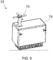
- Fig. 3 shows an example element from the AMISR UHF technology, with a cross-dipole antenna 70.
- the transmit, receive electronics for this example element may reside with the housing 75.
- the antenna pattern and the shape of the housing may differ from that shown in the figure, depending on many factors including frequency and the application as examples. Referring back to Fig. 1 , with the array of elements as shown one may obtain beam steering in the X-dimension or azimuth direction.
- grating lobes may limit steering angles. Grating lobes occur when the spacing of individual elements in an array is equal to or greater than half the wavelength. Similarly, the location of the grating lobes depends on the inter-element spacing and the frequency of the signal. To maximize the steering angle, the elements may be spaced close to a half-wavelength. With this configuration, a single array of elements can scan the X-Z plane. Elevation angle diversity may be achieved in multiple ways and will be described further below.
- the base of the entire reflector structure may be movable.
- the need for a movable base might arise, for example, in a communications system due to the need to track a single orbital plane as it precesses across the sky from revolution to revolution.
- a movable base then allows the satellites in the given orbital plane to remain in the scanning plane of the 1D phased array system.
- a system of motors and actuating mechanisms under control of a control system may provide the motion of the base. With this control system, the amount and type of motion may be calculated based on a number of situations such as but not limited to the projected path of a satellite or of other objects. The projected path can be calculated based on measurements or other data and by using an orbit model.
- the 1D trough antenna has a reflector 20.
- This reflector may consist of various materials including aluminum, steel, a metal mesh or a metallized foam pad, as examples. These materials may be chosen based on a number of factors including cost of materials, cost of fabrication and for what specific applications the trough antenna is designed, as examples.
- a lighter material may be chosen.
- the lighter materials may include aluminum, cast magnesium or the metal mesh, as examples. This may reduce the requirements on the size and capacity of the actuators that move the base.
- Figs. 4 and 5 illustrate example directivity and radiation patterns from a 1D parabolic trough system. This embodiment consists of 9 transmit elements operating at 446 MHz with an element spacing of 0.37 meters, illuminating a 16-meter long trough with a parabolic aperture of 13 meters.
- Fig. 4 illustrates the XZ plane far field directivity plane.
- the various curves illustrate the directivity pattern for different beam steering angles. For example, curve 100 illustrates the directivity pattern for a beam steered at 0° whereas curve 110 illustrates the beam at 57.3°.
- Fig. 5 illustrates the same information in a polar plot, except this plot illustrates the steering of the beam.
- Fig. 6 illustrates how this steering may be utilized to cover the imaging field.
- a section of the earth is shown as 120.
- the imaging field of the 1D system is shown as 130.
- the 1D system can sweep this area in transmit and receive operation by adjusting the phases for each element.
- Multiple 1D systems may deploy to scan multiple sections of the sky, with multiple possibilities for configurations.
- two 1D systems may be located and oriented in such a way that they point to different directions in the sky.
- two 1D systems could reside at the same ground location, with one system pointing northwards and the other pointing southwards with the scanning direction in the east-west plane.
- Fig. 7 illustrates the orientation of such a combined system.
- 10A and 10B are 1D systems oriented in a northward and southward direction respectively.
- Arrows 12A and 12B indicate the scanning plane with the plane going perpendicularly into the plane of the paper.
- Fig. 8 shows the angular plot of the sky looking upwards and curves 130A and 130B indicate the angular extent of the imaging field corresponding to the 1D phased array systems 10A and 10B respectively, projected on the angular plot.
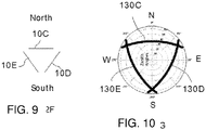
- Fig. 9 illustrates another configuration.
- three 1D systems deploy with one pointing north 10C, another pointing southeast 10D and a third pointing south-west 10E.
- Fig. 10 illustrates a plot with the angular extent of the scans as curves 130C, 130D and 130E.
- the lines 130A-130E curve due to the projection of the straight line onto the angular plot.
- these plots are spheres and the curves show where the scanning planes intersect with the sphere.
- the 1D systems are arranged in such a manner to detect any object above a certain size, flying in certain orbits in the patch of space above the systems.
- the configuration of Figs. 7 and 8 can detect objects flying on north south orbits. However, with this configuration objects flying due east-west or west east may go undetected, and other inclinations might result in a detection by only one of the systems.
- Figs. 9 and 10 mitigates these issues as objects flying in any orbit may be detected.
- the configuration may provide at least two observations of the object. This allows an appropriate choice depending on the requirements of detection.
- these systems need not be co-located in one location. The systems could be placed far apart, for example, one on each pole and one on the equator.
- the antenna can only detect spacecraft within line of sight and within its sensitivity limits, satellites or debris in low inclination orbits would not be detectable from a polar station. Therefore, multiple equatorial sites are recommended so that a low-inclination satellite can be observed multiple times per revolution.
- Multiple 1D-systems may also be used to achieve elevation angle diversity. This may be achieved by arranging the systems 10G and 10F at an angle to each other and to the XY plane. The scanning plane would then point at different elevation angles with different fields of view 130G and 130F as shown in Figure 11 .
- a movable base enables changes to the position of the 1D system as described above.
- the 1D system may include mechanisms that allow adjustment of orientation.
- the base 50 may move by a system of gears, motors or other types of actuators, not shown in the figure.
- the mechanisms may allow rotation of the entire system about the Z-axis.
- Other mechanisms may allow changing the orientation of the trough antenna.
- the arrow 12A or 12B would point at a different angle when orientation changes. In this case, the actuating mechanisms would cause the trough to point in a different direction.
- the ability to adjust or modify the position and orientation may have advantages in many situations. In one example, modifications of the shape of the fenced area may enable better detection of a target. Referring to Fig. 8 , if an object flew across the sky in a mostly east-west direction with a small south-east to north-west angle so that the object and the field-of-view of the 1D system intersected very briefly or for a short period of time, one or both the 1D-systems shown in Fig. 7 may rotate around their Z-axes. The next time the object comes around, if it is circling the earth, the rotated systems may obtain a better signal.
- the length and the diameter of the trough represent only a few of the many design parameters for the 1D phased array antenna system.
- the gain of the antenna is one factor considered when making the design choice of the length and diameter.
- Fig. 12 shows a calculation of the antenna gain as a function of trough diameter and length for a UHF system. It also shows that if a particular gain is desired, the diameter and the length may be varied as best suited for the environment in which the 1D system will deployed.
- the required trough size for a radar application is determined by a number of factors, including the detectability of the target.
- P tx is the transmit power
- G tx is the transmit gain
- G rx is the receive gain
- ⁇ rcs is the radar-scattering cross-section
- ⁇ is the radar wavelength
- R tx is the transmit range to the target
- R rx is the receive range to the target
- L is a loss factor.
- T int F safety k B T sys F duty P rx
- k B Boltzmann's constant
- T sys is the system temperature
- F duty is the system duty cycle
- F safety is a detectability safety margin
- ⁇ rcs 4 ⁇ 3 R tx 2 R rx 2 L P tx G tx G rx ⁇ 2 F safety k B T sys F duty T int .
- mapping the RCS to a physical object size depends on the object scattering properties, material, and many other factors.
- C obj 2 ⁇ R obj is less than approximately 0.1 ⁇ .
- the RCS can be treated using Mie scattering and the RCS is more difficult to predict.
- the RCS approaches the optical crosssection ( A obj ) . Given a desired minimal detectable cross-section at the desired range, as well as the desired integration time, the system parameters can be computed.
- Fig. 13 illustrates an example of a trough geometry.
- the trough 20, shown as a solid line, is seen to be part of a parabolic arc 25, shown as a dashed line.
- the feed point is indicated. This is where the elements of the 1D array may be located, going into the plane of the paper. In this particular example, the feed point is located at 5.63 m above the lowest point of the parabola. The angle from the feed point the edge of the trough is 60°. The depth of the dish in this case is 1.88 m. These numbers are dependent on the beam pattern of the element.
- a sub-reflector may offer additional advantages to the trough design. This is an additional reflector that may be located between the feed and the main trough. It may be used to redirect, focus, or spread the radio frequency energy traveling between the feed and the main trough. Using the sub-reflector antenna gain and sidelobe levels may be further optimized. It may also reduce the cost to service the feed because the feedpoint can be located closer to ground level. Furthermore, the orientation of the feed antenna equipment can be adjusted to make installing and servicing easier, and so that gravity-fed moisture drainage holes do not interfere with electronics or ground planes.
- Table 1 illustrates example configurations of a 1D system as described above.
- Power-aperture product measures the performance of radars.
- the table compares a trough array and a 2D array. From this table, it can be seen that for a 500 Watt UHF system, for an object with diameter of 10 cm, given the same power-aperture product, the 1D system has a trough length of 49m and a width of 13m compared to a linear dimension of 13.71 m for the 2D array. However, the number of elements required in the 1D system is 147 compared to 1690 for the 2D array. This illustrates the cost advantage of the ID-system.
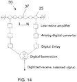
- Figs. 14-16 show some examples of receiver beamformer architectures. Beamformer architectures are well known and understood. Figure 14 is the most general configuration, where the signals from N elements are amplified and digitized, and fed into an N-channel beamformer functionally consisting of a digital delay and summation. While attractive, this solution may be prohibitively expensive for commercial applications because the beamformer requirements might be excessive, for example requiring 2 GHz bandwidth over 1000 channels.
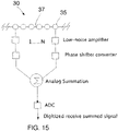
- Fig. 15 shows an alternative solution of an analog beamforming approach.
- every signal is amplified then sent to a phase shifter bank and summed, producing an N-channel analog stream. The signal is then digitized.
- This configuration requires fewer digitizers.
- Fig. 16 illustrates a hybrid approach where groups of channels, 1 to M in the example, are summed. The partial sums are then digitized to form a total sum.
- Each configuration has its own advantages and disadvantages in terms of cost, power usage and beamformer precision. These are well known in the literature and will not be described here. Additionally, while the figures describe the receive signal path, the transmit signal path is similar and will not be repeated here.
- Coherent processing is a technique to improve signal to noise ratio (SNR) which increases detectability for radar applications.
- SNR signal to noise ratio
- the bandwidth of the transmitted waveform determines the range resolution for a radar.
- the range resolution is given by cT baud / 2 where c is the speed of light. While this is the fundamental resolution over which the radar can resolve, interpolation can be used to improve the statistical range measurement accuracy to greater than 10 times this value, in the case of high SNR returns.
- e(t) is the slow-time varying complex envelope of the transmission
- ⁇ 0 is the radian carrier frequency.
- Doppler resolution is determined by 1 / T in the above equation.
- Coherent processing increases SNR and significantly improves Doppler resolution.
- coherent integration produces a large advantage over limited time intervals as long as the signals from the targets remain coherent. Changes in the system's viewing angle, satellite orientation (rotation), or the state of the ionosphere cause returns to lose coherence. This reduced coherence reduces the effectiveness of coherent integration algorithms.
- a scheme that combines short coherent integration intervals with longer incoherent integration intervals often yields optimal system performance.
- Several types of incoherent integration of operations may be done. As an example, the summation may be carried out after detection or the power from each channel may be summed.
- the radar resolution is determined by the transmit bandwidth.
- frequency chirps are often used to provide this bandwidth broadening.
- the performance of these systems is limited by the presence of clutter and interference, and frequency chirps have an inherent range-Doppler ambiguity.
- Randomization of the transmit pulse parameters provides an advantageous technique to overcome some of these issues, especially if multiple targets over a wide range of altitudes are being tracked.
- the pulse length ( T pulse ) the interpulse time (T ipp ) can be randomized, occasionally called aperiodic coding.
- the baud length (T baud ) described earlier can also be randomized.
- a statistical property of pseudorandom sequences is that they are orthogonal. For two pseudorandom sequences this can be mathematically written as: ⁇ S 1 t
- S 2 t ⁇ 0
- Randomized pulse sequences make use of this statistical property to reduce or eliminate ambiguous self-clutter from unwanted ranges.
- randomized pulse sequences may be used to detect objects at different altitudes. In a string of pulses which have been randomized, one pulse may be used for a low earth orbit object detection whereas the combination of many pulses may be treated as a longer pulse sequence for geosynchronous equatorial orbit (GEO) object detection (which are at higher altitudes).
- GEO geosynchronous equatorial orbit
- each pulse can have a unique random sequence so that when the receive signals from one transmit pulse are decoded, signals from other pulses do not clutter the signals from the first pulse, and essentially get randomized into noise.
- a conventional radar may not discriminate between the two.
- using randomization of the pulse with unique sequences it becomes possible to identify where the receive signals originated from.
- randomization of the T ipp using aperiodic sequences would be advantageous for high altitude targets. This is because the detection of targets that are at high altitudes (e.g., GEO) typically takes 100s of milliseconds, over which several pulses are transmitted.
- IPP transmitter inter-pulse period
- the combination of an electronically scanned phased array and coherent processing leads to the ability to track multiple objects simultaneously with good range and Doppler resolution.
- 10 objects can be tracked simultaneously with a UHF system with an estimated object coherency time of 100 ms, with a Doppler resolution of 10 Hz (3.35 m/s at UHF).
- the object would remain in the beam for 5s and the time spent per object would be 500 ms.
- the number of coherent range and Doppler estimates would be 5 while the object is in the beam.
- the transmit pulses may be sometimes coded to enhance parameters such as signal to noise ratio. These coded signals have to be decoded when they are received at the 1D system.
- a copy of the intended transmit waveform is used during the decoding process.
- using the copy of the intended transmit waveform may result in unsatisfactory levels of artifacts due to improper decoding. This is because the actual transmit waveform emanating from the individual elements may be different that the intended waveform due to distortions in phase, amplitude, and timing. It is advantageous to use the actual transmit waveform for the decoding process.
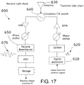
- Fig. 17 illustrates this concept. This figure shows some of the functional processing blocks of the transmit/receive system.
- An example of an intended transmit signal 620 is shown at the output of the signal generator 610. As this signal propagates through to the antenna 630 and is transmitted, it will undergo further magnitude and phase changes. After transmission, the signal travels to the target and reflects back to the antenna.
- the receiver electronics which may include a processor executing instructions, processes this signal. As shown, the signal at the output of the receive beamformer 670 may be different in magnitude and phase compared to the intended transmit signal 620.
- Using the intended waveform to decode the receive signal may lead to artifacts.
- a signal that is propagated through the transmit and receive functional blocks but not propagated into free space is used. This signal results from leaks caused by the circulator or the transmit/receive switch 640 designed with some coupling. During the transmit operation, some amount of signal couples from the transmit side to the receive side. This coupled signal is then digitized and stored and used for decoding the receive signals from the target.
- Inverse Synthetic Aperture Radar is a technique for imaging an object, such as a piece of debris or a spacecraft, with multiple radar systems. These images can identify the object, especially if it is large, and improve the ability to link measurements taken by one radar with measurements taken at another radar.
- the quality of the image formed using the ISAR technique is dependent on the satellite motion and signal bandwidth.
- the images formed using this technique are two dimensional, with one axis pointed along the axis of the trough and the other axis pointed in the range direction away from the trough. The best image resolution is achieved when the radar can view the object from horizon to horizon, and when the radar has a very wide bandwidth.
- the use of the 1D system with inter-element spacing less than or equal to ⁇ / 2 is advantageous in this case as it allows the use of steered beams; this improves the time that a target is visible to the 1D system thus enabling the formation of ISAR images.
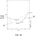
- Fig. 18 illustrates an example trough geometry.
- the feedpoint is seen approximately 5m directly above the lowest point of the trough and approximately 6m away from the edge of the dish. In may be difficult to have physical access to the feedpoints without special equipment. In addition to the issue of access, having the feedpoint directly above the trough increases blockage of the signals in the main part of the beam.
- Fig. 18 another configuration is shown which overcomes these issues.
- the feed point is located to the side of the antenna and not directly above it but still at the focal point of the parabola.
- the feed elements are rotated 60°, facing the trough. This results in an aperture of 13m for the trough however as can be seen from the figure, the feed points are only about 3.7m over the bottom of the trough.
- Fig. 19 shows another configuration where the feed points are rotated 55°. Here the feed points are about 3m above and about 2m away from the edge of the dish. Other offset configurations are also possible. These configurations lower the feed points as well as make it more accessible. These configurations also minimize the blockage caused by the feedpoints.
- the process of calibration may generally consist of at least two steps.
- an electromagnetic model of the system which included the geometry of the elements and the 1D trough, may be generated based on measuring the position of the elements from a reference point. These measurements can be made for example with a laser device or from multiple aerial photographs from multiple angles from which a 3D model of the system is built.
- a second step requires a calibration antenna located at a known position. Each element sends and receives signals from the calibration antenna one by one. Now the measured phase of the received signals is compared to the predicted phase from the model for each element.
- the electromagnetic model may also contain the location of the calibration antenna.
- These deviations on an element-by-element basis provide the phase distortion or modification that occur due to the electronics and other factors.
- These deviation values called calibration values, are obtained for transmit and receive operation separately.
- the reverse of the above operation is performed; in other words, signals are transmitted from each element on an element-by-element basis and received at the calibration antenna.
- the appropriate transmit or receive values are then applied when the system is in operation again on an element-by-element basis.
- Electromagnetic waves travelling through the ionosphere can experience delays in the UHF band. This may lead to time-variable bases in the range measurements.
- the phase delay incurred by electromagnetic waves through the ionosphere is 40.3 TEC / f, where TEC is the total electron content (units of electrons per m2) and/is the operating frequency in Hz.
- Two-way range delays could be in the range of 10-100 meters, and highly variable because of variability in ionospheric conditions. This is especially true at mid and low latitudes where the ionosphere is most variable.
- the conventional way to address this issue includes modeling the ionosphere and using the model to correct the range measurements.
- the ionospheric characteristics change as a function of location and time, reducing the value of using the model for error correction.
- the incoherent scatter resulting from transmitting measurement pulses is received and analyzed. By using the pulse and amplitude of the received signals, a real-time model of the ionosphere is generated. Use of this model may result in more accurate range estimates.
- incoherent scatter is thermal backscatter from ionospheric electrons, as discussed by J. V. Evans in "Theory and Practice of Ionosphere Study by Thomson Scatter Radar," Proceedings of the IEEE, vol. 57, no. 4, pp. 496-530, 1060 .
- ⁇ e is the radar cross-section of an electron
- T e and T i are the electron and ion temperatures
- ⁇ is a wavelength-dependent plasma Debye-length term.
- the total received power is then proportional to the total number of electrons within the illuminated volume, and thus the electron number density N e , as well as the power aperture product.
- the received power decreases as: P S ⁇ P t A eff N ⁇ ⁇ R 2
- ISRs can effectively profile the electron number density, as well as other properties of the medium through interpretation of the IS Doppler spectrum.
- ionospheric probing pulses can be interleaved with the satellite tracking pulses to measure range-resolved profiles of the electron density.
- the ionospheric total electron content (TEC) between the transmitter and satellite can be computed by integrating the measured electron density along the path from the transmitter to the satellite.
- the range delay can be computed through the phase delay equation above.
- LEO low earth orbit
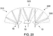
- Fig. 20 illustrates a configuration where multiple beams are generated. This is an advantageous configuration for a communications system with the requirement to uplink and/or downlink with multiple satellites simultaneously.
- three 1D systems are illustrated although the multiple beams can be generated with just one system.
- the imaging field-of-view of each 1D system is illustrated by 310, 320, and 330.
- the S-band (2-4 GHz) may be used for uplink and X-band (8-12GHz) may be used for the downlink.
- uplink refers to the communication between the ground stations to the satellites and downlink refers to the communication from the satellite to the ground stations.
- Some protocols for downlinking data from satellites require that an uplink be established and maintained during the download. This is done to obtain information about the quality of the link and to determine the data rate to be used for the downlink.
- the uplink requires only a low data rate, for example, often a narrow bandwidth beam (about 1-2 MHz) is sufficient for the uplink.
- a wider bandwidth is often necessary. For example, an appropriate bandwidth may be around 100MHz.
- the uplink and downlink may be used for the uplink and the Ka band (26.5-40GHz) may be used for the downlink.
- the antennas for the two different bands can be configured in the context of a 1D system. In one configuration, the two 1D phased arrays are arranged so that they are horizontally offset. This is illustrated in Fig. 9A.
- the location indicated by 500 may be the location of the X-band downlink feed whereas the location indicated by arrow 510 may be the location of the S-band uplink feed.
- Arrow 520 indicates the distance by which the S-band is offset. In this case the X-band feed is placed at the focus point of the trough and the S-band is horizontally offset. Various rules may be used to calculate the amount of horizontal offset shown at 520. However, one preferred configuration is to place the higher frequency antenna at the focus and offset the lower frequency antenna and make this offset to equal 1 ⁇ 4 (X-band wavelength + S-band wavelength), which effectively places the feeds side by side. Feeds are often half a wavelength in width.
- the maximum offset causing 3 dB of degradation to the uplink system is 4.6 cm.
- offsetting the feed changes the pointing direction of the main beam. If the changes are large enough, then the antenna will not point at the satellite but instead at blank sky nearby. For example, given the offset of 4.6 cm above and a trough width of 2 meters, Table 2 below shows the change in pointing direction of the S-band beam in degrees ( ⁇ ) for various focal heights shown as 530. The table also shows what the X-band feed angle in degrees ( ⁇ ) is for these focal heights.
- the feed angle is the width of the trough, measured as an angle, when viewed from the location of the feed.
- the system will perform best when the beam width of the feed equals the feed angle of the trough, otherwise the trough is over-illuminated that wastes energy or under-illuminated which does not maximally utilize the trough.
- a beam width of 90° is common for commercially available feeds. Changing the curvature of the trough, from the X-band example discussed above, so that the feed angle is 90° results in an optimal focal height of 1.2m.
- the S-band antenna may be offset vertically from the X-band antenna, which would be placed at the focus of the reflector.
- Fig. 22 illustrates this situation.
- the S-band antenna is placed at location 540 whereas the X-band antenna is placed at location 500,
- the vertical offset is indicated by arrow 550 and as before, the focal height is indicated by 530.
- Various rules may be used to calculate the amount of vertical offset 550.
- the vertical offset is chosen such that the path length difference between the rim ray and the vertex ray, path length between 540 to 550 and back up to 560, is 90°. This condition ensures that the reflected ray coming from the edge of the reflector and from location 560 interfere neither constructively or destructively. Rays emanating from all other points interfere more and more constructively.
- the 1D system can be made in sections and each section may have only one type of feed antenna. This is the case of the ID communications system having three sections, the middle section may be the X-band and the outer two sections can be the S-band.
- a dichroic sub-reflector is placed between the trough and the prime focus 500 in Fig. 22 along the line segment connecting 500 and 550 in fig. 9B.
- One feed may be placed at the prime focus and the other feed may be placed to the side of the trough, behind the trough, or between the trough and the dichroic reflector. If the second feed is behind the trough, then a hole must be formed in the trough to allow radio frequency energy to pass between the sub-reflector and the feed.
- the dichroic sub-reflector may be designed to be transparent at the frequency of first feed, so the first feed sees the trough as if the sub-reflector were not present.
- the dichroic sub-reflector may be designed to be highly reflective at the frequency of the second feed.
- the sub-reflector redirects the energy to focus at a new point at a different location than the prime focus of the trough. This creates two focus points for the system, each at a distinct frequency and location, so that the performance of both feeds may be optimize and the feeds do not need to be located close to one another.
- the preferred configuration is to use two sections - one section dedicated to the uplink and the other section dedicated to the downlink - with all the feeds placed at the optimum locations, the focus points. This is done because using offset feeds can be a very expensive design challenge. Placing feeds side-by-side or one-behind-the-other can lead to electromagnetic coupling and radio frequency interference, whereby signals from the transmit system (uplink) corrupt the receive system (downlink). The additional design cost for offset feeds is often larger than simply building multiple troughs.
- the length and width of the trough antenna may be determined.
- the total collecting area of the trough may be determined.
- the orbital plane of the satellites may be used to determine the width of the antenna as the width determines the width of the elevation beam.
- the choice of the width and the size of the elevation beam may be such that the satellite always remains with the scanning plane of the 1D system.
- the width and collecting area calculated as described above the length of the trough may be determined.
- the 1D systems described above may be configured as part of a satellite control system.
- the system may be used to send alerts when expected targets do not get detected. This may happen for example when satellites drift from their orbits. In particular, low altitude satellites are more prone to drifting due to atmospheric drag. When a satellite is expected but not detected, alerts can be sent out to the operators.
- the scanning pattern of the 1D system may be modified to try and find the satellite. For example, the field-of-view may be broadened to a larger angle so that more area is covered.
- the 1D system may be repositioned in one of various ways to try and find the satellite.
- the discussion also applies to 2D phased arrays.
Landscapes
- Physics & Mathematics (AREA)
- Electromagnetism (AREA)
- Variable-Direction Aerials And Aerial Arrays (AREA)
- Radar Systems Or Details Thereof (AREA)
- Aerials With Secondary Devices (AREA)
Priority Applications (1)
| Application Number | Priority Date | Filing Date | Title |
|---|---|---|---|
| RS20220637A RS63456B1 (sr) | 2015-04-08 | 2016-04-08 | 1d fazirani antenski niz za radar i komunikacije |
Applications Claiming Priority (5)
| Application Number | Priority Date | Filing Date | Title |
|---|---|---|---|
| US201562144473P | 2015-04-08 | 2015-04-08 | |
| US201562167641P | 2015-05-28 | 2015-05-28 | |
| US201562190378P | 2015-07-09 | 2015-07-09 | |
| US201562239993P | 2015-10-12 | 2015-10-12 | |
| PCT/US2016/026697 WO2016164758A1 (en) | 2015-04-08 | 2016-04-08 | 1d phased array antenna for radar and communications |
Publications (3)
| Publication Number | Publication Date |
|---|---|
| EP3281250A1 EP3281250A1 (en) | 2018-02-14 |
| EP3281250A4 EP3281250A4 (en) | 2018-10-10 |
| EP3281250B1 true EP3281250B1 (en) | 2022-04-27 |
Family
ID=57072168
Family Applications (1)
| Application Number | Title | Priority Date | Filing Date |
|---|---|---|---|
| EP16777378.7A Active EP3281250B1 (en) | 2015-04-08 | 2016-04-08 | 1d phased array antenna for radar and communications |
Country Status (10)
| Country | Link |
|---|---|
| US (2) | US11024958B2 (sr) |
| EP (1) | EP3281250B1 (sr) |
| AU (1) | AU2016246770B2 (sr) |
| ES (1) | ES2923897T3 (sr) |
| HU (1) | HUE059239T2 (sr) |
| NZ (1) | NZ737041A (sr) |
| PL (1) | PL3281250T3 (sr) |
| PT (1) | PT3281250T (sr) |
| RS (1) | RS63456B1 (sr) |
| WO (1) | WO2016164758A1 (sr) |
Cited By (1)
| Publication number | Priority date | Publication date | Assignee | Title |
|---|---|---|---|---|
| US20240063542A1 (en) * | 2021-02-24 | 2024-02-22 | Bluehalo, Llc | System and method for a digitally beamformed phased array feed |
Families Citing this family (17)
| Publication number | Priority date | Publication date | Assignee | Title |
|---|---|---|---|---|
| AU2016246770B2 (en) | 2015-04-08 | 2020-07-16 | Sri International | 1D phased array antenna for radar and communications |
| US10177434B1 (en) * | 2016-12-23 | 2019-01-08 | X Development Llc | Parabolic reflector combined with phased array feed for long range communication |
| DE102016125874B3 (de) | 2016-12-29 | 2018-02-15 | Deutsches Zentrum für Luft- und Raumfahrt e.V. | Erfassungseinrichtung |
| DE102016125853B3 (de) * | 2016-12-29 | 2018-02-15 | Deutsches Zentrum für Luft- und Raumfahrt e.V. | Erfassungssystem |
| US10840998B2 (en) * | 2017-06-21 | 2020-11-17 | Blue Digs LLC | Broadband satellite terminal |
| WO2020070735A1 (en) * | 2018-10-02 | 2020-04-09 | Rfisee Ltd | Two-dimensional phased array antenna |
| US10698099B2 (en) | 2017-10-18 | 2020-06-30 | Leolabs, Inc. | Randomized phase and amplitude radar codes for space object tracking |
| US10921427B2 (en) | 2018-02-21 | 2021-02-16 | Leolabs, Inc. | Drone-based calibration of a phased array radar |
| CN109581363B (zh) * | 2018-12-03 | 2022-04-22 | 中国电波传播研究所(中国电子科技集团公司第二十二研究所) | 一种基于非相干散射雷达的小尺寸空间碎片检测和参数提取方法 |
| US11378685B2 (en) | 2019-02-27 | 2022-07-05 | Leolabs, Inc. | Systems, devices, and methods for determining space object attitude stabilities from radar cross-section statistics |
| WO2020194423A1 (ja) * | 2019-03-25 | 2020-10-01 | 株式会社日立国際電気 | 無線通信装置 |
| JP7644501B2 (ja) * | 2019-05-09 | 2025-03-12 | ビュー オペレーティング コーポレーション | 建物内の制御されたカバレッジのためのアンテナシステム |
| CN114397626B (zh) | 2019-07-22 | 2025-09-16 | 深圳引望智能技术有限公司 | 一种雷达系统及车辆 |
| KR102883635B1 (ko) * | 2019-10-11 | 2025-11-07 | 레오랩스, 인크. | 레이더 보정 및 우주 물체 추적 |
| US12609448B2 (en) * | 2020-10-01 | 2026-04-21 | Google Llc | Collocated mmWave and sub-6 GHz antennas |
| US20240255610A1 (en) * | 2021-05-13 | 2024-08-01 | Leolabs, Inc. | Computing technologies for detecting and tracking space objects via combinations of incoherent processing, dynamic detection, and coherent and/or correlator processing |
| CN120871139B (zh) * | 2025-09-28 | 2025-12-05 | 中国科学院海洋研究所 | 基于Ku/Ka双频SAR测高的亚中尺度信号提取方法 |
Family Cites Families (36)
| Publication number | Priority date | Publication date | Assignee | Title |
|---|---|---|---|---|
| US2471284A (en) * | 1945-05-25 | 1949-05-24 | Bell Telephone Labor Inc | Directive antenna system |
| US2969542A (en) * | 1959-03-30 | 1961-01-24 | Coleman Henri Paris | Spiral antenna system with trough reflector |
| US3612845A (en) | 1968-07-05 | 1971-10-12 | Reed C Lawlor | Computer utilizing random pulse trains |
| US4500882A (en) * | 1980-11-05 | 1985-02-19 | Mitsubishi Denki Kabushiki Kaisha | Antenna system |
| US4780726A (en) * | 1984-12-03 | 1988-10-25 | Trw Inc. | Depolyable reflector |
| US4769777A (en) | 1986-06-25 | 1988-09-06 | General Electric Company | Unpredictable bit stream generator |
| US5130718A (en) * | 1990-10-23 | 1992-07-14 | Hughes Aircraft Company | Multiple dichroic surface cassegrain reflector |
| US5115246A (en) | 1991-02-27 | 1992-05-19 | The United States Of America As Represented By The Secretary Of The Air Force | Radar target locating and tracking apparatus using a dual-interleaved pulse train radar waveform |
| US5570307A (en) | 1995-01-06 | 1996-10-29 | Vlsi Technology, Inc. | Digital randomizer for on-chip generation and storage of random self-programming data block |
| US5748140A (en) | 1996-03-28 | 1998-05-05 | Hughes Electronics | System for tracking radar targets in background clutter |
| GB2326284A (en) * | 1997-06-11 | 1998-12-16 | Siemens Plessey Electronic | Wide bandwidth antenna arrays |
| JP2942923B2 (ja) | 1997-11-27 | 1999-08-30 | 株式会社ジーデイーエス | ランダムパルス型レーダー装置 |
| US6271786B1 (en) | 1999-06-07 | 2001-08-07 | Raytheon Company | Random noise radar target detection device |
| US6169522B1 (en) | 1999-09-03 | 2001-01-02 | Motorola, Inc. | Combined mechanical scanning and digital beamforming antenna |
| US6320553B1 (en) | 1999-12-14 | 2001-11-20 | Harris Corporation | Multiple frequency reflector antenna with multiple feeds |
| US6522210B1 (en) | 2000-02-16 | 2003-02-18 | Honeywell International Inc. | Random pulse generator |
| US6823170B1 (en) | 2000-07-26 | 2004-11-23 | Ericsson Inc. | Satellite communications system using multiple earth stations |
| WO2002031915A2 (en) * | 2000-10-13 | 2002-04-18 | Motorola, Inc. | Tracking antenna and method |
| US6664939B1 (en) | 2001-03-28 | 2003-12-16 | Mark Olinyk | Foam-filled antenna and method of manufacturing same |
| US6456231B1 (en) | 2001-06-01 | 2002-09-24 | Mcewan Technologies, Llc | Radar sensor having a CFAR detector |
| US6862605B2 (en) | 2001-08-15 | 2005-03-01 | Scott A. Wilber | True random number generator and entropy calculation device and method |
| US7123876B2 (en) * | 2001-11-01 | 2006-10-17 | Motia | Easy set-up, vehicle mounted, in-motion tracking, satellite antenna |
| GB2397957A (en) | 2003-01-30 | 2004-08-04 | Qinetiq Ltd | Target detection |
| US6914554B1 (en) | 2003-10-17 | 2005-07-05 | The United States Of America As Represented By The Secretary Of The Army | Radar beam steering with remote reflectors/refractors |
| US6965351B1 (en) * | 2004-03-29 | 2005-11-15 | Lockheed Martin Corporation | Dual-frequency-illuminating reflector |
| US6933888B1 (en) | 2004-06-14 | 2005-08-23 | Bae Systems Information And Electronic Systems Integration Inc. | Multi-ship coherent geolocation system |
| US7250902B2 (en) | 2005-07-19 | 2007-07-31 | Raytheon Company | Method of generating accurate estimates of azimuth and elevation angles of a target for a phased—phased array rotating radar |
| US7375676B1 (en) | 2006-03-07 | 2008-05-20 | Lockheed Martin Corporation | Mutual interference processor for pulse radar |
| CA2680849A1 (en) | 2007-03-16 | 2008-09-25 | Mobile Sat Ltd. | A vehicle mounted antenna and methods for transmitting and/or receiving signals |
| JP2009068896A (ja) | 2007-09-11 | 2009-04-02 | Fuji Heavy Ind Ltd | 等価時間サンプリングレーダ |
| US8378878B2 (en) | 2010-08-05 | 2013-02-19 | ARETé ASSOCIATES | Creating and processing universal radar waveforms |
| EP2637253A4 (en) * | 2011-12-29 | 2014-12-17 | Quantrill Estate Inc | UNIVERSAL ENERGY CONCENTRATION DEVICE |
| US20140225796A1 (en) | 2013-02-08 | 2014-08-14 | Chien-An Chen | Ultra-broadband offset cassegrain dichroic antenna system for bidirectional satellite signal communication |
| AU2014288997B2 (en) | 2013-07-10 | 2017-11-09 | Bae Systems Plc | Interference nulling of multipath signals in stacked beam pulse radar |
| US9761049B2 (en) | 2014-03-28 | 2017-09-12 | Intel Corporation | Determination of mobile display position and orientation using micropower impulse radar |
| AU2016246770B2 (en) | 2015-04-08 | 2020-07-16 | Sri International | 1D phased array antenna for radar and communications |
-
2016
- 2016-04-08 AU AU2016246770A patent/AU2016246770B2/en active Active
- 2016-04-08 ES ES16777378T patent/ES2923897T3/es active Active
- 2016-04-08 EP EP16777378.7A patent/EP3281250B1/en active Active
- 2016-04-08 NZ NZ737041A patent/NZ737041A/en unknown
- 2016-04-08 RS RS20220637A patent/RS63456B1/sr unknown
- 2016-04-08 US US15/561,682 patent/US11024958B2/en active Active
- 2016-04-08 WO PCT/US2016/026697 patent/WO2016164758A1/en not_active Ceased
- 2016-04-08 HU HUE16777378A patent/HUE059239T2/hu unknown
- 2016-04-08 PT PT167773787T patent/PT3281250T/pt unknown
- 2016-04-08 PL PL16777378.7T patent/PL3281250T3/pl unknown
-
2021
- 2021-02-08 US US17/169,767 patent/US11539130B2/en active Active
Non-Patent Citations (1)
| Title |
|---|
| HERD J ET AL: "Advanced architecture for a low cost Multifunction Phased Array Radar", MICROWAVE SYMPOSIUM DIGEST (MTT), 2010 IEEE MTT-S INTERNATIONAL, IEEE, PISCATAWAY, NJ, USA, 23 May 2010 (2010-05-23), pages 676 - 679, XP031714020, ISBN: 978-1-4244-6056-4 * |
Cited By (10)
| Publication number | Priority date | Publication date | Assignee | Title |
|---|---|---|---|---|
| US20240063542A1 (en) * | 2021-02-24 | 2024-02-22 | Bluehalo, Llc | System and method for a digitally beamformed phased array feed |
| US12062862B2 (en) * | 2021-02-24 | 2024-08-13 | Bluehalo, Llc | System and method for a digitally beamformed phased array feed |
| US20240396215A1 (en) * | 2021-02-24 | 2024-11-28 | Bluehalo, Llc | System and method for a digitally beamformed phased array feed |
| US20250007164A1 (en) * | 2021-02-24 | 2025-01-02 | Bluehalo, Llc | System and method for a digitally beamformed phased array feed |
| US12316027B2 (en) | 2021-02-24 | 2025-05-27 | Bluehalo, Llc | System and method for a digitally beamformed phased array feed |
| US12519233B2 (en) | 2021-02-24 | 2026-01-06 | Bluehalo Llc | System and method for a digitally beamformed phased array feed |
| US12542355B2 (en) * | 2021-02-24 | 2026-02-03 | Bluehalo, Llc | System and method for a digitally beamformed phased array feed |
| US12548904B2 (en) * | 2021-02-24 | 2026-02-10 | Bluehalo, Llc | System and method for a digitally beamformed phased array feed |
| US12555908B2 (en) | 2021-02-24 | 2026-02-17 | Bluehalo, Llc | System and method for a digitally beamformed phased array feed |
| US12609449B2 (en) | 2021-02-24 | 2026-04-21 | Bluehalo, Llc | System and method for a digitally beamformed phased array feed |
Also Published As
| Publication number | Publication date |
|---|---|
| EP3281250A4 (en) | 2018-10-10 |
| RS63456B1 (sr) | 2022-08-31 |
| HUE059239T2 (hu) | 2022-11-28 |
| AU2016246770B2 (en) | 2020-07-16 |
| CA2984133A1 (en) | 2016-10-13 |
| US11024958B2 (en) | 2021-06-01 |
| US11539130B2 (en) | 2022-12-27 |
| WO2016164758A1 (en) | 2016-10-13 |
| PL3281250T3 (pl) | 2022-10-17 |
| AU2016246770A1 (en) | 2017-11-30 |
| US20210167496A1 (en) | 2021-06-03 |
| US20180083357A1 (en) | 2018-03-22 |
| NZ737041A (en) | 2022-07-29 |
| ES2923897T3 (es) | 2022-10-03 |
| EP3281250A1 (en) | 2018-02-14 |
| PT3281250T (pt) | 2022-07-27 |
Similar Documents
| Publication | Publication Date | Title |
|---|---|---|
| US11539130B2 (en) | 1D phased array antenna for radar and communications | |
| Ignatenko et al. | ICEYE microsatellite SAR constellation status update: Evaluation of first commercial imaging modes | |
| US8723719B1 (en) | Three dimensional radar method and apparatus | |
| US11965954B2 (en) | Apparatus and method for monitoring objects in space | |
| US9989634B2 (en) | System and method for detection and orbit determination of earth orbiting objects | |
| CN108008380A (zh) | 一种基于卫星编队的微波凝视关联成像方法及系统 | |
| Blázquez‐García et al. | Capabilities and challenges of passive radar systems based on broadband low‐Earth orbit communication satellites | |
| Malanowski et al. | Passive radar based on LOFAR radio telescope for air and space target detection | |
| Yoshikawa et al. | A study of comb beam transmission on phased array weather radars | |
| Xu et al. | An approach to high frame rate radar imaging through electronically displaced-phase-center antenna | |
| JP5035782B2 (ja) | スプリットビーム方式合成開口レーダ | |
| US12184396B2 (en) | System and method for space domain awareness using a sparse widely-spaced radar aperture | |
| Yoon et al. | A modified SweepSAR mode with dual channels for high resolution and wide swath | |
| CA2984133C (en) | 1d phased array antenna for radar and communications | |
| Kovalev et al. | Resolution of Ground-based Microwave Radar Systems for Monitoring Space Debris | |
| Fu et al. | Overview of orbital debris detection using spaceborne radar | |
| El-Darymli et al. | On range ambiguities from elevation grating lobes in ship detection RCM SAR imagery | |
| Baskakov et al. | Inverse synthetic aperture radar imaging of space debris objects | |
| CN119667676B (zh) | 一种基于反射面体制的高分辨率宽幅sar设计方法 | |
| RU2792419C1 (ru) | Способ получения информации о метеорологических объектах в первичных радиолокаторах | |
| RU2838045C1 (ru) | Многопозиционный mimo-радар с синтезированной апертурой | |
| RU2742392C1 (ru) | Обзорная наземно-космическая рлс | |
| Dorje | A Simulation Study of Radar Imaging with Sparse and Irregular Virtual Arrays | |
| Chintha et al. | Design and Analysis of High-Resolution Airborne SAR Sensor at X Band Using LFM for Remote Sensing Applications | |
| Fu et al. | Electronic Countermeasures Against Reconnaissance Satellites |
Legal Events
| Date | Code | Title | Description |
|---|---|---|---|
| STAA | Information on the status of an ep patent application or granted ep patent |
Free format text: STATUS: THE INTERNATIONAL PUBLICATION HAS BEEN MADE |
|
| PUAI | Public reference made under article 153(3) epc to a published international application that has entered the european phase |
Free format text: ORIGINAL CODE: 0009012 |
|
| STAA | Information on the status of an ep patent application or granted ep patent |
Free format text: STATUS: REQUEST FOR EXAMINATION WAS MADE |
|
| 17P | Request for examination filed |
Effective date: 20171002 |
|
| AK | Designated contracting states |
Kind code of ref document: A1 Designated state(s): AL AT BE BG CH CY CZ DE DK EE ES FI FR GB GR HR HU IE IS IT LI LT LU LV MC MK MT NL NO PL PT RO RS SE SI SK SM TR |
|
| AX | Request for extension of the european patent |
Extension state: BA ME |
|
| RAP1 | Party data changed (applicant data changed or rights of an application transferred) |
Owner name: SRI INTERNATIONAL |
|
| DAV | Request for validation of the european patent (deleted) | ||
| DAX | Request for extension of the european patent (deleted) | ||
| REG | Reference to a national code |
Ref country code: DE Ref legal event code: R079 Ref document number: 602016071538 Country of ref document: DE Free format text: PREVIOUS MAIN CLASS: H01Q0003010000 Ipc: H01Q0003020000 |
|
| A4 | Supplementary search report drawn up and despatched |
Effective date: 20180912 |
|
| RIC1 | Information provided on ipc code assigned before grant |
Ipc: H01Q 19/17 20060101ALI20180906BHEP Ipc: H01Q 21/00 20060101ALI20180906BHEP Ipc: H01Q 21/08 20060101ALI20180906BHEP Ipc: H01Q 3/16 20060101ALI20180906BHEP Ipc: H01Q 15/00 20060101ALI20180906BHEP Ipc: H01Q 5/45 20150101ALI20180906BHEP Ipc: H01Q 3/26 20060101ALI20180906BHEP Ipc: H01Q 15/14 20060101ALI20180906BHEP Ipc: H01Q 3/02 20060101AFI20180906BHEP Ipc: H01Q 21/28 20060101ALI20180906BHEP Ipc: H01Q 25/00 20060101ALI20180906BHEP Ipc: H01Q 3/04 20060101ALI20180906BHEP |
|
| STAA | Information on the status of an ep patent application or granted ep patent |
Free format text: STATUS: EXAMINATION IS IN PROGRESS |
|
| 17Q | First examination report despatched |
Effective date: 20201218 |
|
| GRAP | Despatch of communication of intention to grant a patent |
Free format text: ORIGINAL CODE: EPIDOSNIGR1 |
|
| STAA | Information on the status of an ep patent application or granted ep patent |
Free format text: STATUS: GRANT OF PATENT IS INTENDED |
|
| INTG | Intention to grant announced |
Effective date: 20220216 |
|
| GRAS | Grant fee paid |
Free format text: ORIGINAL CODE: EPIDOSNIGR3 |
|
| GRAA | (expected) grant |
Free format text: ORIGINAL CODE: 0009210 |
|
| STAA | Information on the status of an ep patent application or granted ep patent |
Free format text: STATUS: THE PATENT HAS BEEN GRANTED |
|
| AK | Designated contracting states |
Kind code of ref document: B1 Designated state(s): AL AT BE BG CH CY CZ DE DK EE ES FI FR GB GR HR HU IE IS IT LI LT LU LV MC MK MT NL NO PL PT RO RS SE SI SK SM TR |
|
| REG | Reference to a national code |
Ref country code: GB Ref legal event code: FG4D |
|
| REG | Reference to a national code |
Ref country code: CH Ref legal event code: EP |
|
| REG | Reference to a national code |
Ref country code: AT Ref legal event code: REF Ref document number: 1487684 Country of ref document: AT Kind code of ref document: T Effective date: 20220515 |
|
| REG | Reference to a national code |
Ref country code: DE Ref legal event code: R096 Ref document number: 602016071538 Country of ref document: DE |
|
| REG | Reference to a national code |
Ref country code: IE Ref legal event code: FG4D |
|
| REG | Reference to a national code |
Ref country code: PT Ref legal event code: SC4A Ref document number: 3281250 Country of ref document: PT Date of ref document: 20220727 Kind code of ref document: T Free format text: AVAILABILITY OF NATIONAL TRANSLATION Effective date: 20220722 |
|
| REG | Reference to a national code |
Ref country code: SE Ref legal event code: TRGR |
|
| REG | Reference to a national code |
Ref country code: LT Ref legal event code: MG9D |
|
| REG | Reference to a national code |
Ref country code: NL Ref legal event code: MP Effective date: 20220427 |
|
| REG | Reference to a national code |
Ref country code: AT Ref legal event code: MK05 Ref document number: 1487684 Country of ref document: AT Kind code of ref document: T Effective date: 20220427 |
|
| REG | Reference to a national code |
Ref country code: NO Ref legal event code: T2 Effective date: 20220427 |
|
| PG25 | Lapsed in a contracting state [announced via postgrant information from national office to epo] |
Ref country code: NL Free format text: LAPSE BECAUSE OF FAILURE TO SUBMIT A TRANSLATION OF THE DESCRIPTION OR TO PAY THE FEE WITHIN THE PRESCRIBED TIME-LIMIT Effective date: 20220427 |
|
| REG | Reference to a national code |
Ref country code: ES Ref legal event code: FG2A Ref document number: 2923897 Country of ref document: ES Kind code of ref document: T3 Effective date: 20221003 |
|
| REG | Reference to a national code |
Ref country code: GR Ref legal event code: EP Ref document number: 20220401497 Country of ref document: GR Effective date: 20221010 |
|
| PG25 | Lapsed in a contracting state [announced via postgrant information from national office to epo] |
Ref country code: LT Free format text: LAPSE BECAUSE OF FAILURE TO SUBMIT A TRANSLATION OF THE DESCRIPTION OR TO PAY THE FEE WITHIN THE PRESCRIBED TIME-LIMIT Effective date: 20220427 Ref country code: HR Free format text: LAPSE BECAUSE OF FAILURE TO SUBMIT A TRANSLATION OF THE DESCRIPTION OR TO PAY THE FEE WITHIN THE PRESCRIBED TIME-LIMIT Effective date: 20220427 Ref country code: FI Free format text: LAPSE BECAUSE OF FAILURE TO SUBMIT A TRANSLATION OF THE DESCRIPTION OR TO PAY THE FEE WITHIN THE PRESCRIBED TIME-LIMIT Effective date: 20220427 Ref country code: AT Free format text: LAPSE BECAUSE OF FAILURE TO SUBMIT A TRANSLATION OF THE DESCRIPTION OR TO PAY THE FEE WITHIN THE PRESCRIBED TIME-LIMIT Effective date: 20220427 |
|
| REG | Reference to a national code |
Ref country code: HU Ref legal event code: AG4A Ref document number: E059239 Country of ref document: HU |
|
| PG25 | Lapsed in a contracting state [announced via postgrant information from national office to epo] |
Ref country code: LV Free format text: LAPSE BECAUSE OF FAILURE TO SUBMIT A TRANSLATION OF THE DESCRIPTION OR TO PAY THE FEE WITHIN THE PRESCRIBED TIME-LIMIT Effective date: 20220427 |
|
| REG | Reference to a national code |
Ref country code: DE Ref legal event code: R097 Ref document number: 602016071538 Country of ref document: DE |
|
| PG25 | Lapsed in a contracting state [announced via postgrant information from national office to epo] |
Ref country code: SM Free format text: LAPSE BECAUSE OF FAILURE TO SUBMIT A TRANSLATION OF THE DESCRIPTION OR TO PAY THE FEE WITHIN THE PRESCRIBED TIME-LIMIT Effective date: 20220427 Ref country code: SK Free format text: LAPSE BECAUSE OF FAILURE TO SUBMIT A TRANSLATION OF THE DESCRIPTION OR TO PAY THE FEE WITHIN THE PRESCRIBED TIME-LIMIT Effective date: 20220427 Ref country code: RO Free format text: LAPSE BECAUSE OF FAILURE TO SUBMIT A TRANSLATION OF THE DESCRIPTION OR TO PAY THE FEE WITHIN THE PRESCRIBED TIME-LIMIT Effective date: 20220427 Ref country code: EE Free format text: LAPSE BECAUSE OF FAILURE TO SUBMIT A TRANSLATION OF THE DESCRIPTION OR TO PAY THE FEE WITHIN THE PRESCRIBED TIME-LIMIT Effective date: 20220427 Ref country code: DK Free format text: LAPSE BECAUSE OF FAILURE TO SUBMIT A TRANSLATION OF THE DESCRIPTION OR TO PAY THE FEE WITHIN THE PRESCRIBED TIME-LIMIT Effective date: 20220427 Ref country code: CZ Free format text: LAPSE BECAUSE OF FAILURE TO SUBMIT A TRANSLATION OF THE DESCRIPTION OR TO PAY THE FEE WITHIN THE PRESCRIBED TIME-LIMIT Effective date: 20220427 |
|
| PLBE | No opposition filed within time limit |
Free format text: ORIGINAL CODE: 0009261 |
|
| STAA | Information on the status of an ep patent application or granted ep patent |
Free format text: STATUS: NO OPPOSITION FILED WITHIN TIME LIMIT |
|
| PG25 | Lapsed in a contracting state [announced via postgrant information from national office to epo] |
Ref country code: AL Free format text: LAPSE BECAUSE OF FAILURE TO SUBMIT A TRANSLATION OF THE DESCRIPTION OR TO PAY THE FEE WITHIN THE PRESCRIBED TIME-LIMIT Effective date: 20220427 |
|
| 26N | No opposition filed |
Effective date: 20230130 |
|
| PG25 | Lapsed in a contracting state [announced via postgrant information from national office to epo] |
Ref country code: SI Free format text: LAPSE BECAUSE OF FAILURE TO SUBMIT A TRANSLATION OF THE DESCRIPTION OR TO PAY THE FEE WITHIN THE PRESCRIBED TIME-LIMIT Effective date: 20220427 |
|
| P01 | Opt-out of the competence of the unified patent court (upc) registered |
Effective date: 20230602 |
|
| REG | Reference to a national code |
Ref country code: CH Ref legal event code: PL |
|
| PG25 | Lapsed in a contracting state [announced via postgrant information from national office to epo] |
Ref country code: LU Free format text: LAPSE BECAUSE OF NON-PAYMENT OF DUE FEES Effective date: 20230408 |
|
| REG | Reference to a national code |
Ref country code: BE Ref legal event code: MM Effective date: 20230430 |
|
| PG25 | Lapsed in a contracting state [announced via postgrant information from national office to epo] |
Ref country code: MC Free format text: LAPSE BECAUSE OF FAILURE TO SUBMIT A TRANSLATION OF THE DESCRIPTION OR TO PAY THE FEE WITHIN THE PRESCRIBED TIME-LIMIT Effective date: 20220427 |
|
| PG25 | Lapsed in a contracting state [announced via postgrant information from national office to epo] |
Ref country code: MC Free format text: LAPSE BECAUSE OF FAILURE TO SUBMIT A TRANSLATION OF THE DESCRIPTION OR TO PAY THE FEE WITHIN THE PRESCRIBED TIME-LIMIT Effective date: 20220427 Ref country code: LI Free format text: LAPSE BECAUSE OF NON-PAYMENT OF DUE FEES Effective date: 20230430 Ref country code: CH Free format text: LAPSE BECAUSE OF NON-PAYMENT OF DUE FEES Effective date: 20230430 |
|
| PG25 | Lapsed in a contracting state [announced via postgrant information from national office to epo] |
Ref country code: BE Free format text: LAPSE BECAUSE OF NON-PAYMENT OF DUE FEES Effective date: 20230430 |
|
| PGFP | Annual fee paid to national office [announced via postgrant information from national office to epo] |
Ref country code: PT Payment date: 20250328 Year of fee payment: 10 |
|
| PGFP | Annual fee paid to national office [announced via postgrant information from national office to epo] |
Ref country code: RS Payment date: 20250328 Year of fee payment: 10 |
|
| PGFP | Annual fee paid to national office [announced via postgrant information from national office to epo] |
Ref country code: TR Payment date: 20250328 Year of fee payment: 10 |
|
| PGFP | Annual fee paid to national office [announced via postgrant information from national office to epo] |
Ref country code: DE Payment date: 20250402 Year of fee payment: 10 |
|
| PGFP | Annual fee paid to national office [announced via postgrant information from national office to epo] |
Ref country code: ES Payment date: 20250506 Year of fee payment: 10 |
|
| PGFP | Annual fee paid to national office [announced via postgrant information from national office to epo] |
Ref country code: IS Payment date: 20250408 Year of fee payment: 10 Ref country code: HU Payment date: 20250429 Year of fee payment: 10 Ref country code: NO Payment date: 20250409 Year of fee payment: 10 |
|
| PGFP | Annual fee paid to national office [announced via postgrant information from national office to epo] |
Ref country code: IT Payment date: 20250422 Year of fee payment: 10 |
|
| PGFP | Annual fee paid to national office [announced via postgrant information from national office to epo] |
Ref country code: BG Payment date: 20250415 Year of fee payment: 10 |
|
| PG25 | Lapsed in a contracting state [announced via postgrant information from national office to epo] |
Ref country code: CY Free format text: LAPSE BECAUSE OF FAILURE TO SUBMIT A TRANSLATION OF THE DESCRIPTION OR TO PAY THE FEE WITHIN THE PRESCRIBED TIME-LIMIT; INVALID AB INITIO Effective date: 20160408 |
|
| PGFP | Annual fee paid to national office [announced via postgrant information from national office to epo] |
Ref country code: SE Payment date: 20260312 Year of fee payment: 11 |
|
| PGFP | Annual fee paid to national office [announced via postgrant information from national office to epo] |
Ref country code: GB Payment date: 20260324 Year of fee payment: 11 |
|
| PGFP | Annual fee paid to national office [announced via postgrant information from national office to epo] |
Ref country code: IE Payment date: 20260324 Year of fee payment: 11 |
|
| PGFP | Annual fee paid to national office [announced via postgrant information from national office to epo] |
Ref country code: FR Payment date: 20260323 Year of fee payment: 11 |
|
| PGFP | Annual fee paid to national office [announced via postgrant information from national office to epo] |
Ref country code: GR Payment date: 20260326 Year of fee payment: 11 Ref country code: PL Payment date: 20260313 Year of fee payment: 11 |