EP3281266B1 - Verfahren und vorrichtung zur energieversorgung einer niederspannungslast - Google Patents
Verfahren und vorrichtung zur energieversorgung einer niederspannungslast Download PDFInfo
- Publication number
- EP3281266B1 EP3281266B1 EP16710749.9A EP16710749A EP3281266B1 EP 3281266 B1 EP3281266 B1 EP 3281266B1 EP 16710749 A EP16710749 A EP 16710749A EP 3281266 B1 EP3281266 B1 EP 3281266B1
- Authority
- EP
- European Patent Office
- Prior art keywords
- output current
- current
- power supply
- supply device
- pulse
- Prior art date
- Legal status (The legal status is an assumption and is not a legal conclusion. Google has not performed a legal analysis and makes no representation as to the accuracy of the status listed.)
- Active
Links
Images


Classifications
-
- H—ELECTRICITY
- H02—GENERATION; CONVERSION OR DISTRIBUTION OF ELECTRIC POWER
- H02H—EMERGENCY PROTECTIVE CIRCUIT ARRANGEMENTS
- H02H1/00—Details of emergency protective circuit arrangements
- H02H1/04—Arrangements for preventing response to transient abnormal conditions, e.g. to lightning or to short duration over voltage or oscillations; Damping the influence of DC component by short circuits in AC networks
- H02H1/043—Arrangements for preventing response to transient abnormal conditions, e.g. to lightning or to short duration over voltage or oscillations; Damping the influence of DC component by short circuits in AC networks to inrush currents
-
- H—ELECTRICITY
- H02—GENERATION; CONVERSION OR DISTRIBUTION OF ELECTRIC POWER
- H02M—APPARATUS FOR CONVERSION BETWEEN AC AND AC, BETWEEN AC AND DC, OR BETWEEN DC AND DC, AND FOR USE WITH MAINS OR SIMILAR POWER SUPPLY SYSTEMS; CONVERSION OF DC OR AC INPUT POWER INTO SURGE OUTPUT POWER; CONTROL OR REGULATION THEREOF
- H02M3/00—Conversion of DC power input into DC power output
- H02M3/22—Conversion of DC power input into DC power output with intermediate conversion into AC
- H02M3/24—Conversion of DC power input into DC power output with intermediate conversion into AC by static converters
- H02M3/28—Conversion of DC power input into DC power output with intermediate conversion into AC by static converters using discharge tubes with control electrode or semiconductor devices with control electrode to produce the intermediate AC
- H02M3/325—Conversion of DC power input into DC power output with intermediate conversion into AC by static converters using discharge tubes with control electrode or semiconductor devices with control electrode to produce the intermediate AC using devices of a triode or a transistor type requiring continuous application of a control signal
- H02M3/335—Conversion of DC power input into DC power output with intermediate conversion into AC by static converters using discharge tubes with control electrode or semiconductor devices with control electrode to produce the intermediate AC using devices of a triode or a transistor type requiring continuous application of a control signal using semiconductor devices only
- H02M3/33538—Conversion of DC power input into DC power output with intermediate conversion into AC by static converters using discharge tubes with control electrode or semiconductor devices with control electrode to produce the intermediate AC using devices of a triode or a transistor type requiring continuous application of a control signal using semiconductor devices only of the forward type
- H02M3/33546—Conversion of DC power input into DC power output with intermediate conversion into AC by static converters using discharge tubes with control electrode or semiconductor devices with control electrode to produce the intermediate AC using devices of a triode or a transistor type requiring continuous application of a control signal using semiconductor devices only of the forward type with automatic control of the output voltage or current
-
- H—ELECTRICITY
- H02—GENERATION; CONVERSION OR DISTRIBUTION OF ELECTRIC POWER
- H02H—EMERGENCY PROTECTIVE CIRCUIT ARRANGEMENTS
- H02H3/00—Emergency protective circuit arrangements for automatic disconnection directly responsive to an undesired change from normal electric working condition with or without subsequent reconnection ; integrated protection
- H02H3/08—Emergency protective circuit arrangements for automatic disconnection directly responsive to an undesired change from normal electric working condition with or without subsequent reconnection ; integrated protection responsive to excess current
- H02H3/087—Emergency protective circuit arrangements for automatic disconnection directly responsive to an undesired change from normal electric working condition with or without subsequent reconnection ; integrated protection responsive to excess current for DC applications
-
- H—ELECTRICITY
- H02—GENERATION; CONVERSION OR DISTRIBUTION OF ELECTRIC POWER
- H02H—EMERGENCY PROTECTIVE CIRCUIT ARRANGEMENTS
- H02H3/00—Emergency protective circuit arrangements for automatic disconnection directly responsive to an undesired change from normal electric working condition with or without subsequent reconnection ; integrated protection
- H02H3/006—Calibration or setting of parameters
-
- H—ELECTRICITY
- H02—GENERATION; CONVERSION OR DISTRIBUTION OF ELECTRIC POWER
- H02H—EMERGENCY PROTECTIVE CIRCUIT ARRANGEMENTS
- H02H3/00—Emergency protective circuit arrangements for automatic disconnection directly responsive to an undesired change from normal electric working condition with or without subsequent reconnection ; integrated protection
- H02H3/08—Emergency protective circuit arrangements for automatic disconnection directly responsive to an undesired change from normal electric working condition with or without subsequent reconnection ; integrated protection responsive to excess current
- H02H3/10—Emergency protective circuit arrangements for automatic disconnection directly responsive to an undesired change from normal electric working condition with or without subsequent reconnection ; integrated protection responsive to excess current additionally responsive to some other abnormal electrical conditions
- H02H3/105—Emergency protective circuit arrangements for automatic disconnection directly responsive to an undesired change from normal electric working condition with or without subsequent reconnection ; integrated protection responsive to excess current additionally responsive to some other abnormal electrical conditions responsive to excess current and fault current to earth
-
- H—ELECTRICITY
- H02—GENERATION; CONVERSION OR DISTRIBUTION OF ELECTRIC POWER
- H02H—EMERGENCY PROTECTIVE CIRCUIT ARRANGEMENTS
- H02H9/00—Emergency protective circuit arrangements for limiting excess current or voltage without disconnection
- H02H9/001—Emergency protective circuit arrangements for limiting excess current or voltage without disconnection limiting speed of change of electric quantities, e.g. soft switching on or off
- H02H9/002—Emergency protective circuit arrangements for limiting excess current or voltage without disconnection limiting speed of change of electric quantities, e.g. soft switching on or off limiting inrush current on switching on of inductive loads subjected to remanence, e.g. transformers
-
- H—ELECTRICITY
- H02—GENERATION; CONVERSION OR DISTRIBUTION OF ELECTRIC POWER
- H02H—EMERGENCY PROTECTIVE CIRCUIT ARRANGEMENTS
- H02H9/00—Emergency protective circuit arrangements for limiting excess current or voltage without disconnection
- H02H9/008—Intrinsically safe circuits
-
- H—ELECTRICITY
- H02—GENERATION; CONVERSION OR DISTRIBUTION OF ELECTRIC POWER
- H02M—APPARATUS FOR CONVERSION BETWEEN AC AND AC, BETWEEN AC AND DC, OR BETWEEN DC AND DC, AND FOR USE WITH MAINS OR SIMILAR POWER SUPPLY SYSTEMS; CONVERSION OF DC OR AC INPUT POWER INTO SURGE OUTPUT POWER; CONTROL OR REGULATION THEREOF
- H02M1/00—Details of apparatus for conversion
- H02M1/08—Circuits specially adapted for the generation of control voltages for semiconductor devices incorporated in static converters
-
- H—ELECTRICITY
- H02—GENERATION; CONVERSION OR DISTRIBUTION OF ELECTRIC POWER
- H02M—APPARATUS FOR CONVERSION BETWEEN AC AND AC, BETWEEN AC AND DC, OR BETWEEN DC AND DC, AND FOR USE WITH MAINS OR SIMILAR POWER SUPPLY SYSTEMS; CONVERSION OF DC OR AC INPUT POWER INTO SURGE OUTPUT POWER; CONTROL OR REGULATION THEREOF
- H02M1/00—Details of apparatus for conversion
- H02M1/0003—Details of control, feedback or regulation circuits
- H02M1/0009—Devices or circuits for detecting current in a converter
Definitions
- the invention relates to a method for supplying energy to a low-voltage load using an electronic power supply device.
- the invention further relates to an electronic power supply device for supplying energy to a low-voltage load by providing an output direct voltage and an output current up to a current peak value.
- low-voltage consumers such as controllers, amplifiers and the like
- a direct voltage of preferably 24 volts
- Suitable power supply devices that provide such a DC voltage can deliver output currents of 20 A and more.
- safety devices such as safety fuses or circuit breakers must be connected in series with the respective consumers in order to protect them and in particular the supply lines against thermal overload and short-circuit currents.
- tripping currents are required that are around 7.5 times the nominal current specified for the power supply device. The tripping behavior of miniature circuit breakers results from their time-current tripping characteristic, such as the B characteristic.
- Classic 50 Hz transformers which are used as power supply devices, can trigger such high tripping currents in the event of a short circuit with the usual dimensioning supply for circuit breakers. Due to high electrical losses and the great weight, such 50 Hz transformers in industrial power supplies are increasingly being replaced by electronic power supply devices, such as switched-mode power supplies clocked at high frequencies.
- electronic power supply devices usually limit the output current very quickly if an electrical fault occurs, i.e. between 10 and 100 ⁇ sec, to 1.1 to 1.5 times the value of the nominal current, in order to protect consumers and supply lines against thermal overload and short-circuit currents to protect. This means that reliable triggering of an electromagnetic protective device is not always guaranteed.
- An increased energy requirement on the output side does not only occur in the event of a fault, such as the short circuit mentioned.
- the connection of loads for example the start-up of an electric motor, can result in a short-term increase in the energy requirement on the output side of the power supply device. In this case one would generally speak of a special condition with increased energy demand. An incident such as the short circuit mentioned is an extreme manifestation of such a special condition.
- From the DE 10 2005 031 833 A1 discloses a method for supplying energy to a low-voltage load secured by a protective device using an electronic power supply device, a switched-mode power supply, according to which the input and/or output voltage of the power supply device is monitored in order to detect a drop in the input and/or output voltage below a threshold value capture.
- a current is provided for a predetermined time, the magnitude of which is dimensioned in such a way that the protective device is reliably triggered, and after the predetermined time has elapsed, the current is limited to a lower value.
- the power supply device It is therefore not possible for the power supply device to react in a way that is adapted to the specific type of malfunction or special condition.
- the prior art does not differentiate whether the special condition is, for example, a short circuit or a motor starting.
- the WO 2015082207 A1 shows a power supply device for converting an input voltage into an output voltage, having at least one switching stage controlled in a clocked manner by a pulse width modulation circuit, a control circuit being provided which acts on the pulse width modulation circuit to change the magnitude of the output voltage, a current limiting circuit being provided which controls an output current of the power supply device after a threshold value has been exceeded, it is initially limited to an increased maximum current for a period of time and then to a regular maximum current, with the control circuit being set up in such a way that the period for which the output current is limited to the increased maximum current depends on the level of the output current , as well as a corresponding procedure.
- the object is achieved by a method according to claim 1.
- the object is achieved by an electronic power supply device according to claim 5.
- the predetermined current peak value corresponds to the peak load capacity of the power supply device. In the case of a switched-mode power supply, for example, this is 6 times the nominal current.
- a 10A power supply for example, then has a peak load capacity of 60A.
- the power supply device can supply an output current that corresponds to the current peak value from the start if required.
- the advantage is that if a special situation occurs, such as a motor starting up, when the load requires an output current from the switched-mode power supply that is greater than 1.5 times the nominal current, i.e. 30A for example, this increased current is available immediately and without delay is provided.
- a special situation is recognized by feature b) according to the invention, in that the output current is measured.
- the threshold value is, for example, at an output current of 1.5 times the nominal value, for example at 15A with a 10A power supply unit. if the connected load "draws" a current of more than 15A, this means that there is a special situation, for example a motor starting or a short circuit in the connected circuit.
- the recognition of the special situation based on the current curve has the advantage that special situations are also detected in which the output voltage does not initially drop, as is the case, for example, with an inductive or resistive load, such as when the motor is started.
- a special situation is detected more quickly by measuring the output current than by measuring the output voltage, because the current rise takes place before the output voltage drops.
- the output current pulse duration is the longer, the lower the increased output current value is.
- the output current is limited to the threshold value, for example 1.5 times the nominal current, only after the pulse duration determined in relation to the load has elapsed.
- the output current is provided at the level of the threshold value after the output current pulse duration has elapsed for the duration of a predetermined recovery time, and after the recovery time has elapsed, the power supply device is set again in order to be able to provide an output current up to the predetermined current peak value to the low-voltage load if required.
- This has the advantage that the components of the power pack can cool down during the recovery time, and if the special situation has not subsided after the end of the recovery time, the increased output current is made available again for the duration of an output current pulse duration, and so on, until the special situation is resolved.
- the elimination of the special situation can consist, for example, in the case of the engine starting, in that the engine has reached its nominal speed, or in the case of a short circuit, in the fact that the safety device has responded and the corresponding circuit has been switched off.
- the recovery time is determined as a function of the increased output current value. This has the advantage that the recovery time is adapted to the load during the special condition and the method can therefore react very flexibly to the load conditions that are actually present. In the event of a short-circuit, for example with the maximum possible output current, the recovery time must be longer than for a motor start-up with a slightly increased current requirement of, for example, twice the nominal current. Here, the recovery time can be shorter, so that the duration of the special condition is shortened overall.
- the current peak value is determined so high that the protective device is reliably triggered, preferably within a time that is less than the output current pulse duration.
- the power supply device if the output current reaches or falls below the threshold value before the end of the output current pulse duration, the power supply device is set to be able to provide an output current up to the level of the threshold value. This means that after falling below the threshold value, i.e. 1.5 times the nominal value of the output current, for example, the current current pulse is aborted, because then the special situation is obviously over and there is no reason to continue the increased current value until the end of the output current pulse duration to provide. This measure prevents the system from oscillating if there is a system of several power supplies connected in parallel.
- an electronic power supply device is an electronic switched-mode power supply, and the device has a DC-DC converter with an adjustable energy transmission ratio and a current measuring device for monitoring the output current and a setting device for setting the energy transmission ratio as a function of the detected output current.
- the DC-DC converter is a half-bridge LLC resonant converter.
- the setting device for setting the energy transmission ratio influences the operating frequency of the half-bridge LLC resonant converter.
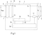
- the figure 1 shows an example of a power supply system with an electronic power supply device 1, at the output terminals 2, 3, a low-voltage load 4, which is symbolically represented by a resistor, is connected.
- a protective device 5 is connected in series with the low-voltage load 4, in the present example an electromagnetic circuit breaker.
- the electronic power supply device 1 provides, for example, a DC voltage U A of 24 V in nominal operation and a DC output current I L .
- a DC voltage U A of 24 V in nominal operation and a DC output current I L .
- several loads can of course be connected to the electronic power supply device 1, preferably in parallel. Each load can then be assigned its own circuit breaker.
- the electronic power supply device 1 can be a switched-mode power supply that is supplied at two input terminals 6, 7 via a mains voltage U mains .
- the power supply device 1 contains a rectifier circuit 8 associated with the input terminals 6, 7 and a power factor correction filter circuit 9, also known as a PFC or power factor conditioning circuit.
- the rectified input voltage is fed to the input terminals 12, 13 of a DC voltage converter 11, also known as a DC/DC converter, via an internal HV-DC bus.
- the DC/DC converter 11 converts the high input voltage, which is 300V DC, for example, into the required lower output voltage of 24V DC, and the DC/DC converter 11 provides the output direct current IL required at the output terminals 2, 3.
- a half-bridge LLC resonant converter is used as the DC/DC converter 11 in the present example.
- the working principle, physical properties and functioning of a half-bridge LLC resonant converter is known, for example from Bob Yang, Fred C. Lee, Alpha J. Zhang, Guisong Huang, LLC resonant Converter for Front End DC/DC Conversion, published on the Internet at http://www.cpes.vt.edu/_media/annual_reports/2002/Report /VolumeIIPartI/1DPS/4.p df .
- the DC/DC converter contains a converter setting device 16, by means of which setting values for the maximum direct current I L made available to the converter 11 at its converter output terminals 14, 15 are transmitted to the converter.
- the energy transmission ratio of the DC-DC converter between its input terminals 12, 13 and its output terminals 14, 15 can thus be adjusted to a certain extent.
- the power supply device 1 includes a current measuring device 17, which detects the output direct current I L provided by the DC/DC converter.
- the current measuring device 17 can be a current sensor known in principle, for example a measuring resistor across which the voltage drop is measured, which is proportional to the current flowing through the measuring resistor, or an inductive current sensor or a Hall sensor etc. This value is made available to a control logic 18 .
- the control logic 18 determines two manipulated variables for the converter actuating device 16 from the detected output current I L , its magnitude and its time profile.
- a second manipulated variable 20 causes the current provided by the DC/DC converter to be limited to a current peak value that corresponds to the maximum thermal peak load capacity of the components, in this example a value equal to six times the rated current, ie 60A
- the second manipulated variable thus causes a load connected to the output terminals 2, 3 of the power supply device to be able to "draw" a current up to the limit of 60A, depending on its size.
- the load 4 is, for example, 1.6 ohms in a first load state, then with an output voltage of 24V the switched-mode power supply 1 would provide an output current I L of 15A if the second manipulated variable is fed to the converter actuating device 16 . If the load resistance 4 drops to 1.2 ohms, for example, then the output current I L provided increases to 20A. If the load resistance 4 drops further to 0.8 ohms, for example, the current provided increases to 30A.
- the output current provided could even increase to 60A.
- Such a low load resistance of 0.4 ohms or less can occur, for example, when a short circuit begins in the load circuit.
- the output voltage U A is then still at its nominal value of 24V, but the switching power supply 1 according to the invention provides an output current of 60A without delay, which can be sufficient to trigger the protective device 5 and thus switch off the short circuit.
- the control logic 18 is set up in such a way that the increased output current I L , when it exceeds the threshold value IN, cannot be provided indefinitely, but only for a shorter period of time, the so-called output current pulse duration t pulse here.
- the output current pulse duration is determined in the control logic 18 as a function of the magnitude of the output current I L . she is the shorter, the larger the output current I L required by the load 4 is.
- the control logic 18 of the converter actuating device 16 makes the first manipulated variable 19 available instead of the second manipulated variable 20, which then causes the DC/DC converter to only output an output current at the level of the threshold value, here in the example dem 1.5 times the rated current.
- the control logic can be constructed as an electronic hardware circuit. It can also be implemented in software; then the control logic comprises a microprocessor with an appropriately set up application program.
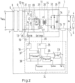
- the topology of the DC-DC converter 11 embodied as an LLC resonant converter is shown schematically here.
- the LLC resonant converter topology has three stages: a square wave generator 21, a resonant network 24, and a rectifier network 25.
- the square-wave generator 21 generates a square-wave voltage in that a control circuit 26 alternately controls two switches 22 and 23, implemented here as MOSFETs, with a pulse duty factor of 50%.
- the square wave generator 21 can be designed as a half bridge, as shown here, or as a full bridge.
- the resonant network 24 is formed with a capacitance 27, a series leakage inductance 28 and the magnetizing inductance 29 of a high-frequency transformer 30.
- FIG. The Q factor of the resonant network is influenced by these three components and the external load 4. The smaller the resistive component of the external load, and therefore the larger the output current demanded by the load at a constant output voltage, the larger the Q factor. In the event of a short circuit in the external load circuit, the resistance is very low, and the required output current and the Q factor of the resonant circuit 24 are correspondingly high. Likewise, during a heavy-duty start-up of an electric motor, the demanded output current and the Q-factor are high.
- the LLC resonant circuit 24 is operated in the area of zero voltage switching ZVS, that is to say the MOSFETs are switched over at the zero crossing of the voltage.
- the converter setting device ensures that operation in the area of zero current switching ZCS, which is also possible in principle, i.e. switching in the zero crossing of the current, is avoided.
- the LLC resonant circuit has two resonant frequencies, a first and a second resonant frequency.
- the second resonant frequency is lower than the first resonant frequency.
- the square wave generator is controlled so that the working frequency is kept close to the first resonant frequency.
- the gain of the LLC resonant circuit is almost independent of the external load, an advantage of the LLC topology.
- the converter setting device 16 influences the operating frequency of the LLC resonant circuit specified by the control circuit 26 of the square wave generator 21 by means of the setting variables 19 and 20 .
- the operating frequency of the LLC resonant circuit thus determines the maximum level of the output current for a given output DC voltage U A .
- the setting of the energy transfer ratio and thus the setting of the maximum direct current I L that can be called up by the DC/DC converter at its output terminals takes place via the setting of the oscillating circuit frequency of the LLC resonant converter.
- the rectifier network 25 rectifies the AC voltage present at the output of the HF transformer. It is designed here as a full-bridge rectifier 32 with a smoothing capacitor 31 .
- a first step 40 the power supply device 1 is adjusted to an output current up to a predetermined current peak value, if required to be able to provide the low-voltage load 4.
- the current peak value is six times the nominal current, with a 10A power pack this is 60A.
- the output voltage U a is 24V, and depending on the size of the load 4, this draws the required current, which can be less than the nominal current, but also greater.
- the power supply provides a current that is only limited by its own peak load capacity.
- the resulting brief current peak value corresponds to six times the nominal current.
- the resulting short-term current peak value can be so high that the protective device 5, here in the example an electromagnetic short-circuit current release, is reliably triggered.
- the output current I L provided by the electronic power supply device to the low-voltage load 4 is monitored to detect an increase in the output current I L above a threshold value I N that is lower than the current peak value.
- the threshold value I N is therefore set to 1.5 times the nominal current.
- the output current IL is recorded with the current measuring device 17, and the measured value is compared with the threshold value I N in a first comparison step 41.
- the electronic power supply device remains set to be able to provide an output current up to the predetermined current peak value to the low-voltage load 4, if required, until the output current I L becomes equal to or greater than the threshold value I N .
- a first comparison circuit 33 receives the measured value of the output current I L from the current measuring device 17 at its first input and the threshold value I N from a control circuit 34 at its second input. If the output current I L is less than the threshold value I N , an OR element 35 receives a logical 1 at one of its inputs, with the result that the output of the OR element 35 signals the converter actuating device 16 as a second manipulated variable 20 that the DC-DC converter 11 may provide the maximum output current I max if required.
- a first timer 36 is started.
- the first timer 36 receives from the control circuit 34 transmits a reference value for an output current pulse duration t pulses .
- the control circuit 34 has determined the output current pulse duration t Pulse as a function of the increased output current I L , as shown in the process diagram figure 3 this is the determination step 42.
- the dependence of the output current pulse duration t pulses on the increased output current, which is stored in the control circuit 34, is exemplified in FIG figure 4 shown.
- the first timer 36 sends a logical 1 to the input of the OR element 35, and the output of the OR element 35 signals as a second manipulated variable 20 to the converter setting device 16 that the DC-DC converter 11 may provide the maximum output current I max if required.
- the output current I L is provided at the level of the increased current value for the duration of the output current pulse duration determined.
- the second comparison step 43 it is determined when the output current pulse duration t pulses has been reached.
- the output of the NOR element 37 signals as the first manipulated variable 19 to the converter setting device 16 that the DC-DC converter 11 may only provide a maximum output current up to the level of the threshold value I N if required.
- This is the provision step 44 in the process flow figure 3 .
- a second timer 38 is started.
- the second timer 38 receives a reference value for a recovery time t recover from the control circuit 34 .
- the recovery time t recover is determined in the control circuit 34 as a function of the increased output current IL. The higher the output current, the longer the recovery time t recover , and the shorter the output current pulse duration t Pulse . In the figure 8 this relationship is shown as a representation of the ratio of output current pulse duration t pulse and recovery time t recover within the first second.
- a third comparison step 45 it is determined when the recovery time t recover has expired. If this has occurred, the OR element 35 receives a logical 1 at one of its inputs again, with the result that the output of the OR element 35 signals again as a second manipulated variable 20 to the converter actuating device 16 that the DC-DC converter 11 is at Need the maximum output current I max may provide. Further cycles can now follow, and the method can begin again at the first step 40 .
- control logic 18 All the functional blocks of the control logic 18 described can be implemented either in hardware as electronic circuits or in software as program modules of an application program for a microprocessor.
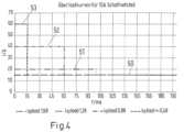
- the figure 4 shows a schematic representation of various overload curves in a 10A switched-mode power supply according to the invention.
- the figure 6 shows the output current pulse duration t Pulse in ms as a function of the increased output current I L as a multiple of the nominal current.
- the figure 8 shows the ratio of output current pulse duration and recovery time within the first second.
- the method according to the invention tries to carry out as many current pulses as possible within the first second, for example in order to optimally support the start-up processes of electric motors.
- curve 50 in figure 4 shows the case of a load 4 value of 1.6 ohms. With an output voltage of 24V, the resulting current of 15A can flow continuously. This corresponds to 1.5 times the nominal current; in figure 6 one sees that here the output current pulse duration is unlimited, in figure 8 you can see that here the duty cycle is 100%, so no recovery time is required.
- curve 51 in figure 4 shows the case of a load 4 value of 1.2 ohms. With an output voltage of 24V, the resultant current is 20A, which corresponds to twice the nominal current. In figure 6 you can see that the output current pulse duration is now 100ms figure 8 this results in a duty cycle of 50%, i.e. a recovery time of 100ms.
- curve 52 in figure 4 shows the case of a load 4 value of 0.8 ohms. With an output voltage of 24V, the resultant current is 40A, which corresponds to four times the nominal current. In figure 6 you can see that the output current pulse duration is now 60ms figure 8 this results in a duty cycle of 30%, i.e. a recovery time of 140ms.
- curve 53 in figure 4 shows the case of a value of the load 4 of 0.4 ohms, which can correspond to an incipient short circuit in the connected load circuit.
- the resulting current is 60A, which corresponds to 6 times the nominal current.
- the output current pulse duration is now 15ms figure 8 this results in a duty cycle of 7.5%, i.e. a recovery time of 185ms.
- the figure 5 shows possible output current pulse shapes when using the method according to the invention as a function of the load conditions.
- Curve 54 shows the case where there is a short circuit in the external load circuit, which could not be switched off, for example because the protective device did not respond for whatever reason.
- the output current pulse duration of 15ms determined at 6 times the nominal current see above, the output current is limited to 1.5 times the nominal current, for another 185ms, another output current pulse of 6 times the nominal current can then follow. In the figure 5 however, the other pulses are not shown.
- curve 55 in figure 5 shows the case where a short circuit in a downstream circuit was switched off by protective device 5 within 3 ms. Since other circuits are also connected that draw a low output current, the output current drops to a low value of around 9A in this example after the short circuit has been switched off.
- curve 56 in figure 5 shows the case of a heavy load that is switched on very quickly, corresponding to the curve 52 in figure 4 .
- the output current is increased to 60A depending on the load, as described above.
- the current is reduced to 1.5 times the nominal current, i.e. 15A.
- further pulses of 40 A and 60 ms duration can follow, if necessary until the heavy load condition no longer exists.
- the curve 57 in figure 5 shows the case of a heavy load that is slowly switched on.
- the output current is increased here slowly in a ramp shape until it has reached the maximum value corresponding to the maximum connected load, here in the example 50A, before the output current is limited to the threshold value of 15A, corresponding to 1.5 times the nominal value , sets in.
- the method according to the invention therefore provides that after an increased output current has been detected, the maximum duration of the output current pulse is determined as a function of the current actually flowing.
- the determination can be done either in hardware or in firmware.
- the output current is limited to the continuously supported output current to allow the components to recover.
- the cycles are kept as short as possible to ensure optimal start-up phases, e.g. with a starting motor as a load, while at the same time protecting internal components.
- the output capacitor 31 of the power pack 1 can support the initial current peak and thus protect internal components.
- the increased output current is made available by the power supply unit 1 before a special situation is detected, for example a short circuit, and not only as a reaction to a special situation that has been detected.
- the duration of the current pulses is not fixed, but is directly dependent on the transmitted power and is therefore adapted to the load.
- figure 7 shows the current pulses in an output voltage/output current diagram under various load conditions with loads that also have a high capacitive component. In the case of a large capacitive load, the output voltage collapses. Even under these load conditions, the method according to the invention generates a sequence of output current pulses with an increased output current value, the magnitude of the output current pulses being load-dependent and increasing as the load increases.
- the current pulse is aborted so that a system of power supplies connected in parallel does not oscillate.
Landscapes
- Engineering & Computer Science (AREA)
- Power Engineering (AREA)
- Dc-Dc Converters (AREA)
Description
- Die Erfindung betrifft ein Verfahren zur Energieversorgung einer Niederspannungslast mit Hilfe einer elektronischen Stromversorgungsvorrichtung.
- Die Erfindung betrifft weiterhin eine elektronische Stromversorgungsvorrichtung zur Energieversorgung einer Niederspannungslast durch Bereitstellen einer Ausgangsgleichspannung und eines Ausgangsstromes bis zur Höhe eines Stromspitzenwertes.
- In industriellen Anlagen werden Niederspannungsverbraucher, wie z.B. Steuerungen, Verstärker und dergleichen mit einer für den Menschen ungefährlichen Gleichspannung von vorzugsweise 24 Volt versorgt. Geeignete Stromversorgungseinrichtungen, die eine solche Gleichspannung bereitstellen, können Ausgangsströme von 20 A und mehr liefern. Bei derart hohen Strömen müssen Sicherungseinrichtungen, wie z.B. Schmelzsicherungen oder Leitungsschutzschalter, in Reihe mit den jeweiligen Verbrauchern geschaltet werden, um diese und insbesondere die Zuleitungen gegen thermische Überlastung und Kurzschlussströme zu sichern. Um Lei-tungsschutzschalter bei Auftritt eines elektrischen Störfalls, beispielsweise eines Kurzschlusses, sicher magnetisch auslösen zu können, sind Auslöseströme erforderlich, die etwa das 7,5-fache des hinsichtlich der Stromversorgungseinrichtung angegebenen Nennstroms betragen. Das Auslöseverhalten von Leitungsschutzschaltern ergibt sich aus deren Zeit-Strom-Auslösekennlinie, wie zum Beispiel der B-Charakteristik. Klassische 50 Hz-Transformator, die als Stromversorgungseinrichtungen verwendet werden, können bei üblicher Dimensionierung in einem Kurzschlussfall derart hohe Auslöseströme für Leitungsschutzschalter liefern. Aufgrund hoher elektrischer Verluste und des großen Gewichtes werden derartige 50 Hz-Transformatoren in der Industriestromversorgung immer häufiger durch elektronische Stromversorgungseinrichtungen, wie z.B. mit hoher Frequenz getakteter Schaltnetzteile ersetzt. Elektronische Stromversorgungseinrichtungen begrenzen jedoch üblicherweise den Ausgangsstrom bei Auftritt einer elektrischen Störung sehr schnell, das heißt zwischen 10 und 100 µsec, auf den 1,1- bis 1,5-fachen Wert des Nenn-stroms, um Verbraucher und Zuleitungen gegen thermische Überlastungen und Kurzschlussströme zu schützen. Damit ist ein sicheres Auslösen einer elektromagnetischen Schutzeinrichtung nicht immer gewährleistet.
- Ein ausgangsseitiger erhöhter Energiebedarf tritt nicht nur bei einer Störung, wie dem erwähnten Kurzschluss, auf. Auch das Zuschalten von Lasten, beispielsweise der Anlauf eines Elektromotors, kann einen kurzfristig erhöhten Energiebedarf an der Ausgangsseite der Stromversorgungseinrichtung zur Folge haben. In diesem Fall würde man allgemein von einer Sonderbedingung mit erhöhtem Energiebedarf sprechen. Ein Störfall wie der erwähnte Kurzschluss ist eine extreme Ausprägung einer solchen Sonderbedingung.
- Beim Zuschalten einer großen kapazitiven Last bricht die Ausgangsspannung schnell ein, und sie steigt als Funktion des Schleifenwiderstandes und der Kapazität wieder an. Beim Zuschalten einer induktiv-ohmschen Last, etwa eines Motors, fließt ein hoher Anlaufstrom, der nur durch den ohmschen Widerstand der Motorwicklung begrenzt wird. Üblicherweise wird innerhalb weniger Sekunden der Normalbetrieb wieder erreicht. In der Übergangszeit kann die Last von der Stromversorgungseinrichtung allerdings Ausgangsströme ziehen, die weit über dem 1,5-fachen Wert, aber unterhalb des für das Auslösen der Sicherungseinrichtung erforderlichen 6- bis 7,5-fachen Wert des Nennstroms liegen, und das für eine variable, lastabhängige und nicht vorherbestimmbare Zeitdauer.
- Aus der
DE 10 2005 031 833 A1 ist ein Verfahren zur Energieversorgung einer durch eine Schutzeinrichtung gesicherten Niederspannungslast mit Hilfe einer elektronischen Stromversorungsvorrichtung, eines Schaltnetzteils, bekannt, nach dem die Eingangs- und/oder Ausgangsspannung der Stromversorgungseinrichtung überwacht wird, um einen Abfall der Eingangs- und/oder Ausgangsspannung unter einen Schwellwert zu erfassen. Beim Erfassen eines Abfalls der Ein- und/oder Aus-gangsspannung unter den Schwellwert wird ein Strom für eine vorbestimmte Zeit bereitgestellt, dessen Größe derart bemessen wird, dass die Schutzeinrichtung sicher ausgelöst wird, und nach Ablauf der vorbestimmten Zeit wird der Strom auf einen niedrigeren Wert begrenzt. Im Stand der Technik wird ein Abfall der Ein- oder Ausgangsspannung unter einen Schwellwert als Indiz für einen Störfall oder einer Sondersituation interpretiert, und in Reaktion darauf ein erhöhter Ausgangsstrom bereitgestellt, der immer so hoch ist, dass eine Schutzeinrichtung sicher ausgelöst werden kann. - Damit ist ein an die spezifische Art eines Störfalls oder einer Sonderbedingung angepasstes Reagieren der Stromversorgungsvorrichtung nicht möglich. Der Stand der Technik unterscheidet nicht, ob die Sonderbedingung beispielsweise ein Kurzschluss oder ein Motoranlauf ist.
- Die
WO 2015082207 A1 zeigt eine Stromversorgungseinrichtung zum Umwandeln einer Eingangsspannung in eine Ausgangsspannung, aufweisend zumindest eine von einer Pulsweitenmodulationsschaltung getaktet angesteuerten Schaltstufe, wobei eine Regelschaltung vorgesehen ist, die auf die Pulsweitenmodulationsschaltung zur Änderung der Höhe der Ausgangsspannung einwirkt, wobei eine Strombegrenzungsschaltung vorgesehen ist, die einen Ausgangsstrom der Stromversorgungseinrichtung nach Überschreiten eines Schwellenwertes zunächst für einen Zeitraum auf einen erhöhten Maximalstrom begrenzt und danach auf einen regulären Maximalstrom begrenzt, wobei die Regelschaltung so eingerichtet ist, dass der Zeitraum, für den der Ausgangsstrom auf den erhöhten Maximalstrom begrenzt ist, von der Höhe des Ausqanqsstroms abhängig ist, sowie ein entsprechendes Verfahren. - Es ist daher die der vorliegenden Erfindung zugrundeliegende Aufgabe, ein Verfahren zur Energieversorgung einer Niederspannungslast mit Hilfe einer elektronischen Stromversorgung zu schaffen, das in Reaktion auf das Auftreten einer Sonderbedingung im nachgeordneten Stromkreis einen erhöhten Ausgangsstrom schnell und angepasst an die aus der Art der Sonderbedingung sich ergebenden Erfordernisse bereitstellt.
- Es ist eine weitere Aufgabe der vorliegenden Erfindung, eine elektronische Stromversorgungsvorrichtung zur Energieversorgung einer Niederspannungslast durch Bereitstellen einer Ausgangsgleichspannung und eines Ausgangsstromes zu schaffen, mit der das erfindungsgemäße Verfahren durchgeführt werden kann.
- Die Aufgabe wird bezüglich des Verfahrens gelöst durch ein Verfahren nach Anspruch 1.
- Bezüglich der elektronischen Stromversorgungsvorrichtung wird die Aufgabe gelöst durch eine elektronische Stromversorgungsvorrichtung nach Anspruch 5.
- Der vorbestimmte Stromspitzenwert entspricht der Spitzenbelastbarkeit der Stromversorgungsvorrichtung. Bei einem schaltnetzteil ist das beispielsweise der 6-fache Nennstrom. Ein 10A-Netzteil zum Beispiel hat dann eine Spitzenbelastbarkeit von 60A.
- Erfindungsgemäß also kann die Stromversorgungsvorrichtung von Anfang an bei Bedarf einen Ausgangsstrom liefern der dem Stromspitzenwert entspricht. Es gibt keine anfängliche Strombegrenzung auf den 1,5 - fachen Nennstrom, wie es bei Schaltnetzteilen im Stand der Technik vorgesehen und bekannt ist. Der Vorteil liegt darin, dass bei Auftreten einer Sondersituation, beispielsweise des Anlaufens eines Motors, wenn die Last einen Ausgangsstrom des Schaltnetzteiles benötigt, der größer als der 1,5-fache Nennstrom ist, also beispielsweise 30A, dieser erhöhte Strom unmittelbar und verzögerungsfrei zur Verfügung gestellt wird.
- Durch das erfindungsgemäße Merkmal b) wird eine Sondersituation erkannt, indem der Ausgangsstrom gemessen wird. Der Schwellwert liegt beispielsweise bei einem Ausgangsstrom vom 1,5 - fachen des Nennwertes, bei einem 10A-netzteil beispielsweise bei 15A. wenn also die angeschlossene Last einen Strom von mehr als 15A "zieht", heißt das, dass eine Sondersituation, beispielsweise ein Motoranlauf oder ein Kurzschluss im angeschlossenen Stromkreis vorliegt. Die Erkennung der Sondersituation anhand des Stromverlaufs hat den Vorteil, dass auch Sondersituationen erfasst werden, bei denen die Ausgangsspannung anfänglich nicht absinkt, wie es beispielsweise bei einer induktiven oder resistiven Last, wie bei dem Motoranlauf, der Fall ist. Außerdem wird eine Sondersituation über die Messung des Ausgangsstromes schneller erfasst als mit Messung der Ausgangsspannung, denn der Stromanstieg erfolgt zeitlich vor dem Absinken der Ausgangsspannung.
- Die Merkmale c) und d) sorgen dafür, dass der Ausgangsstrom in der Höhe, wie er von der Last in der Sondersituation gerade benötigt wird, bereitgestellt ist, und zwar für eine Impulsdauer, die an die Höhe des geforderten Ausgangsstromes angepasst ist. Das ist in vorteilhafter Weise eine lastbezogene Strombereitstellung.
- In einer vorteilhaften Weiterbildung ist die Ausgangsstrompulsdauer dabei umso länger, je niedriger der erhöhte Ausgangsstromwert ist.
- Um eine Überlastung des Netzteiles zu vermeiden, wird erst nach Ablauf der lastbezogen ermittelten Impulsdauer der Ausgangsstrom auf den Schwellwert, also beispielsweise den 1,5-fachen Nennstrom, begrenzt.
- Erfindungsgemäß erfolgt das Bereitstellen des Ausgangsstromes in Höhe des Schwellwertes nach Ablauf der Ausgangsstrompulsdauer für die Dauer einer vorbestimmten Erholungszeit, und nach Ablauf der Erholungszeit wird die Stromversorgungsvorrichtung wieder darauf eingestellt, um bei Bedarf einen Ausgangsstrom bis zu dem vorbestimmten Stromspitzenwert an die Niederspannungslast bereitstellen zu können. Damit verbunden ist der Vorteil, dass die Komponenten des Netzteiles sich während der Erholungszeit abkühlen können, und falls die Sondersituation nach Ende der Erholungszeit noch nicht abgeklungen sein sollte, der erhöhte Ausgangsstrom erneut für die Dauer einer Ausgangsstrompulsdauer zur Verfügung gestellt wird, und so weiter, bis die Sondersituation behoben ist. Das beheben der Sondersituation kann beispielsweise im Falle des Motoranlaufs darin bestehen, dass der Motor seinen Nenndrehzahl erreicht hat, oder im Falle eines Kurzschlusses darin, dass die Sicherungseinrichtung angesprochen hat und der entsprechende Stromkreis abgeschaltet wurde.
- Erfindungsgemäß wird die Erholungszeit in Abhängigkeit von dem erhöhten Ausgangsstromwert ermittelt. Damit verbunden ist der Vorteil, dass die Erholungszeit an die Last während der Sonderbedingung angepasst ist und das Verfahren damit sehr flexibel auf die jeweils tatsächlich vorliegenden Lastbedingungen reagieren kann. Im Falle eines Kurzschlusses beispielsweise mit dem maximal möglichen Ausgangsstrom muss die Erholungszeit länger sein als bei einem Motoranlauf mit geringfügig erhöhtem Strombedarf von beispielsweise dem 2-fachen Nennstrom. Hier kann die Erholungszeit kürzer sein, so dass insgesamt die Zeitdauer der Sonderbedingung verkürzt wird.
- Wenn gemäß einer vorteilhaften Ausführungsform der Erfindung eine Schutzeinrichtung zur Sicherung der Niederspannungslast vorhanden ist, beispielsweise ein Leitungsschutzschalter mit einem elektromagnetischen Kurzschlussstromauslöser, dann wird der Stromspitzenwert so hoch bestimmt, dass die Schutzeinrichtung sicher ausgelöst wird, und zwar bevorzugt innerhalb einer Zeit, die kleiner ist als die Ausgangsstrompulsdauer.
- In einer vorteilhaften Weiterbildung der Erfindung wird, wenn der Ausgangsstrom vor Ablauf der Ausgangsstrompulsdauer den Schwellwert erreicht oder unterschreitet, die Stromversorgungsvorrichtung darauf eingestellt, um einen Ausgangsstrom bis zur Höhe des Schwellwertes bereitstellen zu können. Das bedeutet, dass nach dem Unterschreiten des Schwellwertes, also beispielsweise des 1,5-fachen Nennwertes des Ausgangsstromes, der aktuelle Strompuls abgebrochen wird, denn dann ist die Sondersituation offensichtlich beendet und es besteht keine Veranlassung, den erhöhten Stromwert bis zum Ende der Ausgangsstrompulsdauer weiter zur Verfügung zu stellen. Durch diese Maßnahme wird verhindert, dass es im Falle dass ein System mehrerer parallel geschalteter Stromversorgungen vorhanden ist, es zum Schwingen dieses Systems kommen kann.
- Eine erfindungsgemäße elektronische Stromversorgungsvorrichtung ist in einer vorteilhaften Ausgestaltung ein elektronisches Schaltnetzteil, und die Einrichtung hat einen Gleichspannungswandler mit einstellbarem Energieübertragungsverhältnis und eine Strommesseinrichtung zur Überwachung des Ausgangsstromes und eine Einstelleinrichtung zur Einstellung des Energieübertragungsverhältnisses in Abhängigkeit von dem erfassten Ausgangsstrom. Der Gleichspannungswandler ist dabei in einer vorteilhaften Ausführungsform ein Halbbrücken-LLC-Resonanzwandler.
- In vorteilhafter Ausführungsform der Erfindung beeinflusst die Einstelleinrichtung zur Einstellung des Energieübertragungsverhältnisses die Arbeitsfrequenz des Halbbrücken-LLC-Resonanzwandlers.
- Die Erfindung wird nachfolgend anhand eines Ausführungsbeispiels in Verbindung mit den beiliegenden Zeichnungen näher erläutert.
- Es zeigen
- Fig. 1
- schematisch eine Vorrichtung zur Energieversorgung einer Niederspannungslast gemäß der Erfindung,
- Fig. 2
- schematisch eine weitere Ausführungsform einer Energieversorgungeiner Niederspannungslast gemäß der Erfindung,
- Fig. 3
- ein Ablaufschema des erfindungsgemäßen Verfahrens zur Energieversorgung einer Niederspannungslast gemäß der Erfindung,
- Fig. 4
- eine schematische Darstellung verschiedener Überlastkurven bei einem erfindungsgemäßen Schaltnetzteil;
- Fig. 5
- eine schematische Darstellung verschiedener Ausgangsstrompulse gemäß dem erfindungsgemäßen Verfahren bei verschiedenen Lastbedingungen,
- Fig. 6
- eine Darstellung der Ausgangsstrompulsdauer in Abhängigkeit von dem erhöhten Stromwert gemäß einer Ausführungsform des erfindungsgemäßen Verfahrens,
- Fig. 7
- eine Darstellung der Strompulse im Ausgangs-Spannungs/AusgangsStrom - Diagramm gemäß dem erfindungsgemäßen Verfahren bei verschiedenen Lastbedingungen
- Fig. 8
- das Verhältnis von Ausgangsstrom-Pulsdauer und Erholungszeit innerhalb der ersten Sekunde gemäß einer Ausführungsform des erfindungsgemäßen Verfahrens.
- Die
Figur 1 zeigt beispielhaft ein Energieversorgungssystem mit einer elektronischen Stromversorgungsvorrichtung 1, an deren Ausgangsklemmen 2, 3 eine Niederspannungslast 4, die symbolisch durch einen Widerstand dargestellt ist, angeschaltet ist. In reihe mit der Niederspannungslast 4 ist eine Schutzeinrichtung 5 geschaltet, im hier vorliegenden Beispiel ein elektromagnetischer Leitungsschutzschalter. - Die elektronische Stromversorgungseinrichtung 1 stellt an ihren Ausgangsklemmen 2, 3 beispielsweise eine Gleichspannung UA von 24V im Nennbetrieb und einen Ausgangsgleichstrom IL bereit. Obwohl in
Figur 1 nur eine Niederspannungslast 4 an die elektronische Stromversorgungseinrichtung 1 angeschlossen ist, können natürlich mehrere Lasten, vorzugsweise parallel, an die elektronische Stromversorgungseinrichtung 1 angeschlossen werden. Jeder Last kann dann ein eigener Leitungsschutzschalter zugeordnet sein. - Bei der elektronischen Stromversorgungseinrichtung 1 kann es sich um ein Schaltnetzteil handeln, das an zwei Eingangsklemmen 6, 7 über eine Netzspannung UNetz versorgt wird. Die Stromversorgungseinrichtung 1 enthält eine den Eingangsklemmen 6, 7 zugeordnete Gleichrichterschaltung 8 und eine Leistungsfaktorkorrekturfilter-Schaltung 9, auch bekannt als PFC oder Power Factor Conditioning-Schaltung. Über einen internen HV-DC-Bus wird die gleichgerichtete Eingangsspannung den Eingangsklemmen 12, 13 eines Gleichspannungswandlers 11, auch als DC/DC-Wandler bekannt, zugeführt. Der DC/DC-Wandler 11 wandelt die hohe Eingangsspannung, die beispielsweise 300V DC beträgt, in die geforderte niedrigere Ausgangsspannung von 24V DC, und der DC/DC-Wandler 11 stellt den an den Ausgangsklemmen 2, 3 geforderten Ausgangsgleichstrom IL bereit.
- Im vorliegenden Beispiel wird als DC/DC-Wandler 11 ein Halbbrücken-LLC-Resonanzwandler verwendet. Das Arbeitsprinzip, die physikalischen Eigenschaften und die Funktionsweise eines Halbbrücken-LLC-Resonanzwandlers ist bekannt, beispielsweise aus Bob Yang, Fred C. Lee, Alpha J. Zhang, Guisong Huang, LLC resonant Converter for Front End DC/DC Conversion, veröffentlicht im Internet unter http://www.cpes.vt.edu/_media/annual_reports/2002/Report/VolumeIIPartII/1DPS/4.p df. Der DC/DC-Wandler beinhaltet eine Wandler-Stelleinrichtung 16, mittels derer dem Wandler 11 Stellwerte für den maximal von ihm an dessen Wandlerausgangsklemmen 14, 15 zur Verfügung gestellten Gleichstrom IL übermittelt werden. Damit ist gewissermaßen das Energieübertragungsverhältnis des Gleichspannungswandlers zwischen seinen Eingangsklemmen 12, 13 und seinen Ausgangsklemmen 14, 15 einstellbar.
- Die Stromversorgungseinrichtung 1 beinhaltet eine Strommesseinrichtung 17, die den von dem DC/DC-Wandler bereitgestellten Ausgangsgleichstrom IL erfasst. Die Strommesseinrichtung 17 kann ein im Prinzip bekannter Stromsensor sein, zum Beispiel ein Messwiderstand, über dem der Spannungsabfall gemessen wird, welcher proportional zu dem durch den Messwiderstand fließenden Strom ist, oder ein induktiv arbeitender Stromsensor oder ein Hall-Sensor etc. Dieser Wert wird einer Steuerlogik 18 zur Verfügung gestellt. Die Steuerlogik 18 ermittelt aus dem erfassten Ausgangsstrom IL, aus dessen Höhe und dessen zeitlichem Verlauf, zwei Stellgrößen für die Wandler-Stelleinrichtung 16. Eine erste Stellgröße bewirkt, dass der von dem DC/DC-Wandler bereitgestellte Strom auf einen Schwellwert IN, der beispielsweise dem 1,5-fachen Nennstrom von hier im Beispiel 1,5 x 10A = 15A entspricht, begrenzt ist. Eine zweite Stellgröße 20 bewirkt, dass der von dem DC/DC-Wandler bereitgestellt Strom auf einen Stromspitzenwert begrenzt ist, der der maximalen thermischen Spitzenbelastbarkeit der Bauelemente entspricht, hier im Beispiel ein Wert in Höhe des sechsfachen Nennstroms, also 60A.
- Die zweite Stellgröße bewirkt also, dass eine an den Ausgangsklemmen 2, 3 der Stromversorgungseinrichtung angeschlossene Last in Abhängigkeit von ihrer Größe einen Strom bis zur Grenze von 60A "ziehen" kann. Wenn die Last 4 in einem ersten Lastzustand beispielsweise 1,6 Ohm beträgt, so würde bei einer Ausgangsspannung von 24V das Schaltnetzteil 1 einen Ausgangsstrom IL von 15A bereitstellen, wenn die zweite Stellgröße der Wandler-Stellleinrichtung 16 zugeführt ist. Sinkt der Lastwiderstand 4 auf beispielsweise 1,2 Ohm, so erhöht sich der bereitgestellt Ausgangsstrom IL auf 20A. Sinkt der Lastwiderstand 4 weiter auf beispielsweise 0,8 Ohm, so steigt der bereitgestellte Strom auf 30A. Bei einem angenommenen weiteren Absinken des Lastwiderstandes auf 0,4 Ohm würde der bereitgestellte Ausgangsstrom sogar auf 60A ansteigen können. Ein so niedriger Lastwiderstand von 0,4 Ohm oder weniger kann beispielsweise bei einem beginnenden Kurzschluss in dem Lastkreis auftreten. Die Ausgangsspannung UA ist dann noch auf ihrem Nennwert von 24V, doch das erfindungsgemäße Schaltnetzteil 1 stellt ohne Verzögerung einen Ausgangsstrom von 60A zur Verfügung, der ausreichen kann, um die Schutzeinrichtung 5 auszulösen und den Kurzschluss damit abzuschalten.
- Die Steuerlogik 18 ist jedoch so eingerichtet, dass der erhöhte Ausgangsstrom IL , wenn er den Schwellwert IN überschreitet, nicht unbegrenzt lange bereitgestellt werden kann, sondern nur für eine kürzere Zeitdauer, die hier sogenannte Ausgangsstrompulsdauer tpulse. Die Ausgangsstrompulsdauer wird in Abhängigkeit von der betragsmäßigen Höhe des Ausgangsstromes IL in der Steuerlogik 18 ermittelt. Sie ist umso kürzer, je größer der von der Last 4 geforderte Ausgangsstrom IL ist. Wenn die Ausgangsstrompulsdauer erreicht ist, stellt die Steuerlogik 18 der Wandler-Stelleinrichtung 16 statt der zweiten Stellgröße 20 die erste Stellgröße 19 zur Verfügung, welche dann bewirkt, dass der DC/DC-Wandler nur einen Ausgangsstrom in Höhe des Schwellwertes von hier im Beispiel dem 1,5-fachen Nennstrom bereitstellt.
- Die Steuerlogik kann als elektronische Hardwareschaltung aufgebaut sein. Sie kann auch in Software realisiert sein; dann umfasst die Steuerlogik einen Mikroprozessor mit einem entsprechend eingerichteten Anwendungsprogramm.
- Es werde nun die
Figur 2 betrachtet. Hier ist schematisch die Topologie des als LLC-Resonanzwandler ausgeführten Gleichspannungswandlers 11 gezeigt. Die Topologie des LLC-Resonanzwandlers hat drei Stufen: einen Rechteckwellengenerator 21, ein Resonanznetzwerk 24 und ein Gleichrichternetzwerk 25. - Der Rechteckwellengenerator 21 erzeugt eine Rechteckspannung, indem eine Steuerschaltung 26 zwei hier als MOSFETs realisierte Schalter 22 und 23 abwechselnd mit einem Tastverhältnis von 50% ansteuert. Der Rechteckwellengenerator 21 kann als Halbbrücke, wie hier gezeigt, oder als Vollbrücke ausgebildet sein.
- Das Resonanznetzwerk 24 ist mit einer Kapazität 27, einer Serien-Streuinduktivität 28 und der Magnetisierungsinduktivität 29 eines Hochfrequenztransformators 30 ausgebildet. Der Q-Faktor des Resonanznetzwerkes wird von diesen drei Komponenten und der externen Last 4 beeinflusst. Je kleiner der ohmsche Anteil der externen Last, und je größer deshalb der bei konstanter Ausgangsspannung von der Last angeforderte Ausgangsstrom, desto größer ist der Q-Faktor. Bei einem Kurzschluss im externen Lastkreis ist der Widerstand sehr klein, entsprechend ist der angeforderte Ausgangsstrom und der Q-Faktor des Resonanzkreises 24 hoch. Ebenso ist bei einem Schwerlastanlauf eines Elektromotors der angeforderte Ausgangsstrom und der Q-Faktor hoch. Der LLC-Resonanzkreis 24 wird in der hier beschriebenen Anwendung im Bereich des Zero Voltage Switching ZVS betrieben, das heißt, das Umschalten der MOSFETs erfolgt im Nulldurchgang der Spannung. Die Wandler-Stelleinrichtung sorgt dafür, dass der prinzipiell ebenfalls mögliche Betrieb im Bereich des Zero Current Switching ZCS, also Schalten im Nulldurchgang des Stromes, vermieden wird. Der LLC-Resonanzkreis hat zwei Resonanzfrequenzen, eine erste und eine zweite Resonanzfrequenz. Die zweite Resonanzfrequenz ist kleiner als die erste Resonanzfrequenz. Der Rechteckwellengenerator wird so gesteuert, dass die Arbeitsfrequenz in der Nähe der ersten Resonanzfrequenz gehalten wird. Hier ist die Verstärkung des LLC-Resonanzkreises nahezu unabhängig von der äußeren Last, ein Vorteil der LLC-Topologie. Durch Veränderung der Arbeitsfrequenz weg von der ersten Resonanzfrequenz kann die Verstärkung des LLC-Resonanzkreises und damit die übertragene Energie beziehungsweise der am Ausgang bereitstellbare Ausgangsstrom beeinflusst werden. Die Wandler-Stelleinrichtung 16 beeinflusst mittels der Stellgrößen 19 und 20 daher die von der Steuerschaltung 26 des Rechteckwellengenerators 21 vorgegebene Arbeitsfrequenz des LLC-Resonanzkreises. Die Arbeitsfrequenz des LLC-Resonanzkreises legt damit die maximale Höhe des Ausgangsstromes bei einer gegebenen Ausgangsgleichspannung UA fest. Vereinfacht ausgedrückt erfolgt die Einstellung des Energieübertragungsverhältnisses und damit die Einstellung des von dem DC/DC-Wandler an seinen Ausgangsklemmen maximal abrufbaren Geleichstromes IL über die Einstellung der Schwingkreis-Frequenz des LLC-Resonanzwandlers.
- Das Gleichrichternetzwerk 25 richtet die am Ausgang des HF-Transformators anstehende Wechselspannung wieder gleich. Sie ist hier als Vollbrückengleichrichter 32 mit Glättungskondensator 31 ausgeführt.
- Es werde nun die
Figur 3 betrachtet. Hier wird das erfindungsgemäße Verfahren zur Energieversorgung einer Niederspannungslast 4 mit Hilfe einer elektronischen Stromversorgungsvorrichtung 1 erläutert, wie es mit der elektronischen Stromversorgungsvorrichtung 1 gemäß denFiguren 1 und2 durchgeführt werden kann. Bei der Beschreibung des erfindungsgemäßen Verfahrens nachFigur 3 wird auch Bezug genommen auf eine exemplarische Implementierung dieser Verfahrensschritte in der Steuerlogik 18. Dazu ist in derFigur 2 innerhalb der Steuerlogik 18 lediglich beispielhaft und schematisch eine mögliche Anordnung und Verknüpfung von Funktionsbausteinen, teils Zähler, teils logische Gatter, teils komplexere Kontrollschaltungsglieder, dargestellt. Die tatsächliche Realisierung des erfindungsgemäßen Verfahrens in einer elektronischen Schaltung oder mithilfe einer Anwendungssoftware für einen Mikroprozessor kann auch davon abweichende, anders aufgebaute und/oder anders zusammengestellte Funktionsbausteine oder Programmmodule umfassen und enthalten. - In einem ersten Schritt 40 wird die Stromversorgungseinrichtung 1 darauf eingestellt, um bei Bedarf einen Ausgangsstrom bis zu einem vorbestimmten Stromspitzenwert an die Niederspannungslast 4 bereitstellen zu können. Der Stromspitzenwert ist im oben beschriebenen Beispiel der sechsfache Nennstrom, bei einem 10A - Netzteil sind das 60A. Die Ausgangsspannung Ua beträgt 24V, und je nach der Größe der Last 4 zieht diese den erforderlichen Strom, welcher geringer als der Nennstrom sein kann, aber auch größer. Das Netzteil stellt einen Strom zur Verfügung, der nur durch die eigene Spitzenbelastbarkeit begrenzt wird. Der resultierende kurzzeitige Stromspitzenwert entspricht dem sechsfachen Nennstrom. Der resultierende kurzzeitige Stromspitzenwert kann dabei so hoch sein, dass die Schutzeinrichtung 5, hier im Beispiel ein elektromagnetischer Kurzschlussstromauslöser, sicher ausgelöst wird.
- Der von der elektronischen Stromversorgungseinrichtung an die Niederspannungslast 4 bereitgestellte Ausgangsstrom IL wird überwacht, um ein Ansteigen des Ausgangsstroms IL über einen Schwellwert IN, der niedriger ist als der Stromspitzenwert, zu erkennen. Dauerhaft kann das Netzteil abhängig von der Umgebungstemperatur und der Einbaulage den 1,5 - fachen Nennstrom liefern zur Unterstützung länger anhaltender Überlastphasen. Der Schwellwert IN wird daher auf den 1,5 - fachen Nennstrom eingestellt. Der Ausgangsstrom IL wird mit der Strommesseinrichtung 17 erfasst, der Messwert wird in einem ersten Vergleichsschritt 41 mit dem Schwellwert IN verglichen. Ist der Ausgangsstrom IL kleiner als der Schwellwert IN, so wird weiter gemessen und verglichen und die elektronische Stromversorgungseinrichtung bleibt darauf eingestellt, um bei Bedarf einen Ausgangsstrom bis zu dem vorbestimmten Stromspitzenwert an die Niederspannungslast 4 bereitstellen zu können, so lange, bis der Ausgangsstrom IL gleich oder größer als der Schwellwert IN wird.
- In der
Figur 2 sind dazu schematisch und lediglich beispielhaft mögliche Funktionsblöcke innerhalb der Steuerlogik 18 dargestellt. Eine erste Vergleichsschaltung 33 erhält an ihrem ersten Eingang den Messwert des Ausgangsstromes IL von der Strommesseinrichtung 17, an ihrem zweiten Eingang den Schwellwert IN von einer Kontrollschaltung 34 zur Verfügung gestellt. Ist der Ausgangsstrom IL kleiner als der Schwellwert IN, so erhält ein ODER-Glied 35 an einem seiner Eingänge eine logische 1, was zur Folge hat, dass der Ausgang des ODER-Gliedes 35 als zweite Stellgröße 20 der Wandler-Stelleinrichtung 16 signalisiert, dass der Gleichspannungswandler 11 bei Bedarf den maximalen Ausgangsstrom Imax bereitstellen darf. - Wird hingegen der Ausgangsstrom IL gleich oder größer als der Schwellwert IN, so wird ein erster Timer 36 gestartet. Der erste Timer 36 erhält von der Kontrollschaltung 34 einen Referenzwert für eine Ausgangsstrompulsdauer tPulse übermittelt. Die Kontrollschaltung 34 hat die Ausgangsstrompulsdauer tPulse in Abhängigkeit von dem erhöhten Ausgangsstrom IL ermittelt, im Verfahrensschema nach
Figur 3 ist das der Ermittlungsschritt 42. Die in der Kontrollschaltung 34 hinterlegte Abhängigkeit der Ausgangsstrompulsdauer tPulse von dem erhöhten Ausgangsstrom ist beispielhaft in derFigur 4 dargestellt. Solange wie die Ausgangsstrompulsdauer tPulse nicht erreicht ist, gibt der erste Timer 36 eine logische 1 an den Eingang des ODER-Gliedes 35, und der Ausgang des ODER-Gliedes 35 signalisiert als zweite Stellgröße 20 der Wandler-Stelleinrichtung 16, dass der Gleichspannungswandler 11 bei Bedarf den maximalen Ausgangsstrom Imax bereitstellen darf. Der Ausgangsstrom IL wird in der Höhe des erhöhten Stromwertes für die Dauer der ermittelten Ausgangsstrompulsdauer bereitgestellt. - In dem zweiten Vergleichsschritt 43 wird ermittelt, wann die Ausgangsstrompulsdauer tPulse erreicht ist. Wenn diese eingetreten ist, geschieht zweierlei. Der Ausgang des NOR-Gliedes 37 signalisiert als erste Stellgröße 19 der Wandler-Stelleinrichtung 16, dass der Gleichspannungswandler 11 bei Bedarf nur noch einen maximalen Ausgangsstrom bis zur Höhe des Schwellenwertes IN bereitstellen darf. Dies ist der Bereitstellungsschritt 44 im Verfahrensablauf nach
Figur 3 .Und es wird ein zweiter Timer 38 gestartet. Der zweite Timer 38 erhält von der Kontrollschaltung 34 einen Referenzwert für eine Erholungszeit trecover übermittelt. Die Erholungszeit trecover wird in der Kontrollschaltung 34 in Abängigkeit von dem erhöhten Ausgangsstrom IL ermittelt. Je höher der Ausgangsstrom, desto größer auch die Erholungszeit trecover , und desto kürzer war ja auch die Ausgangsstrompulsdauer tPulse. In derFigur 8 ist dieser Zusammenhang als Darstellung des Verhältnisses von Ausgangsstrom-Pulsdauer tPulse und Erholungszeit trecover innerhalb der ersten Sekunde dargestellt. - In einem dritten Vergleichsschritt 45 wird ermittelt, wann die Erholungszeit trecover abgelaufen ist. Ist dies eingetreten, so erhält das ODER-Glied 35 an einem seiner Eingänge wieder eine logische 1, was zur Folge hat, dass der Ausgang des ODER-Gliedes 35 wieder als zweite Stellgröße 20 der Wandler-Stelleinrichtung 16 signalisiert, dass der Gleichspannungswandler 11 bei Bedarf den maximalen Ausgangsstrom Imax bereitstellen darf. Es können nun weitere Zyklen folgen, das Verfahren kann wieder bei dem ersten Schritt 40 beginnen.
- Alle beschriebenen Funktionsblöcke der Steuerlogik 18 können entweder in Hardware als elektronische Schaltungen oder in Software als Programmmodule eines Anwendungsprogramms für einen Mikroprozessor ausgeführt sein.
- Es sollen jetzt die
Figuren 4 ,6 und8 zusammen betrachtet werden. DieFigur 4 zeigt als schematische Darstellung verschiedene Überlastkurven bei einem erfindungsgemäßen 10A-Schaltnetzteil. DieFigur 6 zeigt die Ausgangsstrompulsdauer tPulse in ms in Abhängigkeit des erhöhten Ausgangsstromes IL als Vielfaches des Nennstromes. DieFigur 8 zeigt das Verhältnis von Ausgangsstrom-Pulsdauer und Erholungszeit innerhalb der ersten Sekunde. Das erfindungsgemäße Verfahren versucht, innerhalb der ersten Sekunde möglichst viele Strompulse durchzuführen, um zum Beispiel Anlaufvorgänge von Elektromotoren optimal zu unterstützen. - Kurve 50 in
Figur 4 zeigt den Fall eines Wertes der Last 4 von 1,6 Ohm. Bei 24V Ausgangsspannung kann der resultierende Strom von 15A dauerhaft fließen. Das entspricht dem 1,5-fachen des Nennstromes; inFigur 6 sieht man, dass hier die Ausgangsstrompulsdauer unbegrenzt ist, inFigur 8 sieht man, dass hier das Tastverhältnis 100% ist, also keine Erholungszeit erforderlich ist. - Kurve 51 in
Figur 4 zeigt den Fall eines Wertes der Last 4 von 1,2 Ohm. Bei 24V Ausgangsspannung ergibt sich ein resultierender Strom von 20A, das entspricht dem 2-fachen des Nennstroms. InFigur 6 sieht man, dass jetzt die Ausgangsstrompulsdauer 100ms beträgt, ausFigur 8 ergibt sich dazu ein Tastverhältnis von 50%, also eine Erholungszeit von 100ms. - Kurve 52 in
Figur 4 zeigt den Fall eines Wertes der Last 4 von 0,8 Ohm. Bei 24V Ausgangsspannung ergibt sich ein resultierender Strom von 40A, das entspricht dem 4-fachen des Nennstroms. InFigur 6 sieht man, dass jetzt die Ausgangsstrompulsdauer 60ms beträgt, ausFigur 8 ergibt sich dazu ein Tastverhältnis von 30%, also eine Erholungszeit von 140ms. - Kurve 53 in
Figur 4 zeigt den Fall eines Wertes der Last 4 von 0,4 Ohm, was einem beginnenden Kurzschluss in dem angeschlossenen lastkreis entsprechen kann. Bei 24V Ausgangsspannung ergibt sich ein resultierender Strom von 60A, das entspricht dem 6-fachen des Nennstroms. InFigur 6 sieht man, dass jetzt die Ausgangsstrompulsdauer 15ms beträgt, ausFigur 8 ergibt sich dazu ein Tastverhältnis von 7,5%, also eine Erholungszeit von 185ms. - Die
Figur 5 zeigt mögliche Ausgangsstrom-Pulsformen bei Anwendung des erfindungsgemäßen Verfahrens in Abhängigkeit von den Lastbedingungen. Kurve 54 zeigt den Fall, dass ein Kurzschluss im äußeren Lastkreis anliegt, der aber nicht abgeschaltet werden konnte, etwa weil die Schutzeinrichtung nicht angesprochen hat, aus welchen Gründen auch immer. Nach der beim 6-fachen Nennstrom ermittelten Ausgangsstrompulsdauer von 15ms, siehe oben, wird der Ausgangsstrom auf den 1,5 - fachen Nennstrom begrenzt, für weitere 185ms, es kann dann ein weiterer Ausgangsstrompuls vom 6-fachen Nennstrom folgen. In derFigur 5 sind die weiteren Pulse allerdings nicht dargestellt. - Kurve 55 in
Figur 5 zeigt den Fall, dass ein Kurzschluss in einem nachfolgenden Stromkreis innerhalb von 3ms durch die Schutzeinrichtung 5 abgeschaltet wurde. Da noch weitere Stromkreise angeschlossen sind, die einen geringen Ausgangsstrom ziehen, geht der Ausgangsstrom nach Abschalten des Kurzschlusses hier im Beispiel auf eine niedrigen Wert von etwa 9A zurück. - Kurve 56 in
Figur 5 zeigt den Fall einer schweren Last, die sehr schnell zugeschaltet wird, entsprechende der Kurve 52 inFigur 4 . Der Ausgangsstrom wird hier lastabhängig auf 60A erhöht, wie oben beschrieben. Nach Ablauf der lastabhängig erlaubten Pulsdauer von 60ms wird hier auf den 1,5-fachen Nennstrom, also 15A, zurückgefahren. Auch hier können nach Ablauf der Erholungszeit von 140ms weitere Pulse von 40A und 60ms Dauer folgen, gegebenenfalls so lange, bis die Schwerlastbedingung nicht mehr vorliegt. - Die Kurve 57 in
Figur 5 zeigt den Fall einer schweren Last, die langsam zugeschaltet wird. Der Ausgangsstrom wird bei Anwendung des erfindungsgemäßen Verfahrens hier langsam rampenförmig erhöht, bis er den der maximal zugeschalteten Last entsprechenden Höchstwert, hier im Beispiel 50A, erreicht hat, bevor die Begrenzung des Ausgangsstromes auf den Schwellwert von 15A, entsprechend dem 1,5-fachen Nennwert, einsetzt. - Das erfindungsgemäße Verfahren sieht also vor, dass nach Erkennen eines erhöhten Ausgangsstromes die maximale Dauer des Ausgangsstromimpulses ermittelt wird in Abhängigkeit von dem tatsächlich fließenden Strom. Die Ermittlung kann entweder in Hardware oder in Firmware erfolgen.
- Nach Ablauf dieser Impulsdauer wird der Ausgangsstrom auf den dauerhaft unterstützten Ausgangsstrom begrenzt zur Erholung der Komponenten.
- Danach können weitere Zyklen folgen.
- Die Zyklen sind dabei lastabhängig möglichst kurz gehalten zur Gewährleistung optimaler Anlaufphasen, z.B. bei einem anlaufenden Motor als Last, bei gleichzeitiger Schonung interner Komponenten.
- Durch die kurzen Strompulse mit Pausenphasen können auch Schutzelemente zwischenzeitlich abkühlen, um eine versehentliche thermische Auslösung zu vermeiden.
- Der Ausgangskondensator 31 des Netzteils 1 kann die initiale Stromspitze unterstützen und damit interne Komponenten schonen.
- Vorteilhaft ist, dass der erhöhte Ausgangsstrom zeitlich vor dem Erkennen einer Sondersituation, zum Beispiel eines Kurzschlusses, von dem Netzteil 1 zur Verfügung gestellt wird, nicht erst als Reaktion auf eine erkannte Sondersituation.
- Die Dauer der Stromimpulse ist nicht festgelegt, sondern ist direkt abhängig von der übertragenen Leistung und damit lastabhängig angepasst.
- Zur Lieferung des erhöhten Stromes ist keine Unterscheidung einer Spannungsschwelle vonnöten, wodurch die Ausgangsspannung je nach Anwendungsfall im Nennbereich verbleiben kann. So zeigen die
Figuren 4 und5 das Verhalten bei einer Last mit weitgehend ohmschem Charakter, dabei bleibt die Ausgangsspannung zunächst auf ihrem Nennwert von 24V.Figur 7 zeigt die Strompulse in einem Ausgangsspannungs/Ausgangsstrom-Diagramm bei verschiedenen Lastbedingungen mit Lasten, die auch einen hohen kapazitiven Anteil haben. Im Fall einer großen kapazitiven Last bricht die Ausgangsspannung ein. Auch bei diesen Lastbedingungen erzeugt das erfindungsgemäße Verfahren eine Folge von Ausgangsstrompulsen mit erhöhtem Ausgangstromwert, wobei die Höhe der Ausgangsstrompulse lastabhängig ist und mit steigender Last ansteigt. So sieht man in derFigur 7 im Bereich 60 das Ausgangsstrom-Pulsverhalten bei einer niedrigeren Überlast, im Bereich 61 bei einer erhöhten Überlast, im Bereich 62 bei einer weiter erhöhten Überlast und im Bereich 63 bei einer sehr hohen Last, beispielsweise einem Kurzschluss. Mit steigender Last bricht hier die Ausgangsspannung immer weiter ein. Doch auch hier wird der erste Ausgangsstromimpuls bereits vor dem weiteren Abfall der Ausgangsspannung ausgelöst. - Nach dem Unterschreiten einer Stromschwelle wird der aktuelle Impuls abgebrochen, damit es nicht zum Schwingen eines Systems parallel geschalteter Spannungsversorgungen kommt.
-
- 1
- elektronische Stromversorgungseinrichtung
- 2
- Ausgangsklemme
- 3
- Ausgangsklemme
- 4
- Niederspannungslast
- 5
- Schutzeinrichtung
- 6
- Eingangsklemme
- 7
- Eingangsklemme
- 8
- Gleichrichterschaltung
- 9
- Leistungsfaktorkorrekturfilter PFC
- 10
- HV-DC-Bus
- 11
- Gleichspannungswandler, DC/DC-Wandler
- 12
- Eingangsklemme des DC/DC-Wandlers
- 13
- Eingangsklemme des DC/DC-Wandlers
- 14
- Ausgangsklemme des DC/DC-Wandlers
- 15
- Ausgangsklemme des DC/DC-Wandlers
- 16
- Wandler-Stelleinrichtung
- 17
- Strommesseinrichtung
- 18
- Steuerlogik
- 19
- erste Stellgröße
- 20
- zweite Stellgröße
- 21
- Rechteckwellengenerator
- 22
- Schalter Q1
- 23
- Schalter Q2
- 24
- Resonanznetzwerk
- 25
- Gleichrichternetzwerk
- 26
- Steuerschaltung
- 27
- Kapazität C
- 28
- Streuinduktivität
- 29
- Magnetisierungsinduktivität
- 30
- HF-Transformator
- 31
- Glättungskondensator
- 32
- Vollbrückengleichrichter
- 33
- erste Vergleichsschaltung
- 34
- Kontrollschaltung
- 35
- ODER-Glied
- 36
- erster Timer
- 37
- NOR-Glied
- 38
- zweiter Timer
- 40
- erster Schritt
- 41
- erster Vergleichsschritt
- 42
- Ermittlungsschritt
- 43
- zweiter Verfahrensschritt
- 44
- Bereitstellungsschritt
- 45
- dritter Vergleichsschritt
- 50
- Lastkurve mit 24V und 1,6 Ohm
- 51
- Lastkurve mit 24V und 1,2 Ohm
- 52
- Lastkurve mit 24V und 0,8 Ohm
- 53
- Lastkurve mit 24V und 0,4 Ohm
- 54
- Strompuls bei Kurzschluss, nicht beseitigt
- 55
- Strompuls bei Kurzschluss, beseitigt
- 56
- Strompuls bei hoher Last, schnell zugeschaltet
- 57
- Strompuls bei hoher Last, langsam ansteigend
- 60
- Ausgangsstrom-Pulsverhalten bei einer niedrigeren Überlast
- 61
- Ausgangsstrom-Pulsverhalten bei einer höheren Überlast
- 62
- Ausgangsstrom-Pulsverhalten bei einer noch höheren Überlast
- 63
- Ausgangsstrom-Pulsverhalten bei einer sehr hohen Überlast
Claims (8)
- Verfahren zur Energieversorgung einer Niederspannungslast (4) mit Hilfe einer elektronischen Stromversorgungsvorrichtung (1),
dadurch gekennzeichnet, dass das Verfahren die folgenden Schritte umfasst:a) die Stromversorgungsvorrichtung wird darauf eingestellt, um bei Bedarf einen Ausgangsstrom bis zu einem vorbestimmten Stromspitzenwert an die Niederspannungslast (4) bereitstellen zu können,b) der von der elektronischen Stromversorgungsvorrichtung (1) an die Niederspannungslast (4) bereitgestellte Ausgangsstrom (IL) wird überwacht, um ein Ansteigen des Ausgangsstromes (IL) über einen Schwellwert (IN), der niedriger ist als der Stromspitzenwert, zu erkennen,c) wenn ein Anstieg des Ausgangsstromes (IL) auf einen erhöhten Ausgangsstromwert, der höher ist als der Schwellwert (IN), erkannt wird, wird der erhöhte Ausgangsstromwert erfasst und eine Ausgangsstrompulsdauer (tPulse) in Abhängigkeit von dem erhöhten Stromwert ermittelt,d) der Ausgangsstrom (IL) wird in der Höhe des erhöhten Stromwertes für die Dauer der ermittelten Ausgangsstrompulsdauer (tPulse) bereitgestellt,e) nach Ablauf der Ausgangsstrompulsdauer (tPulse) wird der Ausgangsstrom (IL) in Höhe des Schwellwertes (IN) bereitgestellt,wobei das Bereitstellen des Ausgangsstromes (IL) in Höhe des Schwellwertes (IN) nach Ablauf der Ausgangsstrompulsdauer (tPulse) für die Dauer einer vorbestimmten Erholungszeit (trecover) erfolgt, und dass nach Ablauf der Erholungszeit (trecover) die Stromversorgungsvorrichtung wieder darauf eingestellt wird, um bei Bedarf einen Ausgangsstrom (IL) bis zu dem vorbestimmten Stromspitzenwert an die Niederspannungslast bereitstellen zu können,wobei die Erholungszeit (trecover) in Abhängigkeit von dem erhöhten Ausgangsstromwert ermittelt wird. - Verfahren nach Anspruch 1, dadurch gekennzeichnet, dass eine Schutzeinrichtung (5) zur Sicherung der Niederspannungslast (4) vorhanden ist und der Stromspitzenwert so hoch bestimmt wird, dass die Schutzeinrichtung (5) sicher ausgelöst wird.
- Verfahren nach einem der vorigen Ansprüche, dadurch
gekennzeichnet, dass die Ausgangsstrompulsdauer (tPulse) umso länger ist, je niedriger der erhöhte Ausgangsstromwert ist. - Verfahren nach einem der vorigen Ansprüche, dadurch gekennzeichnet, dass wenn der Ausgangsstrom (IL) vor Ablauf der Ausgangsstrompulsdauer (tPulse) den Schwellwert (IN) erreicht oder unterschreitet, die Stromversorgungsvorrichtung darauf eingestellt wird, um einen Ausgangsstrom (IL) bis zur Höhe des Schwellwertes (IN) bereitstellen zu können.
- Elektronische Stromversorgungsvorrichtung (1) zur Energieversorgung einer Niederspannungslast (4) durch Bereitstellen einer Ausgangsgleichspannung (Ua) und eines Ausgangsstromes (IL) bis zur Höhe eines Stromspitzenwertes, dadurch gekennzeichnet, dass in der Stromversorgungseinrichtung (1) eine Einrichtung vorgesehen ist, die ausgebildet ist unter Ansprechen auf ein Ansteigen des Ausgangsstroms (IL) über einen vorbestimmten Schwellwert (IN) den erhöhten Ausgangsstrom zu erfassen, in Abhängigkeit des erhöhten Ausgangsstroms eine Ausgangsstrompulsdauer (tPulse) zu ermitteln, den erhöhten Ausgangsstrom für die Dauer der Ausgangsstrompulsdauer (tPulse) bereitzustellen und nach Ablauf der ermittelten Ausgangsstrompulsdauer (tPulse) den Ausgangsstrom (IL) in Höhe des Schwellwertes (IN) bereitzustellen,wobei das Bereitstellen des Ausgangsstromes (IL) in Höhe des Schwellwertes (IN) nach Ablauf der Ausgangsstrompulsdauer (tPulse) für die Dauer einer vorbestimmten Erholungszeit (trecover) erfolgt, und die elektronische Stromversorgungsvorrichtung (1) so ausgebildet ist, dass nach Ablauf der Erholungszeit (trecover) die Stromversorgungsvorrichtung wieder darauf eingestellt wird, um bei Bedarf einen Ausgangsstrom (IL) bis zu dem vorbestimmten Stromspitzenwert an die Niederspannungslast bereitstellen zu können,wobei die Erholungszeit (trecover) in Abhängigkeit von dem erhöhten Ausgangsstromwert ermittelt wird.
- Elektronische Stromversorgungsvorrichtung (1) nach Anspruch 5, dadurch gekennzeichnet, dass die Stromversorgungseinrichtung (1) ein elektronisches Schaltnetzteil ist und die Einrichtung einen Gleichspannungswandler (11) mit einstellbarem Energieübertragungsverhältnis und eine Strommesseinrichtung (17) zur Überwachung des Ausgangsstromes und eine Einstelleinrichtung (16) zur Einstellung des Energieübertragungsverhältnisses in Abhängigkeit von dem erfassten Ausgangsstrom (IL) hat.
- Elektronische Stromversorgungsvorrichtung (1) nach Anspruch 6, dadurch gekennzeichnet, dass der Gleichspannungswandler (11) ein Halbbrücken-LLC-Resonanzwandler ist.
- Elektronische Stromversorgungsvorrichtung (1) nach Anspruch 7, dadurch gekennzeichnet, dass die Einstelleinrichtung (16) zur Einstellung des Energieübertragungsverhältnisses die Arbeitsfrequenz des Halbbrücken-LLC-Resonanzwandlers beeinflusst.
Applications Claiming Priority (2)
| Application Number | Priority Date | Filing Date | Title |
|---|---|---|---|
| DE102015105476.0A DE102015105476A1 (de) | 2015-04-10 | 2015-04-10 | Verfahren und Vorrichtung zur Energieversorgung einer Niederspannungslast |
| PCT/EP2016/055987 WO2016162186A1 (de) | 2015-04-10 | 2016-03-18 | Verfahren und vorrichtung zur energieversorgung einer niederspannungslast |
Publications (2)
| Publication Number | Publication Date |
|---|---|
| EP3281266A1 EP3281266A1 (de) | 2018-02-14 |
| EP3281266B1 true EP3281266B1 (de) | 2023-05-03 |
Family
ID=55586313
Family Applications (1)
| Application Number | Title | Priority Date | Filing Date |
|---|---|---|---|
| EP16710749.9A Active EP3281266B1 (de) | 2015-04-10 | 2016-03-18 | Verfahren und vorrichtung zur energieversorgung einer niederspannungslast |
Country Status (5)
| Country | Link |
|---|---|
| US (1) | US10056843B2 (de) |
| EP (1) | EP3281266B1 (de) |
| CN (1) | CN107431347B (de) |
| DE (1) | DE102015105476A1 (de) |
| WO (1) | WO2016162186A1 (de) |
Cited By (1)
| Publication number | Priority date | Publication date | Assignee | Title |
|---|---|---|---|---|
| EP4607729A1 (de) * | 2024-02-23 | 2025-08-27 | Siemens Aktiengesellschaft | Verfahren zur versorgung zumindest einer niederspannungslast sowie elektronische stromversorgungs- und/oder -verteilungsvorrichtung |
Families Citing this family (9)
| Publication number | Priority date | Publication date | Assignee | Title |
|---|---|---|---|---|
| US10741348B2 (en) * | 2017-03-30 | 2020-08-11 | Richtek Technology Corporation | Power transmission apparatus |
| DE102018124191B4 (de) * | 2018-10-01 | 2026-03-26 | Wago Verwaltungsgesellschaft Mbh | Netzteil |
| BE1026994B1 (de) * | 2019-01-29 | 2020-08-24 | Phoenix Contact Gmbh & Co | Stromversorgungsvorrichtung und Verfahren zur geregelten Energieversorgung wenigstens eines elektrischen Verbrauchers |
| WO2020152340A1 (de) * | 2019-01-25 | 2020-07-30 | Phoenix Contact Gmbh & Co.Kg | Stromversorgungsvorrichtung und verfahren zur geregelten energieversorgung wenigstens eines elektrischen verbrauchers |
| US11888403B2 (en) | 2019-01-29 | 2024-01-30 | United States Of America As Represented By The Secretary Of The Air Force | High-bandwidth analog-controlled DC breaker on DC/DC converter with galvanic isolation |
| DE102020100662A1 (de) | 2020-01-14 | 2021-07-15 | Wago Verwaltungsgesellschaft Mbh | Verfahren zum Betrieb eines elektrischen Energieversorgungsgeräts, Computerprogramm und elektrisches Energieversorgungsgerät |
| DE102020203469A1 (de) | 2020-03-18 | 2021-09-23 | Thyssenkrupp Ag | Verfahren zum Betreiben eines Lithium-Akkumulators an einem auf Bleiakkumulatoren ausgelegtem Bordnetz in einem Unterseeboot |
| DE102021126399A1 (de) | 2021-10-12 | 2023-04-13 | WAGO Verwaltungsgesellschaft mit beschränkter Haftung | Verfahren und Schaltungsanordnung zur Regelung eines Schaltnetzteils |
| CN120377181B (zh) * | 2025-06-24 | 2026-02-13 | 广州菲利斯太阳能科技有限公司 | 一种双向隔离src-llc拓扑的过流保护电路 |
Citations (1)
| Publication number | Priority date | Publication date | Assignee | Title |
|---|---|---|---|---|
| WO2015082207A1 (de) * | 2013-12-06 | 2015-06-11 | Weidmüller Interface GmbH & Co. KG | Stromversorgungseinrichtung und Verfahren zum Begrenzen eines Ausgangsstroms einer Stromversorgungseinrichtung |
Family Cites Families (26)
| Publication number | Priority date | Publication date | Assignee | Title |
|---|---|---|---|---|
| JPH0714251B2 (ja) * | 1987-08-04 | 1995-02-15 | 三菱電機株式会社 | 回路しや断器 |
| US5500575A (en) * | 1993-10-27 | 1996-03-19 | Lighting Control, Inc. | Switchmode AC power controller |
| JP2006311689A (ja) * | 2005-04-27 | 2006-11-09 | Toyota Industries Corp | Dc/dcコンバータ |
| US7541793B2 (en) * | 2005-06-07 | 2009-06-02 | Delta Electronics, Inc. | Parallel power supply with active droop current sharing circuit having current limiting function |
| DE102005031833B4 (de) * | 2005-07-06 | 2017-01-05 | Phoenix Contact Gmbh & Co. Kg | Verfahren und elektronische Stromversorgungsvorrichtung zur Energieversorgung einer durch eine Schutzeinrichtung gesicherten Niederspannungslast |
| KR100691271B1 (ko) * | 2005-08-12 | 2007-03-12 | 삼성전기주식회사 | 파워 어댑터용 정전압 회로 |
| US8031496B2 (en) * | 2007-11-07 | 2011-10-04 | Panasonic Corporation | Driving circuit for power switching device, driving method thereof, and switching power supply apparatus |
| JP5346238B2 (ja) * | 2009-04-24 | 2013-11-20 | パナソニック株式会社 | 電源装置 |
| JP2011030292A (ja) * | 2009-07-22 | 2011-02-10 | Sony Corp | 電源装置 |
| JP5526857B2 (ja) * | 2010-02-24 | 2014-06-18 | ミツミ電機株式会社 | 電源制御用半導体集積回路および絶縁型直流電源装置 |
| US20120072739A1 (en) * | 2010-09-22 | 2012-03-22 | Michael Isaacson | Short circuit control for high current pulse power supply |
| US9214804B2 (en) * | 2010-11-11 | 2015-12-15 | Telefonaktiebolaget L M Ericsson (Publ) | Overload detection in a switched mode power supply |
| TWI441004B (zh) * | 2011-05-11 | 2014-06-11 | Realtek Semiconductor Corp | 電流供應方法以及電流供應系統 |
| US20130229832A1 (en) * | 2012-03-02 | 2013-09-05 | Apple Inc. | Controlling a flyback converter for use with a computer system |
| EP2731246A1 (de) * | 2012-11-08 | 2014-05-14 | Delphi Technologies, Inc. | Schaltregler |
| KR101339575B1 (ko) * | 2012-11-20 | 2014-02-12 | 삼성전기주식회사 | 다중 출력 전원 공급 장치 |
| JP6272036B2 (ja) * | 2013-02-13 | 2018-01-31 | 株式会社Soken | 電力変換装置 |
| JP5919207B2 (ja) * | 2013-02-15 | 2016-05-18 | 日立オートモティブシステムズ株式会社 | Dc−dcコンバータの制御装置 |
| US9318946B2 (en) * | 2013-04-23 | 2016-04-19 | Virginia Tech Intellectual Properties, Inc. | Optimal trajectory control for LLC resonant converter for soft start-up |
| US9247608B2 (en) * | 2013-11-08 | 2016-01-26 | Lutron Electronics Co., Inc. | Load control device for a light-emitting diode light source |
| JP6217340B2 (ja) * | 2013-11-20 | 2017-10-25 | 富士通株式会社 | 電源装置 |
| EP3075069A1 (de) * | 2013-11-26 | 2016-10-05 | Telefonaktiebolaget LM Ericsson (publ) | Steuerschaltkreis und verfahren für einen energiebasierten impulsüberspringungsmodus in einem gleichstrom-gleichstrom-wandler |
| JP6433652B2 (ja) * | 2013-11-26 | 2018-12-05 | Eizo株式会社 | 電源装置及び電気機器 |
| JP6248680B2 (ja) * | 2014-02-18 | 2017-12-20 | 富士通株式会社 | 同期整流コンバータおよび同期整流コンバータの制御方法 |
| JP6304015B2 (ja) * | 2014-12-15 | 2018-04-04 | 株式会社デンソー | Dc−dcコンバータ |
| JP6422056B2 (ja) * | 2015-01-06 | 2018-11-14 | パナソニックIpマネジメント株式会社 | 点灯装置およびそれを用いた照明器具 |
-
2015
- 2015-04-10 DE DE102015105476.0A patent/DE102015105476A1/de not_active Ceased
-
2016
- 2016-03-18 WO PCT/EP2016/055987 patent/WO2016162186A1/de not_active Ceased
- 2016-03-18 CN CN201680021129.8A patent/CN107431347B/zh active Active
- 2016-03-18 EP EP16710749.9A patent/EP3281266B1/de active Active
-
2017
- 2017-08-08 US US15/671,164 patent/US10056843B2/en active Active
Patent Citations (1)
| Publication number | Priority date | Publication date | Assignee | Title |
|---|---|---|---|---|
| WO2015082207A1 (de) * | 2013-12-06 | 2015-06-11 | Weidmüller Interface GmbH & Co. KG | Stromversorgungseinrichtung und Verfahren zum Begrenzen eines Ausgangsstroms einer Stromversorgungseinrichtung |
Cited By (2)
| Publication number | Priority date | Publication date | Assignee | Title |
|---|---|---|---|---|
| EP4607729A1 (de) * | 2024-02-23 | 2025-08-27 | Siemens Aktiengesellschaft | Verfahren zur versorgung zumindest einer niederspannungslast sowie elektronische stromversorgungs- und/oder -verteilungsvorrichtung |
| WO2025176493A1 (de) * | 2024-02-23 | 2025-08-28 | Siemens Aktiengesellschaft | Verfahren zur versorgung zumindest einer niederspannungslast sowie elektronische stromversorgungs- und/oder -verteilungsvorrichtung |
Also Published As
| Publication number | Publication date |
|---|---|
| CN107431347B (zh) | 2019-04-09 |
| WO2016162186A1 (de) | 2016-10-13 |
| EP3281266A1 (de) | 2018-02-14 |
| DE102015105476A1 (de) | 2016-10-13 |
| US10056843B2 (en) | 2018-08-21 |
| US20170338642A1 (en) | 2017-11-23 |
| CN107431347A (zh) | 2017-12-01 |
Similar Documents
| Publication | Publication Date | Title |
|---|---|---|
| EP3281266B1 (de) | Verfahren und vorrichtung zur energieversorgung einer niederspannungslast | |
| EP3078105B1 (de) | Stromversorgungseinrichtung und verfahren zur begrenzung des ausgangsstroms der stromversorgungseinrichtung | |
| DE102015219545B3 (de) | Elektronischer Schutzschalter | |
| DE102016102417B4 (de) | Schutzschaltung für ein Photovoltaik (PV)-Modul, Verfahren zum Betrieb der Schutzschaltung und Photovoltaik (PV)-Anlage mit einer derartigen Schutzschaltung | |
| EP2523333B1 (de) | Verfahren zum Betreiben eines Frequenzumrichters mit geregelter Vorladung | |
| DE112008000929T5 (de) | Stromunterbrechungsvorrichtung mit automatischer Betätigung beim Auftreten von Funken an einer elektrischen Leitung | |
| WO2016131511A1 (de) | Schutzschalter und verfahren zu dessen betrieb | |
| WO2007121492A1 (de) | Schalteinrichtung | |
| EP3022836A1 (de) | Überspannungsschutz für aktive gleichrichter bei lastabwurf | |
| WO2020074575A1 (de) | Vorrichtung und verfahren zum entladen eines zwischenkreiskondensators, stromrichter und fahrzeug | |
| WO2009043766A1 (de) | Steuerung der anzeigehintergrundbeleuchtung bei einem leistungsschalter | |
| DE102015217533A1 (de) | Entladen von Stützkondensator durch Konstantstrom | |
| EP3602710B1 (de) | Trennen eines haushaltsgeräts von einem versorgungsnetz | |
| DE102007007249B4 (de) | Schaltungsanordnung zur Ansteuerung eines Schaltnetzteils | |
| EP3516701B1 (de) | Solarmodul, photovoltaikanlage und verfahren zur spannungsbegrenzung | |
| WO2013117385A2 (de) | Stromversorgung | |
| EP3117511B1 (de) | Verfahren zur erkennung eines zusammenbruchs einer spannung | |
| EP2639949B1 (de) | Stromversorgung mit Zwischenkreis | |
| EP3646427B1 (de) | Verfahren und vorrichtung zum elektrischen verbinden eines transformators mit einem elektrischen netz | |
| DE10117372B4 (de) | Schutzeinrichtung, Schutzanordnung und Schutzverfahren für eine elektrische Leitung | |
| DE10357250A1 (de) | Elektronische Schaltungseinrichtung mit Überstromsicherung und Steuerverfahren | |
| DE102018124191A1 (de) | Netzteil | |
| EP1970717A2 (de) | Schaltung und Verfahren zur Spannungsversorgung von Elektrolumineszenz-Folien | |
| DE10218806B4 (de) | Gleichstrom-Schnellschalteinrichtung für Bahnstromversorgungen und Verfahren zur Abschaltung von Gleichströmen | |
| DE102012217898B4 (de) | Verfahren und Vorrichtung zum Betreiben eines Gleichspannungswandlers |
Legal Events
| Date | Code | Title | Description |
|---|---|---|---|
| STAA | Information on the status of an ep patent application or granted ep patent |
Free format text: STATUS: THE INTERNATIONAL PUBLICATION HAS BEEN MADE |
|
| PUAI | Public reference made under article 153(3) epc to a published international application that has entered the european phase |
Free format text: ORIGINAL CODE: 0009012 |
|
| STAA | Information on the status of an ep patent application or granted ep patent |
Free format text: STATUS: REQUEST FOR EXAMINATION WAS MADE |
|
| 17P | Request for examination filed |
Effective date: 20170825 |
|
| AK | Designated contracting states |
Kind code of ref document: A1 Designated state(s): AL AT BE BG CH CY CZ DE DK EE ES FI FR GB GR HR HU IE IS IT LI LT LU LV MC MK MT NL NO PL PT RO RS SE SI SK SM TR |
|
| AX | Request for extension of the european patent |
Extension state: BA ME |
|
| DAV | Request for validation of the european patent (deleted) | ||
| DAX | Request for extension of the european patent (deleted) | ||
| STAA | Information on the status of an ep patent application or granted ep patent |
Free format text: STATUS: EXAMINATION IS IN PROGRESS |
|
| 17Q | First examination report despatched |
Effective date: 20180821 |
|
| GRAP | Despatch of communication of intention to grant a patent |
Free format text: ORIGINAL CODE: EPIDOSNIGR1 |
|
| STAA | Information on the status of an ep patent application or granted ep patent |
Free format text: STATUS: GRANT OF PATENT IS INTENDED |
|
| INTG | Intention to grant announced |
Effective date: 20221110 |
|
| GRAS | Grant fee paid |
Free format text: ORIGINAL CODE: EPIDOSNIGR3 |
|
| RAP3 | Party data changed (applicant data changed or rights of an application transferred) |
Owner name: ABB SCHWEIZ AG |
|
| RIN1 | Information on inventor provided before grant (corrected) |
Inventor name: LILL, DIRK Inventor name: ZOWISLOK, FLORIAN |
|
| GRAA | (expected) grant |
Free format text: ORIGINAL CODE: 0009210 |
|
| STAA | Information on the status of an ep patent application or granted ep patent |
Free format text: STATUS: THE PATENT HAS BEEN GRANTED |
|
| AK | Designated contracting states |
Kind code of ref document: B1 Designated state(s): AL AT BE BG CH CY CZ DE DK EE ES FI FR GB GR HR HU IE IS IT LI LT LU LV MC MK MT NL NO PL PT RO RS SE SI SK SM TR |
|
| REG | Reference to a national code |
Ref country code: GB Ref legal event code: FG4D Free format text: NOT ENGLISH |
|
| REG | Reference to a national code |
Ref country code: DE Ref legal event code: R096 Ref document number: 502016015732 Country of ref document: DE |
|
| REG | Reference to a national code |
Ref country code: AT Ref legal event code: REF Ref document number: 1565496 Country of ref document: AT Kind code of ref document: T Effective date: 20230515 Ref country code: CH Ref legal event code: EP |
|
| REG | Reference to a national code |
Ref country code: IE Ref legal event code: FG4D Free format text: LANGUAGE OF EP DOCUMENT: GERMAN |
|
| REG | Reference to a national code |
Ref country code: LT Ref legal event code: MG9D |
|
| REG | Reference to a national code |
Ref country code: NL Ref legal event code: MP Effective date: 20230503 |
|
| PG25 | Lapsed in a contracting state [announced via postgrant information from national office to epo] |
Ref country code: SE Free format text: LAPSE BECAUSE OF FAILURE TO SUBMIT A TRANSLATION OF THE DESCRIPTION OR TO PAY THE FEE WITHIN THE PRESCRIBED TIME-LIMIT Effective date: 20230503 Ref country code: PT Free format text: LAPSE BECAUSE OF FAILURE TO SUBMIT A TRANSLATION OF THE DESCRIPTION OR TO PAY THE FEE WITHIN THE PRESCRIBED TIME-LIMIT Effective date: 20230904 Ref country code: NO Free format text: LAPSE BECAUSE OF FAILURE TO SUBMIT A TRANSLATION OF THE DESCRIPTION OR TO PAY THE FEE WITHIN THE PRESCRIBED TIME-LIMIT Effective date: 20230803 Ref country code: NL Free format text: LAPSE BECAUSE OF FAILURE TO SUBMIT A TRANSLATION OF THE DESCRIPTION OR TO PAY THE FEE WITHIN THE PRESCRIBED TIME-LIMIT Effective date: 20230503 Ref country code: ES Free format text: LAPSE BECAUSE OF FAILURE TO SUBMIT A TRANSLATION OF THE DESCRIPTION OR TO PAY THE FEE WITHIN THE PRESCRIBED TIME-LIMIT Effective date: 20230503 |
|
| PG25 | Lapsed in a contracting state [announced via postgrant information from national office to epo] |
Ref country code: RS Free format text: LAPSE BECAUSE OF FAILURE TO SUBMIT A TRANSLATION OF THE DESCRIPTION OR TO PAY THE FEE WITHIN THE PRESCRIBED TIME-LIMIT Effective date: 20230503 Ref country code: PL Free format text: LAPSE BECAUSE OF FAILURE TO SUBMIT A TRANSLATION OF THE DESCRIPTION OR TO PAY THE FEE WITHIN THE PRESCRIBED TIME-LIMIT Effective date: 20230503 Ref country code: LV Free format text: LAPSE BECAUSE OF FAILURE TO SUBMIT A TRANSLATION OF THE DESCRIPTION OR TO PAY THE FEE WITHIN THE PRESCRIBED TIME-LIMIT Effective date: 20230503 Ref country code: LT Free format text: LAPSE BECAUSE OF FAILURE TO SUBMIT A TRANSLATION OF THE DESCRIPTION OR TO PAY THE FEE WITHIN THE PRESCRIBED TIME-LIMIT Effective date: 20230503 Ref country code: IS Free format text: LAPSE BECAUSE OF FAILURE TO SUBMIT A TRANSLATION OF THE DESCRIPTION OR TO PAY THE FEE WITHIN THE PRESCRIBED TIME-LIMIT Effective date: 20230903 Ref country code: HR Free format text: LAPSE BECAUSE OF FAILURE TO SUBMIT A TRANSLATION OF THE DESCRIPTION OR TO PAY THE FEE WITHIN THE PRESCRIBED TIME-LIMIT Effective date: 20230503 Ref country code: GR Free format text: LAPSE BECAUSE OF FAILURE TO SUBMIT A TRANSLATION OF THE DESCRIPTION OR TO PAY THE FEE WITHIN THE PRESCRIBED TIME-LIMIT Effective date: 20230804 |
|
| PG25 | Lapsed in a contracting state [announced via postgrant information from national office to epo] |
Ref country code: FI Free format text: LAPSE BECAUSE OF FAILURE TO SUBMIT A TRANSLATION OF THE DESCRIPTION OR TO PAY THE FEE WITHIN THE PRESCRIBED TIME-LIMIT Effective date: 20230503 |
|
| PG25 | Lapsed in a contracting state [announced via postgrant information from national office to epo] |
Ref country code: SK Free format text: LAPSE BECAUSE OF FAILURE TO SUBMIT A TRANSLATION OF THE DESCRIPTION OR TO PAY THE FEE WITHIN THE PRESCRIBED TIME-LIMIT Effective date: 20230503 |
|
| PG25 | Lapsed in a contracting state [announced via postgrant information from national office to epo] |
Ref country code: SM Free format text: LAPSE BECAUSE OF FAILURE TO SUBMIT A TRANSLATION OF THE DESCRIPTION OR TO PAY THE FEE WITHIN THE PRESCRIBED TIME-LIMIT Effective date: 20230503 Ref country code: SK Free format text: LAPSE BECAUSE OF FAILURE TO SUBMIT A TRANSLATION OF THE DESCRIPTION OR TO PAY THE FEE WITHIN THE PRESCRIBED TIME-LIMIT Effective date: 20230503 Ref country code: RO Free format text: LAPSE BECAUSE OF FAILURE TO SUBMIT A TRANSLATION OF THE DESCRIPTION OR TO PAY THE FEE WITHIN THE PRESCRIBED TIME-LIMIT Effective date: 20230503 Ref country code: EE Free format text: LAPSE BECAUSE OF FAILURE TO SUBMIT A TRANSLATION OF THE DESCRIPTION OR TO PAY THE FEE WITHIN THE PRESCRIBED TIME-LIMIT Effective date: 20230503 Ref country code: DK Free format text: LAPSE BECAUSE OF FAILURE TO SUBMIT A TRANSLATION OF THE DESCRIPTION OR TO PAY THE FEE WITHIN THE PRESCRIBED TIME-LIMIT Effective date: 20230503 Ref country code: CZ Free format text: LAPSE BECAUSE OF FAILURE TO SUBMIT A TRANSLATION OF THE DESCRIPTION OR TO PAY THE FEE WITHIN THE PRESCRIBED TIME-LIMIT Effective date: 20230503 |
|
| REG | Reference to a national code |
Ref country code: DE Ref legal event code: R097 Ref document number: 502016015732 Country of ref document: DE |
|
| PLBE | No opposition filed within time limit |
Free format text: ORIGINAL CODE: 0009261 |
|
| STAA | Information on the status of an ep patent application or granted ep patent |
Free format text: STATUS: NO OPPOSITION FILED WITHIN TIME LIMIT |
|
| 26N | No opposition filed |
Effective date: 20240206 |
|
| PG25 | Lapsed in a contracting state [announced via postgrant information from national office to epo] |
Ref country code: SI Free format text: LAPSE BECAUSE OF FAILURE TO SUBMIT A TRANSLATION OF THE DESCRIPTION OR TO PAY THE FEE WITHIN THE PRESCRIBED TIME-LIMIT Effective date: 20230503 |
|
| PG25 | Lapsed in a contracting state [announced via postgrant information from national office to epo] |
Ref country code: SI Free format text: LAPSE BECAUSE OF FAILURE TO SUBMIT A TRANSLATION OF THE DESCRIPTION OR TO PAY THE FEE WITHIN THE PRESCRIBED TIME-LIMIT Effective date: 20230503 Ref country code: IT Free format text: LAPSE BECAUSE OF FAILURE TO SUBMIT A TRANSLATION OF THE DESCRIPTION OR TO PAY THE FEE WITHIN THE PRESCRIBED TIME-LIMIT Effective date: 20230503 |
|
| REG | Reference to a national code |
Ref country code: CH Ref legal event code: PL |
|
| PG25 | Lapsed in a contracting state [announced via postgrant information from national office to epo] |
Ref country code: BG Free format text: LAPSE BECAUSE OF FAILURE TO SUBMIT A TRANSLATION OF THE DESCRIPTION OR TO PAY THE FEE WITHIN THE PRESCRIBED TIME-LIMIT Effective date: 20230503 |
|
| PG25 | Lapsed in a contracting state [announced via postgrant information from national office to epo] |
Ref country code: LU Free format text: LAPSE BECAUSE OF NON-PAYMENT OF DUE FEES Effective date: 20240318 |
|
| PG25 | Lapsed in a contracting state [announced via postgrant information from national office to epo] |
Ref country code: MC Free format text: LAPSE BECAUSE OF FAILURE TO SUBMIT A TRANSLATION OF THE DESCRIPTION OR TO PAY THE FEE WITHIN THE PRESCRIBED TIME-LIMIT Effective date: 20230503 |
|
| GBPC | Gb: european patent ceased through non-payment of renewal fee |
Effective date: 20240318 |
|
| PG25 | Lapsed in a contracting state [announced via postgrant information from national office to epo] |
Ref country code: MC Free format text: LAPSE BECAUSE OF FAILURE TO SUBMIT A TRANSLATION OF THE DESCRIPTION OR TO PAY THE FEE WITHIN THE PRESCRIBED TIME-LIMIT Effective date: 20230503 Ref country code: LU Free format text: LAPSE BECAUSE OF NON-PAYMENT OF DUE FEES Effective date: 20240318 Ref country code: BG Free format text: LAPSE BECAUSE OF FAILURE TO SUBMIT A TRANSLATION OF THE DESCRIPTION OR TO PAY THE FEE WITHIN THE PRESCRIBED TIME-LIMIT Effective date: 20230503 |
|
| REG | Reference to a national code |
Ref country code: BE Ref legal event code: MM Effective date: 20240331 |
|
| PG25 | Lapsed in a contracting state [announced via postgrant information from national office to epo] |
Ref country code: BE Free format text: LAPSE BECAUSE OF NON-PAYMENT OF DUE FEES Effective date: 20240331 |
|
| PG25 | Lapsed in a contracting state [announced via postgrant information from national office to epo] |
Ref country code: GB Free format text: LAPSE BECAUSE OF NON-PAYMENT OF DUE FEES Effective date: 20240318 |
|
| PG25 | Lapsed in a contracting state [announced via postgrant information from national office to epo] |
Ref country code: FR Free format text: LAPSE BECAUSE OF NON-PAYMENT OF DUE FEES Effective date: 20240331 |
|
| PG25 | Lapsed in a contracting state [announced via postgrant information from national office to epo] |
Ref country code: IE Free format text: LAPSE BECAUSE OF NON-PAYMENT OF DUE FEES Effective date: 20240318 |
|
| PG25 | Lapsed in a contracting state [announced via postgrant information from national office to epo] |
Ref country code: IE Free format text: LAPSE BECAUSE OF NON-PAYMENT OF DUE FEES Effective date: 20240318 Ref country code: GB Free format text: LAPSE BECAUSE OF NON-PAYMENT OF DUE FEES Effective date: 20240318 Ref country code: FR Free format text: LAPSE BECAUSE OF NON-PAYMENT OF DUE FEES Effective date: 20240331 Ref country code: BE Free format text: LAPSE BECAUSE OF NON-PAYMENT OF DUE FEES Effective date: 20240331 Ref country code: CH Free format text: LAPSE BECAUSE OF NON-PAYMENT OF DUE FEES Effective date: 20240331 |
|
| REG | Reference to a national code |
Ref country code: AT Ref legal event code: MM01 Ref document number: 1565496 Country of ref document: AT Kind code of ref document: T Effective date: 20240318 |
|
| PG25 | Lapsed in a contracting state [announced via postgrant information from national office to epo] |
Ref country code: AT Free format text: LAPSE BECAUSE OF NON-PAYMENT OF DUE FEES Effective date: 20240318 |
|
| PG25 | Lapsed in a contracting state [announced via postgrant information from national office to epo] |
Ref country code: CY Free format text: LAPSE BECAUSE OF FAILURE TO SUBMIT A TRANSLATION OF THE DESCRIPTION OR TO PAY THE FEE WITHIN THE PRESCRIBED TIME-LIMIT; INVALID AB INITIO Effective date: 20160318 |
|
| PG25 | Lapsed in a contracting state [announced via postgrant information from national office to epo] |
Ref country code: HU Free format text: LAPSE BECAUSE OF FAILURE TO SUBMIT A TRANSLATION OF THE DESCRIPTION OR TO PAY THE FEE WITHIN THE PRESCRIBED TIME-LIMIT; INVALID AB INITIO Effective date: 20160318 |
|
| PG25 | Lapsed in a contracting state [announced via postgrant information from national office to epo] |
Ref country code: TR Free format text: LAPSE BECAUSE OF FAILURE TO SUBMIT A TRANSLATION OF THE DESCRIPTION OR TO PAY THE FEE WITHIN THE PRESCRIBED TIME-LIMIT Effective date: 20230503 |
|
| PGFP | Annual fee paid to national office [announced via postgrant information from national office to epo] |
Ref country code: DE Payment date: 20260319 Year of fee payment: 11 |