EP3281339B1 - Procédés de transmission adaptative pour des informations de commande de liaison montante - Google Patents
Procédés de transmission adaptative pour des informations de commande de liaison montante Download PDFInfo
- Publication number
- EP3281339B1 EP3281339B1 EP16715634.8A EP16715634A EP3281339B1 EP 3281339 B1 EP3281339 B1 EP 3281339B1 EP 16715634 A EP16715634 A EP 16715634A EP 3281339 B1 EP3281339 B1 EP 3281339B1
- Authority
- EP
- European Patent Office
- Prior art keywords
- wireless device
- bundling
- transmission
- control channel
- uplink control
- Prior art date
- Legal status (The legal status is an assumption and is not a legal conclusion. Google has not performed a legal analysis and makes no representation as to the accuracy of the status listed.)
- Active
Links
Images




Classifications
-
- H—ELECTRICITY
- H04—ELECTRIC COMMUNICATION TECHNIQUE
- H04L—TRANSMISSION OF DIGITAL INFORMATION, e.g. TELEGRAPHIC COMMUNICATION
- H04L1/00—Arrangements for detecting or preventing errors in the information received
- H04L1/0001—Systems modifying transmission characteristics according to link quality, e.g. power backoff
- H04L1/0002—Systems modifying transmission characteristics according to link quality, e.g. power backoff by adapting the transmission rate
- H04L1/0003—Systems modifying transmission characteristics according to link quality, e.g. power backoff by adapting the transmission rate by switching between different modulation schemes
-
- H—ELECTRICITY
- H04—ELECTRIC COMMUNICATION TECHNIQUE
- H04L—TRANSMISSION OF DIGITAL INFORMATION, e.g. TELEGRAPHIC COMMUNICATION
- H04L1/00—Arrangements for detecting or preventing errors in the information received
- H04L1/0001—Systems modifying transmission characteristics according to link quality, e.g. power backoff
- H04L1/0006—Systems modifying transmission characteristics according to link quality, e.g. power backoff by adapting the transmission format
-
- H—ELECTRICITY
- H04—ELECTRIC COMMUNICATION TECHNIQUE
- H04L—TRANSMISSION OF DIGITAL INFORMATION, e.g. TELEGRAPHIC COMMUNICATION
- H04L1/00—Arrangements for detecting or preventing errors in the information received
- H04L1/0001—Systems modifying transmission characteristics according to link quality, e.g. power backoff
- H04L1/0002—Systems modifying transmission characteristics according to link quality, e.g. power backoff by adapting the transmission rate
- H04L1/0003—Systems modifying transmission characteristics according to link quality, e.g. power backoff by adapting the transmission rate by switching between different modulation schemes
- H04L1/0004—Systems modifying transmission characteristics according to link quality, e.g. power backoff by adapting the transmission rate by switching between different modulation schemes applied to control information
-
- H—ELECTRICITY
- H04—ELECTRIC COMMUNICATION TECHNIQUE
- H04L—TRANSMISSION OF DIGITAL INFORMATION, e.g. TELEGRAPHIC COMMUNICATION
- H04L1/00—Arrangements for detecting or preventing errors in the information received
- H04L1/0001—Systems modifying transmission characteristics according to link quality, e.g. power backoff
- H04L1/0009—Systems modifying transmission characteristics according to link quality, e.g. power backoff by adapting the channel coding
-
- H—ELECTRICITY
- H04—ELECTRIC COMMUNICATION TECHNIQUE
- H04L—TRANSMISSION OF DIGITAL INFORMATION, e.g. TELEGRAPHIC COMMUNICATION
- H04L1/00—Arrangements for detecting or preventing errors in the information received
- H04L1/0001—Systems modifying transmission characteristics according to link quality, e.g. power backoff
- H04L1/0023—Systems modifying transmission characteristics according to link quality, e.g. power backoff characterised by the signalling
-
- H—ELECTRICITY
- H04—ELECTRIC COMMUNICATION TECHNIQUE
- H04L—TRANSMISSION OF DIGITAL INFORMATION, e.g. TELEGRAPHIC COMMUNICATION
- H04L1/00—Arrangements for detecting or preventing errors in the information received
- H04L1/12—Arrangements for detecting or preventing errors in the information received by using return channel
- H04L1/16—Arrangements for detecting or preventing errors in the information received by using return channel in which the return channel carries supervisory signals, e.g. repetition request signals
- H04L1/1607—Details of the supervisory signal
- H04L1/1671—Details of the supervisory signal the supervisory signal being transmitted together with control information
-
- H—ELECTRICITY
- H04—ELECTRIC COMMUNICATION TECHNIQUE
- H04L—TRANSMISSION OF DIGITAL INFORMATION, e.g. TELEGRAPHIC COMMUNICATION
- H04L1/00—Arrangements for detecting or preventing errors in the information received
- H04L1/12—Arrangements for detecting or preventing errors in the information received by using return channel
- H04L1/16—Arrangements for detecting or preventing errors in the information received by using return channel in which the return channel carries supervisory signals, e.g. repetition request signals
- H04L1/18—Automatic repetition systems, e.g. Van Duuren systems
- H04L1/1829—Arrangements specially adapted for the receiver end
- H04L1/1861—Physical mapping arrangements
-
- H—ELECTRICITY
- H04—ELECTRIC COMMUNICATION TECHNIQUE
- H04L—TRANSMISSION OF DIGITAL INFORMATION, e.g. TELEGRAPHIC COMMUNICATION
- H04L5/00—Arrangements affording multiple use of the transmission path
- H04L5/0001—Arrangements for dividing the transmission path
- H04L5/0003—Two-dimensional division
- H04L5/0005—Time-frequency
- H04L5/0007—Time-frequency the frequencies being orthogonal, e.g. OFDM(A) or DMT
- H04L5/001—Time-frequency the frequencies being orthogonal, e.g. OFDM(A) or DMT the frequencies being arranged in component carriers
-
- H—ELECTRICITY
- H04—ELECTRIC COMMUNICATION TECHNIQUE
- H04L—TRANSMISSION OF DIGITAL INFORMATION, e.g. TELEGRAPHIC COMMUNICATION
- H04L5/00—Arrangements affording multiple use of the transmission path
- H04L5/003—Arrangements for allocating sub-channels of the transmission path
- H04L5/0053—Allocation of signalling, i.e. of overhead other than pilot signals
-
- H—ELECTRICITY
- H04—ELECTRIC COMMUNICATION TECHNIQUE
- H04W—WIRELESS COMMUNICATION NETWORKS
- H04W52/00—Power management, e.g. Transmission Power Control [TPC] or power classes
- H04W52/04—Transmission power control [TPC]
- H04W52/18—TPC being performed according to specific parameters
- H04W52/24—TPC being performed according to specific parameters using SIR [Signal to Interference Ratio] or other wireless path parameters
- H04W52/241—TPC being performed according to specific parameters using SIR [Signal to Interference Ratio] or other wireless path parameters taking into account channel quality metrics, e.g. SIR, SNR, CIR or Eb/lo
-
- H—ELECTRICITY
- H04—ELECTRIC COMMUNICATION TECHNIQUE
- H04W—WIRELESS COMMUNICATION NETWORKS
- H04W52/00—Power management, e.g. Transmission Power Control [TPC] or power classes
- H04W52/04—Transmission power control [TPC]
- H04W52/30—Transmission power control [TPC] using constraints in the total amount of available transmission power
- H04W52/36—Transmission power control [TPC] using constraints in the total amount of available transmission power with a discrete range or set of values, e.g. step size, ramping or offsets
- H04W52/365—Power headroom reporting
-
- H—ELECTRICITY
- H04—ELECTRIC COMMUNICATION TECHNIQUE
- H04W—WIRELESS COMMUNICATION NETWORKS
- H04W72/00—Local resource management
- H04W72/20—Control channels or signalling for resource management
- H04W72/21—Control channels or signalling for resource management in the uplink direction of a wireless link, i.e. towards the network
-
- H—ELECTRICITY
- H04—ELECTRIC COMMUNICATION TECHNIQUE
- H04L—TRANSMISSION OF DIGITAL INFORMATION, e.g. TELEGRAPHIC COMMUNICATION
- H04L1/00—Arrangements for detecting or preventing errors in the information received
- H04L1/12—Arrangements for detecting or preventing errors in the information received by using return channel
- H04L1/16—Arrangements for detecting or preventing errors in the information received by using return channel in which the return channel carries supervisory signals, e.g. repetition request signals
- H04L1/18—Automatic repetition systems, e.g. Van Duuren systems
- H04L1/1867—Arrangements specially adapted for the transmitter end
- H04L1/1887—Scheduling and prioritising arrangements
Definitions
- PCT Patent Cooperation Treaty
- the disclosed subject matter relates generally to telecommunications, and more particularly to transmission of uplink control information in wireless telecommunications systems.
- CA Carrier Aggregation for Long Term Evolution (LTE) was introduced in Release 10 (Rel-10) of the Third Generation Partnership Project (3GPP) specification, and was subsequently enhanced in Release 11 (Rel-11).
- the use of CA can increase peak data rates, system capacity, and user experience by aggregating radio resources from multiple carriers.
- the multiple carriers may reside in the same band or different bands and, for the case of interband Time Division Duplexing (TDD) CA, may be configured with different uplink/downlink (UL/DL) configurations.
- TDD Time Division Duplexing
- UL/DL uplink/downlink
- CA between TDD and Frequency Division Duplexing (FDD) serving cells is introduced to support User Equipment devices (UEs) connecting to the serving cells simultaneously.
- UEs User Equipment devices
- LAA Licensed-Assisted Access
- WLANs Wireless Local Access Networks
- MHz MHz
- aggregation of more than one carrier on the same band is possible, in addition to the bands already widely in use for LTE.
- LTE Long Term Evolution
- LAA IEEE 802.11ac Wave 2
- the extension of the CA framework beyond five carriers was approved to be one work item for LTE Rel-13.
- the objective is to support up to 32 carriers in both UL and DL.
- a UE operating with CA may report feedback for more than one DL Component Carrier (CC).
- CC Component Carrier
- a UE does not need to support DL and UL CA simultaneously.
- the first release of CA capable UEs in the market only supports DL CA but not UL CA. This is also the underlying assumption in the 3GPP Radio Access Network 4 (RAN4) standardization. Therefore, an enhanced UL control channel, i.e. Physical UL Control Channel (PUCCH) format 3, was introduced for CA during the Rel-10 timeframe.
- PUCCH Physical UL Control Channel
- US2014/0098780A1 discloses a technique of subframe bundling for transmitting a channel containing the same data with a different redundancy version in a predetermined number of consecutive subframes in the time domain.
- a UE may be configured to operate in a slot mode wherein the UE employs slot bundling instead of subframe bundling.
- US2013114472 A1 discloses a method that enables relay node uplink control information transmission on an interface between a relay node and a donor in one or more subframes.
- 3GPP LTE terminology or terminology similar to 3GPP LTE terminology is oftentimes used.
- the concepts disclosed herein are not limited to a 3GPP system.
- P PUCCH i min P CMAX , c i P 0 _ PUCCH + PL c + h n CQI n HARQ n SR + ⁇ F _ PUCCH F + ⁇ TxD F ′ + g i dBm
- PUCCH format 1/1a/1b and PUCCH format 2/2a/2b are supported for SR, HARQ-ACK, and periodic CSI reporting.
- the PUCCH resource is represented by a single scalar index, from which the phase rotation and the orthogonal cover sequence (only for PUCCH format 1/1a/1b) are derived.
- the use of a phase rotation of a cell specific sequence together with orthogonal sequences provides orthogonally between different terminals in the same cell transmitting PUCCH on the same set of resource blocks.
- PUCCH format 3 was introduced for Carrier Aggregation (CA) and Time Division Duplexing (TDD), when there are multiple DL transmissions (either on multiple carriers or multiple downlink subframes), but single uplink (UL) (either on a single carrier or a single UL subframe) for HARQ-ACK, SR, and CSI feedback.
- CA Carrier Aggregation
- TDD Time Division Duplexing
- the PUCCH format 3 resource is also represented by a single scalar index from which the orthogonal sequence and the resource block number can be derived.
- a length-5 orthogonal sequence is applied for PUCCH format 3 to support code multiplexing within one resource block pair (see 3GPP TS 36.211) and a length-4 orthogonal sequence is applied for shorted PUCCH.
- the PUCCH format 3 resource is determined according to higher layer configuration and a dynamic indication from the DL assignment.
- the Transmitted Power Control (TPC) field in the Downlink Control Information (DCI) format of the corresponding Physical Downlink Control Channel (PDCCH)/ Enhanced PDCCH (ePDCCH) (PDCCH/ePDCCH) is used to determine the PUCCH resource value from one of the four resource values configured by higher layers, with the mapping defined in Table 1 (see 3GPP TS 36.213).
- the TPC field corresponds to the PDCCH/ePDCCH for the scheduled secondary serving cells.
- the TPC field corresponds to the PDCCH/ePDCCH for the primary cell with Downlink Assignment Index (DAI) value in the PDCCH/ePDCCH larger than '1.
- DAI Downlink Assignment Index
- a UE shall assume that the same PUCCH resource values are transmitted in each DCI format of the corresponding PDCCH/ePDCCH assignments.
- Table 1 PUCCH Resource Value for HARQ-ACK Resource for PUCCH Value of 'TPC command for PUCCH' or 'HARQ-ACK resource offset' n PUCCH 3 p ⁇ '00' The 1st PUCCH resource value configured by the higher layers '01' The 2 nd PUCCH resource value configured by the higher layers '10' The 3 rd PUCCH resource value configured by the higher layers '11' The 4 th PUCCH resource value configured by the higher layers
- NACKs HARQ ACKs/Negative Acknowledgements
- the number of HARQ ACK/NACK bits to be fed back depends on the number of configured CCs and UL/DL subframe configuration of the DL CCs. Assume there are 32 DL CCs with UL/DL subframe configuration 2 and transmission mode 3, there are up to 256 (32 ⁇ 4 ⁇ 2) HARQ ACK/NACK bits.
- FDD needs at least 32 Resource Elements (REs) while TDD needs at least 256 REs (32 symbols for FDD and 128 symbols for TDD respectively if the bundling is applied between two codewords).
- REs Resource Elements
- TDD needs at least 256 REs (32 symbols for FDD and 128 symbols for TDD respectively if the bundling is applied between two codewords).
- the maximum DL CCs are 5.
- PUCCH format 1b with channel selection and PUCCH format 3 are introduced for HARQ feedback and corresponding fallback operations are defined.
- the fallback operation is beneficial not only from the HARQ-ACK performance perspective but is also useful for the UE during the transition period.
- the maximum 32 DL CCs can be configured for one UE and hence a new PUCCH format will be introduced to carry more HARQ-ACK bits due to the aggregation of 32 DL CCs.
- the power offset may be determined as follows.
- P calculated P 0 _ PUCCH + PL c + h n CQI n HARQ n SR + ⁇ F _ PUCC F + ⁇ TxD F ′ + g i exceeding the maximum transmitted power P CMAX,c ( i ).
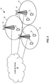
- Figure 1 illustrates a system in which there are two UEs in the system where one UE (UE1) is very close to the eNB and the other UE (UE2) is on the border of the cell.
- UE1 because it is very close to the eNB, the pathloss PL c is relatively small; and for UE2, the pathloss PL c is very large.
- P calculated is with higher probability to exceed the maximum transmitted power P CMAX,c ( i ).
- P CMAX,c ( i ) the maximum transmitted power
- a network node e.g. an eNB
- Such embodiments can potentially improve the UL control channel transmission efficiency for the Further Enhancement of CA (FeCA), reduce the impact of PUCCH quality on the Physical downlink Shared Channel (PDSCH) performance, and conserve UE power.
- FeCA Further Enhancement of CA
- PUCCH cannot be reliably detected. Without reliable PUCCH detection, many retransmissions may occur. In some worst cases, it will trigger many higher layer retransmissions, which will waste resources.
- a communication network 10 (which as an example is an LTE network) comprises a plurality of wireless communication devices 12 (e.g., conventional UEs, MTC / Machine-to-Machine (M2M) UEs) and a plurality of radio access nodes 14 (e.g., eNBs or other base stations).
- the communication network 10 is organized into cells 16, which are connected to a core network 18 via the corresponding radio access nodes 14.
- the radio access nodes 14 are capable of communicating with the wireless communication devices 12 and may also include any additional elements suitable to support communication between the wireless communication devices 12 or between a wireless communication device 12 and another communication device (such as a landline telephone).
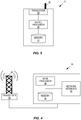
- wireless communication devices 12 may represent communication devices that include any suitable combination of hardware and/or software, these wireless communication devices 12 may, in certain embodiments, represent devices such as an example wireless communication device 12 illustrated in greater detail by Figure 3 .
- the illustrated radio access node 14 may represent network nodes that include any suitable combination of hardware and/or software, these nodes may, in particular embodiments, represent devices such as the example radio access node 14 illustrated in greater detail by Figure 4 .
- the wireless communication device 12 comprises a processor 20 (which may include, e.g., one or more Central Processing Units (CPUs), one or more Application Specific Integrated Circuits (ASICs), one or more Field Programmable Gate Arrays (FPGAs), or the like, or any combination thereof), memory 22, a transceiver 24, and an antenna 26.
- processor 20 which may include, e.g., one or more Central Processing Units (CPUs), one or more Application Specific Integrated Circuits (ASICs), one or more Field Programmable Gate Arrays (FPGAs), or the like, or any combination thereof
- memory 22 e.g., one or more Central Processing Units (CPUs), one or more Application Specific Integrated Circuits (ASICs), one or more Field Programmable Gate Arrays (FPGAs), or the like, or any combination thereof
- memory 22 e.g., one or more Central Processing Units (CPUs), one or more Application Specific Integrated Circuits (ASICs), one or more Field Programmable Gate Arrays (
- the radio access node 14 comprises a node processor 28 (which may include, e.g., one or more CPUs, one or more ASICs, one or more FPGAs, or the like, or any combination thereof), memory 30, a network interface 32, a transceiver 34, and an antenna 36.
- a node processor 28 which may include, e.g., one or more CPUs, one or more ASICs, one or more FPGAs, or the like, or any combination thereof
- memory 30 e.g., one or more CPUs, one or more ASICs, one or more FPGAs, or the like, or any combination thereof
- memory 30 e.g., one or more memory
- the radio access node 14 may comprise additional components to provide additional functionality, such as the functionality described herein and/or related supporting functionality.
- UCI Uplink Control Information
- PUSCH Physical uplink Shared Channel
- the described embodiments switch transmission methods for control channel information based on current operating conditions.
- the switching may be controlled by the radio access node 14 transmitting an indication to the wireless communication device 12 as illustrated in Figure 5 .
- the radio access node 14 is an eNB
- the wireless communication device 12 is a UE.
- the switching may be implemented in any of various alternative ways as described below with reference to the various disclosed embodiments.
- the eNB sends an indication to the UE to instruct the UE to switch, or change, the transmission method, or transmission scheme, utilized by the UE for PUCCH transmission (step 100).
- the UE switches, or changes, the transmission method, or transmission scheme, utilized by the UE for PUCCH transmission in accordance with the received indication (step 102).
- the radio access node 14 sends an indication to the wireless communication device 12 to instruct the wireless communication device 12 to switch the transmission methods for PUCCH.
- the radio access node 14 is an eNB
- the wireless communication device 12 is a UE; however, the eNB is only one example of a radio access node 14 and the UE is only one example of a wireless communication device 12.
- switching the transmission methods for PUCCH comprises the following features:
- the transmitter i.e., the eNB or more generally the radio access node 14
- the "reached SINR” is the actual SINR (i.e., the SINR actually achieved when targeting the desired SINR) at the eNB for signals received from the UE, which may be less than the desired, or target, SINR.
- the desired SINR cannot be achieved using power control, for instance, reached SINR - desired SINR ⁇ threshold 1
- the UE may be identified as a problem UE whose channel quality is not good enough.
- the eNB can send an indication to the UE to reduce its payload size for PUCCH. Otherwise, if the desired SINR can be well achieved or exceeded, for instance, reached SINR - desired SINR > threshold 2, the eNB can send an indication to the UE to use a larger payload size for PUCCH.
- the transmitter i.e., the eNB or more generally the radio access node 14 sends the indication based on a Power Headroom Report (PHR). If the PHR is smaller than the given threshold, the transmitter may send the indication to instruct the UE to use smaller payload size so that less power resources are used for PUCCH transmission. Otherwise, if the PHR is larger than another given threshold, the transmitter may send the indication to instruct the UE to use larger payload size and allocate more transmit power for PUCCH transmission.
- PHR Power Headroom Report
- the transmitter i.e., the eNB or more generally the radio access node 14
- the configuration comprises the number of CCs, the carrier type of each CC, and the allocation of each CC.
- there are two types of CCs one is a licensed carrier and one is an unlicensed carrier. If there are many unlicensed carriers, the requirement on the number of feedback bits may be not so tight and, thus, the payload of PUCCH may be expected to be reduced. In this case, the smaller payload size and less resource PUCCH may be used.
- the transmitter may indicate to the receiver (i.e., the UE or more generally the wireless communication device 12) that the receiver is to use the transmission methods with smaller payload size and/or less resources. Otherwise, the transmitter may indicate to the receiver that the receiver is to use transmission methods with large payload size and/or more resources.
- the indication is signaled by higher layer signaling. It may also be possible to signal the indication by Medium Access Control (MAC) Control Element (CE) or physical layer signaling (for instance, PDCCH order or one field in the DL scheduling DCI).
- MAC Medium Access Control
- CE Control Element
- physical layer signaling for instance, PDCCH order or one field in the DL scheduling DCI.
- the indication may be semi-statically (e.g., via higher layer signaling) configured, and/or the indication may be dynamically signaled (e.g., via MAC CE or physical layer signaling).
- the eNB sends the indicator, but the UE may miss the indicator. If the UE misses the indicator, this is not known by the eNB.
- the eNB may use an enhancement for PUCCH detection.
- One possible enhancement is to perform multiple blind detections based on all or partial hypothetic assumptions about the transmission methods for PUCCH. The eNB performs blind detection until the right information is obtained (i.e., until the PUCCH transmission from the UE is detected).
- the eNB does not send the indicator, and the UE makes a decision by itself on the transmission methods for PUCCH based on predefined rules.
- the eNB may perform blind detection on the transmission methods based on the predefined rules.
- different payloads may be used for the UE, and the eNB may try to use different hypothesis for the payload and decode the PUCCH until the right information is obtained.
- the PUCCH format indicator can be transmitted by the UE along with the PUCCH information. The eNB will first decode the PUCCH format indicator and then decode the corresponding PUCCH transmission.
- the method performed by the receiver which adjusts the PUCCH transmission according to the received indication from the eNB comprises the following features:
- the terminal i.e., the UE or more generally the wireless communication device 12
- power limitation based rules may be configured as follows:
- transmission-bits-based rules may be configured as follows.
- a plurality of intervals (of the number of bits) may be predefined, and a number of PRBs may be determined based on an interval in which the number of information bits falls.
- two intervals could be defined as [0 64] and [64 128], where one PRB is used if the number of information bits is less than 64 bits and two PRBs are used if the number of information bits is larger than 64 bits.
- the transmission methods for PUCCH may be switched.
- the UE indicates if the PUCCH transmission method is changed using one predefined field in UCI, e.g., this indicator can either be encoded together with the PUCCH transmission or separately.
- this indicator can either be encoded together with the PUCCH transmission or separately.
- the eNB determines how to interpret the received HARQ ACK bit according to said field.
- the UE supports both the third embodiment and the fourth embodiment at the same time. For example, if the UE receives the indication, the UE may have the behavior according to the third embodiment. Otherwise, if the UE does not receive the indication, UE may take action according to the fourth embodiment.
- FIG. 6 illustrates the operation of the wireless communication device (WD) 12 and the radio access node 14 (which for this example is a base station (BS) 14) according to some of the embodiments described above.
- the base station 14 triggers a change, or switching, of the transmission method, or scheme, utilized by the wireless communication device 12 (step 200).
- this trigger may be in response to current operating conditions such as, e.g., the gap between the achieved SINR and the desired SINR, a PHR from the wireless communication device 12, the CC configuration for the wireless communication device 12, or the like, or any combination thereof.
- the base station 14 (e.g., in response to the trigger of step 200) sends an indicator, or indication, to the wireless communication device 12 that indicates that the wireless communication device 12 is to switch, or change, the transmission method, or scheme, utilized by the wireless communication device 12 for PUCCH transmission (step 202).
- the indicator may be or include a bundling indicator (i.e., an indication that the wireless communication device 12 is to switch the PUCCH transmission scheme to use some type(s) of bundling for, e.g., HARQ-ACK feedback).
- the indicator may indicate that spatial domain bundling is to be used (i.e., spatial domain bundling of, e.g., HARQ-ACKs).
- time domain and/or frequency domain bundling may additionally or alternatively be indicated.
- the indicator may additionally or alternatively indicate that there is to be a change in resources used by the wireless communication device 12 for PUCCH transmission.
- the indicator may indicate that the PUCCH transmission scheme is to be changed to use a greater number of time-frequency resources (e.g., PRBs) or a lesser number of time-frequency resources (e.g., PRBs).
- the indicator may indicate the number of time-frequency resources (e.g., PRBs) to be utilized for PUCCH transmission.
- the indicator may additionally or alternatively indicate a change in a MCS utilized for PUCCH transmission.
- the wireless communication device 12 Upon receiving the indication, the wireless communication device 12 changes, or switches, the transmission method, or scheme, utilized by the wireless communication device 12 for PUCCH transmission in accordance with the indicator (step 204). For example, if the indicator is an indication that bundling (e.g., spatial domain bundling) is to be used, then the wireless communication device 12 changes the PUCCH transmission scheme to use bundling as indicated by the indicator. As another example, if the indicator is an indication of the number of time-frequency resources (e.g., PRBs) to be used for PUCCH transmission, then the wireless communication device 12 changes the PUCCH transmission scheme to use the indicated number of time-frequency resources. The wireless communication device 12 then transmits a PUCCH transmission to the base station 14 in accordance with the changed, or switched, PUCCH transmission scheme (step 206).
- bundling e.g., spatial domain bundling
- the wireless communication device 12 changes the PUCCH transmission scheme to use bundling as indicated by the indicator.
- the base station 14 operates to detect the PUCCH transmission from the wireless communication device 12 (step 208).
- the base station 14 may utilize an enhanced PUCCH detection scheme (e.g., blind decoding for multiple hypotheses in the event that the wireless communication device 12 may not have received the indicator).
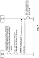
- Figure 7 illustrates the operation of the wireless communication device (WD) 12 and the radio access node 14 (which for this example is a base station (BS) 14) according to some other embodiments described above.
- the wireless communication device 12 makes a decision on its own as to whether to change, or switch, the PUCCH transmission method, or scheme, utilized by the wireless communication device 12, as described above.
- the wireless communication device 12 makes a decision to change, or switch, the PUCCH transmission method, or scheme, utilized by the wireless communication device 12, e.g., based on one or more predefined rules, as described above (step 300).
- the wireless communication device 12 changes the PUCCH transmission scheme (step 302).
- the wireless communication device 12 changes the PUCCH transmission scheme to use bundling (e.g., spatial domain bundling, frequency domain bundling, and/or time domain bundling), change the resources used for PUCCH transmission (e.g., change the number of time-frequency resources used), and/or change the MCS used for the PUCCH transmission scheme.
- the wireless communication device 12 then optionally (i.e., in some embodiments) transmits an indicator of the changed PUCCH transmission scheme (e.g., in UCI) and transmits a PUCCH transmission to the base station 14 in accordance with the changed, or switched, PUCCH transmission scheme (steps 304 and 306). While illustrated separately, in some embodiments, the indicator is included in the PUCCH transmission such that the base station 14 will first decode the indicator and then decode the rest of the PUCCH transmission in accordance with the indicator.
- bundling e.g., spatial domain bundling, frequency domain bundling, and/or time domain bundling
- the base station 14 operates to detect the PUCCH transmission from the wireless communication device 12 (step 308).
- the base station 14 may utilize an enhanced PUCCH detection scheme (e.g., blind decoding for multiple hypotheses in the event that the wireless communication device 12 may not have received the indicator), as described above.
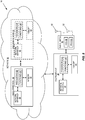
- Figure 8 is a schematic block diagram that illustrates a virtualized embodiment of the base station 14 (or more generally the radio access node 14) according to some embodiments of the present disclosure. This discussion is equally applicable to other types of radio access nodes. Further, other types of network nodes may have similar architectures (particularly with respect to including processor(s), memory, and a network interface).
- a "virtualized" radio access node is a radio access node in which at least a portion of the signal processing (e.g., baseband signal processing and/or signal processing) of the radio access node is implemented as a virtual component (e.g., via a virtual machine(s) executing on a physical processing node(s) in a network(s)).
- the base station 14 includes a baseband unit 38 that includes the one or more processors 40 (e.g., CPUs, ASICs, FPGAs, and/or the like), memory 42, and a network interface 44 as well as the one or more radio units 46 that each includes one or more transmitters 48 and one or more receivers 50 coupled to one or more antennas 52.
- the components of the baseband unit 38 correspond to the respective components (i.e., the processor 28, the memory 30, and network interface 32) of the base station 14 of Figure 4
- the radio unit(s) 46 correspond to the transceiver 34 of Figure 4
- the baseband unit 38 is connected to the radio unit(s) 46 via, for example, an optical cable or the like.
- the baseband unit 38 is connected to one or more processing nodes 58 coupled to or included as part of a network(s) 56 via the network interface 44.
- Each processing node 58 includes one or more processors 60 (e.g., CPUs, ASICs, FPGAs, and/or the like), memory 62, and a network interface 64.
- functions 54 of the base station 14 described herein are implemented at the one or more processing nodes 58 or distributed across the baseband unit 38 and the one or more processing nodes 58 in any desired manner.
- some or all of the functions 54 of the base station 14 described herein are implemented as virtual components executed by one or more virtual machines implemented in a virtual environment(s) hosted by the processing node(s) 58.
- additional signaling or communication between the processing node(s) 58 and the baseband unit 38 in order to carry out at least some of the desired functions is provided.
- the baseband unit 38 may not be included, in which case the radio unit(s) 46 communicate directly with the processing node(s) 58 via an appropriate network interface(s).
- a computer program including instructions which, when executed by at least one processor, causes the at least one processor to carry out the functionality of the base station 14 (or more generally a radio access node) or a node (e.g., a processing node 58 implementing one or more of the functions 54 of the radio access node in a virtual environment) according to any of the embodiments described herein is provided.
- a carrier containing the aforementioned computer program product is provided.
- the carrier is one of an electronic signal, an optical signal, a radio signal, or a computer readable storage medium (e.g., a non-transitory computer readable medium such as memory).
- FIG. 9 illustrates the base station 14 according to some other embodiments of the present disclosure.
- the base station 14 (or more generally the radio access node 14) includes one or more modules 66, each of which is implemented in software.
- the one or more modules 66 include an indicator transmission module that operates to transmit an indicator to the wireless communication device 12, as described above.
- the one or more modules 66 also include a PUCCH detection module that operates to detect a PUCCH transmission from the wireless communication device 12, as described above.
- the wireless communication device 12 includes one or more modules 68, each of which is implemented in software.
- the one or more modules 68 include an indicator reception module that operates to receive an indicator from the base station 14, as described above.
- the one or more modules 68 include a decision module that operates to make a decision as to whether to change, or switch, the PUCCH transmission scheme, as described above.
- the one or more modules 68 also include a switching module that operates to change, or switch, the PUCCH transmission scheme in accordance with either the indicator received from the base station 14 or the decision made by the wireless communication device 12, depending on the particular embodiment.
- the one or more modules 68 also include a PUCCH transmission module that operates to transmit (via an associated transceiver, which is not shown) a PUCCH transmission using the changed PUCCH transmission scheme, as described above.
Landscapes
- Engineering & Computer Science (AREA)
- Signal Processing (AREA)
- Computer Networks & Wireless Communication (AREA)
- Quality & Reliability (AREA)
- Mobile Radio Communication Systems (AREA)
Claims (15)
- Procédé de fonctionnement d'un nœud d'accès radio (14) dans un réseau de communication cellulaire (10), comprenant :en réponse à un déclenchement sur la base de conditions de fonctionnement actuelles, la transmission (202) d'un indicateur de regroupement à destination d'un dispositif sans fil (12) qui indique qu'un schéma de transmission utilisé par le dispositif sans fil (12) pour une transmission d'un canal de commande de liaison montante doit être changé,dans lequel l'indicateur de regroupement indique que le schéma de transmission doit utiliser un schéma de regroupement comprenant un regroupement dans le domaine spatial,dans lequel le déclenchement est un ou plusieurs d'un groupe se composant de : un écart entre un rapport de signal sur interférence plus bruit, SINR, obtenu pour une transmission de liaison montante depuis le dispositif sans fil (12) au nœud d'accès radio (14) et un SINR souhaité ; un rapport de marge de puissance, PHR, reçu en provenance du dispositif sans fil (12) ; et une configuration de porteuse composante pour le dispositif sans fil (12).
- Procédé selon la revendication 1, comprenant en outre la détection (208) d'une transmission du canal de commande de liaison montante depuis le dispositif sans fil (12).
- Procédé selon la revendication 2, dans lequel la détection (208) de la transmission du canal de commande de liaison montante depuis le dispositif sans fil (12) comprend une tentative de décodage à l'aveugle de la transmission du canal de commande de liaison montante en utilisant de multiples hypothèses relatives à un schéma de transmission utilisé par le dispositif sans fil (12) pour le canal de commande de liaison montante.
- Procédé selon la revendication 1, 2 ou 3, dans lequel le schéma de regroupement comprend en outre au moins l'un d'un regroupement dans le domaine de fréquence et d'un regroupement dans le domaine de temps.
- Procédé selon l'une quelconque des revendications 1 à 4, dans lequel l'indicateur de regroupement engendre un changement d'un nombre de ressources utilisées par le schéma de transmission utilisé par le dispositif sans fil (12) pour une transmission du canal de commande de liaison montante.
- Procédé selon l'une quelconque des revendications 1 à 4, dans lequel l'indicateur de regroupement indique qu'un nombre de ressources de temps-fréquence utilisées pour le schéma de transmission utilisé par le dispositif sans fil (12) pour une transmission du canal de commande de liaison montante doit être changé.
- Nœud d'accès radio (14) pour un réseau de communication cellulaire (10), comprenant :un émetteur-récepteur (34) ;un processeur (28) ; etune mémoire (30) stockant des instructions exécutables par le processeur (28) de telle manière que le nœud d'accès radio (14) soit utilisable pour :en réponse à un déclenchement sur la base de conditions de fonctionnement actuelles, transmettre, par l'intermédiaire de l'émetteur-récepteur (34), un indicateur de regroupement à destination d'un dispositif sans fil (12) qui indique qu'un schéma de transmission utilisé par le dispositif sans fil (12) pour une transmission d'un canal de commande de liaison montante doit être changé,dans lequel l'indicateur de regroupement indique que le schéma de transmission doit utiliser un schéma de regroupement comprenant un regroupement dans le domaine spatial,dans lequel le déclenchement est un ou plusieurs d'un groupe se composant de : un écart entre un rapport de signal sur interférence plus bruit, SINR, obtenu pour une transmission de liaison montante depuis le dispositif sans fil (12) au nœud d'accès radio (14) et un SINR souhaité ; un rapport de marge de puissance, PHR, reçu en provenance du dispositif sans fil (12) ; et une configuration de porteuse composante pour le dispositif sans fil (12).
- Nœud d'accès radio (14) selon la revendication 7, dans lequel le schéma de regroupement comprend en outre au moins l'un d'un regroupement dans le domaine de fréquence et d'un regroupement dans le domaine de temps.
- Nœud d'accès radio (14) selon la revendication 7, dans lequel l'indicateur de regroupement engendre un changement d'un nombre de ressources utilisées par le schéma de transmission utilisé par le dispositif sans fil (12) pour une transmission du canal de commande de liaison montante.
- Nœud d'accès radio (14) selon la revendication 7, dans lequel l'indicateur de regroupement indique qu'un nombre de ressources de temps-fréquence utilisées pour le schéma de transmission utilisé par le dispositif sans fil (12) pour une transmission du canal de commande de liaison montante doit être changé.
- Nœud d'accès radio (14) selon la revendication 7, comprenant en outre
des moyens pour la détection d'une transmission du canal de commande de liaison montante depuis le dispositif sans fil (12). - Programme informatique comprenant des instructions qui, lorsqu'elles sont exécutées sur au moins un processeur, amènent l'au moins un processeur à effectuer le procédé selon l'une quelconque des revendications 1 à 6.
- Procédé de fonctionnement d'un dispositif sans fil (12) dans un réseau de communication cellulaire (10), comprenant :la réception (202) d'un indicateur de regroupement transmis depuis une station de base (14) en réponse à un déclenchement sur la base de conditions de fonctionnement actuelles, l'indicateur de regroupement indiquant qu'un schéma de transmission utilisé par le dispositif sans fil (12) pour une transmission d'un canal de commande de liaison montante doit être changé ; età la réception de l'indicateur de regroupement, le changement (204) du schéma de transmission utilisé par le dispositif sans fil (12) pour une transmission du canal de commande de liaison montante en fonction de l'indicateur de regroupement, dans lequel l'indicateur de regroupement indique que le schéma de transmission doit utiliser un schéma de regroupement comprenant un regroupement dans le domaine spatial,dans lequel le déclenchement est un ou plusieurs d'un groupe se composant de : un écart entre un rapport de signal sur interférence plus bruit, SINR, obtenu pour une transmission de liaison montante depuis le dispositif sans fil (12) au nœud d'accès radio (14) et un SINR souhaité ; un rapport de marge de puissance, PHR, reçu en provenance du dispositif sans fil (12) ; et une configuration de porteuse composante pour le dispositif sans fil (12).
- Dispositif sans fil (12) activé pour fonctionner dans un réseau de communication cellulaire (10), comprenant :un émetteur-récepteur (24) ;un processeur (20) ; etune mémoire (22) stockant des instructions exécutables par le processeur (20) de telle manière que le dispositif sans fil (12) soit utilisable pour :recevoir, par l'intermédiaire de l'émetteur-récepteur (24), un indicateur de regroupement transmis depuis une station de base (14) en réponse à un déclenchement sur la base de conditions de fonctionnement actuelles, l'indicateur de regroupement indiquant qu'un schéma de transmission utilisé par le dispositif sans fil (12) pour une transmission d'un canal de commande de liaison montante doit être changé ; età la réception de l'indicateur, changer le schéma de transmission utilisé par le dispositif sans fil (12) pour une transmission du canal de commande de liaison montante en fonction de l'indicateur de regroupement, dans lequel l'indicateur de regroupement indique que le schéma de transmission doit utiliser un schéma de regroupement comprenant un regroupement dans le domaine spatial,dans lequel le déclenchement est un ou plusieurs d'un groupe se composant de : un écart entre un rapport de signal sur interférence plus bruit, SINR, obtenu pour une transmission de liaison montante depuis le dispositif sans fil (12) au nœud d'accès radio (14) et un SINR souhaité ; un rapport de marge de puissance, PHR, reçu en provenance du dispositif sans fil (12) ; et une configuration de porteuse composante pour le dispositif sans fil (12).
- Programme informatique comprenant des instructions qui, lorsqu'elles sont exécutées sur au moins un processeur, amènent l'au moins un processeur à effectuer le procédé selon la revendication 13.
Applications Claiming Priority (3)
| Application Number | Priority Date | Filing Date | Title |
|---|---|---|---|
| PCT/CN2015/076162 WO2016161597A1 (fr) | 2015-04-09 | 2015-04-09 | Procédés de transmission adaptative d'informations de commande de liaison montante |
| CN2015087000 | 2015-08-14 | ||
| PCT/IB2016/051950 WO2016162803A1 (fr) | 2015-04-09 | 2016-04-06 | Procédés de transmission adaptative pour des informations de commande de liaison montante |
Publications (2)
| Publication Number | Publication Date |
|---|---|
| EP3281339A1 EP3281339A1 (fr) | 2018-02-14 |
| EP3281339B1 true EP3281339B1 (fr) | 2020-06-03 |
Family
ID=55702045
Family Applications (1)
| Application Number | Title | Priority Date | Filing Date |
|---|---|---|---|
| EP16715634.8A Active EP3281339B1 (fr) | 2015-04-09 | 2016-04-06 | Procédés de transmission adaptative pour des informations de commande de liaison montante |
Country Status (5)
| Country | Link |
|---|---|
| US (1) | US20180097578A1 (fr) |
| EP (1) | EP3281339B1 (fr) |
| CN (1) | CN107683576B (fr) |
| BR (1) | BR112017021599A2 (fr) |
| WO (1) | WO2016162803A1 (fr) |
Families Citing this family (19)
| Publication number | Priority date | Publication date | Assignee | Title |
|---|---|---|---|---|
| EP3989466B1 (fr) * | 2015-09-17 | 2024-03-20 | Apple Inc. | Transmission d'informations de commande de liaison montante dans des systèmes sans fil |
| US11363572B2 (en) * | 2016-08-01 | 2022-06-14 | Qualcomm Incorporated | Uplink channel dynamic waveform switching |
| JP6763229B2 (ja) * | 2016-08-08 | 2020-09-30 | ソニー株式会社 | 通信装置、通信方法、及びプログラム |
| CN107889247B (zh) * | 2016-09-30 | 2022-12-30 | 中兴通讯股份有限公司 | 上行控制信息传输/配置指示方法、装置、终端及基站 |
| EP3535919A4 (fr) * | 2016-11-04 | 2020-06-24 | Telefonaktiebolaget LM Ericsson (publ) | Stratégies de transmission d'ack/nack |
| CN109891793B (zh) | 2016-11-04 | 2022-04-12 | 瑞典爱立信有限公司 | 无线电节点和操作节点的方法 |
| EP3588884B1 (fr) * | 2017-02-21 | 2022-08-03 | LG Electronics Inc. | Procédé de transmission de srs dans un système de communication sans fil, et terminal associé |
| WO2018205257A1 (fr) | 2017-05-12 | 2018-11-15 | Qualcomm Incorporated | Conception de nr phr pour un déploiement d'ondes millimétriques |
| WO2018232734A1 (fr) | 2017-06-23 | 2018-12-27 | Qualcomm Incorporated | Signalisation de stratégie de transmission |
| CN109391355B (zh) * | 2017-08-11 | 2020-10-23 | 华为技术有限公司 | 无线通信的方法、芯片和系统 |
| JP7320841B2 (ja) * | 2017-11-17 | 2023-08-04 | 株式会社Nttドコモ | 端末、無線通信方法、基地局及びシステム |
| CN111543082B (zh) | 2018-02-11 | 2022-12-20 | 富士通株式会社 | 小区配置装置及方法 |
| CN110149703B (zh) | 2018-02-12 | 2021-04-27 | 北京紫光展锐通信技术有限公司 | 上行控制信息的发送方法及装置、存储介质、用户设备 |
| FR3081279A1 (fr) * | 2018-05-18 | 2019-11-22 | Orange | Procede centralise d'allocation de ressources de transmission a des terminaux d2d dans un reseau d'acces cellulaire. |
| US11382048B2 (en) | 2018-05-22 | 2022-07-05 | Qualcomm Incorporated | Multiplexing solutions in dual connectivity |
| CN118473619A (zh) * | 2018-09-28 | 2024-08-09 | 索尼集团公司 | 发现信令的方法、相关网络节点和相关无线电子设备 |
| CN111586826B (zh) * | 2019-02-15 | 2023-06-16 | 上海朗帛通信技术有限公司 | 一种被用于无线通信的节点中的方法和装置 |
| US12256379B2 (en) * | 2020-10-16 | 2025-03-18 | Qualcomm Incorporated | Dynamic change of mapping payload size to PUCCH configuration |
| US12425983B2 (en) * | 2021-12-03 | 2025-09-23 | Qualcomm Incorporated | Power headroom reporting for dynamic power aggregation |
Family Cites Families (12)
| Publication number | Priority date | Publication date | Assignee | Title |
|---|---|---|---|---|
| US9402247B2 (en) * | 2008-10-20 | 2016-07-26 | Interdigital Patent Holdings, Inc. | Uplink control information transmission methods for carrier aggregation |
| WO2011041623A1 (fr) * | 2009-10-01 | 2011-04-07 | Interdigital Patent Holdings, Inc. | Transmission de données de commande en liaison montante |
| US9819458B2 (en) * | 2010-08-13 | 2017-11-14 | Qualcomm Incorporation | Feedback bundling for power-limited devices in wireless communications |
| US8582518B2 (en) * | 2010-11-09 | 2013-11-12 | Telefonaktiebolaget L M Ericsson (Publ) | Power control for ACK/NACK formats with carrier aggregation |
| CN103503360A (zh) * | 2011-04-29 | 2014-01-08 | 交互数字专利控股公司 | 具有子帧限制的载波的载波聚合 |
| WO2012169753A2 (fr) * | 2011-06-06 | 2012-12-13 | 엘지전자 주식회사 | Procédé de transmission de données de contrôle sur la liaison montante et équipement d'utilisateur, et procédé de réception de données de contrôle sur la liaison montante et station de base |
| CN103368709B (zh) * | 2012-04-09 | 2018-08-14 | 中兴通讯股份有限公司 | 一种混合自动重传请求确认应答信息发送方法及装置 |
| EP2847908A4 (fr) * | 2012-05-11 | 2015-12-30 | Nokia Solutions & Networks Oy | Groupage de bits ack/nak dans des scénarios d'agrégation de porteuses |
| US9655088B2 (en) * | 2013-04-17 | 2017-05-16 | Qualcomm Incorporated | Utilizing unused uplink sequence shifts for signaling |
| CN111092698B (zh) * | 2013-09-27 | 2021-12-17 | 华为技术有限公司 | 无线通信系统中的方法和节点 |
| US9949275B2 (en) * | 2013-10-01 | 2018-04-17 | Qualcomm Incorporated | Physical uplink control management in LTE/LTE-A systems with unlicensed spectrum |
| CN113115454A (zh) * | 2015-04-08 | 2021-07-13 | 华为技术有限公司 | 网络节点、用户设备及其方法 |
-
2016
- 2016-04-06 BR BR112017021599A patent/BR112017021599A2/pt not_active IP Right Cessation
- 2016-04-06 WO PCT/IB2016/051950 patent/WO2016162803A1/fr not_active Ceased
- 2016-04-06 CN CN201680034036.9A patent/CN107683576B/zh active Active
- 2016-04-06 EP EP16715634.8A patent/EP3281339B1/fr active Active
- 2016-05-06 US US15/564,591 patent/US20180097578A1/en not_active Abandoned
Non-Patent Citations (1)
| Title |
|---|
| None * |
Also Published As
| Publication number | Publication date |
|---|---|
| US20180097578A1 (en) | 2018-04-05 |
| BR112017021599A2 (pt) | 2018-07-03 |
| EP3281339A1 (fr) | 2018-02-14 |
| CN107683576A (zh) | 2018-02-09 |
| WO2016162803A1 (fr) | 2016-10-13 |
| HK1250853A1 (zh) | 2019-01-11 |
| CN107683576B (zh) | 2021-09-17 |
Similar Documents
| Publication | Publication Date | Title |
|---|---|---|
| EP3281339B1 (fr) | Procédés de transmission adaptative pour des informations de commande de liaison montante | |
| US10848293B2 (en) | Method for transmitting ACK/NACK in wireless communication system and device using same | |
| US20220408416A1 (en) | Method and apparatus for subband based channel access in wireless communication system | |
| US10587387B2 (en) | Method and apparatus for transmitting uplink control information (UCI) in wireless communication system | |
| US10615939B2 (en) | Method and device for transmitting ACK/NACK in wireless communication system | |
| KR102818510B1 (ko) | 무선 통신 시스템에서 제어 정보 송수신 방법 및 장치 | |
| KR102584701B1 (ko) | 무선 통신 시스템에서 비면허대역의 채널 접속 방법 및 장치 | |
| JP7145899B2 (ja) | 1セグメントpucchフォーマット | |
| EP3286863B1 (fr) | Adaptation de liaison pdcch améliorée dans une agrégation de porteuses | |
| KR102208133B1 (ko) | 송신 타입 및 ue 처리 능력에 따른 송신 지연 | |
| EP3440888B1 (fr) | Noeud de réseau radio, dispositif sans fil et procédés réalisés dans ces derniers | |
| EP4608040A2 (fr) | Gestion dynamique de ressources de signalisation de commande de liaison montante dans un réseau sans fil | |
| EP3553986B1 (fr) | Procédé de transmission, équipement de réseau et équipement terminal | |
| KR102830394B1 (ko) | 무선 통신 시스템에서 통신을 수행하는 방법 및 장치 | |
| US20220104265A1 (en) | Method and apparatus for performing random access in wireless communication system | |
| US10491337B2 (en) | Method for transmitting ACK/NACK in wireless communication system and apparatus using same | |
| US10880053B2 (en) | Wireless device, a network node and methods therein for handling transmissions in a wireless communications network | |
| WO2016161597A1 (fr) | Procédés de transmission adaptative d'informations de commande de liaison montante | |
| HK1250853B (zh) | 对於上行链路控制信息的自适应传送方法 |
Legal Events
| Date | Code | Title | Description |
|---|---|---|---|
| STAA | Information on the status of an ep patent application or granted ep patent |
Free format text: STATUS: THE INTERNATIONAL PUBLICATION HAS BEEN MADE |
|
| PUAI | Public reference made under article 153(3) epc to a published international application that has entered the european phase |
Free format text: ORIGINAL CODE: 0009012 |
|
| STAA | Information on the status of an ep patent application or granted ep patent |
Free format text: STATUS: REQUEST FOR EXAMINATION WAS MADE |
|
| 17P | Request for examination filed |
Effective date: 20171024 |
|
| AK | Designated contracting states |
Kind code of ref document: A1 Designated state(s): AL AT BE BG CH CY CZ DE DK EE ES FI FR GB GR HR HU IE IS IT LI LT LU LV MC MK MT NL NO PL PT RO RS SE SI SK SM TR |
|
| AX | Request for extension of the european patent |
Extension state: BA ME |
|
| DAV | Request for validation of the european patent (deleted) | ||
| DAX | Request for extension of the european patent (deleted) | ||
| STAA | Information on the status of an ep patent application or granted ep patent |
Free format text: STATUS: EXAMINATION IS IN PROGRESS |
|
| 17Q | First examination report despatched |
Effective date: 20191106 |
|
| GRAP | Despatch of communication of intention to grant a patent |
Free format text: ORIGINAL CODE: EPIDOSNIGR1 |
|
| STAA | Information on the status of an ep patent application or granted ep patent |
Free format text: STATUS: GRANT OF PATENT IS INTENDED |
|
| INTG | Intention to grant announced |
Effective date: 20200204 |
|
| GRAS | Grant fee paid |
Free format text: ORIGINAL CODE: EPIDOSNIGR3 |
|
| GRAA | (expected) grant |
Free format text: ORIGINAL CODE: 0009210 |
|
| STAA | Information on the status of an ep patent application or granted ep patent |
Free format text: STATUS: THE PATENT HAS BEEN GRANTED |
|
| AK | Designated contracting states |
Kind code of ref document: B1 Designated state(s): AL AT BE BG CH CY CZ DE DK EE ES FI FR GB GR HR HU IE IS IT LI LT LU LV MC MK MT NL NO PL PT RO RS SE SI SK SM TR |
|
| REG | Reference to a national code |
Ref country code: GB Ref legal event code: FG4D |
|
| REG | Reference to a national code |
Ref country code: CH Ref legal event code: EP Ref country code: AT Ref legal event code: REF Ref document number: 1278169 Country of ref document: AT Kind code of ref document: T Effective date: 20200615 |
|
| REG | Reference to a national code |
Ref country code: DE Ref legal event code: R096 Ref document number: 602016037445 Country of ref document: DE |
|
| REG | Reference to a national code |
Ref country code: LT Ref legal event code: MG4D |
|
| PG25 | Lapsed in a contracting state [announced via postgrant information from national office to epo] |
Ref country code: NO Free format text: LAPSE BECAUSE OF FAILURE TO SUBMIT A TRANSLATION OF THE DESCRIPTION OR TO PAY THE FEE WITHIN THE PRESCRIBED TIME-LIMIT Effective date: 20200903 Ref country code: GR Free format text: LAPSE BECAUSE OF FAILURE TO SUBMIT A TRANSLATION OF THE DESCRIPTION OR TO PAY THE FEE WITHIN THE PRESCRIBED TIME-LIMIT Effective date: 20200904 Ref country code: SE Free format text: LAPSE BECAUSE OF FAILURE TO SUBMIT A TRANSLATION OF THE DESCRIPTION OR TO PAY THE FEE WITHIN THE PRESCRIBED TIME-LIMIT Effective date: 20200603 Ref country code: FI Free format text: LAPSE BECAUSE OF FAILURE TO SUBMIT A TRANSLATION OF THE DESCRIPTION OR TO PAY THE FEE WITHIN THE PRESCRIBED TIME-LIMIT Effective date: 20200603 Ref country code: LT Free format text: LAPSE BECAUSE OF FAILURE TO SUBMIT A TRANSLATION OF THE DESCRIPTION OR TO PAY THE FEE WITHIN THE PRESCRIBED TIME-LIMIT Effective date: 20200603 |
|
| REG | Reference to a national code |
Ref country code: NL Ref legal event code: MP Effective date: 20200603 |
|
| PG25 | Lapsed in a contracting state [announced via postgrant information from national office to epo] |
Ref country code: HR Free format text: LAPSE BECAUSE OF FAILURE TO SUBMIT A TRANSLATION OF THE DESCRIPTION OR TO PAY THE FEE WITHIN THE PRESCRIBED TIME-LIMIT Effective date: 20200603 Ref country code: BG Free format text: LAPSE BECAUSE OF FAILURE TO SUBMIT A TRANSLATION OF THE DESCRIPTION OR TO PAY THE FEE WITHIN THE PRESCRIBED TIME-LIMIT Effective date: 20200903 Ref country code: LV Free format text: LAPSE BECAUSE OF FAILURE TO SUBMIT A TRANSLATION OF THE DESCRIPTION OR TO PAY THE FEE WITHIN THE PRESCRIBED TIME-LIMIT Effective date: 20200603 Ref country code: RS Free format text: LAPSE BECAUSE OF FAILURE TO SUBMIT A TRANSLATION OF THE DESCRIPTION OR TO PAY THE FEE WITHIN THE PRESCRIBED TIME-LIMIT Effective date: 20200603 |
|
| REG | Reference to a national code |
Ref country code: AT Ref legal event code: MK05 Ref document number: 1278169 Country of ref document: AT Kind code of ref document: T Effective date: 20200603 |
|
| PG25 | Lapsed in a contracting state [announced via postgrant information from national office to epo] |
Ref country code: NL Free format text: LAPSE BECAUSE OF FAILURE TO SUBMIT A TRANSLATION OF THE DESCRIPTION OR TO PAY THE FEE WITHIN THE PRESCRIBED TIME-LIMIT Effective date: 20200603 Ref country code: AL Free format text: LAPSE BECAUSE OF FAILURE TO SUBMIT A TRANSLATION OF THE DESCRIPTION OR TO PAY THE FEE WITHIN THE PRESCRIBED TIME-LIMIT Effective date: 20200603 |
|
| PG25 | Lapsed in a contracting state [announced via postgrant information from national office to epo] |
Ref country code: AT Free format text: LAPSE BECAUSE OF FAILURE TO SUBMIT A TRANSLATION OF THE DESCRIPTION OR TO PAY THE FEE WITHIN THE PRESCRIBED TIME-LIMIT Effective date: 20200603 Ref country code: PT Free format text: LAPSE BECAUSE OF FAILURE TO SUBMIT A TRANSLATION OF THE DESCRIPTION OR TO PAY THE FEE WITHIN THE PRESCRIBED TIME-LIMIT Effective date: 20201006 Ref country code: IT Free format text: LAPSE BECAUSE OF FAILURE TO SUBMIT A TRANSLATION OF THE DESCRIPTION OR TO PAY THE FEE WITHIN THE PRESCRIBED TIME-LIMIT Effective date: 20200603 Ref country code: SM Free format text: LAPSE BECAUSE OF FAILURE TO SUBMIT A TRANSLATION OF THE DESCRIPTION OR TO PAY THE FEE WITHIN THE PRESCRIBED TIME-LIMIT Effective date: 20200603 Ref country code: EE Free format text: LAPSE BECAUSE OF FAILURE TO SUBMIT A TRANSLATION OF THE DESCRIPTION OR TO PAY THE FEE WITHIN THE PRESCRIBED TIME-LIMIT Effective date: 20200603 Ref country code: RO Free format text: LAPSE BECAUSE OF FAILURE TO SUBMIT A TRANSLATION OF THE DESCRIPTION OR TO PAY THE FEE WITHIN THE PRESCRIBED TIME-LIMIT Effective date: 20200603 Ref country code: CZ Free format text: LAPSE BECAUSE OF FAILURE TO SUBMIT A TRANSLATION OF THE DESCRIPTION OR TO PAY THE FEE WITHIN THE PRESCRIBED TIME-LIMIT Effective date: 20200603 Ref country code: ES Free format text: LAPSE BECAUSE OF FAILURE TO SUBMIT A TRANSLATION OF THE DESCRIPTION OR TO PAY THE FEE WITHIN THE PRESCRIBED TIME-LIMIT Effective date: 20200603 |
|
| PG25 | Lapsed in a contracting state [announced via postgrant information from national office to epo] |
Ref country code: SK Free format text: LAPSE BECAUSE OF FAILURE TO SUBMIT A TRANSLATION OF THE DESCRIPTION OR TO PAY THE FEE WITHIN THE PRESCRIBED TIME-LIMIT Effective date: 20200603 Ref country code: PL Free format text: LAPSE BECAUSE OF FAILURE TO SUBMIT A TRANSLATION OF THE DESCRIPTION OR TO PAY THE FEE WITHIN THE PRESCRIBED TIME-LIMIT Effective date: 20200603 Ref country code: IS Free format text: LAPSE BECAUSE OF FAILURE TO SUBMIT A TRANSLATION OF THE DESCRIPTION OR TO PAY THE FEE WITHIN THE PRESCRIBED TIME-LIMIT Effective date: 20201003 |
|
| REG | Reference to a national code |
Ref country code: DE Ref legal event code: R097 Ref document number: 602016037445 Country of ref document: DE |
|
| PLBE | No opposition filed within time limit |
Free format text: ORIGINAL CODE: 0009261 |
|
| STAA | Information on the status of an ep patent application or granted ep patent |
Free format text: STATUS: NO OPPOSITION FILED WITHIN TIME LIMIT |
|
| PG25 | Lapsed in a contracting state [announced via postgrant information from national office to epo] |
Ref country code: DK Free format text: LAPSE BECAUSE OF FAILURE TO SUBMIT A TRANSLATION OF THE DESCRIPTION OR TO PAY THE FEE WITHIN THE PRESCRIBED TIME-LIMIT Effective date: 20200603 |
|
| 26N | No opposition filed |
Effective date: 20210304 |
|
| PG25 | Lapsed in a contracting state [announced via postgrant information from national office to epo] |
Ref country code: SI Free format text: LAPSE BECAUSE OF FAILURE TO SUBMIT A TRANSLATION OF THE DESCRIPTION OR TO PAY THE FEE WITHIN THE PRESCRIBED TIME-LIMIT Effective date: 20200603 |
|
| PG25 | Lapsed in a contracting state [announced via postgrant information from national office to epo] |
Ref country code: MC Free format text: LAPSE BECAUSE OF FAILURE TO SUBMIT A TRANSLATION OF THE DESCRIPTION OR TO PAY THE FEE WITHIN THE PRESCRIBED TIME-LIMIT Effective date: 20200603 |
|
| PG25 | Lapsed in a contracting state [announced via postgrant information from national office to epo] |
Ref country code: LU Free format text: LAPSE BECAUSE OF NON-PAYMENT OF DUE FEES Effective date: 20210406 |
|
| REG | Reference to a national code |
Ref country code: BE Ref legal event code: MM Effective date: 20210430 |
|
| PG25 | Lapsed in a contracting state [announced via postgrant information from national office to epo] |
Ref country code: LI Free format text: LAPSE BECAUSE OF NON-PAYMENT OF DUE FEES Effective date: 20210430 Ref country code: CH Free format text: LAPSE BECAUSE OF NON-PAYMENT OF DUE FEES Effective date: 20210430 |
|
| PG25 | Lapsed in a contracting state [announced via postgrant information from national office to epo] |
Ref country code: IE Free format text: LAPSE BECAUSE OF NON-PAYMENT OF DUE FEES Effective date: 20210406 |
|
| PG25 | Lapsed in a contracting state [announced via postgrant information from national office to epo] |
Ref country code: IS Free format text: LAPSE BECAUSE OF FAILURE TO SUBMIT A TRANSLATION OF THE DESCRIPTION OR TO PAY THE FEE WITHIN THE PRESCRIBED TIME-LIMIT Effective date: 20201003 |
|
| PG25 | Lapsed in a contracting state [announced via postgrant information from national office to epo] |
Ref country code: BE Free format text: LAPSE BECAUSE OF NON-PAYMENT OF DUE FEES Effective date: 20210430 |
|
| PG25 | Lapsed in a contracting state [announced via postgrant information from national office to epo] |
Ref country code: HU Free format text: LAPSE BECAUSE OF FAILURE TO SUBMIT A TRANSLATION OF THE DESCRIPTION OR TO PAY THE FEE WITHIN THE PRESCRIBED TIME-LIMIT; INVALID AB INITIO Effective date: 20160406 |
|
| PG25 | Lapsed in a contracting state [announced via postgrant information from national office to epo] |
Ref country code: CY Free format text: LAPSE BECAUSE OF FAILURE TO SUBMIT A TRANSLATION OF THE DESCRIPTION OR TO PAY THE FEE WITHIN THE PRESCRIBED TIME-LIMIT Effective date: 20200603 |
|
| PG25 | Lapsed in a contracting state [announced via postgrant information from national office to epo] |
Ref country code: MK Free format text: LAPSE BECAUSE OF FAILURE TO SUBMIT A TRANSLATION OF THE DESCRIPTION OR TO PAY THE FEE WITHIN THE PRESCRIBED TIME-LIMIT Effective date: 20200603 |
|
| PG25 | Lapsed in a contracting state [announced via postgrant information from national office to epo] |
Ref country code: MT Free format text: LAPSE BECAUSE OF FAILURE TO SUBMIT A TRANSLATION OF THE DESCRIPTION OR TO PAY THE FEE WITHIN THE PRESCRIBED TIME-LIMIT Effective date: 20200603 |
|
| PGFP | Annual fee paid to national office [announced via postgrant information from national office to epo] |
Ref country code: DE Payment date: 20250429 Year of fee payment: 10 |
|
| PGFP | Annual fee paid to national office [announced via postgrant information from national office to epo] |
Ref country code: GB Payment date: 20250428 Year of fee payment: 10 |
|
| PGFP | Annual fee paid to national office [announced via postgrant information from national office to epo] |
Ref country code: FR Payment date: 20250425 Year of fee payment: 10 |
|
| PG25 | Lapsed in a contracting state [announced via postgrant information from national office to epo] |
Ref country code: TR Free format text: LAPSE BECAUSE OF FAILURE TO SUBMIT A TRANSLATION OF THE DESCRIPTION OR TO PAY THE FEE WITHIN THE PRESCRIBED TIME-LIMIT Effective date: 20200603 |